EP1323572A1 - Procédé de gestion de la montée en puissance disponible d'une pile à combustible - Google Patents
Procédé de gestion de la montée en puissance disponible d'une pile à combustible Download PDFInfo
- Publication number
- EP1323572A1 EP1323572A1 EP02293194A EP02293194A EP1323572A1 EP 1323572 A1 EP1323572 A1 EP 1323572A1 EP 02293194 A EP02293194 A EP 02293194A EP 02293194 A EP02293194 A EP 02293194A EP 1323572 A1 EP1323572 A1 EP 1323572A1
- Authority
- EP
- European Patent Office
- Prior art keywords
- circuit
- cell
- electrical
- battery
- supply circuit
- Prior art date
- Legal status (The legal status is an assumption and is not a legal conclusion. Google has not performed a legal analysis and makes no representation as to the accuracy of the status listed.)
- Granted
Links
- 239000000446 fuel Substances 0.000 title claims abstract description 49
- 238000000034 method Methods 0.000 title claims abstract description 21
- 238000010438 heat treatment Methods 0.000 claims description 18
- 239000013529 heat transfer fluid Substances 0.000 claims description 14
- 239000007789 gas Substances 0.000 claims description 5
- 238000001816 cooling Methods 0.000 claims description 2
- 238000004146 energy storage Methods 0.000 claims description 2
- 238000012550 audit Methods 0.000 description 7
- 235000021183 entrée Nutrition 0.000 description 5
- OKKJLVBELUTLKV-UHFFFAOYSA-N Methanol Chemical compound OC OKKJLVBELUTLKV-UHFFFAOYSA-N 0.000 description 3
- 238000004519 manufacturing process Methods 0.000 description 3
- UFHFLCQGNIYNRP-UHFFFAOYSA-N Hydrogen Chemical compound [H][H] UFHFLCQGNIYNRP-UHFFFAOYSA-N 0.000 description 2
- 229910052739 hydrogen Inorganic materials 0.000 description 2
- 239000001257 hydrogen Substances 0.000 description 2
- 230000002779 inactivation Effects 0.000 description 2
- 101100536354 Drosophila melanogaster tant gene Proteins 0.000 description 1
- 230000006866 deterioration Effects 0.000 description 1
- 238000005516 engineering process Methods 0.000 description 1
- 239000003014 ion exchange membrane Substances 0.000 description 1
- 238000012423 maintenance Methods 0.000 description 1
- 239000012528 membrane Substances 0.000 description 1
- 238000005057 refrigeration Methods 0.000 description 1
- 239000000126 substance Substances 0.000 description 1
- 238000011144 upstream manufacturing Methods 0.000 description 1
Images
Classifications
-
- B—PERFORMING OPERATIONS; TRANSPORTING
- B60—VEHICLES IN GENERAL
- B60L—PROPULSION OF ELECTRICALLY-PROPELLED VEHICLES; SUPPLYING ELECTRIC POWER FOR AUXILIARY EQUIPMENT OF ELECTRICALLY-PROPELLED VEHICLES; ELECTRODYNAMIC BRAKE SYSTEMS FOR VEHICLES IN GENERAL; MAGNETIC SUSPENSION OR LEVITATION FOR VEHICLES; MONITORING OPERATING VARIABLES OF ELECTRICALLY-PROPELLED VEHICLES; ELECTRIC SAFETY DEVICES FOR ELECTRICALLY-PROPELLED VEHICLES
- B60L58/00—Methods or circuit arrangements for monitoring or controlling batteries or fuel cells, specially adapted for electric vehicles
- B60L58/30—Methods or circuit arrangements for monitoring or controlling batteries or fuel cells, specially adapted for electric vehicles for monitoring or controlling fuel cells
- B60L58/32—Methods or circuit arrangements for monitoring or controlling batteries or fuel cells, specially adapted for electric vehicles for monitoring or controlling fuel cells for controlling the temperature of fuel cells, e.g. by controlling the electric load
- B60L58/34—Methods or circuit arrangements for monitoring or controlling batteries or fuel cells, specially adapted for electric vehicles for monitoring or controlling fuel cells for controlling the temperature of fuel cells, e.g. by controlling the electric load by heating
-
- B—PERFORMING OPERATIONS; TRANSPORTING
- B60—VEHICLES IN GENERAL
- B60L—PROPULSION OF ELECTRICALLY-PROPELLED VEHICLES; SUPPLYING ELECTRIC POWER FOR AUXILIARY EQUIPMENT OF ELECTRICALLY-PROPELLED VEHICLES; ELECTRODYNAMIC BRAKE SYSTEMS FOR VEHICLES IN GENERAL; MAGNETIC SUSPENSION OR LEVITATION FOR VEHICLES; MONITORING OPERATING VARIABLES OF ELECTRICALLY-PROPELLED VEHICLES; ELECTRIC SAFETY DEVICES FOR ELECTRICALLY-PROPELLED VEHICLES
- B60L58/00—Methods or circuit arrangements for monitoring or controlling batteries or fuel cells, specially adapted for electric vehicles
- B60L58/30—Methods or circuit arrangements for monitoring or controlling batteries or fuel cells, specially adapted for electric vehicles for monitoring or controlling fuel cells
-
- B—PERFORMING OPERATIONS; TRANSPORTING
- B60—VEHICLES IN GENERAL
- B60L—PROPULSION OF ELECTRICALLY-PROPELLED VEHICLES; SUPPLYING ELECTRIC POWER FOR AUXILIARY EQUIPMENT OF ELECTRICALLY-PROPELLED VEHICLES; ELECTRODYNAMIC BRAKE SYSTEMS FOR VEHICLES IN GENERAL; MAGNETIC SUSPENSION OR LEVITATION FOR VEHICLES; MONITORING OPERATING VARIABLES OF ELECTRICALLY-PROPELLED VEHICLES; ELECTRIC SAFETY DEVICES FOR ELECTRICALLY-PROPELLED VEHICLES
- B60L58/00—Methods or circuit arrangements for monitoring or controlling batteries or fuel cells, specially adapted for electric vehicles
- B60L58/30—Methods or circuit arrangements for monitoring or controlling batteries or fuel cells, specially adapted for electric vehicles for monitoring or controlling fuel cells
- B60L58/32—Methods or circuit arrangements for monitoring or controlling batteries or fuel cells, specially adapted for electric vehicles for monitoring or controlling fuel cells for controlling the temperature of fuel cells, e.g. by controlling the electric load
- B60L58/33—Methods or circuit arrangements for monitoring or controlling batteries or fuel cells, specially adapted for electric vehicles for monitoring or controlling fuel cells for controlling the temperature of fuel cells, e.g. by controlling the electric load by cooling
-
- Y—GENERAL TAGGING OF NEW TECHNOLOGICAL DEVELOPMENTS; GENERAL TAGGING OF CROSS-SECTIONAL TECHNOLOGIES SPANNING OVER SEVERAL SECTIONS OF THE IPC; TECHNICAL SUBJECTS COVERED BY FORMER USPC CROSS-REFERENCE ART COLLECTIONS [XRACs] AND DIGESTS
- Y02—TECHNOLOGIES OR APPLICATIONS FOR MITIGATION OR ADAPTATION AGAINST CLIMATE CHANGE
- Y02E—REDUCTION OF GREENHOUSE GAS [GHG] EMISSIONS, RELATED TO ENERGY GENERATION, TRANSMISSION OR DISTRIBUTION
- Y02E60/00—Enabling technologies; Technologies with a potential or indirect contribution to GHG emissions mitigation
- Y02E60/30—Hydrogen technology
- Y02E60/50—Fuel cells
-
- Y—GENERAL TAGGING OF NEW TECHNOLOGICAL DEVELOPMENTS; GENERAL TAGGING OF CROSS-SECTIONAL TECHNOLOGIES SPANNING OVER SEVERAL SECTIONS OF THE IPC; TECHNICAL SUBJECTS COVERED BY FORMER USPC CROSS-REFERENCE ART COLLECTIONS [XRACs] AND DIGESTS
- Y02—TECHNOLOGIES OR APPLICATIONS FOR MITIGATION OR ADAPTATION AGAINST CLIMATE CHANGE
- Y02T—CLIMATE CHANGE MITIGATION TECHNOLOGIES RELATED TO TRANSPORTATION
- Y02T90/00—Enabling technologies or technologies with a potential or indirect contribution to GHG emissions mitigation
- Y02T90/40—Application of hydrogen technology to transportation, e.g. using fuel cells
Definitions
- the present invention relates to a method for managing the rise in available power of a fuel cell inserted in a supply circuit in electrical energy of at least one consumer of a motor vehicle, in particular an electric motor for propelling said vehicle, said battery having fuel comprising at least two cell elements connected in parallel and suitable to be selectively connected to said circuit.
- a fuel cell mounted in a motor vehicle is intended for the production of electrical energy, in particular to power the electric motor of vehicle propulsion.
- the electrical energy it produces results from a reaction chemical consuming hydrogen.
- hydrogen is stored on board the vehicle or on the contrary manufactured by a reformer from a fuel like gasoline or methanol.
- a fuel cell consists of a set of cells connected in series and sufficiently numerous to be able to provide a electrical voltage adapted to the vehicle's electrical consumers.
- stack cells are mounted in parallel to increase the power that the battery can deliver.
- the power that can potentially be called “available power” deliver the fuel cell, i.e. the power it would be able to provide to a consumer connected to it.
- the temperature of a fuel cell must belong to a temperature range determined to optimize its operation and allow the delivery of a so-called “nominal” power, that is to say the power for which it was planned for.
- a fuel cell cannot supply its nominal power and has an efficiency poor energy.
- the fuel cell When the vehicle starts, the fuel cell is at room temperature and therefore it is necessary to increase its temperature.
- the object of the present invention is to provide a method for managing the increase in available power of a fuel cell, especially during cold start of the vehicle, such that this increase in power is not accompanied a deterioration in the energy performance of the fuel cell.
- This goal is achieved by a method of managing the rise in available power of a fuel cell inserted in a supply circuit in electrical energy of at least one consumer of a motor vehicle, in particular an electric motor for propelling said vehicle, said battery having fuel comprising at least two cell elements connected in parallel and suitable to be selectively connected to said electrical supply circuit.
- the succession of electrical connections of the battery cells allows gradually increase the electric power which said battery can deliver to combustible.
- the increase in power of the fuel cell is therefore carried out without that none of the connected battery cells has to operate outside its range of optimal operating temperatures.
- the invention also relates to a ramp-up device available from a fuel cell inserted in an energy supply circuit of at least one consumer of a motor vehicle, in particular a electric motor for propelling said vehicle, said fuel cell comprising a plurality of battery cells and said device comprising a thermal circuit for heating and / or cooling of said cell elements and a computer for control of said electrical supply circuit and of said thermal circuit.
- said thermal circuit includes means for connecting selective heat exchange of a heat source with at least one of said battery cells
- said power supply circuit includes means for selective electrical connection of said cell element to said cell power supply circuit
- the invention finally relates to a fuel cell inserted in a circuit supply of electrical energy to at least one consumer of a vehicle automobile, in particular an electric motor for propelling said vehicle, said battery comprising a plurality of cell elements and being equipped with a device intended to improve its energy efficiency during its rise available power, said device comprising a heating circuit for said battery cells and a control computer for said supply circuits electric and heating.
- the fuel cell according to the invention is remarkable in that said device is in accordance with the invention.
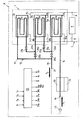
- the fuel cell 1 represented in FIG. 1 comprises first, second and third stack elements 3a, 3b and 3c inserted in branches 5a, 5b and 5c, respectively, of an electrical supply circuit 7.
- the battery cells 3a, 3b and 3c have optimal operating temperature ranges designated by P a , P b and P c , respectively.
- the electrical supply circuit 7, or “electrical circuit” 7, comprises in in addition to a branch 8, parallel to branches 5a, 5b and 5c, into which is inserted a battery 9.
- Switches 10a, 10b and 10c are inserted in the branches 5a, 5b and 5c, respectively. These switches constitute means of electrical connection selective of the battery cells 3a, 3b and 3c, respectively, in the supply circuit electric 7.
- a switch 11 is also inserted in the branch 8 in which is inserted the battery 9.
- the electrical supply circuit 7 is intended for the electrical supply of electrical consumers, not shown, of a vehicle V, for example at the power of an electric propulsion motor. Consumers are connected at the + and - terminals of the power supply circuit 7.
- the device according to the invention comprises a heating circuit 12 in which circulates a heat transfer fluid circulated by a pump 13.
- Circuit 12 has input and output branches, 14 and 15 respectively, connected together by a first common end 17, the heat transfer fluid entering through the second end 19 of said inlet branch 14 (arrow F1) and exiting through the second end 21 of said outlet branch 15 (arrow F2).
- Heat exchangers 23a, 23b and 23c, associated with the stack elements 3a, 3b and 3c, respectively, are inserted in series in the input branch 14.
- An exchanger is said to be “associated” with a stack element if a relation heat exchange can be established between this cell element and the heat transfer fluid crossing this interchange.
- Each of the exchangers 23a and 23b includes means for short-circuiting the or the exchangers inserted downstream.
- the heat transfer fluid leaving the exchanger 23a, respectively 23b, can thus return directly to the output branch 15, without passing through the exchangers 23b and 23c, respectively the exchanger 23c.
- the means of short-circuiting the exchanger (s) inserted downstream of the exchangers 23a and 23b have short-circuit branches 25a and 25b, shown in dashed lines, connected on the one hand to the input branch 14 immediately downstream of exchangers 23a and 23b, respectively, at points of connection 27a and 27b, respectively, and on the other hand to the output branch 15.
- Two valves 29a and 29b are inserted in the short-circuit branches 25a and 25b, respectively.
- Two valves 31a and 31b are also inserted in the inlet branch 14, immediately downstream of connection points 27a and 27b, respectively, short circuit branches 25a and 25b, respectively.
- An auxiliary heat exchanger 33 in heat exchange relationship with an auxiliary heat source 34, for example electrical resistances, is inserted in the inlet branch 14, upstream of the exchanger 23a.
- the device shown in FIG. 1 finally comprises a computer 35 at less aware of the electrical energy demand D of electrical consumers, temperatures Ta, Tb and Tc of the cell elements 3a, 3b and 3c, respectively, and controlling the position of the valves 29a, 29b, 31a and 31b, the position of the switches 10a, 10b, 10c and 11, as well as the starting or stopping of the heat source 34 and pump 13.
- the computer 35 controls the release of heat energy by the source 34, the opening of valve 29a, the closing of valves 29b and 31a, and the starting the pump 13.
- the heat transfer fluid receives heat energy which it transfers, at least in part, to the cell element 3a when it passes through the exchanger 23a.
- the heat transfer fluid joins the outlet branch 15 via the branch of bypass 25a.
- the exchangers 23b and 23c are therefore "inactivated", that is to say that heat transfer fluid does not flow through them.
- the reformer can serve as a heat source 34, insofar as its operating temperature, around 800 ° C, is higher than that of the fuel 1.
- the calorific energy released by the reformer otherwise lost.
- the reformer When vehicle V starts, the reformer must itself be heated, by example using a burner. In this situation, it is particularly advantageous to use as a heat source in heat exchange relationship with the exchanger 33 the hot gases generated by the burner and having served to heat the reformer, this heat energy otherwise being evacuated to the outside of vehicle V. This avoids the use of a specific heat source for the fuel cell 1.
- the heat energy supplied by the auxiliary heat source 34 is not intended only for the cell element 3a, which advantageously allows a rise rapid temperature of the latter.
- the response time to start the battery at fuel to a change in the demand for electrical energy is improved.
- the switch 10a When the temperature of the cell element 3a reaches the lower limit of the range P a , the switch 10a is closed so that the cell element 3a supplies electrical energy to the electrical consumers of the vehicle V.
- the supply of electrical energy by the cell element 3a is accompanied by a sufficient heat to keep the temperature substantially constant of the cell element 3a, or even to raise it.
- the computer 35 therefore controls the inactivation of the exchanger 33. Inactivation can result for example from bypassing the exchanger 33 by the heat transfer fluid for example by means of a branch branch, not represented.
- the computer 35 controls its stopping.
- the calculator 35 also controls the closing of valve 29a and valve 31b and the opening valves 31a and 29b so that the heat transfer fluid passes successively exchanger 23a by receiving heat energy, then exchanger 23b by yielding, at least in part, this calorific energy to the cell element 3b.
- the heat losses of the cell element 3a are therefore used to heat the battery cell 3b.
- the switch 10b When the temperature of the cell element 3b reaches the lower limit of the range P b , the switch 10b is closed so that the cell element 3b supplies electrical power to the electric consumers of the vehicle V.
- the rise in temperature of the cell element 3c then its connection to the electrical supply circuit 7 is then carried out like that of the cell element 3b.
- the valve 31b is open, the valve 29b closed, and the heat energy released by the cell elements 3a and 3b partly returned to the cell element 3c.
- the switch 10c closes and the battery cell 3c in turn supplies electrical power to the electrical consumers of the vehicle V.
- the thermal circuit 12 can be used to evacuate vehicle V to the outside, for example by via a radiator not shown, the heat energy released by these battery cells.
- the use, for heating the fuel cell 1, of a heat source 34 different from the fuel cell 1 itself is known, for example by the WO 01 03 216.
- the heat source 34 is only used for heating the single cell element 3a, which makes it possible to limit the energy supplied by the heat source 34 to heat the fuel cell 1.
- the computer 35 constantly checks the electrical energy demand of the consumers of the vehicle V. When the electrical energy delivered by the battery connected to the power supply circuit 7 is less than this demand and no additional battery cell can be connected to said circuit power supply, the computer 35 controls the closing of the switch 11. The battery 9 then supplies additional electrical energy.
- a cell element is not connected to the supply circuit electric only if its temperature is within its temperature range of optimal functioning.
- Battery 9 is recharged when consumer needs are lower than the production of electrical energy by the fuel cell 1.
- the cells constituting the battery cells 3a, 3b and 3c are designed to operate at a nominal voltage, typically of the order of 0.7 V. However, in operating these cells at a lower voltage, for example 0.6 V, the the electric power that these cells can supply increases.
- a single cell element whose cells operate at 0.6 V power does it generate about 40 to 50% of the power maximum generated by three identical battery cells connected in parallel and of which the cells operate at a nominal voltage of 0.7 V.
- the operation under voltage of cells causes a clearance significant heat energy, difficult to evacuate.
- it is only works only if consumers' demand for electrical energy exceeds the quantity maximum electrical energy that can be supplied by the connected battery cells at nominal voltage.
- the ramp-up time of a fuel cell using a process according to the invention is particularly rapid.
- the thermal circuit 12 does not include heat exchanger 33 and no auxiliary heat source 34 is in heat exchange relationship thermal with the heat transfer fluid.
- the increase in available power from the battery to fuel 1 is carried out as follows.
- the first cell element 3a is connected although its temperature is not optimal.
- the heat energy which it releases then is recovered to heat it until its temperature belongs to the optimal operating range P a .
- the heat energy released by the cell element 3a is used to heat the cell element 3b until the temperature of the latter belongs to the range P b , then the cell element 3b is connected to the circuit power supply 7.
- the heat energy released by the cell elements 3a and 3b is then used to heat the cell element 3c until the temperature of the latter belongs to the range P c , then the battery cell 3c is connected to the power supply circuit 7.
- the device according to this variant implements a circuit thermal 12 of simple architecture, not incorporating exchanger 33.
- the cell element 3a During its rise in temperature, the cell element 3a has performances poor energy. However, the other stack elements 3b and 3c are then heated by means of heat losses from battery cells operating with energy performance not degraded by too low a temperature. Overall, the energy performance of fuel cell 1 during its increase in power are therefore improved, without the need to resort to a auxiliary heat source 34.
- the heat losses of the cells of a cell element increase also when they are energized.
- the cells which compose it are operated at a voltage lower than their nominal voltage until the temperature of this element 3a belongs at the optimal operating range P a .
- one or more connected battery cells, and in particular the first cell element 3a can be kept under voltage after reaching an optimal operating temperature, so as to accelerate heating the remaining battery cells to be connected and / or increase the power electric available.
- the device and the method according to the invention can be generalized to a battery with fuel 1 with any number of cell elements, and to others fuel cells than PEM type fuel cells.
- the temperature thresholds from which the battery cells are electrically connected to the power supply circuit 7 may be different from those described.
- the ranges P a , P b and P c could for example designate ranges of operating temperatures estimated satisfactory, and not optimal, of the cell elements 3a, 3b and 3c, respectively.
- the stack elements could be connected in series, the electrical supply circuit comprising branches of bypass so as to divert the electrical current from one or more of these elements.
- a voltage converter would then be implemented so as to convert the voltage across the connected elements to a voltage suitable for the vehicle propulsion engine control.
- valves 29a and 31a can be replaced so equivalent by a single three-way valve inserted at junction 27a.
- the temperature adjustment and the connection disconnected battery cells could be carried out, no longer in proceeding from stack element by stack element, but proceeding by group of one or multiple battery cells disconnected.
Landscapes
- Engineering & Computer Science (AREA)
- Life Sciences & Earth Sciences (AREA)
- Sustainable Development (AREA)
- Sustainable Energy (AREA)
- Power Engineering (AREA)
- Transportation (AREA)
- Mechanical Engineering (AREA)
- Fuel Cell (AREA)
- Electric Propulsion And Braking For Vehicles (AREA)
Abstract
Description
- on utilise de l'énergie calorifique dégagée par au moins un desdits éléments de pile connectés pour chauffer, pendant l'étape a), ledit élément de pile déconnecté ;
- quand l'énergie électrique délivrée par lesdits éléments de pile connectés audit circuit d'alimentation électrique est inférieure à la demande d'énergie électrique dudit consommateur, on connecte des moyens de stockage d'énergie électrique audit circuit d'alimentation électrique ;
- quand l'énergie électrique délivrée par lesdits éléments de pile connectés audit circuit d'alimentation électrique est inférieure à la demande d'énergie électrique dudit consommateur, on met en sous tension des cellules d'au moins un desdits éléments de pile connectés ;
- on utilise l'énergie calorifique dégagée par une source calorifique auxiliaire pour ajuster ladite température pendant l'étape a);
- ladite source calorifique comporte des gaz chauds générés par un brûleur de chauffage d'un reformeur ;
- préalablement audit ajustement de la température et à ladite connexion électrique de chacun desdits éléments de pile de ladite pluralité, on connecte électriquement audit circuit d'alimentation électrique un premier élément de pile, puis on amène dans une plage de températures de fonctionnement optimal la température dudit premier élément de pile au moyen d'énergie calorifique dégagée par ledit premier élément de pile ;
- on fait fonctionner les cellules dudit premier élément de pile en sous tension au moins jusqu'à ce que la température dudit premier élément appartienne à sa plage de fonctionnement optimal ;
- on maintient en sous-tension au moins un desdits éléments de pile connectés. De préférence, ce maintien en sous-tension dure tant que tous les éléments de la pile n'ont pas atteint leur plage de température de fonctionnement optimal.
- lesdits éléments de pile sont insérés dans des branches parallèles dudit circuit d'alimentation électrique ;
- lesdits moyens de connexion électrique sélective comportent des interrupteurs insérés dans chacune desdites branches parallèles ;
- ledit circuit d'alimentation comporte au moins une batterie insérée dans une branche parallèle auxdites branches et des moyens de connexion sélective de ladite batterie audit circuit d'alimentation électrique, ce qui permet avantageusement de stocker de l'énergie pour en disposer quand les seuls éléments de pile connectés ne suffisent pas à la demande en énergie électrique des consommateurs;
- ladite source calorifique est une source calorifique auxiliaire ;
- ladite source calorifique est un desdits éléments de pile, ce qui permet avantageusement d'améliorer le rendement énergétique de l'opération de chauffage de la pile à combustible ;
- ladite source calorifique comporte des gaz chauds générés par un brûleur de chauffage d'un reformeur ;
- ledit circuit de chauffage comporte des branches d'entrée et de sortie ayant une première extrémité commune, le fluide caloporteur entrant par la deuxième extrémité de ladite branche d'entrée et sortant par la deuxième extrémité de ladite branche de sortie, une pluralité d'échangeurs thermiques associés chacun à au moins un dit élément de pile étant insérés en série dans ladite branche d'entrée, au moins un desdits échangeurs comportant des moyens de court-circuiter lesdits échangeurs insérés en son aval de manière que le fluide caloporteur sortant dudit échangeur retourne, au moins en partie, directement dans ladite branche de sortie ;
- lesdits moyens de court-circuiter lesdits échangeurs insérés en aval d'un échangeur comportent une branche de court-circuit connectée d'une part à ladite branche d'entrée immédiatement en aval dudit échangeur et d'autre part à ladite branche de sortie, deux vannes étant insérées respectivement dans ladite branche de court-circuit et dans ladite branche d'entrée, immédiatement en aval du point de connexion de ladite branche de court-circuit.
Claims (20)
- Procédé de gestion de la montée en puissance disponible d'une pile à combustiblecaractérisé en ce que , successivement pour chacun d'une pluralité des dits éléments de pile (3a,3b,3c) déconnectés électriquement dudit circuit (7), on procède selon les étapes suivantes :(1) insérée dans un circuit d'alimentation en énergie électrique (7) d'au moins un consommateur d'un véhicule automobile (V), notamment d'un moteur électrique de propulsion dudit véhicule (V), ladite pile à combustible (1) comportant au moins deux éléments de pile (3a,3b,3c) branchés en parallèle et aptes à être connectés sélectivement audit circuit d'alimentation électrique (7),a ) ajustement de la température dudit élément de pile (3a,3b,3c) déconnecté dans une plage de températures de fonctionnement optimal (Pa,Pb,Pc) dudit élément de pile(3a,3b,3c);b) connexion électrique audit circuit (7) dudit élément de pile (3a,3b,3c).
- Procédé selon la revendication 1, caractérisé en ce qu'on utilise de l'énergie calorifique dégagée par au moins un desdits éléments de pile (3a,3b) connectés pour chauffer, pendant l'étape a), ledit élément de pile déconnecté (3a,3b,3c).
- Procédé selon l'une quelconque des revendications 1 et 2, caractérisé en ce que, quand l'énergie électrique délivrée par lesdits éléments de pile connectés (3a,3b,3c) audit circuit d'alimentation électrique (7) est inférieure à la demande d'énergie électrique dudit consommateur, on connecte des moyens de stockage d'énergie électrique (9) audit circuit d'alimentation électrique (7).
- Procédé selon l'une quelconque des revendications précédentes, caractérisé en ce que, quand l'énergie électrique délivrée par lesdits éléments de pile (3a,3b,3c) connectés audit circuit d'alimentation électrique (7) est inférieure à la demande d'énergie électrique dudit consommateur, on met en sous tension des cellules d'au moins un desdits éléments de pile (3a,3b,3c) connectés.
- Procédé selon l'une quelconque des revendications précédentes, caractérisé en ce qu'on utilise l'énergie calorifique dégagée par une source calorifique auxiliaire (34) pour ajuster ladite température pendant l'étape a).
- Procédé selon la revendication 5, caractérisé en ce que ladite source calorifique (34) comporte des gaz chauds générés par un brûleur de chauffage d'un reformeur.
- Procédé selon l'une quelconque des revendications précédentes, caractérisé en ce que, préalablement audit ajustement de la température et à ladite connexion électrique de chacun desdits éléments de pile de ladite pluralité (3b,3c), on connecte électriquement audit circuit d'alimentation électrique (7) un premier élément de pile (3a), puis on amène dans une plage de températures de fonctionnement optimal (Pa) la température dudit premier élément de pile (3a) au moyen d'énergie calorifique dégagée par ledit premier élément de pile (3a).
- Procédé selon la revendication 7, caractérisé en ce qu'on fait fonctionner les cellules dudit premier élément de pile (3a) en sous tension au moins jusqu'à ce que la température dudit premier élément de pile (3a) appartienne à une plage de fonctionnement optimal (Pa).
- Procédé selon l'une quelconque des revendications précédentes, caractérisé en ce qu'on maintient en sous tension au moins un desdits éléments de pile connectés (3a,3b,3c).
- Dispositif de montée en puissance disponible d'une pile à combustible (1) insérée dans un circuit d'alimentation en énergie électrique (7) d'au moins un consommateur d'un véhicule automobile (V), notamment un moteur électrique de propulsion dudit véhicule (V), ladite pile à combustible (1) comportant une pluralité d'éléments de pile (3a,3b,3c) et ledit dispositif comportant un circuit thermique de chauffage et/ou de refroidissement(12) desdits éléments de pile (3a,3b,3c) et un calculateur de commande (35) dudit circuit d'alimentation électrique (7) et dudit circuit thermique (12),
caractérisé en ce que ledit circuit thermique(12) comporte des moyens de mise en relation d'échange thermique sélective (25a,25b,29a,29b,31a,31b) d'une source calorifique (34,3a,3b) avec au moins un desdits éléments de pile (3a,3b,3c), et ledit circuit d'alimentation électrique (7) comporte des moyens de connexion électrique sélective (10a,10b,10c) dudit élément de pile (3a,3b,3c) audit circuit d'alimentation électrique (7). - Dispositif selon la revendication 10, caractérisé en ce que lesdits éléments de pile (3a,3b,3c) sont insérés dans des branches parallèles (5a,5b,5c) dudit circuit d'alimentation électrique (7).
- Dispositif selon l'une des revendications 10 et 11, caractérisé en ce que lesdits moyens de connexion électrique sélective comportent des interrupteurs insérés (10a,10b,10c) dans chacune desdites branches parallèles (5a,5b,5c).
- Dispositif selon l'une quelconque des revendications 11 à 12, caractérisé en ce que ledit circuit d'alimentation électrique (7) comporte au moins une batterie (9) insérée dans une branche (8) parallèle auxdites branches (5a,5b,5c) et des moyens de connexion sélective (11) de ladite batterie (9) audit circuit d'alimentation électrique (7).
- Dispositif selon l'une quelconque des revendications 10 à 13, caractérisé en ce que ladite source calorifique est un desdits éléments de pile (3a,3b).
- Dispositif selon l'une quelconque des revendications 10 à 13, caractérisé en ce que ladite source calorifique est une source calorifique auxiliaire (34).
- Dispositif selon la revendication 15, caractérisé en ce que ladite source calorifique auxiliaire (34) comporte des gaz chauds générés par un brûleur de chauffage d'un reformeur.
- Dispositif selon l'une quelconque des revendications 10 à 16, caractérisé en ce que ledit circuit de chauffage (12) comporte des branches d'entrée (14) et de sortie (15) ayant une première extrémité commune (17), un fluide caloporteur entrant par la deuxième extrémité (19) de ladite branche d'entrée (14) et sortant par la deuxième extrémité (21) de ladite branche de sortie (15), une pluralité d'échangeurs thermiques (23a,23b,23c) associés chacun à au moins un desdits éléments de pile (3a,3b,3c) étant insérés en série dans ladite branche d'entrée (14), au moins un desdits échangeurs (23a;23b) comportant des moyens (25a;25b) de court-circuiter lesdits échangeurs insérés en son aval de manière que le fluide caloporteur sortant dudit échangeur (23a;23b) retourne, au moins en partie, directement dans ladite branche de sortie (15).
- Dispositif selon la revendication 17, caractérisé en ce que lesdits moyens (25a;25b) de court-circuiter lesdits échangeurs (23b,23c ; 23c) insérés en aval d'un échangeur (23a;23b) comportent une branche de court-circuit (25a;25b) connectée d'une part à ladite branche d'entrée (14) immédiatement en aval dudit échangeur (23a;23b) et d'autre part à ladite branche de sortie (15), deux vannes (29a,31a ; 29b,31b) étant insérées respectivement dans ladite branche de court-circuit (25a;25b) et dans ladite branche d'entrée (14), immédiatement en aval du point de connexion de ladite branche de court-circuit (25a;25b).
- Dispositif selon l'une quelconque des revendications 10 à 18, caractérisé en ce qu'il est mis en oeuvre selon un procédé conforme à l'une quelconque des revendications 1 à 18.
- Pile à combustible (1) insérée dans un circuit d'alimentation en énergie électrique (7) d'au moins un consommateur d'un véhicule automobile (V), notamment un moteur électrique de propulsion dudit véhicule (V), ladite pile à combustible (1) comportant une pluralité d'éléments de pile (3a,3b,3c) et étant équipée d'un dispositif destiné à améliorer son rendement énergétique pendant sa montée en puissance disponible, ledit dispositif comportant un circuit de chauffage (12) desdits éléments de pile (3a,3b,3c) et un calculateur de commande (35) desdits circuits d'alimentation électrique (7) et de chauffage (12),
caractérisé en ce que ledit dispositif est conforme à l'une quelconque des revendications 10 à 19.
Applications Claiming Priority (2)
| Application Number | Priority Date | Filing Date | Title |
|---|---|---|---|
| FR0116563A FR2834140B1 (fr) | 2001-12-20 | 2001-12-20 | Procede de gestion de la montee en puissance disponible d'une pile a combustible |
| FR0116563 | 2001-12-20 |
Publications (2)
| Publication Number | Publication Date |
|---|---|
| EP1323572A1 true EP1323572A1 (fr) | 2003-07-02 |
| EP1323572B1 EP1323572B1 (fr) | 2007-08-08 |
Family
ID=8870760
Family Applications (1)
| Application Number | Title | Priority Date | Filing Date |
|---|---|---|---|
| EP02293194A Expired - Lifetime EP1323572B1 (fr) | 2001-12-20 | 2002-12-20 | Procédé de gestion de la montée en puissance disponible d'une pile à combustible |
Country Status (4)
| Country | Link |
|---|---|
| EP (1) | EP1323572B1 (fr) |
| DE (1) | DE60221630T2 (fr) |
| ES (1) | ES2287234T3 (fr) |
| FR (1) | FR2834140B1 (fr) |
Cited By (1)
| Publication number | Priority date | Publication date | Assignee | Title |
|---|---|---|---|---|
| FR2884057A1 (fr) * | 2005-03-31 | 2006-10-06 | Renault Sas | Systeme de pile a combustible a plusieurs modules et procede de generation d'energie au moyen d'une pile a combustible |
Families Citing this family (1)
| Publication number | Priority date | Publication date | Assignee | Title |
|---|---|---|---|---|
| US11757117B2 (en) * | 2021-09-03 | 2023-09-12 | Hydrogenics Corporation | Fuel cell systems with series-connected subsystems |
Citations (6)
| Publication number | Priority date | Publication date | Assignee | Title |
|---|---|---|---|---|
| EP0664571A1 (fr) * | 1994-01-20 | 1995-07-26 | Fuji Electric Co., Ltd. | Générateur à piles à combustible et méthode pour son démarrage |
| DE19948215A1 (de) * | 1998-10-08 | 2000-04-13 | Vaillant Joh Gmbh & Co | Blockheizkraftwerk mit einem Stapel von Brennstoffzellen |
| EP0999078A1 (fr) * | 1998-11-04 | 2000-05-10 | Valeo Klimasysteme GmbH | Circuit de refroidissement/chauffage de véhicule |
| WO2000054355A1 (fr) * | 1999-03-09 | 2000-09-14 | Siemens Aktiengesellschaft | Batterie de piles a combustible dotee d'un systeme de chauffage et d'une meilleure performance de demarrage a froid et procede de demarrage a froid d'une batterie de piles a combustible |
| US6186254B1 (en) * | 1996-05-29 | 2001-02-13 | Xcelliss Fuel Cell Engines Inc. | Temperature regulating system for a fuel cell powered vehicle |
| WO2001095419A1 (fr) * | 2000-06-05 | 2001-12-13 | Siemens Aktiengesellschaft | Systeme de pile a combustible et procede pour la mise en marche et l'arret d'un systeme de pile a combustible |
-
2001
- 2001-12-20 FR FR0116563A patent/FR2834140B1/fr not_active Expired - Fee Related
-
2002
- 2002-12-20 ES ES02293194T patent/ES2287234T3/es not_active Expired - Lifetime
- 2002-12-20 DE DE60221630T patent/DE60221630T2/de not_active Expired - Lifetime
- 2002-12-20 EP EP02293194A patent/EP1323572B1/fr not_active Expired - Lifetime
Patent Citations (6)
| Publication number | Priority date | Publication date | Assignee | Title |
|---|---|---|---|---|
| EP0664571A1 (fr) * | 1994-01-20 | 1995-07-26 | Fuji Electric Co., Ltd. | Générateur à piles à combustible et méthode pour son démarrage |
| US6186254B1 (en) * | 1996-05-29 | 2001-02-13 | Xcelliss Fuel Cell Engines Inc. | Temperature regulating system for a fuel cell powered vehicle |
| DE19948215A1 (de) * | 1998-10-08 | 2000-04-13 | Vaillant Joh Gmbh & Co | Blockheizkraftwerk mit einem Stapel von Brennstoffzellen |
| EP0999078A1 (fr) * | 1998-11-04 | 2000-05-10 | Valeo Klimasysteme GmbH | Circuit de refroidissement/chauffage de véhicule |
| WO2000054355A1 (fr) * | 1999-03-09 | 2000-09-14 | Siemens Aktiengesellschaft | Batterie de piles a combustible dotee d'un systeme de chauffage et d'une meilleure performance de demarrage a froid et procede de demarrage a froid d'une batterie de piles a combustible |
| WO2001095419A1 (fr) * | 2000-06-05 | 2001-12-13 | Siemens Aktiengesellschaft | Systeme de pile a combustible et procede pour la mise en marche et l'arret d'un systeme de pile a combustible |
Non-Patent Citations (1)
| Title |
|---|
| BOSE B K ET AL: "Power and energy storage devices for next generation hybrid electric vehicle", ENERGY CONVERSION ENGINEERING CONFERENCE, 1996. IECEC 96., PROCEEDINGS OF THE 31ST INTERSOCIETY WASHINGTON, DC, USA 11-16 AUG. 1996, NEW YORK, NY, USA,IEEE, US, 11 August 1996 (1996-08-11), pages 1893 - 1898, XP010198025, ISBN: 0-7803-3547-3 * |
Cited By (1)
| Publication number | Priority date | Publication date | Assignee | Title |
|---|---|---|---|---|
| FR2884057A1 (fr) * | 2005-03-31 | 2006-10-06 | Renault Sas | Systeme de pile a combustible a plusieurs modules et procede de generation d'energie au moyen d'une pile a combustible |
Also Published As
| Publication number | Publication date |
|---|---|
| EP1323572B1 (fr) | 2007-08-08 |
| ES2287234T3 (es) | 2007-12-16 |
| FR2834140A1 (fr) | 2003-06-27 |
| DE60221630D1 (de) | 2007-09-20 |
| FR2834140B1 (fr) | 2005-06-03 |
| DE60221630T2 (de) | 2008-05-08 |
Similar Documents
| Publication | Publication Date | Title |
|---|---|---|
| EP3451485A1 (fr) | Dispositif de connexion électrique pour véhicule automobile refroidi par un circuit de fluide réfrigérant | |
| EP3676541B1 (fr) | Appareil de chauffage intégrant une batterie et un onduleur pour injecter de l'énergie de la batterie vers la source d'alimentation électrique | |
| EP3862201A1 (fr) | Dispositif de récuperation et de régulation d' énergie thermique d'un véhicule électrique à génerateur électrochimique avec un système hvac | |
| EP3899225A1 (fr) | Dispositif de gestion thermique d'un circuit de fluide caloporteur d'un véhicule hybride | |
| EP2613391A1 (fr) | Pile à combustible | |
| EP1323572B1 (fr) | Procédé de gestion de la montée en puissance disponible d'une pile à combustible | |
| EP4193410B1 (fr) | Pile à combustible, système de pile à combustible et procédé de contrôle du système | |
| FR3053851A1 (fr) | Dispositif de commande d'un systeme d'alimentation pour vehicule a couplage pile a combustible/batteries | |
| EP3503276B1 (fr) | Système de génération d'électricité incluant deux piles à combustible à temperatures de fonctionnement differentes | |
| EP3835555B1 (fr) | Dispositif de production d'énergie électrique comportant un accumulateur d'énergie thermique | |
| EP1733447B1 (fr) | Dispositif et procede de refroidissement d'un ensemble de generation d'electricite comprenant une pile a combustible. | |
| EP1733446B1 (fr) | Dispositif et procede de refroidissement d'un module de puissance d'une pile a combustible | |
| EP2158633A2 (fr) | Procede de regulation de la temperature d'une ligne d'admission cathodique d'une pile a combustible | |
| WO2025099222A1 (fr) | Système de pile à combustible amélioré | |
| FR2813994A1 (fr) | Pile a combustible et procede de protection d'une telle pile contre le gel | |
| WO2025032212A1 (fr) | Methode et systeme de production d'electricite en situation stationnaire autonome | |
| FR2893186A3 (fr) | Dispositif de pile a combustible avec systeme de refroidissement et systeme de purification d'eau | |
| EP4635016A1 (fr) | Pile à combustible | |
| FR2917903A1 (fr) | Dispositif de regulation de la regeneration du liquide d'echange de chaleur d'une pile a combustible | |
| FR2884057A1 (fr) | Systeme de pile a combustible a plusieurs modules et procede de generation d'energie au moyen d'une pile a combustible | |
| EP1730806B1 (fr) | Procede de regulation de la pression d'un gaz d'echappement d'une pile a combustible de maniere a reguler l'aptitude a la condensation de ce gaz | |
| WO2016189162A2 (fr) | Installation de cogeneration comprenant une pile a combustible sofc fonctionnant au gaz naturel, au demarrage facilite eta la securite accrue | |
| FR3149431A1 (fr) | Systeme de gestion thermique d’un vehicule electrique a pile a combustible | |
| FR3151710A1 (fr) | Vehicule automobile comportant des moyens de gestion thermique d’une pile a combustible | |
| WO2006040490A1 (fr) | Generateur d'electricite pour vehicule automobile |
Legal Events
| Date | Code | Title | Description |
|---|---|---|---|
| PUAI | Public reference made under article 153(3) epc to a published international application that has entered the european phase |
Free format text: ORIGINAL CODE: 0009012 |
|
| AK | Designated contracting states |
Designated state(s): AT BE BG CH CY CZ DE DK EE ES FI FR GB GR IE IT LI LU MC NL PT SE SI SK TR |
|
| AX | Request for extension of the european patent |
Extension state: AL LT LV MK RO |
|
| 17P | Request for examination filed |
Effective date: 20031215 |
|
| AKX | Designation fees paid |
Designated state(s): BE DE ES FR GB IT |
|
| GRAP | Despatch of communication of intention to grant a patent |
Free format text: ORIGINAL CODE: EPIDOSNIGR1 |
|
| GRAS | Grant fee paid |
Free format text: ORIGINAL CODE: EPIDOSNIGR3 |
|
| GRAA | (expected) grant |
Free format text: ORIGINAL CODE: 0009210 |
|
| AK | Designated contracting states |
Kind code of ref document: B1 Designated state(s): BE DE ES FR GB IT |
|
| REG | Reference to a national code |
Ref country code: GB Ref legal event code: FG4D Free format text: NOT ENGLISH |
|
| REF | Corresponds to: |
Ref document number: 60221630 Country of ref document: DE Date of ref document: 20070920 Kind code of ref document: P |
|
| GBT | Gb: translation of ep patent filed (gb section 77(6)(a)/1977) |
Effective date: 20070912 |
|
| REG | Reference to a national code |
Ref country code: ES Ref legal event code: FG2A Ref document number: 2287234 Country of ref document: ES Kind code of ref document: T3 |
|
| PLBE | No opposition filed within time limit |
Free format text: ORIGINAL CODE: 0009261 |
|
| STAA | Information on the status of an ep patent application or granted ep patent |
Free format text: STATUS: NO OPPOSITION FILED WITHIN TIME LIMIT |
|
| BERE | Be: lapsed |
Owner name: RENAULT S.A.S. Effective date: 20071231 |
|
| 26N | No opposition filed |
Effective date: 20080509 |
|
| PG25 | Lapsed in a contracting state [announced via postgrant information from national office to epo] |
Ref country code: BE Free format text: LAPSE BECAUSE OF NON-PAYMENT OF DUE FEES Effective date: 20071231 |
|
| REG | Reference to a national code |
Ref country code: FR Ref legal event code: ST Effective date: 20081020 |
|
| PG25 | Lapsed in a contracting state [announced via postgrant information from national office to epo] |
Ref country code: FR Free format text: LAPSE BECAUSE OF NON-PAYMENT OF DUE FEES Effective date: 20071231 |
|
| PGFP | Annual fee paid to national office [announced via postgrant information from national office to epo] |
Ref country code: GB Payment date: 20101221 Year of fee payment: 9 |
|
| PGFP | Annual fee paid to national office [announced via postgrant information from national office to epo] |
Ref country code: ES Payment date: 20111227 Year of fee payment: 10 |
|
| PGFP | Annual fee paid to national office [announced via postgrant information from national office to epo] |
Ref country code: DE Payment date: 20111222 Year of fee payment: 10 |
|
| PGFP | Annual fee paid to national office [announced via postgrant information from national office to epo] |
Ref country code: IT Payment date: 20111228 Year of fee payment: 10 |
|
| GBPC | Gb: european patent ceased through non-payment of renewal fee |
Effective date: 20121220 |
|
| REG | Reference to a national code |
Ref country code: DE Ref legal event code: R119 Ref document number: 60221630 Country of ref document: DE Effective date: 20130702 |
|
| PG25 | Lapsed in a contracting state [announced via postgrant information from national office to epo] |
Ref country code: DE Free format text: LAPSE BECAUSE OF NON-PAYMENT OF DUE FEES Effective date: 20130702 |
|
| PG25 | Lapsed in a contracting state [announced via postgrant information from national office to epo] |
Ref country code: GB Free format text: LAPSE BECAUSE OF NON-PAYMENT OF DUE FEES Effective date: 20121220 |
|
| PG25 | Lapsed in a contracting state [announced via postgrant information from national office to epo] |
Ref country code: IT Free format text: LAPSE BECAUSE OF NON-PAYMENT OF DUE FEES Effective date: 20121220 |
|
| REG | Reference to a national code |
Ref country code: ES Ref legal event code: FD2A Effective date: 20140307 |
|
| PG25 | Lapsed in a contracting state [announced via postgrant information from national office to epo] |
Ref country code: ES Free format text: LAPSE BECAUSE OF NON-PAYMENT OF DUE FEES Effective date: 20121221 |