EP1323568A2 - Fuel vapor vent valve with peel-off mechanism for ensuring reopening - Google Patents
Fuel vapor vent valve with peel-off mechanism for ensuring reopening Download PDFInfo
- Publication number
- EP1323568A2 EP1323568A2 EP02027096A EP02027096A EP1323568A2 EP 1323568 A2 EP1323568 A2 EP 1323568A2 EP 02027096 A EP02027096 A EP 02027096A EP 02027096 A EP02027096 A EP 02027096A EP 1323568 A2 EP1323568 A2 EP 1323568A2
- Authority
- EP
- European Patent Office
- Prior art keywords
- float
- cage
- seal
- valve seat
- valve
- Prior art date
- Legal status (The legal status is an assumption and is not a legal conclusion. Google has not performed a legal analysis and makes no representation as to the accuracy of the status listed.)
- Granted
Links
Images

Classifications
-
- F—MECHANICAL ENGINEERING; LIGHTING; HEATING; WEAPONS; BLASTING
- F16—ENGINEERING ELEMENTS AND UNITS; GENERAL MEASURES FOR PRODUCING AND MAINTAINING EFFECTIVE FUNCTIONING OF MACHINES OR INSTALLATIONS; THERMAL INSULATION IN GENERAL
- F16K—VALVES; TAPS; COCKS; ACTUATING-FLOATS; DEVICES FOR VENTING OR AERATING
- F16K24/00—Devices, e.g. valves, for venting or aerating enclosures
- F16K24/04—Devices, e.g. valves, for venting or aerating enclosures for venting only
- F16K24/042—Devices, e.g. valves, for venting or aerating enclosures for venting only actuated by a float
- F16K24/044—Devices, e.g. valves, for venting or aerating enclosures for venting only actuated by a float the float being rigidly connected to the valve element, the assembly of float and valve element following a substantially translational movement when actuated, e.g. also for actuating a pilot valve
-
- B—PERFORMING OPERATIONS; TRANSPORTING
- B60—VEHICLES IN GENERAL
- B60K—ARRANGEMENT OR MOUNTING OF PROPULSION UNITS OR OF TRANSMISSIONS IN VEHICLES; ARRANGEMENT OR MOUNTING OF PLURAL DIVERSE PRIME-MOVERS IN VEHICLES; AUXILIARY DRIVES FOR VEHICLES; INSTRUMENTATION OR DASHBOARDS FOR VEHICLES; ARRANGEMENTS IN CONNECTION WITH COOLING, AIR INTAKE, GAS EXHAUST OR FUEL SUPPLY OF PROPULSION UNITS IN VEHICLES
- B60K15/00—Arrangement in connection with fuel supply of combustion engines or other fuel consuming energy converters, e.g. fuel cells; Mounting or construction of fuel tanks
- B60K15/03—Fuel tanks
- B60K15/035—Fuel tanks characterised by venting means
-
- B—PERFORMING OPERATIONS; TRANSPORTING
- B60—VEHICLES IN GENERAL
- B60K—ARRANGEMENT OR MOUNTING OF PROPULSION UNITS OR OF TRANSMISSIONS IN VEHICLES; ARRANGEMENT OR MOUNTING OF PLURAL DIVERSE PRIME-MOVERS IN VEHICLES; AUXILIARY DRIVES FOR VEHICLES; INSTRUMENTATION OR DASHBOARDS FOR VEHICLES; ARRANGEMENTS IN CONNECTION WITH COOLING, AIR INTAKE, GAS EXHAUST OR FUEL SUPPLY OF PROPULSION UNITS IN VEHICLES
- B60K15/00—Arrangement in connection with fuel supply of combustion engines or other fuel consuming energy converters, e.g. fuel cells; Mounting or construction of fuel tanks
- B60K15/03—Fuel tanks
- B60K15/035—Fuel tanks characterised by venting means
- B60K15/03519—Valve arrangements in the vent line
-
- Y—GENERAL TAGGING OF NEW TECHNOLOGICAL DEVELOPMENTS; GENERAL TAGGING OF CROSS-SECTIONAL TECHNOLOGIES SPANNING OVER SEVERAL SECTIONS OF THE IPC; TECHNICAL SUBJECTS COVERED BY FORMER USPC CROSS-REFERENCE ART COLLECTIONS [XRACs] AND DIGESTS
- Y10—TECHNICAL SUBJECTS COVERED BY FORMER USPC
- Y10T—TECHNICAL SUBJECTS COVERED BY FORMER US CLASSIFICATION
- Y10T137/00—Fluid handling
- Y10T137/0318—Processes
- Y10T137/0324—With control of flow by a condition or characteristic of a fluid
-
- Y—GENERAL TAGGING OF NEW TECHNOLOGICAL DEVELOPMENTS; GENERAL TAGGING OF CROSS-SECTIONAL TECHNOLOGIES SPANNING OVER SEVERAL SECTIONS OF THE IPC; TECHNICAL SUBJECTS COVERED BY FORMER USPC CROSS-REFERENCE ART COLLECTIONS [XRACs] AND DIGESTS
- Y10—TECHNICAL SUBJECTS COVERED BY FORMER USPC
- Y10T—TECHNICAL SUBJECTS COVERED BY FORMER US CLASSIFICATION
- Y10T137/00—Fluid handling
- Y10T137/0753—Control by change of position or inertia of system
- Y10T137/0874—Vent opening or closing on tipping container
-
- Y—GENERAL TAGGING OF NEW TECHNOLOGICAL DEVELOPMENTS; GENERAL TAGGING OF CROSS-SECTIONAL TECHNOLOGIES SPANNING OVER SEVERAL SECTIONS OF THE IPC; TECHNICAL SUBJECTS COVERED BY FORMER USPC CROSS-REFERENCE ART COLLECTIONS [XRACs] AND DIGESTS
- Y10—TECHNICAL SUBJECTS COVERED BY FORMER USPC
- Y10T—TECHNICAL SUBJECTS COVERED BY FORMER US CLASSIFICATION
- Y10T137/00—Fluid handling
- Y10T137/2931—Diverse fluid containing pressure systems
- Y10T137/3003—Fluid separating traps or vents
- Y10T137/3084—Discriminating outlet for gas
- Y10T137/309—Fluid sensing valve
- Y10T137/3099—Float responsive
Definitions
- the present invention relates to vapor vent valves of the type employed in fuel tanks filled with volatile fuel for operating an internal combustion engine and for which it is desired to control the emission of fuel vapors during periods in which the engine is not operating.
- a known float operated valve has employed a relatively thin flexible membrane valve member to effectuate closing with a relatively low closing force acting thereon.
- problems have been experienced with such valves upon the tank being completely filled with liquid fuel with the valve sticking closed or "corking". Subsequently, when fuel is withdrawn and the float descends to a level intended to reopen the valve, the increased vapor pressure acts to continue to hold the membrane valve member closed on the valve seat.
- the present invention solves the above described problem by providing a float actuated fuel vapor vent valve having a flexible elastomeric membrane type valve member caged for limited lost motion movement on the float assembly, with the upper portion of the cage having a downwardly extending projection for effecting localized peeling of the valve member from the valve seat upon lowering of the float assembly due to withdrawal of the liquid fuel from the tank.
- a preferred form of the float assembly has the cage formed with an inclined upper portion to effect peeling away of one side of the membrane from the valve seat thereby minimizing the force required to continue reopening of the valve on further lowering of the float assembly to ensure complete re-opening.
- FIG. 1 is a cross-section of the valve assembly employed in the present invention.
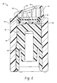
- FIG. 2 is an enlarged view of the float assembly employed in the valve of FIG. 1.
- the valve assembly of the present invention is indicated generally at 10 and includes a body or housing indicated generally at 12 which includes an upper portion 14 intended to be disposed externally of the fuel tank and which includes a hose fitting 16 having formed therein a vapor outlet passage 18.
- the upper portion 14 of the housing includes an outwardly extending annular flange portion 20.
- the valve body 12 further includes a downwardly extending portion 22 which is intended to extend into the interior of the fuel tank through the access opening (not shown) provided the tank; and, the portion 22 has formed therein a float cavity 24 which has slidably received therein a float assembly indicated generally at 26.
- the outward extending flange 20 formed on the upper portion 14 has an annular attachment flange 28 disposed thereover preferably by plastic overmolding and which includes a support or retainer ring 30 which engages flange 28 and the portion 22.
- An elastomeric seal material 32 is formed over the outer periphery thereof and which forms a substantially vapor impervious seal between the flange 20 and the overmold 28. It will be understood that overmold 28 is adapted for weldment to a plastic tank of similar material.
- a valve seat member 34 is disposed in body 12 and includes an annular valve seat 36 formed on the lower end of a valving passage 38 extending vertically through member 34.
- the upper end of the passage 38 has seated thereon a preferably spherical gravity responsive check valve 40 which is positioned thereon by an annular retaining wall 42 preferably formed as part of the valve seat member 34.
- guard or cover 44 which, in the presence practice of the invention, preferably has a cup shaped configuration, or alternatively a U-shaped configuration, and which may be secured over the lower portion of the body 22 with any suitable expedient such as by snap locking engagement or by weldment.
- the upper end of the vapor passage 38 has at least one, and preferably a plurality, of cross grooves 46 formed thereon to permit a minimum bleed flow of fuel vapor when the check valve 40 is registered against the end of the passage 38.
- the downward force of the weight of the check valve 40 is overcome by the pressure acting over the area of the seated valve; and, this pressure causes the valve 40 to move upwardly increasing the flow area to relieve the pressure.
- the float assembly 26 is shown in greater detail and includes a body having a generally annular or tubular configuration denoted by reference numeral 48 with a core 50 disposed therein and which preferably has a curved surface 52 formed on the upper end thereof.
- the core 50 may be secured within the body 48 by any suitable expedient as for example by snap locking or by weldment.
- the body 48 has a cage 54 formed on the upper end thereof in which is received a resilient flexible valve member denoted by reference numeral 56 preferably having a relatively thin membrane configuration and preferably with an annular bead rim 58 disposed about the outer periphery thereof and preferably formed integrally therewith.
- a rigid plate or disk 60 is disposed under the valve member 58 and is seated on the curved surface 52 for pivotal movement thereon and extends outwardly to contact the bead 58 to provide a registration or seating surface therefor.
- the cage 54 has the upper end 62 thereof inclined at an angle to the axis of the float body 48; and, the upper end 62 of the cage includes a downwardly extending projection 64 which is preferably located adjacent the inner periphery of the bead 58.
- the projection 64 is operative to provide localized contact and deflection of the membrane 56 upon downward movement of the float assembly 26 as will be herein after described in greater detail. It will be understood that the cage 54 is of sufficient height from the core 52 to permit limited relative motion or lost motion therein of the valve member 56 and the disc 60.
- the float assembly is biased upward by a spring 66 having its lower end registered against the inside of the cup 44 with the upper end of the spring 66 registered in an annular grooves 68 formed in the lower end of the core 50.
- the float In operation, as the fuel level in the tank rises, the float is moved upwardly to the position shown in dashed outline in FIG. 1 whereupon the valve member or membrane 56 contacts the valve seat 36, and is sealed thereagainst by the disc 60 pressing against the peripheral bead 58 of the membrane as the curved surface 52 of the float core contacts the under surface of the disc 50.
- the float assembly 26 Upon withdrawal of fuel from the tank and the lowering of the fuel level, the float assembly 26 is lowered causing the projection 64 to contact locally a portion of the valve member or membrane 56 to effect localized peeling of that portion of the valve member 56 from the valve seat 36 thereby preventing the valve member or membrane 56 from sticking against the valve seat 36. Further downward movement of the float assembly 26 causes the underside of the top 62 of the cage to contact the bead rim 58 of the valve member and effect a further peel away of one side thereof. Upon further lowering of the float assembly 26 the upper or higher portion of cage 62 contacts the side of membrane valve member rim 58 opposite projection 64 and effects complete opening of the valve member from the seat 36.
- the present invention thus provides, a unique and novel construction for a float operated fuel vapor vent valve having a relatively thin resilient valve member mounted within a cage on the float for limited lost motion on the float for sealing on a stationary vapor vent valve seat as the float rises.
- a downwardly extending projection on the float cage contacts a localized area of the valve membrane and causes the localized area to be peeled away from the valve seat thereby preventing the valve from remaining in a completely closed condition.
- the cage peels this member 56 completely away from the valve seat.
Landscapes
- Engineering & Computer Science (AREA)
- General Engineering & Computer Science (AREA)
- Mechanical Engineering (AREA)
- Transportation (AREA)
- Chemical & Material Sciences (AREA)
- Combustion & Propulsion (AREA)
- Life Sciences & Earth Sciences (AREA)
- Sustainable Energy (AREA)
- Sustainable Development (AREA)
- Cooling, Air Intake And Gas Exhaust, And Fuel Tank Arrangements In Propulsion Units (AREA)
- Self-Closing Valves And Venting Or Aerating Valves (AREA)
- Supplying Secondary Fuel Or The Like To Fuel, Air Or Fuel-Air Mixtures (AREA)
- Float Valves (AREA)
- Separation Using Semi-Permeable Membranes (AREA)
Abstract
Description
Claims (12)
- A vapor vent valve assembly for a fuel tank comprising:(a) a housing defining a vent passage (38) and a valve seat (36) at one end of said passage;(b) a float assembly (26) associated with the housing and guided for movement with respect thereto, and including a resilient seal member (56) captured for limited lost motion with respect thereto, said seal positioned for contacting said valve seat upon said float assembly rising in response to the fuel level rising to a certain level; and,(c) said float assembly further including a downwardly extending projection (64) operable for contacting and effecting localized deflection of said seal away from contact with said valve seat upon the fuel level decreasing below said certain level and said float assembly descending.
- The vent valve assembly defined in claim 1, wherein said resilient seal (56) has a relatively thin circular configuration.
- The vent valve assembly defined in claim 1, wherein said resilient seal (56) has a relatively thin configuration with an enlarged peripheral bead (58) formed therearound.
- The vent valve assembly defined in claim 1, wherein said resilient seal (56) has a relatively thin configuration with an annular bead (58) formed integrally about the periphery thereof.
- The vent valve assembly defined in claim 1, wherein said float assembly includes a cage (54) surrounding said resilient seal and operative to permit said limited lost motion between said seal and said cage with said projection (64) extending downwardly from said cage.
- The vent valve assembly defined in claim 6, wherein said cage has an upper portion (62) thereof inclined to the direction of the fluid level.
- The vent valve assembly defined in claim 1, wherein said float assembly includes a cage (54) for said capture of said seal (56); and, said cage has said downwardly extending projection (64) formed integrally therewith.
- A method of controlling vapor venting in a fuel tank comprising:(a) providing a vent port (38) through the wall of the tank and providing an annular valve seat (36) about the vent port;(b) capturing a resilient seal (56) for limited lost motion on a float (50) and disposing said float for moving said seal to contact said valve seat upon upward float movement;(c) disposing a downwardly extending projection (64) on the float and contacting the seal locally with the projection and effecting a localized peel-away movement of the seal from the valve seat upon downward float movement.
- The method defined in claim 8, wherein said step of capturing a resilient seal includes forming a cage (54) on the float and disposing the resilient seal in the cage.
- The method defined in claim 9, wherein said step of forming a cage includes the forming of the downwardly extending projection.
- The method defined in claim 8, wherein said step of capturing a resilient seal includes forming a cage on the float and disposing a relatively thin disc (56) within the cage.
- The method defined in claim 11, wherein said step of disposing a disc includes forming an annular bead (58) about the periphery of the disc.
Applications Claiming Priority (2)
| Application Number | Priority Date | Filing Date | Title |
|---|---|---|---|
| US14481 | 1993-02-08 | ||
| US10/014,481 US6691725B2 (en) | 2001-12-14 | 2001-12-14 | Fuel vapor vent valve with peel-off mechanism for ensuring reopening |
Publications (3)
| Publication Number | Publication Date |
|---|---|
| EP1323568A2 true EP1323568A2 (en) | 2003-07-02 |
| EP1323568A3 EP1323568A3 (en) | 2005-09-21 |
| EP1323568B1 EP1323568B1 (en) | 2007-10-10 |
Family
ID=21765758
Family Applications (1)
| Application Number | Title | Priority Date | Filing Date |
|---|---|---|---|
| EP02027096A Expired - Lifetime EP1323568B1 (en) | 2001-12-14 | 2002-12-04 | Fuel vapor vent valve with peel-off mechanism for ensuring reopening |
Country Status (11)
| Country | Link |
|---|---|
| US (1) | US6691725B2 (en) |
| EP (1) | EP1323568B1 (en) |
| JP (1) | JP4314398B2 (en) |
| KR (1) | KR100907167B1 (en) |
| AR (1) | AR038009A1 (en) |
| AU (1) | AU2002306206B2 (en) |
| BR (1) | BR0205567A (en) |
| CA (1) | CA2414041A1 (en) |
| DE (1) | DE60222853T2 (en) |
| MX (1) | MXPA02012387A (en) |
| TW (1) | TW567279B (en) |
Cited By (4)
| Publication number | Priority date | Publication date | Assignee | Title |
|---|---|---|---|---|
| WO2005012773A1 (en) | 2003-07-31 | 2005-02-10 | Siemens Aktiengesellschaft | Subunit for an additional control valve device used for an intake pipe of a reciprocating internal combustion engine |
| US7318576B2 (en) | 2004-05-27 | 2008-01-15 | Alfmeier Prazision Ag Baugruppen Und Systemlosungen | Bi-directional air valve for a tank system of a motor vehicle |
| US7543597B2 (en) | 2005-10-07 | 2009-06-09 | Alfmeier Corporation | Vent valve assembly with lever arrangement |
| CN104936810A (en) * | 2013-01-24 | 2015-09-23 | 考特克斯·特克斯罗恩有限公司及两合公司 | Venting apparatus for liquid containers, in particular for liquid containers for aqueous urea solution |
Families Citing this family (22)
| Publication number | Priority date | Publication date | Assignee | Title |
|---|---|---|---|---|
| US6915812B2 (en) | 2000-09-12 | 2005-07-12 | Alfmeier Corporation | Low permeation weldable fuel tank assembly |
| US6966330B2 (en) | 2003-08-27 | 2005-11-22 | Alfmeier Corporation | Weldring with locking arrangement for valve assembly |
| US7146729B2 (en) * | 2003-09-15 | 2006-12-12 | Eaton Corporation | Fuel vapor vent valve and method of attaching same to a tank |
| US6918405B2 (en) | 2003-12-04 | 2005-07-19 | Alfmeier Corporation | Fill limit vent valve |
| US7163023B2 (en) * | 2004-07-15 | 2007-01-16 | Eaton Corporation | Fuel vapor vent valve float assembly and method of making same |
| US7249595B2 (en) * | 2005-03-16 | 2007-07-31 | Eaton Corporation | Vapor vent valve with pressure relief function integrated to carbon canister |
| WO2006113756A2 (en) * | 2005-04-20 | 2006-10-26 | Be Intellectual Property, Inc. | Air vent valve for beverage makers |
| JP2007126971A (en) * | 2005-11-01 | 2007-05-24 | Kyosan Denki Co Ltd | Valve opening structure of float valve |
| JP4603949B2 (en) * | 2005-07-29 | 2010-12-22 | 豊田合成株式会社 | Fuel shut-off valve |
| DE102005036932B8 (en) * | 2005-08-05 | 2008-07-03 | Alfmeier Präzision AG Baugruppen und Systemlösungen | Bleed valve for the fuel tank of motor vehicles |
| JP5091689B2 (en) * | 2008-01-10 | 2012-12-05 | 株式会社パイオラックス | Float valve device |
| US8230873B2 (en) * | 2008-09-08 | 2012-07-31 | Eaton Corporaton | Fuel tank valve assembly with adjustable bypass vent flow |
| JP5801086B2 (en) * | 2011-04-04 | 2015-10-28 | 株式会社ニフコ | Fuel tank connector |
| EP2607135B1 (en) * | 2011-12-22 | 2014-07-02 | Volvo Car Corporation | Fuel ventilation system valve |
| EP2847018B1 (en) * | 2012-05-10 | 2016-04-27 | Eaton Corporation | Quick response float-operated vapor vent valve |
| WO2014011229A1 (en) | 2012-07-12 | 2014-01-16 | Eaton Corporation | Flapper valve with guide legs |
| WO2014105453A2 (en) * | 2012-12-24 | 2014-07-03 | Eaton Corporation | Valve assembly for a tank of a vehicle |
| USD768264S1 (en) * | 2013-11-26 | 2016-10-04 | Jong-Ha Park | Apparatus for preventing fluid gas explosion and cleaning and sterilizing fluid supplying line |
| JP6157404B2 (en) * | 2014-05-09 | 2017-07-05 | 株式会社ニフコ | Valve device |
| CN105042149A (en) * | 2015-08-27 | 2015-11-11 | 孙达立 | Oil filling limiting stop valve |
| DE102016211160A1 (en) * | 2016-06-22 | 2017-12-28 | Röchling Automotive SE & Co. KG | Filling head for a service liquid tank with gas and liquid valve body |
| KR102463193B1 (en) * | 2017-12-19 | 2022-11-03 | 현대자동차 주식회사 | Purge control solenoid valve |
Family Cites Families (8)
| Publication number | Priority date | Publication date | Assignee | Title |
|---|---|---|---|---|
| US4753262A (en) * | 1987-02-06 | 1988-06-28 | G.T. Products, Inc. | Fuel system vent valve having roll-over closure with improved re-opening action for venting |
| JP2549551B2 (en) * | 1988-10-20 | 1996-10-30 | 豊田合成株式会社 | Fuel cut-off valve |
| US5313977A (en) * | 1992-11-12 | 1994-05-24 | G. T. Products, Inc. | Fluid-responsive vent control valve with peel-away opening action |
| US5782258A (en) * | 1995-12-11 | 1998-07-21 | Alfmeier Corporation | Vapor recovery fuel tank system |
| US5960817A (en) * | 1997-11-03 | 1999-10-05 | Walbro Corporation | Control valve and system for fuel vapor recovery |
| US6035883A (en) * | 1998-03-13 | 2000-03-14 | Eaton Corporation | Weldable vapor vent valve for fuel tanks |
| US6371146B1 (en) * | 2000-11-07 | 2002-04-16 | Eaton Corporation | Peelaway type rollover valve element |
| US6508263B1 (en) * | 2001-09-20 | 2003-01-21 | Eaton Corporation | Float operated fuel tank vapor vent valve |
-
2001
- 2001-12-14 US US10/014,481 patent/US6691725B2/en not_active Expired - Lifetime
-
2002
- 2002-11-27 AU AU2002306206A patent/AU2002306206B2/en not_active Expired - Fee Related
- 2002-11-28 TW TW091134596A patent/TW567279B/en active
- 2002-12-04 EP EP02027096A patent/EP1323568B1/en not_active Expired - Lifetime
- 2002-12-04 DE DE60222853T patent/DE60222853T2/en not_active Expired - Lifetime
- 2002-12-10 JP JP2002358084A patent/JP4314398B2/en not_active Expired - Fee Related
- 2002-12-11 BR BR0205567-8A patent/BR0205567A/en not_active IP Right Cessation
- 2002-12-12 AR ARP020104817A patent/AR038009A1/en active IP Right Grant
- 2002-12-12 CA CA002414041A patent/CA2414041A1/en not_active Abandoned
- 2002-12-13 MX MXPA02012387A patent/MXPA02012387A/en unknown
- 2002-12-13 KR KR1020020079479A patent/KR100907167B1/en not_active Expired - Fee Related
Cited By (4)
| Publication number | Priority date | Publication date | Assignee | Title |
|---|---|---|---|---|
| WO2005012773A1 (en) | 2003-07-31 | 2005-02-10 | Siemens Aktiengesellschaft | Subunit for an additional control valve device used for an intake pipe of a reciprocating internal combustion engine |
| US7318576B2 (en) | 2004-05-27 | 2008-01-15 | Alfmeier Prazision Ag Baugruppen Und Systemlosungen | Bi-directional air valve for a tank system of a motor vehicle |
| US7543597B2 (en) | 2005-10-07 | 2009-06-09 | Alfmeier Corporation | Vent valve assembly with lever arrangement |
| CN104936810A (en) * | 2013-01-24 | 2015-09-23 | 考特克斯·特克斯罗恩有限公司及两合公司 | Venting apparatus for liquid containers, in particular for liquid containers for aqueous urea solution |
Also Published As
| Publication number | Publication date |
|---|---|
| JP2003193925A (en) | 2003-07-09 |
| EP1323568A3 (en) | 2005-09-21 |
| US20030111111A1 (en) | 2003-06-19 |
| TW567279B (en) | 2003-12-21 |
| DE60222853T2 (en) | 2008-07-10 |
| KR20030051294A (en) | 2003-06-25 |
| US6691725B2 (en) | 2004-02-17 |
| KR100907167B1 (en) | 2009-07-09 |
| CA2414041A1 (en) | 2003-06-14 |
| DE60222853D1 (en) | 2007-11-22 |
| AU2002306206B2 (en) | 2007-05-24 |
| AR038009A1 (en) | 2004-12-22 |
| MXPA02012387A (en) | 2003-06-24 |
| BR0205567A (en) | 2004-08-03 |
| EP1323568B1 (en) | 2007-10-10 |
| JP4314398B2 (en) | 2009-08-12 |
| TW200300816A (en) | 2003-06-16 |
Similar Documents
| Publication | Publication Date | Title |
|---|---|---|
| US6691725B2 (en) | Fuel vapor vent valve with peel-off mechanism for ensuring reopening | |
| US6508263B1 (en) | Float operated fuel tank vapor vent valve | |
| EP2847018B1 (en) | Quick response float-operated vapor vent valve | |
| US4991615A (en) | Tank pressure control apparatus | |
| US6742536B2 (en) | Attachment of fuel vapor vent valve to the inside of a fuel tank | |
| US4953583A (en) | Tank pressure control valve | |
| US6371146B1 (en) | Peelaway type rollover valve element | |
| EP0997674B1 (en) | Two-stage fuel tank vapor recovery vent valve and method of making same | |
| US6708713B1 (en) | Fill limit control valve assembly having a liquid fuel trap | |
| US4753262A (en) | Fuel system vent valve having roll-over closure with improved re-opening action for venting | |
| US8485215B2 (en) | Liquid tank venting system | |
| JPH08225022A (en) | Liquid cutoff valve | |
| EP1171324B1 (en) | Fill limit control valve assembly having a liquid fuel trap | |
| JPH07280117A (en) | Float valve for fuel tank |
Legal Events
| Date | Code | Title | Description |
|---|---|---|---|
| PUAI | Public reference made under article 153(3) epc to a published international application that has entered the european phase |
Free format text: ORIGINAL CODE: 0009012 |
|
| AK | Designated contracting states |
Designated state(s): AT BE BG CH CY CZ DE DK EE ES FI FR GB GR IE IT LI LU MC NL PT SE SI SK TR |
|
| AX | Request for extension of the european patent |
Extension state: AL LT LV MK RO |
|
| PUAL | Search report despatched |
Free format text: ORIGINAL CODE: 0009013 |
|
| AK | Designated contracting states |
Kind code of ref document: A3 Designated state(s): AT BE BG CH CY CZ DE DK EE ES FI FR GB GR IE IT LI LU MC NL PT SE SI SK TR |
|
| AX | Request for extension of the european patent |
Extension state: AL LT LV MK RO |
|
| 17P | Request for examination filed |
Effective date: 20051115 |
|
| AKX | Designation fees paid |
Designated state(s): DE FR GB IT NL |
|
| GRAP | Despatch of communication of intention to grant a patent |
Free format text: ORIGINAL CODE: EPIDOSNIGR1 |
|
| GRAS | Grant fee paid |
Free format text: ORIGINAL CODE: EPIDOSNIGR3 |
|
| GRAA | (expected) grant |
Free format text: ORIGINAL CODE: 0009210 |
|
| AK | Designated contracting states |
Kind code of ref document: B1 Designated state(s): DE FR GB IT NL |
|
| REG | Reference to a national code |
Ref country code: GB Ref legal event code: FG4D |
|
| REF | Corresponds to: |
Ref document number: 60222853 Country of ref document: DE Date of ref document: 20071122 Kind code of ref document: P |
|
| NLV1 | Nl: lapsed or annulled due to failure to fulfill the requirements of art. 29p and 29m of the patents act | ||
| PG25 | Lapsed in a contracting state [announced via postgrant information from national office to epo] |
Ref country code: NL Free format text: LAPSE BECAUSE OF FAILURE TO SUBMIT A TRANSLATION OF THE DESCRIPTION OR TO PAY THE FEE WITHIN THE PRESCRIBED TIME-LIMIT Effective date: 20071010 |
|
| EN | Fr: translation not filed | ||
| PLBE | No opposition filed within time limit |
Free format text: ORIGINAL CODE: 0009261 |
|
| STAA | Information on the status of an ep patent application or granted ep patent |
Free format text: STATUS: NO OPPOSITION FILED WITHIN TIME LIMIT |
|
| 26N | No opposition filed |
Effective date: 20080711 |
|
| GBPC | Gb: european patent ceased through non-payment of renewal fee |
Effective date: 20080110 |
|
| PG25 | Lapsed in a contracting state [announced via postgrant information from national office to epo] |
Ref country code: FR Free format text: LAPSE BECAUSE OF FAILURE TO SUBMIT A TRANSLATION OF THE DESCRIPTION OR TO PAY THE FEE WITHIN THE PRESCRIBED TIME-LIMIT Effective date: 20080725 |
|
| PG25 | Lapsed in a contracting state [announced via postgrant information from national office to epo] |
Ref country code: GB Free format text: LAPSE BECAUSE OF NON-PAYMENT OF DUE FEES Effective date: 20080110 |
|
| PG25 | Lapsed in a contracting state [announced via postgrant information from national office to epo] |
Ref country code: IT Free format text: LAPSE BECAUSE OF NON-PAYMENT OF DUE FEES Effective date: 20071231 |
|
| PGFP | Annual fee paid to national office [announced via postgrant information from national office to epo] |
Ref country code: DE Payment date: 20191119 Year of fee payment: 18 |
|
| REG | Reference to a national code |
Ref country code: DE Ref legal event code: R082 Ref document number: 60222853 Country of ref document: DE Representative=s name: RUEGER ABEL PATENTANWAELTE PARTGMBB, DE Ref country code: DE Ref legal event code: R081 Ref document number: 60222853 Country of ref document: DE Owner name: EATON INTELLIGENT POWER LIMITED, IE Free format text: FORMER OWNER: EATON CORP., CLEVELAND, OHIO, US |
|
| REG | Reference to a national code |
Ref country code: DE Ref legal event code: R119 Ref document number: 60222853 Country of ref document: DE |
|
| PG25 | Lapsed in a contracting state [announced via postgrant information from national office to epo] |
Ref country code: DE Free format text: LAPSE BECAUSE OF NON-PAYMENT OF DUE FEES Effective date: 20210701 |