EP1323450A1 - Syringe device - Google Patents
Syringe device Download PDFInfo
- Publication number
- EP1323450A1 EP1323450A1 EP01310573A EP01310573A EP1323450A1 EP 1323450 A1 EP1323450 A1 EP 1323450A1 EP 01310573 A EP01310573 A EP 01310573A EP 01310573 A EP01310573 A EP 01310573A EP 1323450 A1 EP1323450 A1 EP 1323450A1
- Authority
- EP
- European Patent Office
- Prior art keywords
- plunger
- plunger rod
- syringe
- barrel
- medicament
- Prior art date
- Legal status (The legal status is an assumption and is not a legal conclusion. Google has not performed a legal analysis and makes no representation as to the accuracy of the status listed.)
- Granted
Links
Images


Classifications
-
- A—HUMAN NECESSITIES
- A61—MEDICAL OR VETERINARY SCIENCE; HYGIENE
- A61M—DEVICES FOR INTRODUCING MEDIA INTO, OR ONTO, THE BODY; DEVICES FOR TRANSDUCING BODY MEDIA OR FOR TAKING MEDIA FROM THE BODY; DEVICES FOR PRODUCING OR ENDING SLEEP OR STUPOR
- A61M37/00—Other apparatus for introducing media into the body; Percutany, i.e. introducing medicines into the body by diffusion through the skin
- A61M37/0069—Devices for implanting pellets, e.g. markers or solid medicaments
Definitions
- the present invention relates to a syringe device for subcutaneous injection of a pellet of medicament, such as those used during cancer treatment procedures.
- the invention provides a compact syringe device by use of a telescopic/locking plunger arrangement.
- a syringe for subcutaneous injections comprising a syringe barrel with a hollow needle attached thereto and a plunger, having a plunger rod capable of moving within the hollow needle, to drive the pellet of medicament through and out of the needle during the injection.
- a plunger having a plunger rod capable of moving within the hollow needle, to drive the pellet of medicament through and out of the needle during the injection.
- the plunger is maintained in this extended configuration by a locking collar, to prevent accidental activation of the syringe.
- the user of the syringe removes the locking collar to enable the plunger to be depressed.
- the user then inserts the syringe needle under the skin as required and finally depresses the plunger.
- the plunger rod drives one or more pellets of medicament through the hollow needle, to be deposited in the required location under the skin.
- a disadvantage of this type of arrangement is that the syringe, primed with medicament, is relatively long and cumbersome, because of the plunger's extended configuration. Furthermore, removal of the collar before first use, requires the use of two hands.
- aim of the present invention is to provide a syringe for subcutaneous injection of a pellet of medicament that is compact and simple to operate.
- the present invention provides a syringe device comprising a barrel for holding one or more tablets of medicament, a hollow needle attached to the barrel and a plunger adapted to move within the barrel, the plunger having a plunger rod adapted to move within the hollow needle to drive a tablet of medicament through the needle, characterised in that the plunger is composed of a plurality of segments, telescopically arranged one within the other, the plunger rod forming the innermost segment of the plunger, and each segment having a catch to lock the segment in its extended position.
- An advantage of this telescoping / locking arrangement is that the syringe device is very compact and is wholly contained within the syringe barrel before first use, making it more robust and less likely to be damaged during transport.
- the total length of the syringe device (as supplied to the user) is only limited by the length of the plunger rod, which is itself limited only by the length of the hollow needle i.e. the plunger rod has to be of sufficient length to drive the medicament tablet through the full length of the needle and then out of its free end.
- the device is more robust and the plunger is less likely to be damaged during transport.
- the syringe device is supplied to the user with the plunger segments in a telescopically collapsed condition i.e. lying one within another, the syringe needle attached to the syringe body and primed with medicament.
- the user of the syringe withdraws the plunger from the barrel and the plunger segments extend and lock together in their extended position.
- the plunger rod forms the innermost segment of the plunger and is locked inside the barrel by a catch.
- the plunger segments are extended, the plunger rod is maintained within the barrel, aligned with the hollow needle.
- the catch arrangement between the plunger rod and the syringe barrel preferably comprises a resilient projection, which engages in a slot.
- the projection has a catch portion which has a shallow sloping face in the direction of movement of the plunger towards the hollow needle and a steep or vertical face in the direction of movement of the plunger away from the needle, towards the outside of the barrel.
- the plunger rod is then depressed through the syringe needle, driving a tablet of medicament in front of it.
- the plunger rod is fully depressed and extends the full length of the hollow needle (or slightly beyond the end of it), presenting a blunt end to the syringe and thereby preventing accidental needle stick injuries.
- the plunger rod is locked in its fully depressed position.
- This may be simply achieved by providing another catch at the needle end of the syringe barrel to prevent the plunger rod being withdrawn through the needle.
- the resilient projection part of the catch arrangement is advantageously formed on the plunger rod and the slot is provided in the barrel.
- the second catch (to hold the plunger rod in its fully depressed position) is simply provided by a second slot, into which the resilient projection engages when the plunger is fully depressed.
- a clamp which has a first portion designed to slide inside the hollow needle and a second portion, which cannot fit inside the needle but is used to align the clamp with the needle.
- the clamp is weighted to ensure that it drops into the needle and the second portion self aligns in the syringe barrel.
- Pellets of medicament are inserted into the clamp, then the clamp primed with the pellets is dropped into the open end of the syringe barrel and the clamp self aligns with the hollow needle. Finally the plunger is inserted in the barrel with the plunger rod aligned with the needle.
- the clamp is designed to be resilient so that it can expand to allow the pellets to be inserted and thereafter resumes its original configuration, to hold the pellets firmly therein.
- the resilience of the clamp may be provided by the use of a flexible elastic material or alternatively, the clamp may comprise a plurality of flexible fingers.
- the end of the clamp facing the barrel has a tapered orifice to assist in aligning the plunger rod with the pellets of medicament within the clamp.
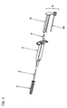
- a syringe generally comprises a syringe barrel 1, a hollow needle 2 and a plunger 3 comprising a plunger segment 31 and a plunger rod 35.
- the hollow needle 2 is protected by a removeable cover 21 and pellets of medicament are held in a medicament clamp 5.
- the syringe is supplied to the user already assembled and loaded with one or more medicament tablets.
- the hollow needle 2 is attached to one end of the syringe barrel 1.
- the plunger segment 31 and plunger rod 35 are assembled together telescopically collapsed and then inserted into the other end of the syringe barrel 1, leaving just the plunger handle 7 protruding outside the syringe barrel 1 and the protective cover 21 is placed over the needle 2.
- a user then pulls the plunger handle 7 to extend the telescopically arranged plunger segment 31 until it locks with the plunger rod 35 in its fully open position, by means of a catch arrangement 8, to form a rigid plunger 3.
- Plunger rod 35 and syringe barrel 1 also have a co-operating catch arrangement 6, to prevent the plunger rod 35 being entirely removed from the barrel 1, when the plunger 3 is extended.
- the catch arrangement 6, between the plunger rod 35 and the syringe barrel 1 ensures that the plunger rod 35 (and therefore the rigid plunger 3) is not pulled outside the syringe barrel 1, but remains within the barrel 1 aligned with the medicament tablets therein.
- the syringe barrel 1 is provided with a conventional flange 9, by which the user can support the barrel 1, whilst administering an injection.
- the user depresses the handle 7 of the plunger segment 31, which in turn drives the plunger rod 35 through the hollow needle 2, because the plunger segment 31 and plunger rod 35 are now rigidly coupled together.
- the catch arrangement 6 between the plunger rod 35 and syringe barrel 1 is released.
- a second catch arrangement 65 between the plunger rod 35 and the syringe barrel 1 engages, to lock the plunger 3 in its fully depressed.
- the plunger rod 35 extends the full length of the hollow needle 2 (and preferably a little past the end of the needle), to provide a blunt end 36 to the needle 2, to minimise the risk of needle stick injuries.
- the clamp 5 comprises a first portion 51 adapted to fit inside the hollow needle 2 and having a plurality of flexible fingers 52, which can expand slightly to allow a medicament pellet to be inserted into the clamp 5, but thereafter relax to their original configuration to clamp the medicament pellet firmly therein.
- the clamp 5 also comprises a second portion 55, which is too large to fit through the hollow needle 2, but is shaped to align the first portion 51 of the clamp 5 within the hollow needle 2.
- the second portion 55 of the clamp presents a tapered orifice 56 to the inside of the syringe barrel 1, to assist with alignment of the plunger rod 35 with the pellets of medicament held in the clamp 5.
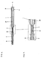
- FIGS. 6 and 7 show the arrangement of the telescopic plunger segment, rod, medicament clamp and pellets of medicament more clearly.
- the syringe is provided to the end user with a cover 21 shielding the exposed hollow needle 2, primed with medicament.
- the medicament pellets 10 are inserted into the clamp 5 and then dropped into the hollow needle 2 through the open end of the barrel 1.
- the plunger segment 31 and plunger rod 35 are assembled together in a collapsed telescopic configuration, with the plunger rod 35 lying within the plunger segment 31 (as shown in Figure 6).
- the plunger assembly 3 is then also inserted into the open end of the syringe barrel 1.
- the free end of the plunger rod 35 is aligned with the medicament pellets 10 in the clamp 5 and the other end of the plunger rod 35 is attached to the syringe barrel by means of the catch arrangement 6.
- the catch arrangement 6 comprises a resilient projection 36 extending from the plunger rod 35 (referenced in Figure 9), which engages in a slot 11 (referenced in Figure 9)in the syringe barrel 1.
- the resilient projection 36 has an engagement tooth, having a shallow sloping face 361 pointing towards the needle 2 and a steep or vertical flank 362, facing the exterior of the syringe barrel 1.
- the steep or vertical flank of the engagement tooth engages with the wall of the slot 11 in the syringe barrel 1, to prevent the plunger rod 35 from being pulled out of the barrel 1.
- a further catch arrangement 8 between the plunger segment 31 and plunder rod 35 engages to form a rigid plunger 3.
- the plunger rod 35 pushes the medicament tablets 10 through the clamp 5, through the hollow needle 2 and into the injection site.
- the syringe barrel is manufactured from a transparent material to allow a user of the syringe to see the medicament tablets stored therein. This avoids confusion between unused, primed syringes and used, empty syringes.
- the syringe barrel may be provided with a transparent window to achieve the same effect.
- the syringe barrel and plunger preferably has a polygonal shape to restrict the way they can be assembled together.
- the catches 6, 8 are preferably provided symmetrically on opposite sides of the barrel, to enable the plunger to be assembled in the barrel either way around.
Abstract
Description
- The present invention relates to a syringe device for subcutaneous injection of a pellet of medicament, such as those used during cancer treatment procedures. In particular, the invention provides a compact syringe device by use of a telescopic/locking plunger arrangement.
- According to the prior art, it is known to provide a syringe for subcutaneous injections, comprising a syringe barrel with a hollow needle attached thereto and a plunger, having a plunger rod capable of moving within the hollow needle, to drive the pellet of medicament through and out of the needle during the injection. Before the syringe is supplied to the user, one or more pellets of medicament are placed into the syringe barrel in alignment with the hollow needle. The plunger is then inserted into the barrel in its extended position, with the plunger rod taking up a position within the syringe barrel adjacent to the needle. A protective cover is then placed over the free end of the needle to protect the contents of the syringe. The plunger is maintained in this extended configuration by a locking collar, to prevent accidental activation of the syringe. Before first use, the user of the syringe removes the locking collar to enable the plunger to be depressed. The user then inserts the syringe needle under the skin as required and finally depresses the plunger. On depression of the plunger, the plunger rod drives one or more pellets of medicament through the hollow needle, to be deposited in the required location under the skin.
- A disadvantage of this type of arrangement is that the syringe, primed with medicament, is relatively long and cumbersome, because of the plunger's extended configuration. Furthermore, removal of the collar before first use, requires the use of two hands. Thus, and aim of the present invention is to provide a syringe for subcutaneous injection of a pellet of medicament that is compact and simple to operate.
- Accordingly, the present invention provides a syringe device comprising a barrel for holding one or more tablets of medicament, a hollow needle attached to the barrel and a plunger adapted to move within the barrel, the plunger having a plunger rod adapted to move within the hollow needle to drive a tablet of medicament through the needle, characterised in that
the plunger is composed of a plurality of segments, telescopically arranged one within the other, the plunger rod forming the innermost segment of the plunger, and each segment having a catch to lock the segment in its extended position. - An advantage of this telescoping / locking arrangement is that the syringe device is very compact and is wholly contained within the syringe barrel before first use, making it more robust and less likely to be damaged during transport. The total length of the syringe device (as supplied to the user) is only limited by the length of the plunger rod, which is itself limited only by the length of the hollow needle i.e. the plunger rod has to be of sufficient length to drive the medicament tablet through the full length of the needle and then out of its free end. Furthermore, by containing the whole plunger within the syringe barrel, the device is more robust and the plunger is less likely to be damaged during transport.
- The syringe device according to the invention is supplied to the user with the plunger segments in a telescopically collapsed condition i.e. lying one within another, the syringe needle attached to the syringe body and primed with medicament. On first use, the user of the syringe withdraws the plunger from the barrel and the plunger segments extend and lock together in their extended position. The plunger rod forms the innermost segment of the plunger and is locked inside the barrel by a catch. Thus, when the plunger segments are extended, the plunger rod is maintained within the barrel, aligned with the hollow needle.
- The catch arrangement between the plunger rod and the syringe barrel preferably comprises a resilient projection, which engages in a slot. The projection has a catch portion which has a shallow sloping face in the direction of movement of the plunger towards the hollow needle and a steep or vertical face in the direction of movement of the plunger away from the needle, towards the outside of the barrel. Thus, as the plunger segments are extended, the plunger rod is held in the syringe barrel by the catch arrangement, because of the engagement of the steep (or vertical) engagement face of the catch portion against the edge of the slot. Once the plunger segments are fully extended, they lock together forming a rigid plunger. The user then depresses the plunger and the catch between the plunger rod and the syringe barrel disengages (because the shallow sloping face of the catch portion slides past the edge of the slot allowing the catch to be released). The plunger rod is then depressed through the syringe needle, driving a tablet of medicament in front of it. When the medicament has been delivered, the user removes the syringe needle from the injection site. The plunger rod is fully depressed and extends the full length of the hollow needle (or slightly beyond the end of it), presenting a blunt end to the syringe and thereby preventing accidental needle stick injuries.
- Advantageously, the plunger rod is locked in its fully depressed position. This may be simply achieved by providing another catch at the needle end of the syringe barrel to prevent the plunger rod being withdrawn through the needle. In this arrangement, the resilient projection part of the catch arrangement is advantageously formed on the plunger rod and the slot is provided in the barrel. Thus, the second catch (to hold the plunger rod in its fully depressed position) is simply provided by a second slot, into which the resilient projection engages when the plunger is fully depressed.
- Another disadvantage of such conventional syringes having hollow needles is that the user of the syringe has to be careful to ensure the medicament is retained within the syringe needle until it is inserted under the skin. The hollow needle has to be large enough to allow the pellet of medicament to pass through it, without the user having to apply excessive force to the plunger. Thus, once the syringe is primed with medicament, a user has to be careful to hold the syringe substantially horizontal, otherwise the pellets of medicament can fall through then hollow needle and out of its open end once the cover is removed.
- In the present invention, this problem is overcome by the provision of a clamp, which has a first portion designed to slide inside the hollow needle and a second portion, which cannot fit inside the needle but is used to align the clamp with the needle. Preferably, the clamp is weighted to ensure that it drops into the needle and the second portion self aligns in the syringe barrel.
- Pellets of medicament are inserted into the clamp, then the clamp primed with the pellets is dropped into the open end of the syringe barrel and the clamp self aligns with the hollow needle. Finally the plunger is inserted in the barrel with the plunger rod aligned with the needle. The clamp is designed to be resilient so that it can expand to allow the pellets to be inserted and thereafter resumes its original configuration, to hold the pellets firmly therein. The resilience of the clamp may be provided by the use of a flexible elastic material or alternatively, the clamp may comprise a plurality of flexible fingers.
- Advantageously, the end of the clamp facing the barrel has a tapered orifice to assist in aligning the plunger rod with the pellets of medicament within the clamp. Thus, once the syringe is primed with medicament and the plunger is inserted into the syringe barrel, the plunger rod is held rigidly between the tapered orifice in the second portion of the clamp at one end and the catch arrangement between the plunger segments at the other end.
- The invention will now be described, by way of example only, with reference to the accompanying drawings, in which:
- FIGURE 1 shows an exploded isometric view of the syringe device according to the invention.
- FIGURE 2 shows a side view of the syringe device according to the invention, as supplied to a user, (before use).
- FIGURE 3 shows a side view of the syringe device shown in Figure 2, after the user has extended the plunger (ready for use).
- FIGURE 4 shows a side view of the syringe device shown in the previous figures with the plunger fully depressed by the user and the medicament ejected (after use).
- FIGURE 5 shows an isometric view of the medicament clamp according to the invention.
- FIGURE 6 shows a side section view through the syringe device shown in figure 2, as supplied to a user i.e. with the medicament tablets inserted in the medicament clamp, the clamp inserted into the syringe needle and the plunger in a telescopically collapsed configuration.
- FIGURE 7 shows an enlarged view of part of figure 6, detailing the medicament clamp with the pellets inserted therein.
- FIGURE 8 shows a side section view through the syringe device shown in figure 3, with the plunger fully extended.
- FIGURE 9 shows an enlarged view of part of figure 8, detailing the catch arrangement between the plunder segments.
-
- Referring to Figure 1, a syringe according to the invention generally comprises a
syringe barrel 1, ahollow needle 2 and a plunger 3 comprising aplunger segment 31 and aplunger rod 35. Thehollow needle 2 is protected by aremoveable cover 21 and pellets of medicament are held in amedicament clamp 5. - As shown in Figure 2, the syringe is supplied to the user already assembled and loaded with one or more medicament tablets. The
hollow needle 2 is attached to one end of thesyringe barrel 1. Theplunger segment 31 andplunger rod 35 are assembled together telescopically collapsed and then inserted into the other end of thesyringe barrel 1, leaving just the plunger handle 7 protruding outside thesyringe barrel 1 and theprotective cover 21 is placed over theneedle 2. - Referring to Figure 3, a user then pulls the
plunger handle 7 to extend the telescopically arrangedplunger segment 31 until it locks with theplunger rod 35 in its fully open position, by means of acatch arrangement 8, to form a rigid plunger 3.Plunger rod 35 andsyringe barrel 1 also have a co-operating catch arrangement 6, to prevent theplunger rod 35 being entirely removed from thebarrel 1, when the plunger 3 is extended. The catch arrangement 6, between theplunger rod 35 and thesyringe barrel 1, ensures that the plunger rod 35 (and therefore the rigid plunger 3) is not pulled outside thesyringe barrel 1, but remains within thebarrel 1 aligned with the medicament tablets therein. Thesyringe barrel 1 is provided with a conventional flange 9, by which the user can support thebarrel 1, whilst administering an injection. - Finally, as shown in Figure 4, the user depresses the
handle 7 of theplunger segment 31, which in turn drives theplunger rod 35 through thehollow needle 2, because theplunger segment 31 andplunger rod 35 are now rigidly coupled together. As the plunger 3 is depressed, the catch arrangement 6 between theplunger rod 35 andsyringe barrel 1 is released. When the plunger 3 is fully depressed, asecond catch arrangement 65 between theplunger rod 35 and thesyringe barrel 1 engages, to lock the plunger 3 in its fully depressed. In this position, theplunger rod 35 extends the full length of the hollow needle 2 (and preferably a little past the end of the needle), to provide ablunt end 36 to theneedle 2, to minimise the risk of needle stick injuries. - Referring to Figure 5, the medicament pellets are held in a specially designed
clamp 5 to prevent them falling through thehollow needle 2. Theclamp 5 comprises a first portion 51 adapted to fit inside thehollow needle 2 and having a plurality offlexible fingers 52, which can expand slightly to allow a medicament pellet to be inserted into theclamp 5, but thereafter relax to their original configuration to clamp the medicament pellet firmly therein. Theclamp 5 also comprises asecond portion 55, which is too large to fit through thehollow needle 2, but is shaped to align the first portion 51 of theclamp 5 within thehollow needle 2. Advantageously, thesecond portion 55 of the clamp presents atapered orifice 56 to the inside of thesyringe barrel 1, to assist with alignment of theplunger rod 35 with the pellets of medicament held in theclamp 5. - Now referring to figures 6 and 7, which show the arrangement of the telescopic plunger segment, rod, medicament clamp and pellets of medicament more clearly. As previously described, the syringe is provided to the end user with a
cover 21 shielding the exposedhollow needle 2, primed with medicament. Themedicament pellets 10 are inserted into theclamp 5 and then dropped into thehollow needle 2 through the open end of thebarrel 1. Theplunger segment 31 andplunger rod 35 are assembled together in a collapsed telescopic configuration, with theplunger rod 35 lying within the plunger segment 31 (as shown in Figure 6). The plunger assembly 3 is then also inserted into the open end of thesyringe barrel 1. The free end of theplunger rod 35 is aligned with themedicament pellets 10 in theclamp 5 and the other end of theplunger rod 35 is attached to the syringe barrel by means of the catch arrangement 6. - Referring to Figures 8 and 9, the catch arrangement 6 comprises a
resilient projection 36 extending from the plunger rod 35 (referenced in Figure 9), which engages in a slot 11 (referenced in Figure 9)in thesyringe barrel 1. Theresilient projection 36 has an engagement tooth, having a shallowsloping face 361 pointing towards theneedle 2 and a steep orvertical flank 362, facing the exterior of thesyringe barrel 1. In use, when the user pulls on the plunger handle 7 to extend the plunger 3, the steep or vertical flank of the engagement tooth engages with the wall of theslot 11 in thesyringe barrel 1, to prevent theplunger rod 35 from being pulled out of thebarrel 1. When theplunger segment 31 is fully extended, afurther catch arrangement 8 between theplunger segment 31 andplunder rod 35 engages to form a rigid plunger 3. - The user then depresses the plunger 3, to eject the
medicament tablet 10 from the end ofhollow needle 2. The shallowsloping face 361 of the engagement tooth, slides across the edge of theslot 11, allowing the plunger 3 to be depressed. The user may either insert thehollow needle 2 into the injection site before of after extending the plunger 3. When the plunger 3 is then depressed, theplunger rod 35, pushes themedicament tablets 10 through theclamp 5, through thehollow needle 2 and into the injection site. - Preferably, the syringe barrel is manufactured from a transparent material to allow a user of the syringe to see the medicament tablets stored therein. This avoids confusion between unused, primed syringes and used, empty syringes. Alternatively, the syringe barrel may be provided with a transparent window to achieve the same effect.
- For ease of assembly, the syringe barrel and plunger preferably has a polygonal shape to restrict the way they can be assembled together. Where the shape is rectangular (as shown in the drawings), the
catches 6, 8 are preferably provided symmetrically on opposite sides of the barrel, to enable the plunger to be assembled in the barrel either way around.
Claims (9)
- A syringe device comprising a barrel 1 for holding one or more tablets of medicament 10, a hollow needle 2 attached to the barrel 1 and a plunger 3 adapted to move within the barrel 1,
the plunger 3 having a plunger rod 35 adapted to move within the hollow needle 2 to drive a medicament tablet 10 through the needle,
characterised in that
the plunger 3 is composed of a plurality of segments, telescopically arranged one within the other,
the plunger rod 35 forming the innermost segment of the plunger 3, and
each segment having a catch 6, 8 to lock the segment in its extended position. - A syringe device according to claim 1, wherein the catch 6 on the plunger rod 35 is adapted to prevent the plunger rod 35 being removed from the barrel 1 but allows the rod 35 to be depressed through the barrel 1 once the segments are fully extended and locked together.
- A syringe device according to claim 2, wherein the catch 6 between the plunger rod 35 and the barrel 1 comprises a resilient projection 36 adapted to engage in a slot 11 and the projection has a smooth tapered face 361 in the direction of travel of the plunger rod 35 towards the free end of the needle 2 and a steep or vertical flank 362, which engages in the slot 11 when the plunger rod 35 is being pulled in a direction away from the needle 2.
- A syringe device according to any of the preceding claims, wherein the plunger 3 comprises a plunger rod 35 and a body segment 31 telescopically arranged with the plunger rod 35 inside the body segment 31.
- A syringe device according to any of the preceding claims, further comprising a clamp 5 adapted to firmly hold one or more medicament tablets 10 within the syringe barrel 1 and prevent the tablet 10 from falling through the hollow needle 2.
- A syringe device according to claim 5, wherein the clamp 5 is shaped to align the tablet with the hollow needle 2.
- A syringe device according to claim 5 or claim 6, wherein the clamp 5 is shaped to direct the plunger rod 35 towards the medicament tablet 10.
- A syringe device according to any one of claims 5 to 7, wherein the clamp 5 is weighted to fall in the correct orientation with respect to the hollow needle 2.
- A syringe device according to any of the preceding claims, wherein the plunger rod 35 is of sufficient length to extend the full length of the needle 2 when fully depressed.
Priority Applications (2)
| Application Number | Priority Date | Filing Date | Title |
|---|---|---|---|
| EP20010310573 EP1323450B1 (en) | 2001-12-18 | 2001-12-18 | Syringe device |
| DE2001605834 DE60105834T2 (en) | 2001-12-18 | 2001-12-18 | sprayer |
Applications Claiming Priority (1)
| Application Number | Priority Date | Filing Date | Title |
|---|---|---|---|
| EP20010310573 EP1323450B1 (en) | 2001-12-18 | 2001-12-18 | Syringe device |
Publications (2)
| Publication Number | Publication Date |
|---|---|
| EP1323450A1 true EP1323450A1 (en) | 2003-07-02 |
| EP1323450B1 EP1323450B1 (en) | 2004-09-22 |
Family
ID=8182547
Family Applications (1)
| Application Number | Title | Priority Date | Filing Date |
|---|---|---|---|
| EP20010310573 Expired - Lifetime EP1323450B1 (en) | 2001-12-18 | 2001-12-18 | Syringe device |
Country Status (2)
| Country | Link |
|---|---|
| EP (1) | EP1323450B1 (en) |
| DE (1) | DE60105834T2 (en) |
Cited By (15)
| Publication number | Priority date | Publication date | Assignee | Title |
|---|---|---|---|---|
| WO2007082889A1 (en) * | 2006-01-19 | 2007-07-26 | N.V. Organon | Kit for and method of assembling an applicator for inserting an implant |
| EP2072077A1 (en) | 2007-12-21 | 2009-06-24 | Rexam Pharma La Verpillière | Implant injection device |
| WO2009108847A1 (en) * | 2008-02-28 | 2009-09-03 | Becton, Dickinson And Company | Syringe with two piece plunger rod |
| WO2011022615A1 (en) * | 2009-08-21 | 2011-02-24 | Becton Dickinson France Sas | Syringe having a collapsible plunger rod |
| US7976510B2 (en) | 2008-02-28 | 2011-07-12 | Becton, Dickinson And Company | Syringe with adjustable two piece plunger rod |
| US8142390B2 (en) | 2007-05-07 | 2012-03-27 | Rexam Pharma Gmbh | Syringe device with an elongate plunger space |
| WO2013148447A1 (en) * | 2012-03-28 | 2013-10-03 | Warsaw Orthopedic, Inc. | Drug delivery system |
| US9039761B2 (en) | 2006-08-04 | 2015-05-26 | Allergan, Inc. | Ocular implant delivery assemblies with distal caps |
| USD835783S1 (en) | 2016-06-02 | 2018-12-11 | Intarcia Therapeutics, Inc. | Implant placement guide |
| USD860451S1 (en) | 2016-06-02 | 2019-09-17 | Intarcia Therapeutics, Inc. | Implant removal tool |
| US11413442B2 (en) | 2016-06-23 | 2022-08-16 | Warsaw Orthopedic, Inc. | Drug delivery device and methods having a retaining member |
| US11464958B2 (en) | 2014-07-25 | 2022-10-11 | Warsaw Orthopedic, Inc. | Drug delivery methods having an occluding member |
| US11478587B2 (en) | 2016-11-08 | 2022-10-25 | Warsaw Orthopedic, Inc. | Drug depot delivery system and method |
| US11504513B2 (en) | 2014-07-25 | 2022-11-22 | Warsaw Orthopedic, Inc. | Drug delivery device and methods having a retaining member |
| US11759614B2 (en) | 2015-11-23 | 2023-09-19 | Warsaw Orthopedic, Inc. | Enhanced stylet for drug depot injector |
Families Citing this family (3)
| Publication number | Priority date | Publication date | Assignee | Title |
|---|---|---|---|---|
| US8668676B2 (en) | 2006-06-19 | 2014-03-11 | Allergan, Inc. | Apparatus and methods for implanting particulate ocular implants |
| US8545554B2 (en) | 2009-01-16 | 2013-10-01 | Allergan, Inc. | Intraocular injector |
| US8529598B2 (en) | 2009-02-20 | 2013-09-10 | Boston Scientific Scimed, Inc. | Tissue puncture closure device |
Citations (7)
| Publication number | Priority date | Publication date | Assignee | Title |
|---|---|---|---|---|
| EP0292936A2 (en) * | 1987-05-26 | 1988-11-30 | Sumitomo Pharmaceuticals Company, Limited | Device for administering solid preparations |
| US4846793A (en) * | 1987-03-18 | 1989-07-11 | Endocon, Inc. | Injector for implanting multiple pellet medicaments |
| EP0564038A2 (en) * | 1992-03-30 | 1993-10-06 | Akzo Nobel N.V. | Implantation device |
| US5370628A (en) * | 1991-07-31 | 1994-12-06 | Allison; Alan C. | Safety needle and syringe |
| US5558637A (en) * | 1993-10-13 | 1996-09-24 | Leiras Oy | Implant injection device |
| DE19734385C1 (en) * | 1997-08-08 | 1999-02-18 | Gaplast Gmbh | Implant syringe |
| WO1999053991A1 (en) * | 1998-04-23 | 1999-10-28 | Alza Corporation | Trocar for inserting implants |
-
2001
- 2001-12-18 DE DE2001605834 patent/DE60105834T2/en not_active Expired - Lifetime
- 2001-12-18 EP EP20010310573 patent/EP1323450B1/en not_active Expired - Lifetime
Patent Citations (7)
| Publication number | Priority date | Publication date | Assignee | Title |
|---|---|---|---|---|
| US4846793A (en) * | 1987-03-18 | 1989-07-11 | Endocon, Inc. | Injector for implanting multiple pellet medicaments |
| EP0292936A2 (en) * | 1987-05-26 | 1988-11-30 | Sumitomo Pharmaceuticals Company, Limited | Device for administering solid preparations |
| US5370628A (en) * | 1991-07-31 | 1994-12-06 | Allison; Alan C. | Safety needle and syringe |
| EP0564038A2 (en) * | 1992-03-30 | 1993-10-06 | Akzo Nobel N.V. | Implantation device |
| US5558637A (en) * | 1993-10-13 | 1996-09-24 | Leiras Oy | Implant injection device |
| DE19734385C1 (en) * | 1997-08-08 | 1999-02-18 | Gaplast Gmbh | Implant syringe |
| WO1999053991A1 (en) * | 1998-04-23 | 1999-10-28 | Alza Corporation | Trocar for inserting implants |
Cited By (29)
| Publication number | Priority date | Publication date | Assignee | Title |
|---|---|---|---|---|
| US11040184B2 (en) | 2006-01-19 | 2021-06-22 | Merck Sharp & Dohme B.V. | Kit for and method of assembling an applicator for inserting an implant |
| JP2009523515A (en) * | 2006-01-19 | 2009-06-25 | ナムローゼ・フェンノートシャップ・オルガノン | Kit and method for assembling an applicator for inserting an implant |
| US10821277B2 (en) | 2006-01-19 | 2020-11-03 | Merck Sharp & Dohme B.V. | Kit for and method of assembling an applicator for inserting an implant |
| US10092739B2 (en) | 2006-01-19 | 2018-10-09 | Merck Sharp & Dohme B.V. | Kit for and method of assembling an applicator for inserting an implant |
| WO2007082889A1 (en) * | 2006-01-19 | 2007-07-26 | N.V. Organon | Kit for and method of assembling an applicator for inserting an implant |
| US9039761B2 (en) | 2006-08-04 | 2015-05-26 | Allergan, Inc. | Ocular implant delivery assemblies with distal caps |
| US8142390B2 (en) | 2007-05-07 | 2012-03-27 | Rexam Pharma Gmbh | Syringe device with an elongate plunger space |
| CN101687089B (en) * | 2007-05-07 | 2012-09-19 | 雷盛药物有限公司 | Syringe device with an elongate plunger space |
| US8834412B2 (en) * | 2007-12-21 | 2014-09-16 | Rexam Healthcare La Verpilliere | Device for injecting an implant |
| JP2009160395A (en) * | 2007-12-21 | 2009-07-23 | Rexam Pharma La Verpilliere | Implant injection device |
| EP2072077A1 (en) | 2007-12-21 | 2009-06-24 | Rexam Pharma La Verpillière | Implant injection device |
| US20090182267A1 (en) * | 2007-12-21 | 2009-07-16 | Gaetan Painchaud | Device for injecting an implant |
| US7976510B2 (en) | 2008-02-28 | 2011-07-12 | Becton, Dickinson And Company | Syringe with adjustable two piece plunger rod |
| US8801675B2 (en) | 2008-02-28 | 2014-08-12 | Becton Dickinson France, S.A.S. | Syringe with adjustable two piece plunger rod |
| US8172813B2 (en) | 2008-02-28 | 2012-05-08 | Becton, Dickinson And Company | Syringe with two piece plunger rod |
| WO2009108847A1 (en) * | 2008-02-28 | 2009-09-03 | Becton, Dickinson And Company | Syringe with two piece plunger rod |
| US8632519B2 (en) | 2009-08-21 | 2014-01-21 | Becton Dickinson France, S.A.S. | Syringe having a collapsible plunger rod |
| US9295783B2 (en) | 2009-08-21 | 2016-03-29 | Becton Dickinson France | Syringe having a collapsible plunger rod |
| WO2011022615A1 (en) * | 2009-08-21 | 2011-02-24 | Becton Dickinson France Sas | Syringe having a collapsible plunger rod |
| WO2013148447A1 (en) * | 2012-03-28 | 2013-10-03 | Warsaw Orthopedic, Inc. | Drug delivery system |
| US11504513B2 (en) | 2014-07-25 | 2022-11-22 | Warsaw Orthopedic, Inc. | Drug delivery device and methods having a retaining member |
| US11464958B2 (en) | 2014-07-25 | 2022-10-11 | Warsaw Orthopedic, Inc. | Drug delivery methods having an occluding member |
| US11759614B2 (en) | 2015-11-23 | 2023-09-19 | Warsaw Orthopedic, Inc. | Enhanced stylet for drug depot injector |
| USD840030S1 (en) | 2016-06-02 | 2019-02-05 | Intarcia Therapeutics, Inc. | Implant placement guide |
| USD962433S1 (en) | 2016-06-02 | 2022-08-30 | Intarcia Therapeutics, Inc. | Implant placement guide |
| USD860451S1 (en) | 2016-06-02 | 2019-09-17 | Intarcia Therapeutics, Inc. | Implant removal tool |
| USD835783S1 (en) | 2016-06-02 | 2018-12-11 | Intarcia Therapeutics, Inc. | Implant placement guide |
| US11413442B2 (en) | 2016-06-23 | 2022-08-16 | Warsaw Orthopedic, Inc. | Drug delivery device and methods having a retaining member |
| US11478587B2 (en) | 2016-11-08 | 2022-10-25 | Warsaw Orthopedic, Inc. | Drug depot delivery system and method |
Also Published As
| Publication number | Publication date |
|---|---|
| DE60105834T2 (en) | 2005-10-06 |
| EP1323450B1 (en) | 2004-09-22 |
| DE60105834D1 (en) | 2004-10-28 |
Similar Documents
| Publication | Publication Date | Title |
|---|---|---|
| EP1323450A1 (en) | Syringe device | |
| US10765809B2 (en) | Auto-injector for epinephrine injection | |
| US11484667B2 (en) | Medicament delivery device | |
| EP1660158B1 (en) | Syringe with automatically triggered safety sleeve | |
| US6776777B2 (en) | Passive safety shield system for injection devices | |
| ES2301638T3 (en) | SECURITY PROTECTIVE SYSTEM FOR PRE-FILLED SYRINGES. | |
| US8070741B2 (en) | Safety shield system for prefilled syringe | |
| TWI551317B (en) | Auto-injector | |
| EP2313135B1 (en) | A retractable syringe | |
| US5273541A (en) | Safety syringe | |
| US6991618B2 (en) | Single use syringe and plunger rod locking device therefor | |
| US20180161521A1 (en) | Safety Needle Devices | |
| KR102024445B1 (en) | Medicament injection device | |
| US10661020B2 (en) | Medication delivery device | |
| JP2003522609A (en) | Automatically actuated safety shield system for syringes | |
| EP3188772A1 (en) | Automatic injection device with variable dosing | |
| JP6495329B2 (en) | Shielding mechanism for injection devices | |
| KR102342500B1 (en) | Safety syringe protection cap | |
| EP0637256B1 (en) | An improved parenteral device | |
| CN209378203U (en) | Needle assembles equipment | |
| AU2012101441A4 (en) | Syringe Safety Prefillable | |
| JP2023052861A (en) | Reuse-prevention safety catheter | |
| CN109966596A (en) | Needle assembles equipment |
Legal Events
| Date | Code | Title | Description |
|---|---|---|---|
| PUAI | Public reference made under article 153(3) epc to a published international application that has entered the european phase |
Free format text: ORIGINAL CODE: 0009012 |
|
| 17P | Request for examination filed |
Effective date: 20021211 |
|
| AK | Designated contracting states |
Designated state(s): AT BE CH CY DE DK ES FI FR GB GR IE IT LI LU MC NL PT SE TR |
|
| AX | Request for extension of the european patent |
Extension state: AL LT LV MK RO SI |
|
| RAP1 | Party data changed (applicant data changed or rights of an application transferred) |
Owner name: REXAM PHARMA GMBH |
|
| GRAP | Despatch of communication of intention to grant a patent |
Free format text: ORIGINAL CODE: EPIDOSNIGR1 |
|
| AKX | Designation fees paid |
Designated state(s): BE CH DE FR GB LI |
|
| GRAS | Grant fee paid |
Free format text: ORIGINAL CODE: EPIDOSNIGR3 |
|
| GRAA | (expected) grant |
Free format text: ORIGINAL CODE: 0009210 |
|
| AK | Designated contracting states |
Kind code of ref document: B1 Designated state(s): BE CH DE FR GB LI |
|
| REG | Reference to a national code |
Ref country code: GB Ref legal event code: FG4D |
|
| REG | Reference to a national code |
Ref country code: CH Ref legal event code: EP |
|
| REG | Reference to a national code |
Ref country code: IE Ref legal event code: FG4D |
|
| REF | Corresponds to: |
Ref document number: 60105834 Country of ref document: DE Date of ref document: 20041028 Kind code of ref document: P |
|
| REG | Reference to a national code |
Ref country code: CH Ref legal event code: NV Representative=s name: HANS RUDOLF GACHNANG PATENTANWALT |
|
| PLBE | No opposition filed within time limit |
Free format text: ORIGINAL CODE: 0009261 |
|
| STAA | Information on the status of an ep patent application or granted ep patent |
Free format text: STATUS: NO OPPOSITION FILED WITHIN TIME LIMIT |
|
| ET | Fr: translation filed | ||
| 26N | No opposition filed |
Effective date: 20050623 |
|
| PGFP | Annual fee paid to national office [announced via postgrant information from national office to epo] |
Ref country code: BE Payment date: 20121030 Year of fee payment: 12 |
|
| BERE | Be: lapsed |
Owner name: *REXAM PHARMA G.M.B.H. Effective date: 20131231 |
|
| PG25 | Lapsed in a contracting state [announced via postgrant information from national office to epo] |
Ref country code: BE Free format text: LAPSE BECAUSE OF NON-PAYMENT OF DUE FEES Effective date: 20131231 |
|
| REG | Reference to a national code |
Ref country code: FR Ref legal event code: PLFP Year of fee payment: 16 |
|
| REG | Reference to a national code |
Ref country code: FR Ref legal event code: PLFP Year of fee payment: 17 |
|
| PGFP | Annual fee paid to national office [announced via postgrant information from national office to epo] |
Ref country code: FR Payment date: 20171219 Year of fee payment: 17 |
|
| PGFP | Annual fee paid to national office [announced via postgrant information from national office to epo] |
Ref country code: CH Payment date: 20171221 Year of fee payment: 17 Ref country code: GB Payment date: 20171221 Year of fee payment: 17 |
|
| PGFP | Annual fee paid to national office [announced via postgrant information from national office to epo] |
Ref country code: DE Payment date: 20180117 Year of fee payment: 17 |
|
| REG | Reference to a national code |
Ref country code: DE Ref legal event code: R119 Ref document number: 60105834 Country of ref document: DE |
|
| REG | Reference to a national code |
Ref country code: CH Ref legal event code: PL |
|
| GBPC | Gb: european patent ceased through non-payment of renewal fee |
Effective date: 20181218 |
|
| PG25 | Lapsed in a contracting state [announced via postgrant information from national office to epo] |
Ref country code: FR Free format text: LAPSE BECAUSE OF NON-PAYMENT OF DUE FEES Effective date: 20181231 Ref country code: DE Free format text: LAPSE BECAUSE OF NON-PAYMENT OF DUE FEES Effective date: 20190702 |
|
| PG25 | Lapsed in a contracting state [announced via postgrant information from national office to epo] |
Ref country code: GB Free format text: LAPSE BECAUSE OF NON-PAYMENT OF DUE FEES Effective date: 20181218 Ref country code: CH Free format text: LAPSE BECAUSE OF NON-PAYMENT OF DUE FEES Effective date: 20181231 Ref country code: LI Free format text: LAPSE BECAUSE OF NON-PAYMENT OF DUE FEES Effective date: 20181231 |