EP1322875B1 - Belt tensioner - Google Patents
Belt tensioner Download PDFInfo
- Publication number
- EP1322875B1 EP1322875B1 EP01973648A EP01973648A EP1322875B1 EP 1322875 B1 EP1322875 B1 EP 1322875B1 EP 01973648 A EP01973648 A EP 01973648A EP 01973648 A EP01973648 A EP 01973648A EP 1322875 B1 EP1322875 B1 EP 1322875B1
- Authority
- EP
- European Patent Office
- Prior art keywords
- carrier
- tensioner
- track
- shoe
- damping
- Prior art date
- Legal status (The legal status is an assumption and is not a legal conclusion. Google has not performed a legal analysis and makes no representation as to the accuracy of the status listed.)
- Expired - Lifetime
Links
Images


Classifications
-
- F—MECHANICAL ENGINEERING; LIGHTING; HEATING; WEAPONS; BLASTING
- F16—ENGINEERING ELEMENTS AND UNITS; GENERAL MEASURES FOR PRODUCING AND MAINTAINING EFFECTIVE FUNCTIONING OF MACHINES OR INSTALLATIONS; THERMAL INSULATION IN GENERAL
- F16H—GEARING
- F16H7/00—Gearings for conveying rotary motion by endless flexible members
- F16H7/08—Means for varying tension of belts, ropes, or chains
- F16H7/10—Means for varying tension of belts, ropes, or chains by adjusting the axis of a pulley
- F16H7/12—Means for varying tension of belts, ropes, or chains by adjusting the axis of a pulley of an idle pulley
- F16H7/1209—Means for varying tension of belts, ropes, or chains by adjusting the axis of a pulley of an idle pulley with vibration damping means
- F16H7/1218—Means for varying tension of belts, ropes, or chains by adjusting the axis of a pulley of an idle pulley with vibration damping means of the dry friction type
-
- F—MECHANICAL ENGINEERING; LIGHTING; HEATING; WEAPONS; BLASTING
- F16—ENGINEERING ELEMENTS AND UNITS; GENERAL MEASURES FOR PRODUCING AND MAINTAINING EFFECTIVE FUNCTIONING OF MACHINES OR INSTALLATIONS; THERMAL INSULATION IN GENERAL
- F16H—GEARING
- F16H7/00—Gearings for conveying rotary motion by endless flexible members
- F16H7/08—Means for varying tension of belts, ropes, or chains
- F16H2007/0802—Actuators for final output members
- F16H2007/0808—Extension coil springs
-
- F—MECHANICAL ENGINEERING; LIGHTING; HEATING; WEAPONS; BLASTING
- F16—ENGINEERING ELEMENTS AND UNITS; GENERAL MEASURES FOR PRODUCING AND MAINTAINING EFFECTIVE FUNCTIONING OF MACHINES OR INSTALLATIONS; THERMAL INSULATION IN GENERAL
- F16H—GEARING
- F16H7/00—Gearings for conveying rotary motion by endless flexible members
- F16H7/08—Means for varying tension of belts, ropes, or chains
- F16H7/0829—Means for varying tension of belts, ropes, or chains with vibration damping means
- F16H2007/084—Means for varying tension of belts, ropes, or chains with vibration damping means having vibration damping characteristics dependent on the moving direction of the tensioner
-
- F—MECHANICAL ENGINEERING; LIGHTING; HEATING; WEAPONS; BLASTING
- F16—ENGINEERING ELEMENTS AND UNITS; GENERAL MEASURES FOR PRODUCING AND MAINTAINING EFFECTIVE FUNCTIONING OF MACHINES OR INSTALLATIONS; THERMAL INSULATION IN GENERAL
- F16H—GEARING
- F16H7/00—Gearings for conveying rotary motion by endless flexible members
- F16H7/08—Means for varying tension of belts, ropes, or chains
- F16H2007/0889—Path of movement of the finally actuated member
- F16H2007/0891—Linear path
Definitions
- This invention relates generally to a tensioner for tensioning a belt of a belt drive system. More particularly, it relates to a tensioner having a linear pulley movement. Specifically, this invention relates to a linear movement tensioner having a mechanical damping mechanism.
- the present invention has as an object the provision of a linear movement tensioner that is simple and compact.
- the present invention has as a further object the provision of a linear movement tensioner with a mechanical damping mechanism having asymmetrical damping properties.
- the present invention has as a further object the provision of a linear movement tensioner with a mechanical damping mechanism having parasitic torque compensating properties to enhance tensioner durability and operation.
- the invention is an improved tensioner for tensioning a power transmission belt.
- the tensioner is of the type having a track, a carrier mounted in sliding relation with the track with two degrees freedom of movement, a pulley rotatably mounted upon the carrier and for engaging the power transmission belt, a spring biasing the carrier in longitudinal relation to the track, and a damping mechanism that modifies the biasing of the spring based upon movement of the carrier in relation to the track.
- the damping mechanism having a shoe placed in asymmetrical damping relation to the carrier and the track. Further, the shoe includes a first friction bearing surface in mating relationship with a second friction bearing surface of the track.
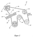
- Figure 1 depicts a typical accessory drive system 10 for an automotive internal combustion engine in which the tensioner 26 of the instant invention can be employed.
- Alternator pulley 14 is depicted to be mounted upon alternator 12.
- System 10 includes alternator pulley 14, power steering pump pulley 18, water pump pulley 20, crankshaft pulley 22, power transmission belt 24, and tensioner 26.
- Tensioner 26 includes first end support 30 and second end support 32 which serve to close the ends of track 28 and as points for mounting directly or indirectly to the internal combustion engine (not depicted).
- Tensioner 26 is shown to be in contact with belt 24 via tensioner pulley 48 at a span where power transmission belt 24 departs crankshaft pulley 22 when belt 24 traveling in the direction of normal operation as shown by the arrow labeled "Belt Travel". During normal operation of system 10, this is the span with the least tension. This is merely a typical location. Any other span may be selected, depending upon the requirements associated with the particular application.
- Tensioner pulley 48 follows a linear travel along track 28, described in greater detail below. It is preferred that the linear path be oriented perpendicular to the path the associated span would assume if taut between the pulleys at either end of the span, in this case alternator pulley 14 and crankshaft pulley 22, but for the presence of tensioner 26. This orientation minimizes the movement of tensioner pulley 48 for any given belt deflection, thus reducing the necessary length of track 28 and allowing tensioner 26 to be more compact overall, and improves the force relationships within tension 26 to allow optimal longevity of the internal features of tensioner 26. However, it is recognized that certain applications may not allow this orientation. Satisfactory results may still be obtained in those applications.
- first end support 30 includes first attachment holes 42 to accept fasteners, not depicted, for attaching tensioner 26 to the engine.
- Second end support 32 includes second attachment holes 44 to accept fasteners, not depicted, for attaching tensioner 26 to the engine. It can be seen that the portions of first end support 30, having first attachment holes 42, and second end support 32 having second attachment holes 44 each project away from tensioner pulley 48 and have bottom surfaces approximately aligned on the same plane as the bottom surface of tensioner pulley 48.
- Track 28 includes carrier support channels 58 and damping channel 60.
- Carrier 46 includes carrier bearings 56, which ride within carrier support channels 58.
- Tensioner pulley 48 is rotatably affixed to carrier 46 by and journaled upon bolt 50 via ball bearing assembly including races 52 and balls 54.
- Carrier 46 also includes angled block 62, which may be by integral casting or by joining of separate pieces.
- Shoe 66 is placed upon carrier 46 and about angled block 62 in a manner that allows shoe 66 to slide over angled block 62 at angled junction 64.
- Shoe 66 includes shoe bearing 68, which rides within damping channel 60.
- Shoe 66 has moveable spring loop 70 through which first spring hook 80 attaches.
- Second spring hook 82 is found at the opposite end of spring 72 and attaches through fixed spring loop 74, which forms part of second end support 32.
- tensioner pulley 48 with bearing comprising races 52 and balls 54 is bolted upon carrier 46, carrier bearings 56 are affixed in place, and shoe 66 with shoe bearing 68 attached are placed upon carrier 46 (carrier assembly 71) spring 72 is attached at moveable spring loop 70 and carrier assembly 71 is inserted into track 28.
- Carrier bearings 56 mate with carrier support channels 58 to create a low friction junction that. allows only substantially longitudinal movement of the assembly, within track 28.
- the relationship between carrier bearings 56 and carrier support channels 58 determine the two degrees of freedom of movement of carrier assembly 71.
- First and second end supports 30 and 32 and first and second end caps 34 and 36 are placed over the ends of track 28. Fasteners (not depicted) are then inserted through first and second cap attachment points 38 and 40, respectively, and compatible threaded openings in first and second end supports 30 and 32 and track 28 to join all five items. Second spring hook 82 is then inserted through fixed spring loop 74 to complete assembly of tensioner 26.
- the length of track 28 is commonly chosen to accommodate the full range of motion required of carrier assembly 71 to respond to changing conditions of system 10.
- first end support 30 can include a stop function to limit the longitudinal travel of carrier assembly 71 for those applications that can benefit from limited tensioner travel. In such case, a stop can be added to first end support 30 and carrier assembly 71, not depicted. Further, track 28 would be sized accordingly.
- Tensioner 26 is then affixed to the engine.
- Carrier assembly 71 is then restrained at or near the limit of its travel causing spring 72 to elongate and allowing belt 24 to be trained about the working pulleys comprising alternator pulley 14, power steering pump pulley 16, air conditioning compressor pulley 18, water pump pulley 20, and crankshaft pulley 22, and tensioner pulley 48 in the manner depicted in Figure 1.
- Static tension is the result of the force applied to power transmission belt 24 by tensioner 26 via tensioner pulley 48 being biased in the belt tensioning direction with the effect of tending to lengthen the distance power transmission belt 24 is forced to travel about all of the pulleys 14, 16, 18, 20, 22, 24, and 48. If it were assumed that each of the pulleys 14, 16, 18, 20, 22, 24, and 48 is allowed to rotate freely, tension on every span would be the same and at static tension. However, variable torque upon each of the working pulleys 14, 16, 18, 20, and 22 causes tension upon the span in contact with tensioner pulley 48 to vary in an oscillatory manner. Carrier assembly 71 reacts commensurately.
- Dynamic tension is the tension over the length of belt 24 that is the result of static tension as altered by the influences of various imbalances and of torque upon each pulley 14, 16, 18, 20, 22, and 24, and as altered by the reaction of tensioner 26 to those influences.
- Asymmetrical damping is particularly effective in compensating for oscillatory tension.
- asymmetrical damping is where the damping level for one direction of movement of carrier assembly 71 is significantly different from the damping level in the other direction of movement.
- damping is greater when carrier assembly 71 is moving in the belt loosening direction than when carrier 71 is moving in the belt tensioning direction.
- damping for tensioner 26 is provided by the damping elements comprising damping channel 60, angled block 62, angled junction 64, shoe 66, and shoe bearing 68.
- damping channel 60 angled block 62, angled junction 64, shoe 66, and shoe bearing 68.
- the angle X of angled junction 64 is approximately 45°.
- Angle X can be adjusted to alter the level of damping asymmetry to accommodate differing applications. As angle X approaches 90°, asymmetry approaches zero. Asymmetry rises as angle X diminishes. However, there is point at which too low an angle X results in a non-functioning tensioner, due to jamming of the mechanism or degradation of structural integrity.
- Placement of angled block 62 determines the location of downward force F and vertical component A"'. If angled block 62 were placed upon carrier 46 such that placement of vertical component A"' coincided with the far right edge of carrier bearings 56, then the immediately preceding discussion that ignored the effects of downward force F and vertical component A"' would apply to tensioner 26. However, as angled block 64 is placed more to the left of carrier 46, it increasingly displaces the function of second leveling force E. This effect is significant in two aspects. One, once second leveling force E is completely displaced by vertical component A"', the tendency for increased wear at the upper left portion of carrier bearings 56 is essentially eliminated. Two, second leveling force E only exists when carrier bearings 56 is in contact with carrier support channels 58.
- carrier 46 twists increasingly far before second leveling force E participates in leveling carrier 46 within carrier support channels 58.
- Vertical component A"' is not dependant in that fashion and is present at all times that spring force A is present.
- vertical component A"' is left of the lower right edge of carrier bearings 56, it acts to level carrier 46 at all times that spring force A is present, tending to maintain carrier 46 level to track 28 and tending eliminate the uneven wear pattern and improve durability carrier bearings 56.
- angled block 62 can be placed anywhere within the left and right extremes of carrier 46, or even extended beyond its depicted longitudinal boundaries, and achieve a working tensioner 26. However, it is preferred to place angled block 62 at a point where the wear along the lower portion of carrier bearings 56, that normally make contact with carrier support channels 58, is substantially uniform. This is a function of the magnitude of moment C, placement and magnitude of damping forces G and H, length of carrier bearings 56, coefficient of friction between carrier bearings 56 and carrier support channels 58, angle of angle X, coefficient of friction at angled junction 64, surface area of angled junction 64, and other factors.
- Shoe friction bearing surface 76 and track friction bearing surface 78 shapes affect placement and magnitude of damping forces G and H.
- they are truncated nested V's and not only perform friction control so as to affect forces G and H, but also perform a longitudinal alignment function between track 28 and shoe 66.
- Various other shapes are contemplated including nested V's, a plurality of nested V's or truncated nested V's. Substantially rectangular shapes are also contemplated.
- various shapes and contours can be chosen for the surfaces at angled junction 64.
- the surfaces are flat and substantially rectangular. Having the surfaces as nested V's or a plurality of nested V's, similar to the working surfaces of a v-ribbed belt and associated pulley, can be incorporated to control frictional properties at angled junction 64.
- the nested V's singularly or plurally, can also provide a longitudinal alignment function between carrier 46 and shoe 66.
- Various bearing configurations can be interposed at angled junction 64, including friction reducing materials, lubricants, ball bearing assemblies, or roller bearing assemblies.
- the preferred embodiment depicted in the Figures allows a compact tensioner with linear movement.
- the inclusion of mechanical damping, as opposed to hydraulic, allows both its compact size and avoidance of the disadvantages of the inclusion of hydraulics.
- the mechanical damping mechanism is sophisticated to the point of allowing asymmetrical damping over a substantial range of asymmetry and of enhancing overall tensioner 26 durability without complicated and expensive bearing assemblies at the interface of track 28 and carrier 46.
- Tensioner 26 is shown in one preferred embodiment to include spring 72 operating under tension and directly between second end support 32 and shoe 66 and within damping channel 60.
- spring 72 can be located outside of damping channel 60, with a cable and pulley or other mechanism to communicate tensile spring force from outside damping channel 60 to inside damping channel 60 and onto moveable spring loop 70. This allows the length of spring 72 to mostly coincide with the over all longitudinal dimension of carrier assembly 71, and thereby reduce the necessary length of track 28 and thus tensioner 26.
- a torsion spring can replace the depicted tensile spring 72, whether inside or outside of damping channel 60. It is merely necessary to convert the rotary motion of a torsion spring to a linear motion via a cable connection or other well-known mechanism. Further, abutting relationships can be made on the right side of first end support 30 and the left side of shoe 66 to support a compression spring, without disturbing the significant force relationships regarding damping asymmetry and wear pattern improvement.
- the compression spring can either augment or replace tensile spring 72.
Abstract
Description
Claims (7)
- A tensioner (26) for tensioning a power transmission belt (24) of the type having a track (28), a carrier (46) mounted in sliding relation with said track with two degrees freedom of movement, a pulley (48) rotatably mounted upon said carrier and for engaging said power transmission belt, a spring (72) biasing said carrier in longitudinal relation to said track, and a damping mechanism (60, 62, 64, 66, 68) that modifies the biasing of said spring based upon movement of said carrier in relation to said track, characterised in that
said damping mechanism including a shoe (66) placed in asymmetrical damping relation to said carrier and said track, and including a first friction bearing surface in mating relationship with a second friction bearing surface of said track. - The tensioner of claim 1, further comprising:said asymmetrical damping relation being said shoe in mechanical communication with said carrier and urged toward said track upon movement of said carrier in one degree of movement.
- The tensioner of claim 2, further comprising:said mechanical communication including an angled junction (64) between said carrier and said shoe.
- The tensioner claim 2, further comprising:said mechanical communication including at least one swing-arm between said carrier and said shoe.
- The tensioner of claim 2, further comprising:said mechanical communication including a pivot between said carrier and said shoe.
- The tensioner of claim 1, further comprising:said shoe being in direct mechanical communication with said spring.
- The tensioner of claim 1, further comprising:said damping mechanism including torque compensation.
Applications Claiming Priority (3)
| Application Number | Priority Date | Filing Date | Title |
|---|---|---|---|
| US23762500P | 2000-10-03 | 2000-10-03 | |
| US237625P | 2000-10-03 | ||
| PCT/US2001/030773 WO2002029283A2 (en) | 2000-10-03 | 2001-10-01 | Belt tensioner |
Publications (2)
| Publication Number | Publication Date |
|---|---|
| EP1322875A2 EP1322875A2 (en) | 2003-07-02 |
| EP1322875B1 true EP1322875B1 (en) | 2005-03-09 |
Family
ID=22894498
Family Applications (1)
| Application Number | Title | Priority Date | Filing Date |
|---|---|---|---|
| EP01973648A Expired - Lifetime EP1322875B1 (en) | 2000-10-03 | 2001-10-01 | Belt tensioner |
Country Status (16)
| Country | Link |
|---|---|
| US (1) | US6743132B2 (en) |
| EP (1) | EP1322875B1 (en) |
| JP (1) | JP4080327B2 (en) |
| KR (1) | KR100570933B1 (en) |
| CN (1) | CN1318781C (en) |
| AT (1) | ATE290665T1 (en) |
| AU (1) | AU2001293204A1 (en) |
| BR (1) | BR0114363A (en) |
| CA (1) | CA2421841C (en) |
| DE (1) | DE60109309T2 (en) |
| ES (1) | ES2240523T3 (en) |
| HK (1) | HK1052960A1 (en) |
| MX (1) | MXPA03003934A (en) |
| PL (1) | PL366099A1 (en) |
| RU (1) | RU2240453C1 (en) |
| WO (1) | WO2002029283A2 (en) |
Families Citing this family (24)
| Publication number | Priority date | Publication date | Assignee | Title |
|---|---|---|---|---|
| MXPA03003937A (en) * | 2000-10-03 | 2003-08-19 | Gates Corp | Dual linear belt tensioner. |
| KR100470584B1 (en) * | 2002-11-06 | 2005-03-08 | 삼성전자주식회사 | apparatus for fixing a driven pully in an office mchine |
| GB0407089D0 (en) * | 2004-03-30 | 2004-05-05 | Ford Global Tech Llc | An engine belt drive system |
| US20060052194A1 (en) * | 2004-09-03 | 2006-03-09 | Gerring Douglas G | Torsional force linear tensioner |
| TWI248758B (en) * | 2004-09-21 | 2006-02-01 | Avision Inc | Resilient device capable of preventing excessive deformation caused by external load |
| WO2007075844A1 (en) * | 2005-12-20 | 2007-07-05 | Intuitive Surgical, Inc. | Telescoping insertion axis of a robotic surgical system |
| US8603249B2 (en) * | 2006-12-11 | 2013-12-10 | Lg Electronics Inc. | Lift pin driving device and manufacturing apparatus having same |
| CN101377231B (en) * | 2008-09-01 | 2011-05-18 | 广州市科利亚农业机械有限公司 | Tension device for packing auger drive belt |
| CN102261441B (en) * | 2010-05-31 | 2014-01-15 | 鸿富锦精密工业(深圳)有限公司 | Speed reducer |
| US8974332B2 (en) * | 2012-08-23 | 2015-03-10 | Patton's Medical, Llc | Adjustment device |
| RU2523534C2 (en) * | 2012-11-14 | 2014-07-20 | Леонид Федорович Мечкало | Indicator of flexible gearing tension |
| WO2014183200A1 (en) | 2013-05-14 | 2014-11-20 | Litens Automotive Partnership | Tensioner with improved damping |
| CN103267096A (en) * | 2013-05-14 | 2013-08-28 | 佛山市保利来建材实业有限公司 | Flexible chain tensioning structure |
| CN103317395A (en) * | 2013-06-24 | 2013-09-25 | 苏州快吉刀片制造有限公司 | Blade grinding system |
| CN106246837B (en) * | 2015-06-12 | 2019-03-26 | 内蒙古欧意德发动机有限公司 | Attachment support frame and generator system in transmission system |
| CN105035202B (en) * | 2015-08-17 | 2017-08-29 | 深圳先进技术研究院 | Ship wall-climbing robot for removing rust |
| CN106402301A (en) * | 2016-11-14 | 2017-02-15 | 江苏中利石化设备有限公司 | Radial spring expansion device |
| US20180172126A1 (en) * | 2016-12-16 | 2018-06-21 | Greg Zahner | Method and apparatus for power distribution |
| US11261945B1 (en) * | 2017-06-22 | 2022-03-01 | Board Of Trustees Of The University Of Alabama, For And On Behalf Of The University Of Alabama In Huntsville | Coupling system for reducing fatigue and dynamic amplification of loads in objects |
| CN107387693B (en) * | 2017-09-21 | 2023-06-20 | 无锡永凯达齿轮有限公司 | Belt tensioner with unidirectional high damping automatic compensation |
| US11359710B1 (en) * | 2018-06-01 | 2022-06-14 | Hudson Products Corporation | Drive belt tensioning system for air-cooled heat exchangers |
| CN110255075A (en) * | 2019-05-07 | 2019-09-20 | 湖北迪迈威智能装备有限公司 | A kind of transmission roller channel and Transmission system |
| US11293529B2 (en) * | 2019-05-20 | 2022-04-05 | Deere & Company | Snowblower belt drive system |
| US11536350B1 (en) | 2021-06-28 | 2022-12-27 | Lennox Industries Inc. | Tensioning systems and methods |
Family Cites Families (21)
| Publication number | Priority date | Publication date | Assignee | Title |
|---|---|---|---|---|
| US1783987A (en) * | 1929-02-19 | 1930-12-09 | Morse Chain Co | Chain-adjusting device |
| US3413866A (en) * | 1966-10-14 | 1968-12-03 | Byron C. Ford | Belt tensioning device |
| JPS56143850A (en) * | 1980-04-09 | 1981-11-09 | Nippon Soken Inc | Belt tension control device |
| US4728317A (en) | 1981-08-27 | 1988-03-01 | Dayco Products, Inc. | Belt tensioner, part therefor and methods of making the same |
| US4696664A (en) | 1981-08-27 | 1987-09-29 | Dayco Products, Inc. | Belt tensioning means |
| US4767385A (en) | 1981-08-27 | 1988-08-30 | Dayco Products, Inc. | Belt tensioning means |
| US4509935A (en) * | 1981-08-27 | 1985-04-09 | Dayco Corporation | Belt tensioner and method of making the same |
| US4500304A (en) | 1981-09-11 | 1985-02-19 | Dayco Corporation | Belt tensioner |
| US4624652A (en) | 1982-06-25 | 1986-11-25 | Dayco Corporation | Belt tensioner, part therefor and methods of making the same |
| US4634408A (en) | 1981-09-11 | 1987-01-06 | Dayco Corporation | Belt tensioner, part therefor and methods of making the same |
| US4708697A (en) | 1981-09-11 | 1987-11-24 | Dayco Products, Inc. | Belt tensioner, part therefor and methods of making the same |
| US4425103A (en) | 1981-09-11 | 1984-01-10 | Dayco Corporation | Belt tensioner, part therefor and methods of making the same |
| US4601683A (en) | 1982-06-25 | 1986-07-22 | Dayco Corporation | Belt tensioner, part therefor and methods of making the same |
| US4969859A (en) * | 1989-10-24 | 1990-11-13 | Pitney Bowes Inc. | Belt tensioning apparatus |
| DE4203448A1 (en) * | 1992-02-07 | 1993-08-12 | Schaeffler Waelzlager Kg | Belt tensioning device for the drive of secondary assemblies in engines - has gap in vibration dampener between piston and friction body |
| DE4203449A1 (en) * | 1992-02-07 | 1993-08-12 | Schaeffler Waelzlager Kg | Belt tensioning device for the drive of secondary assemblies of engines - has friction body formed by two wedged piston parts set axially in succession |
| US5439420A (en) * | 1994-04-04 | 1995-08-08 | Ford Motor Company | Accessory drive system for an automotive engine |
| DE29610404U1 (en) * | 1996-06-13 | 1996-08-22 | Winklhofer & Soehne Gmbh | Damping ring |
| US5924947A (en) * | 1997-07-23 | 1999-07-20 | Ford Global Technologies, Inc. | Asymmetrically hydraulically damped drivebelt tensioner for automotive engine |
| US5951423A (en) * | 1997-10-08 | 1999-09-14 | Borg-Warner Automotive, Inc. | Mechanical friction tensioner |
| US5938552A (en) * | 1998-06-02 | 1999-08-17 | The Gates Corporation | Tensioner with damping shoe activated by compression spring |
-
2001
- 2001-10-01 US US09/969,404 patent/US6743132B2/en not_active Expired - Fee Related
- 2001-10-01 RU RU2003112678/11A patent/RU2240453C1/en not_active IP Right Cessation
- 2001-10-01 CN CNB018167500A patent/CN1318781C/en not_active Expired - Fee Related
- 2001-10-01 PL PL01366099A patent/PL366099A1/en unknown
- 2001-10-01 ES ES01973648T patent/ES2240523T3/en not_active Expired - Lifetime
- 2001-10-01 AT AT01973648T patent/ATE290665T1/en not_active IP Right Cessation
- 2001-10-01 CA CA002421841A patent/CA2421841C/en not_active Expired - Fee Related
- 2001-10-01 MX MXPA03003934A patent/MXPA03003934A/en active IP Right Grant
- 2001-10-01 EP EP01973648A patent/EP1322875B1/en not_active Expired - Lifetime
- 2001-10-01 WO PCT/US2001/030773 patent/WO2002029283A2/en active IP Right Grant
- 2001-10-01 KR KR1020037004535A patent/KR100570933B1/en not_active IP Right Cessation
- 2001-10-01 JP JP2002532826A patent/JP4080327B2/en not_active Expired - Fee Related
- 2001-10-01 BR BR0114363-8A patent/BR0114363A/en active Search and Examination
- 2001-10-01 AU AU2001293204A patent/AU2001293204A1/en not_active Abandoned
- 2001-10-01 DE DE60109309T patent/DE60109309T2/en not_active Expired - Fee Related
-
2003
- 2003-07-18 HK HK03105218A patent/HK1052960A1/en not_active IP Right Cessation
Also Published As
| Publication number | Publication date |
|---|---|
| DE60109309D1 (en) | 2005-04-14 |
| ES2240523T3 (en) | 2005-10-16 |
| WO2002029283A2 (en) | 2002-04-11 |
| PL366099A1 (en) | 2005-01-24 |
| US20020039946A1 (en) | 2002-04-04 |
| HK1052960A1 (en) | 2003-10-03 |
| AU2001293204A1 (en) | 2002-04-15 |
| ATE290665T1 (en) | 2005-03-15 |
| CN1537205A (en) | 2004-10-13 |
| EP1322875A2 (en) | 2003-07-02 |
| KR20030066630A (en) | 2003-08-09 |
| CN1318781C (en) | 2007-05-30 |
| RU2240453C1 (en) | 2004-11-20 |
| BR0114363A (en) | 2004-08-24 |
| DE60109309T2 (en) | 2006-04-06 |
| US6743132B2 (en) | 2004-06-01 |
| WO2002029283A3 (en) | 2003-01-30 |
| CA2421841C (en) | 2006-06-13 |
| JP2004526907A (en) | 2004-09-02 |
| CA2421841A1 (en) | 2002-04-11 |
| KR100570933B1 (en) | 2006-04-13 |
| JP4080327B2 (en) | 2008-04-23 |
| MXPA03003934A (en) | 2003-08-19 |
Similar Documents
| Publication | Publication Date | Title |
|---|---|---|
| EP1322875B1 (en) | Belt tensioner | |
| CA2424259C (en) | Dual linear belt tensioner | |
| US7530911B2 (en) | Travel limited linear belt tensioner | |
| AU2001294957A1 (en) | Dual linear belt tensioner | |
| EP1242756B1 (en) | Tensioner with damping mechanism | |
| EP0780598B1 (en) | Damping mechanism for a tensioner | |
| US4976659A (en) | Slide rail for tightening a transmission | |
| CA2440332C (en) | Inner race idler pulley tensioner | |
| AU2002254255A1 (en) | Inner race idler pulley tensioner | |
| AU2005225131B2 (en) | Belt tensioner | |
| KR100440027B1 (en) | Apparatus of chain guide |
Legal Events
| Date | Code | Title | Description |
|---|---|---|---|
| PUAI | Public reference made under article 153(3) epc to a published international application that has entered the european phase |
Free format text: ORIGINAL CODE: 0009012 |
|
| 17P | Request for examination filed |
Effective date: 20030307 |
|
| AK | Designated contracting states |
Designated state(s): AT BE CH CY DE DK ES FI FR GB GR IE IT LI LU MC NL PT SE TR |
|
| AX | Request for extension of the european patent |
Extension state: AL LT LV MK RO SI |
|
| GRAP | Despatch of communication of intention to grant a patent |
Free format text: ORIGINAL CODE: EPIDOSNIGR1 |
|
| RAP1 | Party data changed (applicant data changed or rights of an application transferred) |
Owner name: THE GATES CORPORATION |
|
| GRAS | Grant fee paid |
Free format text: ORIGINAL CODE: EPIDOSNIGR3 |
|
| RAP1 | Party data changed (applicant data changed or rights of an application transferred) |
Owner name: THE GATES CORPORATION |
|
| GRAA | (expected) grant |
Free format text: ORIGINAL CODE: 0009210 |
|
| AK | Designated contracting states |
Kind code of ref document: B1 Designated state(s): AT BE CH CY DE DK ES FI FR GB GR IE IT LI LU MC NL PT SE TR |
|
| PG25 | Lapsed in a contracting state [announced via postgrant information from national office to epo] |
Ref country code: NL Free format text: LAPSE BECAUSE OF FAILURE TO SUBMIT A TRANSLATION OF THE DESCRIPTION OR TO PAY THE FEE WITHIN THE PRESCRIBED TIME-LIMIT Effective date: 20050309 Ref country code: TR Free format text: LAPSE BECAUSE OF FAILURE TO SUBMIT A TRANSLATION OF THE DESCRIPTION OR TO PAY THE FEE WITHIN THE PRESCRIBED TIME-LIMIT Effective date: 20050309 Ref country code: FI Free format text: LAPSE BECAUSE OF FAILURE TO SUBMIT A TRANSLATION OF THE DESCRIPTION OR TO PAY THE FEE WITHIN THE PRESCRIBED TIME-LIMIT Effective date: 20050309 |
|
| REG | Reference to a national code |
Ref country code: GB Ref legal event code: FG4D |
|
| REG | Reference to a national code |
Ref country code: CH Ref legal event code: EP |
|
| REG | Reference to a national code |
Ref country code: IE Ref legal event code: FG4D |
|
| REF | Corresponds to: |
Ref document number: 60109309 Country of ref document: DE Date of ref document: 20050414 Kind code of ref document: P |
|
| REG | Reference to a national code |
Ref country code: HK Ref legal event code: GR Ref document number: 1052960 Country of ref document: HK |
|
| REG | Reference to a national code |
Ref country code: CH Ref legal event code: NV Representative=s name: STRAHLBERG & PARTNERS PATENTANWAELTE |
|
| REG | Reference to a national code |
Ref country code: SE Ref legal event code: TRGR |
|
| PG25 | Lapsed in a contracting state [announced via postgrant information from national office to epo] |
Ref country code: GR Free format text: LAPSE BECAUSE OF FAILURE TO SUBMIT A TRANSLATION OF THE DESCRIPTION OR TO PAY THE FEE WITHIN THE PRESCRIBED TIME-LIMIT Effective date: 20050609 Ref country code: DK Free format text: LAPSE BECAUSE OF FAILURE TO SUBMIT A TRANSLATION OF THE DESCRIPTION OR TO PAY THE FEE WITHIN THE PRESCRIBED TIME-LIMIT Effective date: 20050609 |
|
| NLV1 | Nl: lapsed or annulled due to failure to fulfill the requirements of art. 29p and 29m of the patents act | ||
| PG25 | Lapsed in a contracting state [announced via postgrant information from national office to epo] |
Ref country code: PT Free format text: LAPSE BECAUSE OF FAILURE TO SUBMIT A TRANSLATION OF THE DESCRIPTION OR TO PAY THE FEE WITHIN THE PRESCRIBED TIME-LIMIT Effective date: 20050907 |
|
| PGFP | Annual fee paid to national office [announced via postgrant information from national office to epo] |
Ref country code: MC Payment date: 20050921 Year of fee payment: 5 |
|
| PG25 | Lapsed in a contracting state [announced via postgrant information from national office to epo] |
Ref country code: CY Free format text: LAPSE BECAUSE OF FAILURE TO SUBMIT A TRANSLATION OF THE DESCRIPTION OR TO PAY THE FEE WITHIN THE PRESCRIBED TIME-LIMIT Effective date: 20051001 |
|
| REG | Reference to a national code |
Ref country code: ES Ref legal event code: FG2A Ref document number: 2240523 Country of ref document: ES Kind code of ref document: T3 |
|
| PGFP | Annual fee paid to national office [announced via postgrant information from national office to epo] |
Ref country code: IE Payment date: 20051026 Year of fee payment: 5 |
|
| PGFP | Annual fee paid to national office [announced via postgrant information from national office to epo] |
Ref country code: CH Payment date: 20051027 Year of fee payment: 5 |
|
| PGFP | Annual fee paid to national office [announced via postgrant information from national office to epo] |
Ref country code: LU Payment date: 20051104 Year of fee payment: 5 |
|
| PLBE | No opposition filed within time limit |
Free format text: ORIGINAL CODE: 0009261 |
|
| STAA | Information on the status of an ep patent application or granted ep patent |
Free format text: STATUS: NO OPPOSITION FILED WITHIN TIME LIMIT |
|
| ET | Fr: translation filed | ||
| 26N | No opposition filed |
Effective date: 20051212 |
|
| PG25 | Lapsed in a contracting state [announced via postgrant information from national office to epo] |
Ref country code: IE Free format text: LAPSE BECAUSE OF NON-PAYMENT OF DUE FEES Effective date: 20061002 |
|
| PG25 | Lapsed in a contracting state [announced via postgrant information from national office to epo] |
Ref country code: MC Free format text: LAPSE BECAUSE OF NON-PAYMENT OF DUE FEES Effective date: 20061031 Ref country code: CH Free format text: LAPSE BECAUSE OF NON-PAYMENT OF DUE FEES Effective date: 20061031 Ref country code: LI Free format text: LAPSE BECAUSE OF NON-PAYMENT OF DUE FEES Effective date: 20061031 |
|
| REG | Reference to a national code |
Ref country code: CH Ref legal event code: PL |
|
| REG | Reference to a national code |
Ref country code: IE Ref legal event code: MM4A |
|
| PGFP | Annual fee paid to national office [announced via postgrant information from national office to epo] |
Ref country code: DE Payment date: 20071130 Year of fee payment: 7 Ref country code: ES Payment date: 20071026 Year of fee payment: 7 |
|
| PGFP | Annual fee paid to national office [announced via postgrant information from national office to epo] |
Ref country code: IT Payment date: 20071026 Year of fee payment: 7 Ref country code: AT Payment date: 20070919 Year of fee payment: 7 |
|
| PGFP | Annual fee paid to national office [announced via postgrant information from national office to epo] |
Ref country code: BE Payment date: 20071107 Year of fee payment: 7 Ref country code: SE Payment date: 20071029 Year of fee payment: 7 |
|
| PGFP | Annual fee paid to national office [announced via postgrant information from national office to epo] |
Ref country code: FR Payment date: 20071017 Year of fee payment: 7 Ref country code: GB Payment date: 20071029 Year of fee payment: 7 |
|
| PG25 | Lapsed in a contracting state [announced via postgrant information from national office to epo] |
Ref country code: LU Free format text: LAPSE BECAUSE OF NON-PAYMENT OF DUE FEES Effective date: 20061001 |
|
| BERE | Be: lapsed |
Owner name: THE *GATES CORP. Effective date: 20081031 |
|
| EUG | Se: european patent has lapsed | ||
| GBPC | Gb: european patent ceased through non-payment of renewal fee |
Effective date: 20081001 |
|
| REG | Reference to a national code |
Ref country code: FR Ref legal event code: ST Effective date: 20090630 |
|
| PG25 | Lapsed in a contracting state [announced via postgrant information from national office to epo] |
Ref country code: AT Free format text: LAPSE BECAUSE OF NON-PAYMENT OF DUE FEES Effective date: 20081001 Ref country code: DE Free format text: LAPSE BECAUSE OF NON-PAYMENT OF DUE FEES Effective date: 20090501 Ref country code: IT Free format text: LAPSE BECAUSE OF NON-PAYMENT OF DUE FEES Effective date: 20081001 |
|
| PG25 | Lapsed in a contracting state [announced via postgrant information from national office to epo] |
Ref country code: BE Free format text: LAPSE BECAUSE OF NON-PAYMENT OF DUE FEES Effective date: 20081031 |
|
| PG25 | Lapsed in a contracting state [announced via postgrant information from national office to epo] |
Ref country code: FR Free format text: LAPSE BECAUSE OF NON-PAYMENT OF DUE FEES Effective date: 20081031 |
|
| PG25 | Lapsed in a contracting state [announced via postgrant information from national office to epo] |
Ref country code: GB Free format text: LAPSE BECAUSE OF NON-PAYMENT OF DUE FEES Effective date: 20081001 |
|
| REG | Reference to a national code |
Ref country code: ES Ref legal event code: FD2A Effective date: 20081002 |
|
| PG25 | Lapsed in a contracting state [announced via postgrant information from national office to epo] |
Ref country code: ES Free format text: LAPSE BECAUSE OF NON-PAYMENT OF DUE FEES Effective date: 20081002 |
|
| PG25 | Lapsed in a contracting state [announced via postgrant information from national office to epo] |
Ref country code: SE Free format text: LAPSE BECAUSE OF NON-PAYMENT OF DUE FEES Effective date: 20081002 |