EP1322437B1 - Swaged tube fitting collar and die - Google Patents
Swaged tube fitting collar and die Download PDFInfo
- Publication number
- EP1322437B1 EP1322437B1 EP01971016A EP01971016A EP1322437B1 EP 1322437 B1 EP1322437 B1 EP 1322437B1 EP 01971016 A EP01971016 A EP 01971016A EP 01971016 A EP01971016 A EP 01971016A EP 1322437 B1 EP1322437 B1 EP 1322437B1
- Authority
- EP
- European Patent Office
- Prior art keywords
- collar
- work piece
- die
- fitting
- tube
- Prior art date
- Legal status (The legal status is an assumption and is not a legal conclusion. Google has not performed a legal analysis and makes no representation as to the accuracy of the status listed.)
- Expired - Lifetime
Links
- 238000000034 method Methods 0.000 claims description 20
- 238000013016 damping Methods 0.000 claims 3
- 238000003780 insertion Methods 0.000 description 10
- 230000037431 insertion Effects 0.000 description 10
- 239000004677 Nylon Substances 0.000 description 7
- 229920001778 nylon Polymers 0.000 description 7
- 239000000463 material Substances 0.000 description 6
- 229910000838 Al alloy Inorganic materials 0.000 description 2
- 229910000990 Ni alloy Inorganic materials 0.000 description 2
- 229910000831 Steel Inorganic materials 0.000 description 2
- 229910001069 Ti alloy Inorganic materials 0.000 description 2
- RTAQQCXQSZGOHL-UHFFFAOYSA-N Titanium Chemical compound [Ti] RTAQQCXQSZGOHL-UHFFFAOYSA-N 0.000 description 2
- XAGFODPZIPBFFR-UHFFFAOYSA-N aluminium Chemical compound [Al] XAGFODPZIPBFFR-UHFFFAOYSA-N 0.000 description 2
- 238000005242 forging Methods 0.000 description 2
- 230000000977 initiatory effect Effects 0.000 description 2
- 230000035945 sensitivity Effects 0.000 description 2
- 239000010935 stainless steel Substances 0.000 description 2
- 229910001256 stainless steel alloy Inorganic materials 0.000 description 2
- 239000010959 steel Substances 0.000 description 2
- 239000010936 titanium Substances 0.000 description 2
- 230000008878 coupling Effects 0.000 description 1
- 238000010168 coupling process Methods 0.000 description 1
- 238000005859 coupling reaction Methods 0.000 description 1
- 230000001419 dependent effect Effects 0.000 description 1
- 239000007769 metal material Substances 0.000 description 1
- 239000003190 viscoelastic substance Substances 0.000 description 1
Images
Classifications
-
- B—PERFORMING OPERATIONS; TRANSPORTING
- B21—MECHANICAL METAL-WORKING WITHOUT ESSENTIALLY REMOVING MATERIAL; PUNCHING METAL
- B21D—WORKING OR PROCESSING OF SHEET METAL OR METAL TUBES, RODS OR PROFILES WITHOUT ESSENTIALLY REMOVING MATERIAL; PUNCHING METAL
- B21D39/00—Application of procedures in order to connect objects or parts, e.g. coating with sheet metal otherwise than by plating; Tube expanders
- B21D39/04—Application of procedures in order to connect objects or parts, e.g. coating with sheet metal otherwise than by plating; Tube expanders of tubes with tubes; of tubes with rods
- B21D39/046—Connecting tubes to tube-like fittings
-
- Y—GENERAL TAGGING OF NEW TECHNOLOGICAL DEVELOPMENTS; GENERAL TAGGING OF CROSS-SECTIONAL TECHNOLOGIES SPANNING OVER SEVERAL SECTIONS OF THE IPC; TECHNICAL SUBJECTS COVERED BY FORMER USPC CROSS-REFERENCE ART COLLECTIONS [XRACs] AND DIGESTS
- Y10—TECHNICAL SUBJECTS COVERED BY FORMER USPC
- Y10T—TECHNICAL SUBJECTS COVERED BY FORMER US CLASSIFICATION
- Y10T29/00—Metal working
- Y10T29/49—Method of mechanical manufacture
- Y10T29/4981—Utilizing transitory attached element or associated separate material
-
- Y—GENERAL TAGGING OF NEW TECHNOLOGICAL DEVELOPMENTS; GENERAL TAGGING OF CROSS-SECTIONAL TECHNOLOGIES SPANNING OVER SEVERAL SECTIONS OF THE IPC; TECHNICAL SUBJECTS COVERED BY FORMER USPC CROSS-REFERENCE ART COLLECTIONS [XRACs] AND DIGESTS
- Y10—TECHNICAL SUBJECTS COVERED BY FORMER USPC
- Y10T—TECHNICAL SUBJECTS COVERED BY FORMER US CLASSIFICATION
- Y10T29/00—Metal working
- Y10T29/49—Method of mechanical manufacture
- Y10T29/49826—Assembling or joining
- Y10T29/4984—Retaining clearance for motion between assembled parts
- Y10T29/49845—Retaining clearance for motion between assembled parts by deforming interlock
-
- Y—GENERAL TAGGING OF NEW TECHNOLOGICAL DEVELOPMENTS; GENERAL TAGGING OF CROSS-SECTIONAL TECHNOLOGIES SPANNING OVER SEVERAL SECTIONS OF THE IPC; TECHNICAL SUBJECTS COVERED BY FORMER USPC CROSS-REFERENCE ART COLLECTIONS [XRACs] AND DIGESTS
- Y10—TECHNICAL SUBJECTS COVERED BY FORMER USPC
- Y10T—TECHNICAL SUBJECTS COVERED BY FORMER US CLASSIFICATION
- Y10T29/00—Metal working
- Y10T29/49—Method of mechanical manufacture
- Y10T29/49826—Assembling or joining
- Y10T29/49908—Joining by deforming
-
- Y—GENERAL TAGGING OF NEW TECHNOLOGICAL DEVELOPMENTS; GENERAL TAGGING OF CROSS-SECTIONAL TECHNOLOGIES SPANNING OVER SEVERAL SECTIONS OF THE IPC; TECHNICAL SUBJECTS COVERED BY FORMER USPC CROSS-REFERENCE ART COLLECTIONS [XRACs] AND DIGESTS
- Y10—TECHNICAL SUBJECTS COVERED BY FORMER USPC
- Y10T—TECHNICAL SUBJECTS COVERED BY FORMER US CLASSIFICATION
- Y10T29/00—Metal working
- Y10T29/53—Means to assemble or disassemble
- Y10T29/53987—Tube, sleeve or ferrule
-
- Y—GENERAL TAGGING OF NEW TECHNOLOGICAL DEVELOPMENTS; GENERAL TAGGING OF CROSS-SECTIONAL TECHNOLOGIES SPANNING OVER SEVERAL SECTIONS OF THE IPC; TECHNICAL SUBJECTS COVERED BY FORMER USPC CROSS-REFERENCE ART COLLECTIONS [XRACs] AND DIGESTS
- Y10—TECHNICAL SUBJECTS COVERED BY FORMER USPC
- Y10T—TECHNICAL SUBJECTS COVERED BY FORMER US CLASSIFICATION
- Y10T29/00—Metal working
- Y10T29/53—Means to assemble or disassemble
- Y10T29/53996—Means to assemble or disassemble by deforming
Definitions
- This invention relates generally to swage machines and more particularly to collars and dies used to retain tubes in such machines during the swaging process, see for example US-A-3 726 122.
- Swaging involves the tapering of a rod or tube, such as by forging, hammering, or squeezing. It may also involve the joining together of two components by similar manipulation.
- a fitting just as a coupling, may be joined to the exterior of a tube by any of the operations of forging, hammering or squeezing. In general, the fitting is placed on the outside of the rod or tube and then swaged into place, preferably substantially where located.
- Swaging is a common practice for applying fittings to tubes. A plurality of tubes may be joined together by way of their fitting connections that have been swaged to either or both ends of the tubes.
- swaging may be performed manually, swage machines are used to automate and facilitate the process of swaging a fitting to a tube.
- a wide array of swaging machines is available. Most include means for retaining one or more dies. A die retains the fitting and tube in place during the swaging process. With the fitting and tube in place in the die, pressure is applied to the exterior of the fitting where it is in contact with the exterior of the tube. This is achieved either by rotating the piece, tube, rod, or the like, to be worked or by rotating swaging devices about the piece that remains in a fixed position.
- the pressure applied to a tube work piece may alternatively be made from the interior of the tube by way of an expander. This is referred to as internal roller swaging.
- the fitting is larger than the tube.
- means to capture the tube within the die to keep it fixed in place during the swaging process.
- Such means is a tight-fit annular insert that is placed around the tube and resides in a recess in the die.
- the insert is generally made of a non-metallic material, such as nylon.
- the nylon insert wedges the tube in place within the die.
- a set of opposing die halves is used to position the fitting and tube. Each half includes a half-annular nylon insert. The tube and fitting are placed in one of the halves and then clamped in place when the second die half is mated to the first.
- the nylon insert is inadequate to retain the tube in place during the swaging process.
- the insert is made of a viscoelastic material, it often fails to provide adequate clamping force during the rigorous swaging process.
- the tube rotates and/or moves axially during the process.
- the amount of clamping force associated with the die set is dependent on individual die tolerances and die wear when using the nylon inserts. It is therefore often necessary for an operator to hold the tube in place to prevent rotation and axial movement. This limits the efficiency of the automated swaging process, minimizes the operator's ability to perform other tasks, and increases the yield of detective parts. Therefore, what is needed is a die and die-to-tube interface arrangement that retain the tube and fitting in place with certainty during swaging.
- the above-mentioned need is met by the present invention, which provides a wage die and collar assembly for retaining a work piece in a swage machine.
- the assembly includes a collar releasably placcable on the work piece and including a first clamping section and a second clamping section connected together and a die in sertable into the swage machine.
- the die includes a work piece slot and a collar recess in a die face of the die. The collar recess is configured to retain the collar that in turn is coupled about the work piece.
- the collar may include in one of its faces a chamfered section to accommodate the curved portion of the work piece.
- the collar recess and the collar may be of hexagonal shape.
- a fitting recess is formed in the die face.
- a dummy fitting may be used to fix the position of the collar on the work piece before swaging a final fitting.
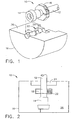
- Figures 1 and 2 illustrate a first die-and-collar assembly 10 that may be used in a swaging machine to swage a work piece, such as tube 12, and a fitting 14.
- the assembly 10 includes a die 16 and a collar 18 that in combination retain the tube 12 and fitting 14 in place during swaging.
- the die includes a fitting recess 20, a collar recess 22, and a tube slot 24 in a die retaining face 26.
- the fitting recess 20 and the tube slot 24 may be sized to accommodate the particular dimensions of the fitting 14 and the tube 12.
- the collar 18 is formed in a configuration that minimizes the opportunity for it to spin within the collar recess 22 when the swaging operation occurs. Although many rotation-prevention configurations are possible, one approach is to form the collar recess 22 in a hex shape. For that shape, the collar 18 could also be hex shape, as shown in Figures 1 and 3. Of course, other types of "anti-rotation" features may form part of the collar 18 and/or the recess 22. One example may be the introduction of a set screw.
- the collar recess 22 has dimensions exceeding the outer dimensions of the collar 18. There may be a slight gap between the sidewalls of the collar recess 22 and the collar 18 when the collar is in place in the collar recess 22. The slight gap permits easy insertion and removal of the collar 18 when applied to the tube 12 as shown in Figure 1. However, that gap is not to be so large as to permit significant fore and aft movement of the collar 18 in the die 16.
- the die 16 and the collar 18 may be formed of any material suitable for swaging work pieces.
- the die 16 and collar 18 may both be made of a similar material, such as steel. Either or both components may alternatively be fabricated of other suitable materials including, but not limited to, Aluminum, stainless steel, Titanium, or Nickel alloys.
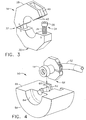
- the collar 18 shown in Figure 3 includes a first clamping section 28 and a second clamping section 30.
- the first clamping section 28 and the second clamping section 30 are connected together by a hinge 32.
- the second clamping section 30 includes in a collar face a collar clasp or collar retainer such as a capture bolt 34.
- the capture bolt 34 includes a bolt body 36 and a bolt head 38.
- the bolt body 36 is designed to fit within a collar slot 40 of the first clamping section 28.
- the collar slot 40 includes retaining prongs 42 against which the bolt head 38 resides when a work piece is disposed between sections 28 and 30.
- the bolt head 38 may be slotted or have similar tightening means such that when tightened onto the prongs 42, the work piece remains fixed in place.
- the hinge 32 provides an easy means for keeping sections 28 and 30 together while making insertion and removal of the work piece simple.
- the collar may alternatively be formed of two separate sections not hingedly connected together. Instead, the two separate sections may be coupled together by alternative collar attachment means, such as a set of threaded bolts and corresponding nuts, among other common attachment options.
- the die-and-collar assembly 10 of Figures 1-3 enables secure placement of a work piece, such as tube 12, into a swaging machine. It eliminates the problems associated with use of the nylon insertion. In particular, it prevents work piece rotation and fore and aft movement of the work piece. It eliminates the need to have an operator manually hold the work piece in place during the swaging operation.
- a "dummy" fitting may be employed prior to insertion of the work piece in the die 16. The dummy fitting, essentially a fitting of the type to be swaged, may be placed in the appropriate position on the tube 12. The collar 18 may then be fixed in place on the tube 12. This procedure may be completed prior to initiating the swaging process.
- the fitting to be swaged and the tube 12 with the collar 18 fixed in place are then inserted into the appropriate recesses in the die face 26.
- the swage machine may then be operated and with the collar 18 in the appropriate position, accurate setback of the fitting 14 on the tube 12 is assured. Sensitivity of the process to roller wear and die tolerance variations is also eliminated.
- FIG. 1-3 The assembly 10 of Figures 1-3 is suitable for retaining a work piece such as tube 12 that has a "long" straight length. However, it may not be suitable for work pieces having "short" straight lengths in relation to the location of the fitting to be swaged.
- Figures 4-6 illustrate a second embodiment of the present invention suitable for work pieces of short straight length.
- a second die-and-collar assembly 50 may be used in a swaging machine to swage a short piece, such as curved tube 52, and a fitting 14.
- the assembly 50 includes a die 54 and a collar 56 that in combination retain the tube 52 and fitting 14 in place during swaging.
- the die includes a fitting recess 58, a collar recess 60, and a chamfered tube slot 62 and an optional expander port 64 in a die retaining face 66.
- the fitting recess 58 may be sized to accommodate the particular dimensions of the fitting 14.
- the chamfered tube slot 62 allows for the insertion of tubes having very short straight sections into the die 54 without impact on the curved portion of the tube 52 that is not held in the die 54.
- the die 54 may also include port 64 to permit insertion of an expander 68 if the tube 52 is to be expanded in the region where the fitting 14 is to be located.
- the collar 56 is formed in a configuration that minimizes the opportunity for it to spin within the collar recess 60 when the swaging operation occurs.
- one approach is to form the collar recess 60 in a hex shape.
- the collar 56 could also be hex shape, as shown in Figures 4 and 6.
- the collar recess 60 has dimensions exceeding the outer dimensions of the collar 56.
- the slight gap permits easy insertion and removal of the collar 56 when applied to the tube 52 as shown in Figure 4.
- that gap is not to be so large as to permit significant fore and aft movement of the collar 56 in the die 54.
- the die 54 and the collar 56 may be formed of any material suitable for swaging work pieces.
- the die 54 and collar 56 may both be made of a similar material, such as steel. Either or both components may alternatively be fabricated of other suitable materials including, but not limited to, Aluminum, stainless steel, Titanium, or Nickel alloys.
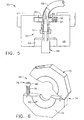
- the collar 56 shown in Figure 6 includes a first clamping section 70 and a second clamping section 72.
- the first clamping section 70 and the second clamping section 72 are connected together by a hinge 74.
- the second clamping section 72 includes in a collar face a collar clasp or collar retainer such as a capture bolt 76.
- the capture bolt 76 includes a bolt body 78 and a bolt head 80.
- the bolt body 78 is designed to fit within a collar slot substantially the same as the arrangement and clamping mechanism of collar 18 of Figure 3.
- the hinge 74 provides an easy means for keeping sections 70 and 72 together while making insertion and removal of the work piece simple.
- the second clamping section 72 includes a chamfer or recess 82 in its vertical face closest to the curve.
- the die-and-collar assembly 50 of Figures 4-6 enables secure placement of a work piece having a short straight length, such as tube 52, into a swaging machine. It eliminates the problems associated with use of the nylon insertion. In particular, it prevents rotation and fore and aft movement of the curved work piece. It eliminates the need to have an operator manually hold the work piece in place during the swaging operation, which may be particularly difficult for curved work pieces.
- a "dummy" fitting may be employed prior to insertion of the work piece in the die 54. The dummy fitting, essentially a fitting of the type to be swaged, may be placed in the appropriate position on the tube 52. The collar 56 may then be fixed in place on the tube 52.
- This procedure may be completed prior to initiating the swaging process.
- the fitting to be swaged and the tube 52 with the collar 56 fixed in place are then inserted into the appropriate recesses in the die face 66.
- the swage machine may then be operated and with the collar 56 in the appropriate position, accurate setback of the fitting 14 on the tube 52 is assured. Sensitivity of the process to roller wear and die tolerance variations is also eliminated.
Landscapes
- Engineering & Computer Science (AREA)
- Mechanical Engineering (AREA)
- Forging (AREA)
- Adornments (AREA)
- Non-Disconnectible Joints And Screw-Threaded Joints (AREA)
Description
- This invention relates generally to swage machines and more particularly to collars and dies used to retain tubes in such machines during the swaging process, see for example US-A-3 726 122.
- Swaging involves the tapering of a rod or tube, such as by forging, hammering, or squeezing. It may also involve the joining together of two components by similar manipulation. For example, a fitting, just as a coupling, may be joined to the exterior of a tube by any of the operations of forging, hammering or squeezing. In general, the fitting is placed on the outside of the rod or tube and then swaged into place, preferably substantially where located. Swaging is a common practice for applying fittings to tubes. A plurality of tubes may be joined together by way of their fitting connections that have been swaged to either or both ends of the tubes.
- Although swaging may be performed manually, swage machines are used to automate and facilitate the process of swaging a fitting to a tube. A wide array of swaging machines is available. Most include means for retaining one or more dies. A die retains the fitting and tube in place during the swaging process. With the fitting and tube in place in the die, pressure is applied to the exterior of the fitting where it is in contact with the exterior of the tube. This is achieved either by rotating the piece, tube, rod, or the like, to be worked or by rotating swaging devices about the piece that remains in a fixed position. The pressure applied to a tube work piece may alternatively be made from the interior of the tube by way of an expander. This is referred to as internal roller swaging.
- In most instances, the fitting is larger than the tube. Given the proximity of the two within a die or set of dies, it is necessary to include means to capture the tube within the die to keep it fixed in place during the swaging process. Such means is a tight-fit annular insert that is placed around the tube and resides in a recess in the die. The insert is generally made of a non-metallic material, such as nylon. The nylon insert wedges the tube in place within the die. For internal roller swaging, a set of opposing die halves is used to position the fitting and tube. Each half includes a half-annular nylon insert. The tube and fitting are placed in one of the halves and then clamped in place when the second die half is mated to the first.
- It has been determined that the nylon insert is inadequate to retain the tube in place during the swaging process. Specifically, because the insert is made of a viscoelastic material, it often fails to provide adequate clamping force during the rigorous swaging process. As a result, the tube rotates and/or moves axially during the process. In addition, the amount of clamping force associated with the die set is dependent on individual die tolerances and die wear when using the nylon inserts. It is therefore often necessary for an operator to hold the tube in place to prevent rotation and axial movement. This limits the efficiency of the automated swaging process, minimizes the operator's ability to perform other tasks, and increases the yield of detective parts. Therefore, what is needed is a die and die-to-tube interface arrangement that retain the tube and fitting in place with certainty during swaging.
- The above-mentioned need is met by the present invention, which provides a wage die and collar assembly for retaining a work piece in a swage machine. The assembly includes a collar releasably placcable on the work piece and including a first clamping section and a second clamping section connected together and a die in sertable into the swage machine. The die includes a work piece slot and a collar recess in a die face of the die. The collar recess is configured to retain the collar that in turn is coupled about the work piece.
- For curved work pieces, the collar may include in one of its faces a chamfered section to accommodate the curved portion of the work piece. The collar recess and the collar may be of hexagonal shape. When a fitting is to be swaged to the work piece, a fitting recess is formed in the die face. In addition, a dummy fitting may be used to fix the position of the collar on the work piece before swaging a final fitting.
- The present invention and its advantages over the prior art will become apparent upon reading the following detailed description and the appended claims with reference to the accompanying drawings.
- The subject matter that is regarded as the invention is particularly pointed out and distinctly claimed in the concluding part of the specification. The invention, however, may be best understood by reference to the following description taken in conjunction with the accompanying drawing figures in which:
- Figure 1 is a perspective view of a first embodiment of the die and collar assembly of the present invention, showing one of a mirror-image pair of dies and a tube with fitting and collar thereon.
- Figure 2 is a top view of the die section of Figure 1 with the tube, fitting and collar in place.
- Figure 3 is a perspective view of the collar of the first embodiment of the present invention shown partially open.
- Figure 4 is a perspective view of a second embodiment of the die and collar assembly of the present invention, showing one of a mirror-image pair of dies and a tube with fitting and collar thereon.
- Figure 5 is a top view of the die section of Figure 4 with the tube, fitting and collar in place.
- Figure 6 is a perspective view of the collar of the second embodiment of the present invention shown partially open and with chamfer to accept short-straight-length tube for swaging.
- Referring to the drawings wherein identical reference numerals denote the same elements, Figures 1 and 2 illustrate a first die-and-
collar assembly 10 that may be used in a swaging machine to swage a work piece, such astube 12, and afitting 14. Theassembly 10 includes adie 16 and acollar 18 that in combination retain thetube 12 and fitting 14 in place during swaging. The die includes afitting recess 20, a collar recess 22, and atube slot 24 in a dieretaining face 26. - The fitting recess 20 and the
tube slot 24 may be sized to accommodate the particular dimensions of thefitting 14 and thetube 12. Thecollar 18 is formed in a configuration that minimizes the opportunity for it to spin within thecollar recess 22 when the swaging operation occurs. Although many rotation-prevention configurations are possible, one approach is to form the collar recess 22 in a hex shape. For that shape, thecollar 18 could also be hex shape, as shown in Figures 1 and 3. Of course, other types of "anti-rotation" features may form part of thecollar 18 and/or therecess 22. One example may be the introduction of a set screw. - With continuing reference to Figures 1-3, the
collar recess 22 has dimensions exceeding the outer dimensions of thecollar 18. There may be a slight gap between the sidewalls of the collar recess 22 and thecollar 18 when the collar is in place in the collar recess 22. The slight gap permits easy insertion and removal of thecollar 18 when applied to thetube 12 as shown in Figure 1. However, that gap is not to be so large as to permit significant fore and aft movement of thecollar 18 in the die 16. - The die 16 and the
collar 18 may be formed of any material suitable for swaging work pieces. Thedie 16 andcollar 18 may both be made of a similar material, such as steel. Either or both components may alternatively be fabricated of other suitable materials including, but not limited to, Aluminum, stainless steel, Titanium, or Nickel alloys. Thecollar 18 shown in Figure 3 includes afirst clamping section 28 and asecond clamping section 30. Thefirst clamping section 28 and thesecond clamping section 30 are connected together by ahinge 32. Thesecond clamping section 30 includes in a collar face a collar clasp or collar retainer such as acapture bolt 34. Thecapture bolt 34 includes abolt body 36 and abolt head 38. Thebolt body 36 is designed to fit within acollar slot 40 of thefirst clamping section 28. Thecollar slot 40 includes retainingprongs 42 against which thebolt head 38 resides when a work piece is disposed betweensections bolt head 38 may be slotted or have similar tightening means such that when tightened onto theprongs 42, the work piece remains fixed in place. Thehinge 32 provides an easy means for keepingsections - The die-and-
collar assembly 10 of Figures 1-3 enables secure placement of a work piece, such astube 12, into a swaging machine. It eliminates the problems associated with use of the nylon insertion. In particular, it prevents work piece rotation and fore and aft movement of the work piece. It eliminates the need to have an operator manually hold the work piece in place during the swaging operation. In addition, a "dummy" fitting may be employed prior to insertion of the work piece in thedie 16. The dummy fitting, essentially a fitting of the type to be swaged, may be placed in the appropriate position on thetube 12. Thecollar 18 may then be fixed in place on thetube 12. This procedure may be completed prior to initiating the swaging process. The fitting to be swaged and thetube 12 with thecollar 18 fixed in place are then inserted into the appropriate recesses in thedie face 26. The swage machine may then be operated and with thecollar 18 in the appropriate position, accurate setback of the fitting 14 on thetube 12 is assured. Sensitivity of the process to roller wear and die tolerance variations is also eliminated. - The
assembly 10 of Figures 1-3 is suitable for retaining a work piece such astube 12 that has a "long" straight length. However, it may not be suitable for work pieces having "short" straight lengths in relation to the location of the fitting to be swaged. Figures 4-6 illustrate a second embodiment of the present invention suitable for work pieces of short straight length. A second die-and-collar assembly 50 may be used in a swaging machine to swage a short piece, such ascurved tube 52, and a fitting 14. Theassembly 50 includes adie 54 and acollar 56 that in combination retain thetube 52 and fitting 14 in place during swaging. The die includes a fitting recess 58, acollar recess 60, and achamfered tube slot 62 and anoptional expander port 64 in adie retaining face 66. - The fitting recess 58 may be sized to accommodate the particular dimensions of the fitting 14. The chamfered
tube slot 62 allows for the insertion of tubes having very short straight sections into thedie 54 without impact on the curved portion of thetube 52 that is not held in thedie 54. The die 54 may also includeport 64 to permit insertion of anexpander 68 if thetube 52 is to be expanded in the region where the fitting 14 is to be located. - The
collar 56 is formed in a configuration that minimizes the opportunity for it to spin within thecollar recess 60 when the swaging operation occurs. Although many rotation-prevention configurations are possible, one approach is to form thecollar recess 60 in a hex shape. For that shape, thecollar 56 could also be hex shape, as shown in Figures 4 and 6. Thecollar recess 60 has dimensions exceeding the outer dimensions of thecollar 56. There may be a slight gap between the sidewalls of thecollar recess 60 and thecollar 56 when the collar is in place in thecollar recess 60. The slight gap permits easy insertion and removal of thecollar 56 when applied to thetube 52 as shown in Figure 4. However, that gap is not to be so large as to permit significant fore and aft movement of thecollar 56 in thedie 54. - The
die 54 and thecollar 56 may be formed of any material suitable for swaging work pieces. Thedie 54 andcollar 56 may both be made of a similar material, such as steel. Either or both components may alternatively be fabricated of other suitable materials including, but not limited to, Aluminum, stainless steel, Titanium, or Nickel alloys. Thecollar 56 shown in Figure 6 includes afirst clamping section 70 and asecond clamping section 72. Thefirst clamping section 70 and thesecond clamping section 72 are connected together by ahinge 74. Thesecond clamping section 72 includes in a collar face a collar clasp or collar retainer such as acapture bolt 76. Thecapture bolt 76 includes abolt body 78 and abolt head 80. Thebolt body 78 is designed to fit within a collar slot substantially the same as the arrangement and clamping mechanism ofcollar 18 of Figure 3. Thehinge 74 provides an easy means for keepingsections tube 52, thesecond clamping section 72 includes a chamfer orrecess 82 in its vertical face closest to the curve. - The die-and-
collar assembly 50 of Figures 4-6 enables secure placement of a work piece having a short straight length, such astube 52, into a swaging machine. It eliminates the problems associated with use of the nylon insertion. In particular, it prevents rotation and fore and aft movement of the curved work piece. It eliminates the need to have an operator manually hold the work piece in place during the swaging operation, which may be particularly difficult for curved work pieces. As withassembly 10, a "dummy" fitting may be employed prior to insertion of the work piece in thedie 54. The dummy fitting, essentially a fitting of the type to be swaged, may be placed in the appropriate position on thetube 52. Thecollar 56 may then be fixed in place on thetube 52. This procedure may be completed prior to initiating the swaging process. The fitting to be swaged and thetube 52 with thecollar 56 fixed in place are then inserted into the appropriate recesses in thedie face 66. The swage machine may then be operated and with thecollar 56 in the appropriate position, accurate setback of the fitting 14 on thetube 52 is assured. Sensitivity of the process to roller wear and die tolerance variations is also eliminated.
Claims (9)
- A swage die and collar assembly (10, 50) for retaining a work piece in a swage machine, the assembly (10, 50) comprising:a collar (18, 56) releasably placeable on the work piece and induding a first clamping section (28, 70) and a second damping section (30, 72) connected together,a die (16, 54) insertable into the swage machine, said die (16, 54) including a work piece slot (24, 62) and a collar recess (22, 60) in a die face (26, 66) thereof, wherein said collar recess (22, 60) is configured to hold said collar (18, 56) therein.
- The assembly (10, 50) of claim 1 wherein said second damping section (30, 72) indudes a clamping bolt (34, 76) for releasably damping said collar (18, 56) about the work piece, wherein said clamping bolt (34, 76) joins said first clamping section (28, 70) and said second clamping section (30, 72).
- The assembly (50) of claim 1 wherein the work piece is a curved work piece and said second clamping section (72) of said collar (56) indudes a chamfered facing (66) and said die (54) includes a chamfered work piece port (62).
- The assembly (10, 50) of any preceding claim further comprising an anti-rotation feature such that said collar (18, 56) does not rotate within said collar recess (22, 60).
- A method for swaging a work piece in a swage machine, the method comprising the steps of:applying a collar (18, 56) about the work piece at a selectable position;tightening said collar (18, 56) about the work piece;inserting said collar (18, 56) and the work piece in a collar recess (22, 60) and a work piece slot (24, 62), respectively, of a die (16, 54); andinserting said die (16, 54) with said collar (18, 56) and the work piece into the swage machine.
- The method of claim 5 further comprising before the step of applying said collar (18, 56) about the work piece the step of placing a dummy fitting on the work piece in a selectable position and after applying and tightening said collar (18, 56), removing said dummy fitting and applying to the work piece a fitting to be swaged to the work piece.
- The method of claim 5 or 6 further comprising the step of forming a fitting recess (20, 58) in said die face (26, 66) for receiving therein a fitting to be swaged to the work piece.
- The method of claim 5 or 6 wherein the work piece is a tube, further comprising the step of forming an expander port (64) in said die face (66) of said die (54).
- The method of any one of claims 5 to 8 wherein said collar (18, 56) includes a first clamping section (28, 70) and a second clamping section (30, 72) hingedly connected together.
Applications Claiming Priority (3)
| Application Number | Priority Date | Filing Date | Title |
|---|---|---|---|
| US09/668,909 US6412160B1 (en) | 2000-09-22 | 2000-09-22 | Swaged tube fitting collar and die |
| US668909 | 2000-09-22 | ||
| PCT/US2001/028819 WO2002024373A2 (en) | 2000-09-22 | 2001-09-14 | Swaged tube fitting collar and die |
Publications (2)
| Publication Number | Publication Date |
|---|---|
| EP1322437A2 EP1322437A2 (en) | 2003-07-02 |
| EP1322437B1 true EP1322437B1 (en) | 2006-06-14 |
Family
ID=24684246
Family Applications (1)
| Application Number | Title | Priority Date | Filing Date |
|---|---|---|---|
| EP01971016A Expired - Lifetime EP1322437B1 (en) | 2000-09-22 | 2001-09-14 | Swaged tube fitting collar and die |
Country Status (12)
| Country | Link |
|---|---|
| US (1) | US6412160B1 (en) |
| EP (1) | EP1322437B1 (en) |
| JP (1) | JP5072165B2 (en) |
| CN (1) | CN1236876C (en) |
| AU (1) | AU2001290953A1 (en) |
| BR (1) | BR0114064A (en) |
| CA (1) | CA2421555C (en) |
| DE (1) | DE60120727T2 (en) |
| MX (1) | MXPA03002379A (en) |
| MY (1) | MY126114A (en) |
| RU (1) | RU2272691C2 (en) |
| WO (1) | WO2002024373A2 (en) |
Cited By (1)
| Publication number | Priority date | Publication date | Assignee | Title |
|---|---|---|---|---|
| FR3050949A1 (en) * | 2016-05-06 | 2017-11-10 | Soc D'assemblage Et Brasage | PRE-ASSEMBLY DEVICE FOR CUTTING RING FITTING CRIMPING MACHINE, AND CRIMPING MACHINE COMPRISING SAME |
Families Citing this family (7)
| Publication number | Priority date | Publication date | Assignee | Title |
|---|---|---|---|---|
| US6659976B2 (en) * | 2001-04-16 | 2003-12-09 | Zevek, Inc. | Feeding set adaptor |
| DE50206802D1 (en) * | 2002-02-21 | 2006-06-22 | Ford Global Tech Llc | Heated cup system |
| US6802366B1 (en) * | 2002-10-31 | 2004-10-12 | Advanced Energy Industries, Inc. | Swage method for cooling pipes |
| WO2006015444A2 (en) * | 2004-08-12 | 2006-02-16 | Brian Investments Pty Ltd | A screw threaded member |
| US8590129B2 (en) * | 2011-06-16 | 2013-11-26 | Noel E. Garces | Temporary beveled clamping surface casing alignment tool (CAT) |
| CN103934400A (en) * | 2014-03-17 | 2014-07-23 | 天津机辆轨道交通装备有限责任公司 | Pull rod forging tool of expanding device |
| US10955839B1 (en) * | 2020-05-28 | 2021-03-23 | Trinity Bay Equipment Holdings, LLC | Remotely operated pipe fitting swaging systems and methods |
Family Cites Families (25)
| Publication number | Priority date | Publication date | Assignee | Title |
|---|---|---|---|---|
| US2381747A (en) * | 1942-11-02 | 1945-08-07 | Chicago Forging & Manufactuing | Tool for forming joints |
| US2972186A (en) * | 1955-11-14 | 1961-02-21 | Chicago Forging & Mfg Co | Mandrel swage |
| US3115797A (en) * | 1955-11-14 | 1963-12-31 | Earl E Howe | Mandrel swage |
| US3019520A (en) * | 1961-01-23 | 1962-02-06 | Tex Tube Inc | Pipe crimping apparatus |
| US3230754A (en) * | 1961-12-28 | 1966-01-25 | Alfred C Arbogast | Means for forming tube fittings |
| US3244441A (en) * | 1961-12-28 | 1966-04-05 | Mueller Co | Crimped tube joint |
| US3252192A (en) * | 1964-04-01 | 1966-05-24 | Joseph B Smith | Clamp ring for pipe and the like |
| US3503244A (en) * | 1967-05-29 | 1970-03-31 | Joslin Alvin E | Pipe holding mechanism |
| US3726122A (en) * | 1971-03-10 | 1973-04-10 | Mc Donnell Douglas Corp | Swaging tool |
| US3803897A (en) * | 1971-03-11 | 1974-04-16 | Universal Refrigeration Inc | Compression staking apparatus |
| US3724053A (en) * | 1971-09-28 | 1973-04-03 | Lockheed Aircraft Corp | Apparatus for performing axially-and-radially located operations on tubular construction |
| US3838591A (en) * | 1972-08-30 | 1974-10-01 | B Ross | Automatic pipe swaging apparatus |
| US3959998A (en) * | 1972-08-30 | 1976-06-01 | Ross Bernard D | Pipe swaging apparatus |
| US3848451A (en) * | 1972-11-24 | 1974-11-19 | Deutsch Co Metal Components | Swaging tool |
| US3956815A (en) * | 1975-05-06 | 1976-05-18 | Amp Incorporated | Explosively propelled equal mass tubular member swaging tool |
| US4418458A (en) * | 1978-08-09 | 1983-12-06 | Hunter John J | Apparatus for making pipe coupling joint |
| SU837723A1 (en) * | 1980-01-18 | 1981-06-15 | Государственный Проектно-Конструкторскийи Технологический Институт Подъемно-Транспортного Машиностроения | Apparatus for assembling hoses |
| US4362042A (en) * | 1980-10-01 | 1982-12-07 | The Lamson & Sessions Co. | Method of forming a fastener |
| US4773249A (en) * | 1986-11-26 | 1988-09-27 | Dana Corporation | Hose fitting crimper |
| US5040396A (en) * | 1990-01-19 | 1991-08-20 | Sierracin Corporation | Portable internal roller swager |
| US5056208A (en) * | 1990-03-19 | 1991-10-15 | Vsi Corporation | Method for providing captive panel fastener assembly |
| US5454152A (en) * | 1993-09-16 | 1995-10-03 | Sierracin Corporation | Roller swaging tool |
| US5657656A (en) * | 1995-12-29 | 1997-08-19 | Aeroquip Corporation | Automatic positioning system for a hose assembly and method therefor |
| US5776519A (en) * | 1997-06-06 | 1998-07-07 | Graham Engineering Corporation | Parison extrusion head with quick change die ring clamp assembly |
| US6199254B1 (en) * | 1999-11-05 | 2001-03-13 | Mechl Llc | Swaging tool with multiple pushers |
-
2000
- 2000-09-22 US US09/668,909 patent/US6412160B1/en not_active Expired - Lifetime
-
2001
- 2001-09-14 DE DE60120727T patent/DE60120727T2/en not_active Expired - Lifetime
- 2001-09-14 EP EP01971016A patent/EP1322437B1/en not_active Expired - Lifetime
- 2001-09-14 RU RU2003111465/02A patent/RU2272691C2/en not_active IP Right Cessation
- 2001-09-14 WO PCT/US2001/028819 patent/WO2002024373A2/en not_active Ceased
- 2001-09-14 CA CA002421555A patent/CA2421555C/en not_active Expired - Fee Related
- 2001-09-14 AU AU2001290953A patent/AU2001290953A1/en not_active Abandoned
- 2001-09-14 MX MXPA03002379A patent/MXPA03002379A/en active IP Right Grant
- 2001-09-14 JP JP2002528431A patent/JP5072165B2/en not_active Expired - Fee Related
- 2001-09-14 BR BR0114064-7A patent/BR0114064A/en not_active IP Right Cessation
- 2001-09-14 CN CNB018161650A patent/CN1236876C/en not_active Expired - Fee Related
- 2001-09-21 MY MYPI20014424A patent/MY126114A/en unknown
Cited By (1)
| Publication number | Priority date | Publication date | Assignee | Title |
|---|---|---|---|---|
| FR3050949A1 (en) * | 2016-05-06 | 2017-11-10 | Soc D'assemblage Et Brasage | PRE-ASSEMBLY DEVICE FOR CUTTING RING FITTING CRIMPING MACHINE, AND CRIMPING MACHINE COMPRISING SAME |
Also Published As
| Publication number | Publication date |
|---|---|
| MXPA03002379A (en) | 2003-06-30 |
| EP1322437A2 (en) | 2003-07-02 |
| BR0114064A (en) | 2003-10-14 |
| JP5072165B2 (en) | 2012-11-14 |
| AU2001290953A1 (en) | 2002-04-02 |
| JP2004508938A (en) | 2004-03-25 |
| WO2002024373A2 (en) | 2002-03-28 |
| CN1236876C (en) | 2006-01-18 |
| RU2272691C2 (en) | 2006-03-27 |
| CN1466500A (en) | 2004-01-07 |
| CA2421555A1 (en) | 2002-03-28 |
| DE60120727D1 (en) | 2006-07-27 |
| US6412160B1 (en) | 2002-07-02 |
| WO2002024373A3 (en) | 2002-06-20 |
| CA2421555C (en) | 2009-04-14 |
| DE60120727T2 (en) | 2007-07-12 |
| MY126114A (en) | 2006-09-29 |
Similar Documents
| Publication | Publication Date | Title |
|---|---|---|
| US6082784A (en) | Connection structure and process for connecting eye-joints and slender metal pipes | |
| AU2004202418B2 (en) | Deformed Reinforcing Bar Splice and Method | |
| US4813834A (en) | Fit-up fastener with flexible tab-like retaining structure and method of making same | |
| JP3488201B2 (en) | Bolt press-fitting equipment | |
| US4969785A (en) | Fastener mandrel and method | |
| RU2429933C1 (en) | Manufacturing method and device for tubular parts from hollow unit pre-equipped with hole | |
| US6412160B1 (en) | Swaged tube fitting collar and die | |
| US6193195B1 (en) | Clamp for metal tubing | |
| JPS63252632A (en) | Swap forging method and forging equipment for long stands from metal bar materials | |
| US6108895A (en) | Method of axially swaging a male end fitting assembly | |
| EP1359330A1 (en) | Blind rivet and fastening method | |
| WO1986006448A1 (en) | Variable clamp fastener and method of using same for securing workpieces together | |
| US5186570A (en) | Fastening device for the releasable fastening of a strut to a column, a column for holding struts, and strut for fastening to a column | |
| EP1567799B1 (en) | Hydraulic hose fitting | |
| EP0663535A1 (en) | Component mounting assembly and method | |
| US20230120330A1 (en) | Apparatus and method for disassembling a pipe joint | |
| DE19923164A1 (en) | Chuck for clamping tools through shrink fit | |
| US6019559A (en) | Fastener having spiral shaped collar portion | |
| JPH06198358A (en) | Method and device for fixing tubular reinforcing insert into tubular metal structure | |
| JPH07227698A (en) | Welding jig for pipe connection | |
| US4829654A (en) | Method of manufacturing a pressurized fluid coupling | |
| JPH11197786A (en) | Manufacturing method of collar or collar nut | |
| GB2356677A (en) | Blind fastener with separately-formed swaging collar | |
| EP0052480A1 (en) | Lockbolts and methods of and means for setting them | |
| JPS5913146A (en) | Connection between torque tube and anchor arm in torsion spring apparatus |
Legal Events
| Date | Code | Title | Description |
|---|---|---|---|
| PUAI | Public reference made under article 153(3) epc to a published international application that has entered the european phase |
Free format text: ORIGINAL CODE: 0009012 |
|
| 17P | Request for examination filed |
Effective date: 20030422 |
|
| AK | Designated contracting states |
Designated state(s): AT BE CH CY DE DK ES FI FR GB GR IE IT LI LU MC NL PT SE TR |
|
| AX | Request for extension of the european patent |
Extension state: AL LT LV MK RO SI |
|
| 17Q | First examination report despatched |
Effective date: 20040415 |
|
| RBV | Designated contracting states (corrected) |
Designated state(s): DE FR GB IT SE |
|
| GRAP | Despatch of communication of intention to grant a patent |
Free format text: ORIGINAL CODE: EPIDOSNIGR1 |
|
| GRAS | Grant fee paid |
Free format text: ORIGINAL CODE: EPIDOSNIGR3 |
|
| GRAA | (expected) grant |
Free format text: ORIGINAL CODE: 0009210 |
|
| AK | Designated contracting states |
Kind code of ref document: B1 Designated state(s): DE FR GB IT SE |
|
| REG | Reference to a national code |
Ref country code: GB Ref legal event code: FG4D |
|
| REF | Corresponds to: |
Ref document number: 60120727 Country of ref document: DE Date of ref document: 20060727 Kind code of ref document: P |
|
| REG | Reference to a national code |
Ref country code: SE Ref legal event code: TRGR |
|
| ET | Fr: translation filed | ||
| PLBE | No opposition filed within time limit |
Free format text: ORIGINAL CODE: 0009261 |
|
| STAA | Information on the status of an ep patent application or granted ep patent |
Free format text: STATUS: NO OPPOSITION FILED WITHIN TIME LIMIT |
|
| 26N | No opposition filed |
Effective date: 20070315 |
|
| PGFP | Annual fee paid to national office [announced via postgrant information from national office to epo] |
Ref country code: SE Payment date: 20060927 Year of fee payment: 6 |
|
| PG25 | Lapsed in a contracting state [announced via postgrant information from national office to epo] |
Ref country code: SE Free format text: LAPSE BECAUSE OF NON-PAYMENT OF DUE FEES Effective date: 20070915 |
|
| EUG | Se: european patent has lapsed | ||
| REG | Reference to a national code |
Ref country code: FR Ref legal event code: PLFP Year of fee payment: 15 |
|
| PGFP | Annual fee paid to national office [announced via postgrant information from national office to epo] |
Ref country code: GB Payment date: 20150928 Year of fee payment: 15 |
|
| PGFP | Annual fee paid to national office [announced via postgrant information from national office to epo] |
Ref country code: FR Payment date: 20150917 Year of fee payment: 15 |
|
| PGFP | Annual fee paid to national office [announced via postgrant information from national office to epo] |
Ref country code: IT Payment date: 20150923 Year of fee payment: 15 |
|
| PGFP | Annual fee paid to national office [announced via postgrant information from national office to epo] |
Ref country code: DE Payment date: 20150929 Year of fee payment: 15 |
|
| REG | Reference to a national code |
Ref country code: DE Ref legal event code: R119 Ref document number: 60120727 Country of ref document: DE |
|
| GBPC | Gb: european patent ceased through non-payment of renewal fee |
Effective date: 20160914 |
|
| REG | Reference to a national code |
Ref country code: FR Ref legal event code: ST Effective date: 20170531 |
|
| PG25 | Lapsed in a contracting state [announced via postgrant information from national office to epo] |
Ref country code: DE Free format text: LAPSE BECAUSE OF NON-PAYMENT OF DUE FEES Effective date: 20170401 Ref country code: GB Free format text: LAPSE BECAUSE OF NON-PAYMENT OF DUE FEES Effective date: 20160914 Ref country code: FR Free format text: LAPSE BECAUSE OF NON-PAYMENT OF DUE FEES Effective date: 20160930 |
|
| PG25 | Lapsed in a contracting state [announced via postgrant information from national office to epo] |
Ref country code: IT Free format text: LAPSE BECAUSE OF NON-PAYMENT OF DUE FEES Effective date: 20160914 |