EP1322436B1 - Cold forming of splined transmission hubs - Google Patents
Cold forming of splined transmission hubs Download PDFInfo
- Publication number
- EP1322436B1 EP1322436B1 EP20010975903 EP01975903A EP1322436B1 EP 1322436 B1 EP1322436 B1 EP 1322436B1 EP 20010975903 EP20010975903 EP 20010975903 EP 01975903 A EP01975903 A EP 01975903A EP 1322436 B1 EP1322436 B1 EP 1322436B1
- Authority
- EP
- European Patent Office
- Prior art keywords
- blank
- forming
- support member
- tool insert
- forming roller
- Prior art date
- Legal status (The legal status is an assumption and is not a legal conclusion. Google has not performed a legal analysis and makes no representation as to the accuracy of the status listed.)
- Expired - Lifetime
Links
- 238000000034 method Methods 0.000 claims abstract description 18
- 230000005540 biological transmission Effects 0.000 claims abstract description 8
- 238000005728 strengthening Methods 0.000 claims description 4
- 230000000063 preceeding effect Effects 0.000 claims 1
- 229910000831 Steel Inorganic materials 0.000 description 4
- 239000000463 material Substances 0.000 description 4
- 239000010959 steel Substances 0.000 description 4
- 238000004519 manufacturing process Methods 0.000 description 3
- 239000002184 metal Substances 0.000 description 2
- 238000005520 cutting process Methods 0.000 description 1
- 238000003780 insertion Methods 0.000 description 1
- 230000037431 insertion Effects 0.000 description 1
- 239000000314 lubricant Substances 0.000 description 1
- 238000003754 machining Methods 0.000 description 1
- 238000012986 modification Methods 0.000 description 1
- 230000004048 modification Effects 0.000 description 1
- 239000007858 starting material Substances 0.000 description 1
Images


Classifications
-
- B—PERFORMING OPERATIONS; TRANSPORTING
- B21—MECHANICAL METAL-WORKING WITHOUT ESSENTIALLY REMOVING MATERIAL; PUNCHING METAL
- B21D—WORKING OR PROCESSING OF SHEET METAL OR METAL TUBES, RODS OR PROFILES WITHOUT ESSENTIALLY REMOVING MATERIAL; PUNCHING METAL
- B21D53/00—Making other particular articles
- B21D53/26—Making other particular articles wheels or the like
- B21D53/28—Making other particular articles wheels or the like gear wheels
-
- F—MECHANICAL ENGINEERING; LIGHTING; HEATING; WEAPONS; BLASTING
- F16—ENGINEERING ELEMENTS AND UNITS; GENERAL MEASURES FOR PRODUCING AND MAINTAINING EFFECTIVE FUNCTIONING OF MACHINES OR INSTALLATIONS; THERMAL INSULATION IN GENERAL
- F16D—COUPLINGS FOR TRANSMITTING ROTATION; CLUTCHES; BRAKES
- F16D13/00—Friction clutches
- F16D13/58—Details
- F16D13/60—Clutching elements
- F16D13/64—Clutch-plates; Clutch-lamellae
- F16D13/68—Attachments of plates or lamellae to their supports
- F16D13/683—Attachments of plates or lamellae to their supports for clutches with multiple lamellae
-
- F—MECHANICAL ENGINEERING; LIGHTING; HEATING; WEAPONS; BLASTING
- F16—ENGINEERING ELEMENTS AND UNITS; GENERAL MEASURES FOR PRODUCING AND MAINTAINING EFFECTIVE FUNCTIONING OF MACHINES OR INSTALLATIONS; THERMAL INSULATION IN GENERAL
- F16D—COUPLINGS FOR TRANSMITTING ROTATION; CLUTCHES; BRAKES
- F16D2250/00—Manufacturing; Assembly
- F16D2250/0023—Shaping by pressure
-
- Y—GENERAL TAGGING OF NEW TECHNOLOGICAL DEVELOPMENTS; GENERAL TAGGING OF CROSS-SECTIONAL TECHNOLOGIES SPANNING OVER SEVERAL SECTIONS OF THE IPC; TECHNICAL SUBJECTS COVERED BY FORMER USPC CROSS-REFERENCE ART COLLECTIONS [XRACs] AND DIGESTS
- Y10—TECHNICAL SUBJECTS COVERED BY FORMER USPC
- Y10T—TECHNICAL SUBJECTS COVERED BY FORMER US CLASSIFICATION
- Y10T29/00—Metal working
- Y10T29/49—Method of mechanical manufacture
- Y10T29/49481—Wheel making
- Y10T29/49492—Land wheel
- Y10T29/49533—Hub making
Definitions
- the invention relates to hubs for automotive transmissions. More particularly, this invention relates to a one-step production method for cold forming a hub of an automotive transmission.
- Flow forming of transmission components is a common manufacturing process.
- a tubular shell is provided from a stamped disc, and internal drive spline teeth are roll formed while maintaining a smooth and constant outer diameter.
- axial roll forming a cup-shaped blank is mounted on a shaped mandrel, and a roll formed tool moves axially to press the metal to the tooth shape on the mandrel, essentially one tooth at a time. The mandrel is rotated to present the unworked surface to the roll form to allow the entire inner surface to be splined.
- United States Patent 5,515,955 discloses such a cold forming process to generate spline teeth in a torque converter.
- United States Patent 5,384,949 discloses a multi-step cold forming process for forming a clutch housing with an internal radial spline, a torque transmitting tube portion and an axially extending drive portion.
- the existing methods are limited to housings with internal splines, or housings with external splines that must be subsequently machined or broached to achieve acceptable tolerances.
- An oil reservoir or dam typically present to supply lubricant between the spline teeth and contacting clutch plates, is typically machined into housings in a separate and subsequent metal removal step.
- the invention describes a method according to claim 1 for cold forming a transmission hub from a blank having an outer surface and an inner surface using a tool insert support member having a spline tooth portion and a reservoir portion including a forming roller.
- the method includes the steps of positioning the blank axially with the spline tooth portion of the tool insert support member, engaging the spline tooth portion with the outer surface of the blank, exerting a radial pressure on the blank forcing the blank into engagement with the spline tooth portion, creating a set of teeth on the outer surface of the blank; and rotating the blank relative to the forming roller to form an oil reservoir on the inner surface of the blank.
- the invention describes further an apparatus for cold forming a transmission hub according to claim 9.
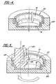
- a cup-shaped blank 10 is provided having an internal step, defined in part by gentle radii R, R 1 and R 2 .
- the blank 10 has two diameters defined by an outer diameter D o and an inner diameter D i .
- the blank 10 includes an outer surface 12 and an inner surface 14.
- a bottom surface of blank 10 is indicated at 16.
- the blank 10 is a circular disk that is mounted onto a mandrel or die and is drawn into the shape by well-known techniques. As shown in Figure 2, a pair of circular holes 20 are drilled or otherwise punched out of a bottom surface 16 of the blank 10, the purpose of which will be explained later.
- the blank 10 is preferably formed from steel, which is capable of being cold formed.
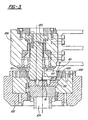
- the blank 10 is positioned in a tool insert support member 100, as shown in Figures 3, 4, and 5.
- the tool insert support member 100 is inserted into an opening (not shown) of a lower tool member 102.
- the opening of the lower tool member 102 may be adjusted to receive tool insert support members 100 of different sizes.
- a shaft 104 raises and lowers the lower tool member 102 to accommodate different sized tool insert support members 100.
- the same lower tool member 102 may be used for cold forming blanks 10 of various shapes.
- the blank 10 is secured to the tool insert support member 100 by pins (not shown) that are inserted into the lower tool member 102 through the circular holes 20.
- the tool insert support member 100 has a spline tooth profile 110 permanently machined into its interior.
- a preformed blank is created by moving a forming roller 120 into the interior volume of the blank 10 and abutting same on the interior surface 14.
- the forming roller 120 is a component of an upper tool member 124, and is mounted in an opening (not shown) therein.
- the opening of the upper tool member 124 is sized to accommodate rollers of various sizes.
- the upper tool member 124 and the lower tool member 102 are two pieces. However, a one-piece tooling member may also be used.
- the outer diameter of the forming roller 120 is typically 40-60% of the outer diameter of the blank 10. However, smaller roller diameters can be used to maximize the amount of cold forming per revolution.
- the forming roller 120 first moves in a vertically downward direction, until it is positioned just above the bottom surface 16 of the blank 10. The forming roller 120 does not make contact with the bottom surface 16 because surface removal of material undesirable.
- the contoured shape of the forming roller 120 includes a protrusion 125 and recess 126.
- the protrusion 125 is pressed against the inner surface 14 of the blank 10 to cold form an oil dam or inner oil reservoir 112 on the inner surface 14 of the blank while the spline teeth 111 are formed on the outer surface 12 of the blank 10.
- the recess 126 allows material to flow past the protrusion 125 to limit the width of the oil reservoir 112 by creating a wall 113.
- An edge lip 127 is also provided on the forming roller 120. The edge lip 127 forms a strengthening shoulder region 140 on the blank 10.
- the tool insert 100 is rotated by an electric motor drive or other suitable device. Rotational speeds are normally above 600 rpm, although slower speeds can also be used.
- the forming roller 120 is free running upon contacting the blank 10 as pressure is applied. In an alternative embodiment, the forming roller 120 may also rotate. Regardless, once the forming roller 120 contacts the rotating blank when a force 121 is applied thereto laterally, the forming roller 120 forces the blank 10 into shape.
- the spline teeth 111 are formed on the outer surface 12 of the blank 10 and the oil reservoir 112 is cold formed on the inner surface 14 of the blank 10. Because the oil reservoir 112 and the spline teeth 111 are created at the same time, no further machining steps are required. In addition, a strengthening shoulder 140 that interconnects the spline teeth 111 is formed along the outer periphery of the blank 10.
Landscapes
- Engineering & Computer Science (AREA)
- Mechanical Engineering (AREA)
- General Engineering & Computer Science (AREA)
- Forging (AREA)
- Mechanical Operated Clutches (AREA)
- Rotational Drive Of Disk (AREA)
- Manufacture Of Motors, Generators (AREA)
- General Details Of Gearings (AREA)
- Shaping Metal By Deep-Drawing, Or The Like (AREA)
Abstract
Description
Claims (9)
- A method for cold forming a transmission hub from a cup-shaped blank (10) having an outer surface and an inner surface, the method comprising the steps of:positioning the blank (10) axially within of a tool insert support member (100) having a spline tooth portion (110);exerting a radial pressure on the blank (10) forcing the blank into engagement with the spline tooth portion (110) thereby forming a set of teeth (111) on the outer surface of the blank; andforming an oil reservoir (112) in the inner surface of the blank.
- A method as claimed in claim 1 wherein said exerting step and said forming step occur simultaneously.
- A method as claimed in claim 2 wherein said exerting step and said forming step includes rotating a forming roller (120) relative to said blank (10) to form said oil reservoir and exert said radial pressure.
- A method as set forth in claim 3 wherein said method includes a step of forming a wall defining a portion of said reservoir (112).
- A method as set forth in claim 4 including a step of forming a strengthening lip (140) around a periphery of the blank interconnecting said set of teeth.
- A method as set forth in claim 4 wherein said wall and strengthening lip are formed simultaneously with said set of teeth and said reservoir.
- A method as set forth in claim 6 wherein said tool insert support member is rotated in excess of 600 RPM.
- A method as set forth in claim 3 wherein said forming roller has an outer diameter and said blank has an outer diameter, said outer diameter of the forming roller is 40-60% of the outer diameter of the blank.
- An apparatus for cold forming a transmission hub as set forth in any preceeding claim, comprisinga tool insert support member (100) having a spline tooth portion (110);a freely rotating forming roller (120); anda drive for rotating said tool insert support member (100) relative to said forming roller (120) and for moving said forming roller radially and axially relative to said tool insert support member.
Applications Claiming Priority (3)
| Application Number | Priority Date | Filing Date | Title |
|---|---|---|---|
| US23879400P | 2000-10-05 | 2000-10-05 | |
| US238794P | 2000-10-05 | ||
| PCT/CA2001/001392 WO2002028561A2 (en) | 2000-10-05 | 2001-10-05 | Cool forming of splined transmission hubs |
Publications (2)
| Publication Number | Publication Date |
|---|---|
| EP1322436A2 EP1322436A2 (en) | 2003-07-02 |
| EP1322436B1 true EP1322436B1 (en) | 2004-06-30 |
Family
ID=22899322
Family Applications (1)
| Application Number | Title | Priority Date | Filing Date |
|---|---|---|---|
| EP20010975903 Expired - Lifetime EP1322436B1 (en) | 2000-10-05 | 2001-10-05 | Cold forming of splined transmission hubs |
Country Status (8)
| Country | Link |
|---|---|
| US (1) | US6959576B2 (en) |
| EP (1) | EP1322436B1 (en) |
| JP (1) | JP3940674B2 (en) |
| AT (1) | ATE270162T1 (en) |
| AU (1) | AU2001295314A1 (en) |
| CA (1) | CA2423855C (en) |
| DE (1) | DE60104137T2 (en) |
| WO (1) | WO2002028561A2 (en) |
Cited By (1)
| Publication number | Priority date | Publication date | Assignee | Title |
|---|---|---|---|---|
| US12214400B2 (en) | 2020-02-18 | 2025-02-04 | Magna Powertrain Inc. | Method of forming a splined component |
Families Citing this family (11)
| Publication number | Priority date | Publication date | Assignee | Title |
|---|---|---|---|---|
| RU2323060C2 (en) * | 2003-07-25 | 2008-04-27 | М.Х. Сэнтер Лимитэд | Method for producing part with internal gearing and gear knurling machine for performing the same |
| US7396129B2 (en) * | 2004-11-22 | 2008-07-08 | Carestream Health, Inc. | Diagnostic system having gaze tracking |
| US7191626B2 (en) * | 2005-06-07 | 2007-03-20 | Profiroll Technologies Gmbh | Method for producing an inner contour with an internal arbor acting on the inside wall of a workpiece |
| US20070197340A1 (en) * | 2006-02-17 | 2007-08-23 | Kim Young S | Internal ring gear with integral hub portion and method of manufacture |
| US20100236317A1 (en) * | 2009-03-19 | 2010-09-23 | Sigelko Jeff D | Method for forming articles at an elevated temperature |
| US8777277B2 (en) | 2010-12-02 | 2014-07-15 | Victaulic Company | Pipe element having shoulder, groove and bead and methods and apparatus for manufacture thereof |
| KR101547741B1 (en) * | 2011-03-24 | 2015-08-26 | 아이신에이더블류 가부시키가이샤 | Method for producing tooth profile component, and device for producing tooth profile component |
| SG2014009591A (en) | 2011-09-02 | 2014-09-26 | Victaulic Co Of America | Spin forming method |
| WO2015058314A2 (en) * | 2013-10-23 | 2015-04-30 | Ernst Grob Ag | Composite brake disc and method and device for producing same |
| DE102015008775A1 (en) | 2015-07-07 | 2016-01-28 | Daimler Ag | Device and method for processing a component surface |
| US10352374B2 (en) | 2015-09-15 | 2019-07-16 | Magna Powertrain, Inc. | Method of forming and machining a clutch hub |
Family Cites Families (9)
| Publication number | Priority date | Publication date | Assignee | Title |
|---|---|---|---|---|
| US4462235A (en) * | 1980-12-31 | 1984-07-31 | Specialty Packaging Products, Inc. | Method for threading closures |
| GB8916630D0 (en) * | 1989-07-20 | 1989-09-06 | Eagle Precision Tech | Improvements in or relating to metal deformation |
| US5404640A (en) * | 1992-02-19 | 1995-04-11 | Tesma International Inc. | Method of forming toothed wheels |
| US5203223A (en) * | 1992-02-19 | 1993-04-20 | Tesma International Inc. | Cold-forming of toothed wheels from sheet steel |
| CA2103928C (en) * | 1993-01-05 | 1997-12-16 | Helmut Arnold Hardow Wodrich | Torque transmitting structure and method of manufacture |
| DE19527995C2 (en) * | 1995-07-31 | 1997-07-10 | Leifeld Gmbh & Co | Device for producing at least one groove running in the circumferential direction on the inner circumference of an axially internally toothed rotationally symmetrical workpiece |
| US5622071A (en) * | 1995-11-27 | 1997-04-22 | Aeroquip Corporation | Method for forming a flange on a tube |
| DE19915879A1 (en) * | 1999-04-08 | 2000-10-12 | Hirschvogel Umwelttechnik | Method of manufacturing constant velocity joints |
| US6694791B1 (en) * | 2000-08-31 | 2004-02-24 | Hayes-Albion Corporation | Method of spin forming and part made thereof |
-
2001
- 2001-10-05 AU AU2001295314A patent/AU2001295314A1/en not_active Abandoned
- 2001-10-05 US US10/398,418 patent/US6959576B2/en not_active Expired - Fee Related
- 2001-10-05 JP JP2002532378A patent/JP3940674B2/en not_active Expired - Fee Related
- 2001-10-05 DE DE60104137T patent/DE60104137T2/en not_active Expired - Lifetime
- 2001-10-05 WO PCT/CA2001/001392 patent/WO2002028561A2/en not_active Ceased
- 2001-10-05 CA CA002423855A patent/CA2423855C/en not_active Expired - Fee Related
- 2001-10-05 AT AT01975903T patent/ATE270162T1/en active
- 2001-10-05 EP EP20010975903 patent/EP1322436B1/en not_active Expired - Lifetime
Cited By (1)
| Publication number | Priority date | Publication date | Assignee | Title |
|---|---|---|---|---|
| US12214400B2 (en) | 2020-02-18 | 2025-02-04 | Magna Powertrain Inc. | Method of forming a splined component |
Also Published As
| Publication number | Publication date |
|---|---|
| US6959576B2 (en) | 2005-11-01 |
| WO2002028561A3 (en) | 2002-09-06 |
| AU2001295314A1 (en) | 2002-04-15 |
| US20040031153A1 (en) | 2004-02-19 |
| JP3940674B2 (en) | 2007-07-04 |
| JP2004523358A (en) | 2004-08-05 |
| EP1322436A2 (en) | 2003-07-02 |
| CA2423855C (en) | 2009-11-24 |
| ATE270162T1 (en) | 2004-07-15 |
| CA2423855A1 (en) | 2002-04-11 |
| WO2002028561A2 (en) | 2002-04-11 |
| DE60104137D1 (en) | 2004-08-05 |
| DE60104137T2 (en) | 2005-08-25 |
Similar Documents
| Publication | Publication Date | Title |
|---|---|---|
| KR100466776B1 (en) | Torque transmitting member in a clutch | |
| US6694791B1 (en) | Method of spin forming and part made thereof | |
| EP1356878B1 (en) | Method for forming pulley | |
| US6959576B2 (en) | Cold forming of splined transmission hubs | |
| EP1068912A2 (en) | Hypoid ring gear for differentials and method of producing the same | |
| US20250083210A1 (en) | Method of forming a splined component | |
| US4884427A (en) | Method of producing helical internal gear | |
| US10352374B2 (en) | Method of forming and machining a clutch hub | |
| KR101021772B1 (en) | Cold Formed Differential Housing with Integral Ring Gear | |
| JP3389593B2 (en) | Clutch drum manufacturing method and tooth forming device | |
| US20100083723A1 (en) | Multi-station dies for extruding teeth | |
| US5904060A (en) | Sheet metal member having a peripheral wall and method of thickening the peripheral wall thereof | |
| JPH112253A (en) | Torque transmitting member for automotive transmission, spline tooth forming method and spline tooth forming device | |
| JP2001286961A (en) | Forming method of material for rotating parts from plate material | |
| US20070251283A1 (en) | Flow formed gear | |
| JPH0823387B2 (en) | Method of molding cover member for torque converter | |
| US20060016075A1 (en) | Method of manufacturing a member having toothed portion | |
| JPH08132169A (en) | Forming method of metal molded product having tooth-shaped ridges having a toothless region | |
| US11817751B2 (en) | Method of firmly connecting a shaft to a rotor-housing part, and rotor-housing part | |
| JP2001232435A (en) | Method of manufacturing clutch hub with weir | |
| JPH0712501B2 (en) | Sheet metal gear parts molding method | |
| JPH10110877A (en) | Method of manufacturing hose fitting and method of manufacturing brake hose |
Legal Events
| Date | Code | Title | Description |
|---|---|---|---|
| PUAI | Public reference made under article 153(3) epc to a published international application that has entered the european phase |
Free format text: ORIGINAL CODE: 0009012 |
|
| 17P | Request for examination filed |
Effective date: 20030327 |
|
| AK | Designated contracting states |
Designated state(s): AT BE CH CY DE DK ES FI FR GB GR IE IT LI LU MC NL PT SE TR |
|
| AX | Request for extension of the european patent |
Extension state: AL LT LV MK RO SI |
|
| R17D | Deferred search report published (corrected) |
Effective date: 20020906 |
|
| GRAP | Despatch of communication of intention to grant a patent |
Free format text: ORIGINAL CODE: EPIDOSNIGR1 |
|
| RIN1 | Information on inventor provided before grant (corrected) |
Inventor name: RICCI, LUIGI Inventor name: HASTINGS-JAMES, RICHARD Inventor name: CZYCHORATZKI, GISO |
|
| GRAS | Grant fee paid |
Free format text: ORIGINAL CODE: EPIDOSNIGR3 |
|
| GRAA | (expected) grant |
Free format text: ORIGINAL CODE: 0009210 |
|
| RTI1 | Title (correction) |
Free format text: COLD FORMING OF SPLINED TRANSMISSION HUBS |
|
| AK | Designated contracting states |
Kind code of ref document: B1 Designated state(s): AT DE FR GB |
|
| REG | Reference to a national code |
Ref country code: GB Ref legal event code: FG4D |
|
| REF | Corresponds to: |
Ref document number: 60104137 Country of ref document: DE Date of ref document: 20040805 Kind code of ref document: P |
|
| ET | Fr: translation filed | ||
| PLBE | No opposition filed within time limit |
Free format text: ORIGINAL CODE: 0009261 |
|
| STAA | Information on the status of an ep patent application or granted ep patent |
Free format text: STATUS: NO OPPOSITION FILED WITHIN TIME LIMIT |
|
| 26N | No opposition filed |
Effective date: 20050331 |
|
| PGFP | Annual fee paid to national office [announced via postgrant information from national office to epo] |
Ref country code: GB Payment date: 20141001 Year of fee payment: 14 Ref country code: DE Payment date: 20140930 Year of fee payment: 14 Ref country code: FR Payment date: 20141008 Year of fee payment: 14 |
|
| PGFP | Annual fee paid to national office [announced via postgrant information from national office to epo] |
Ref country code: AT Payment date: 20140925 Year of fee payment: 14 |
|
| REG | Reference to a national code |
Ref country code: DE Ref legal event code: R119 Ref document number: 60104137 Country of ref document: DE |
|
| REG | Reference to a national code |
Ref country code: AT Ref legal event code: MM01 Ref document number: 270162 Country of ref document: AT Kind code of ref document: T Effective date: 20151005 |
|
| GBPC | Gb: european patent ceased through non-payment of renewal fee |
Effective date: 20151005 |
|
| PG25 | Lapsed in a contracting state [announced via postgrant information from national office to epo] |
Ref country code: GB Free format text: LAPSE BECAUSE OF NON-PAYMENT OF DUE FEES Effective date: 20151005 Ref country code: DE Free format text: LAPSE BECAUSE OF NON-PAYMENT OF DUE FEES Effective date: 20160503 |
|
| REG | Reference to a national code |
Ref country code: FR Ref legal event code: ST Effective date: 20160630 |
|
| PG25 | Lapsed in a contracting state [announced via postgrant information from national office to epo] |
Ref country code: AT Free format text: LAPSE BECAUSE OF NON-PAYMENT OF DUE FEES Effective date: 20151005 Ref country code: FR Free format text: LAPSE BECAUSE OF NON-PAYMENT OF DUE FEES Effective date: 20151102 |