EP1322109A2 - Digital camera - Google Patents
Digital camera Download PDFInfo
- Publication number
- EP1322109A2 EP1322109A2 EP02026064A EP02026064A EP1322109A2 EP 1322109 A2 EP1322109 A2 EP 1322109A2 EP 02026064 A EP02026064 A EP 02026064A EP 02026064 A EP02026064 A EP 02026064A EP 1322109 A2 EP1322109 A2 EP 1322109A2
- Authority
- EP
- European Patent Office
- Prior art keywords
- image
- digital camera
- quality
- determining
- algorithms
- Prior art date
- Legal status (The legal status is an assumption and is not a legal conclusion. Google has not performed a legal analysis and makes no representation as to the accuracy of the status listed.)
- Ceased
Links
Images



Classifications
-
- H—ELECTRICITY
- H04—ELECTRIC COMMUNICATION TECHNIQUE
- H04N—PICTORIAL COMMUNICATION, e.g. TELEVISION
- H04N23/00—Cameras or camera modules comprising electronic image sensors; Control thereof
- H04N23/60—Control of cameras or camera modules
- H04N23/63—Control of cameras or camera modules by using electronic viewfinders
- H04N23/633—Control of cameras or camera modules by using electronic viewfinders for displaying additional information relating to control or operation of the camera
-
- H—ELECTRICITY
- H04—ELECTRIC COMMUNICATION TECHNIQUE
- H04N—PICTORIAL COMMUNICATION, e.g. TELEVISION
- H04N23/00—Cameras or camera modules comprising electronic image sensors; Control thereof
- H04N23/60—Control of cameras or camera modules
- H04N23/63—Control of cameras or camera modules by using electronic viewfinders
- H04N23/631—Graphical user interfaces [GUI] specially adapted for controlling image capture or setting capture parameters
-
- H—ELECTRICITY
- H04—ELECTRIC COMMUNICATION TECHNIQUE
- H04N—PICTORIAL COMMUNICATION, e.g. TELEVISION
- H04N7/00—Television systems
- H04N7/14—Systems for two-way working
- H04N7/141—Systems for two-way working between two video terminals, e.g. videophone
- H04N7/142—Constructional details of the terminal equipment, e.g. arrangements of the camera and the display
- H04N2007/145—Handheld terminals
Definitions
- the present invention relates to a digital camera, particularly but not exclusively to a digital camera included in a mobile communications device.
- Digital cameras are well known in the art. Increasingly, digital-cameras are being incorporated into other devices, such as mobile telephone handsets and an example is described in WO-A-131892.
- the present invention seeks to provide an improved digital camera.
- a digital camera including an image quality indicator.
- the digital camera may include a display for displaying an image together with said image quality indicator.
- the image quality indicator may indicate whether an image is optimal based on one or more image parameters, including light exposure, white balance and/or dark reference.
- the digital camera may be incorporated into a mobile communications device, such as a mobile telephone handset.
- a method of operating a digital camera comprising providing a user interface of said camera with an image quality indicator.
- the method may comprise capturing an image and displaying said captured image, together with said indicator.
- the method may further comprise executing one or more algorithms for determining the quality of said image, such as determining light exposure for said image, performing white balance of said image and/or determining a dark reference for said image.
- the method may comprise determining whether said one or more algorithms have found a stable solution.
- a digital camera comprising an image sensor, a conversion circuit for receiving signals from the image sensor and producing an image signal, a display for receiving the image signal and outputting an image corresponding to the image signal and a control circuit for controlling the image sensor, the conversion circuit and the display, wherein the control circuit includes a processor configured to determine quality of the image signal and to produce a signal for indicating to a user whether the image signal satisfies one or more image quality conditions.
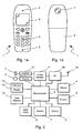
- FIG. 1a shows the front of a mobile communications device in the form of a mobile telephone handset 1, which is sometimes referred to as a cellular telephone handset.
- the handset 1 includes a microphone 2, keypad 3, liquid crystal display (LCD) 4 and speaker 5.
- the LCD 4 and speaker 5 form part of a user interface.
- FIG. 1b shows the reverse side of the handset 1.
- the handset 1 includes a detachable battery 6 for powering the handset 1 and a digital camera unit 7.
- the digital camera unit 7 is suitable for capturing still and moving images and comprises a lens, an image sensor, such as a complementary metal oxide semiconductor (CMOS) sensor and an analogue-to-digital (ADC) converter for supplying digital image data.
- CMOS complementary metal oxide semiconductor
- ADC analogue-to-digital
- Figure 2 illustrates circuitry included in the handset 1. Signal processing is carried out under the control of a digital microcontroller 8 which has an associated RAM/ROM 9 and flash memory 10. Electrical analogue audio signals are produced by the microphone 2 and amplified by a pre-amplifier 11. Similarly, analogue audio signals are fed to the speaker 5 through an amplifier 12.
- the microcontroller 8 receives instruction signals from the keypad 3 and controls operation of the LCD 4 and flash memory 10.
- a smart card 13 in the form of a GSM SIM card which contains the usual GSM international mobile subscriber identity and encryption K i that is used for encoding the radio transmission in a manner well known per se .
- the SIM card 13 is removably received in a SIM card reader 14. Radio signals are transmitted and received by means of the antenna 15 connected through a r.f. stage 16 to a codec 17 configured to process signals under the control of a microcontroller 8.
- Image data captured by the digital camera unit 7 is processed by the microcontroller 8 and held in flash memory 10.
- the flash memory 10 may be in the form of a removable "memory stick".
- the handset 1 may also be provided with a dedicated image processor (not shown) so as to reduce processing load on the microcontroller 8.
- the handset 1 may operate as a digital camera capable of capturing and storing still and/or moving pictures.
- FIG 3 shows LCD 4 when the handset 1 is in a camera state, which is sometimes known as "camera mode".
- An image 18, in this example a picture of a boat, is captured by the camera unit 7 ( Figure 1) and is displayed by the microcontroller 8 in an image window 19.
- the image window 19 includes an indicator 20 in the form of a three-level bar.
- the indicator 20 specifies whether the handset 1 is able to capture an image of optimum quality in terms of exposure, white balance and dark reference.
- the image 18 is provided with a header 21 which allow the user to label the image 18.
- the image window 19 is used as a viewfinder to help the user to compose a picture.
- the user directs the camera unit 7 ( Figure 1) at a subject or scene, while the handset 1 automatically performs exposure control, adjusts white balance and determines dark reference using algorithms which are known per se .
- the microprocessor 8 in conjunction with the camera unit 7, executes the algorithms.
- An exposure control algorithm which is often referred to as auto-exposure or simply "AE" is analogous to shutter speed control on a film camera, but in the case of a CMOS sensor it adjusts pixel integration time and the various gain blocks in the system to satisfy the luminance of the scene and, if appropriate, to reject flicker due to lighting running off an alternating current source.
- a white balance algorithm which is often referred to as auto-white balance or simply "AWB", attempts to adjust gains on the red, green and blue colour channels to correct imbalances caused by the spectral content of the scene illumination.
- a dark calibration algorithm attempts to subtract from a captured image the effects of dark current, which is the pixel leakage current. This quantity varies markedly with temperature. Information on the dark current is often derived from several rows or columns of pixels outside the usable image area which are masked to exclude ambient light.
- a stable solution to each algorithm is found by holding the handset 1 steady and allowing the handset 1 to try different conditions and settle on a set of solutions which represent an optimal image.
- the handset 1 will have difficulty determining the optimal image, if the subject or scene comprises for example moving objects or both high and low levels of lighting.
- the user is provided with feedback to indicate whether the handset 1 is ready to take a picture, i.e. whether the algorithms have converged, and, if not, to allow the user to take appropriate measures, such as holding the handset 1 steady.
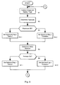
- Figure 4 shows a control register 22 comprising first, second and third flags 23a, 23b, 23c which represent whether or not a stable solution of each algorithm has been found.
- a flag set to "1" represents a stable solution.
- the user is informed by shading all three levels 20 1 , 20 2 , 20 3 of the indicator 20 ( Figure 3).
- none of the flags 23a, 23b, 23c are set, then none of the levels 20 1 , 20 2 , 20 3 are shaded.
- the microcontroller 8 then checks the state of the register 22.
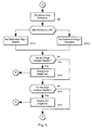
- the microcontroller 8 checks whether the three flags 23a, 23b, 23c of the register 22 are set to "stable" (step S11). If so, all three stages 20 1 , 20 2 , 20 3 of the indicator 20 are shaded (step 12). Thus, the indicator appears as a fully-filled vertical bar.
- the microcontroller 8 checks whether any two of the flags 23a, 23b, 23c are set to "stable" (step S13). If two flags are set, then first and second levels 20 1 , 20 2 of the indicator 20 are shaded (step S14). Thus, the indicator 20 appears as a bar which is two-thirds filled.
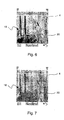
- An example of an LCD 4 showing a near-optimal quality image 18 is shown in Figure 7.
- the microcontroller 8 checks whether any one of the flags 23a, 23b, 23c is set to "stable" (step S15). If one of the flags 23a, 23b, 23c is set, then the first stage 20 1 of the indictor 20 is shaded (step S16). Thus, the indicator 20 appears as a bar which is only one-third filled.
- An example of an LCD 4 showing a poor quality image 18 is shown in Figure 8.
- step S17 If all of the tests fail and none of the flags 23a, 23b, 23c are set, then no part of the indicator 20 is shaded (step S17), as shown in Figure 9.
- the microcontroller 8 determines whether a key on the keypad 3 has been pressed (step S18). If a key has been pressed, then the image 18 is captured and stored in flash memory 10. Otherwise, the process returns to step S1.
- This process has the advantage that the user is provided with real-time feedback as to the quality of the image 18 being captured. If the image 18 is of poor quality, then further exposure control and/or white balancing and/or dark calibration is needed. This may be remedied by holding the camera steady for a period of time, such as a few seconds, or re-composing the picture.
- the microcontroller 8 performs the process described earlier under the control of a computer program stored in RAM/ROM 9, which is loaded and executed when handset 1 enters the camera state. It will be appreciated that the process may be executed by a dedicated image processor, which may itself be included in the camera unit 7.
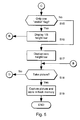
- the digital camera unit 7 includes a CMOS sensor 24 and an analogue-to-digital converter (ADC) 25.
- the CMOS sensor receives light 26 and generates a corresponding electrical signal 27 which is converted into an image signal 28.
- the image signal 28 is fed to the microcontroller 8 which operates display driving software 29 which provides a display signal 30 to the display 4.
- the microcontroller 8 executes first, second and third routines 31, 32, 33.
- the first routine 31 performs the exposure control algorithm which encompasses steps S2 to S4 of the process shown in Figure 5.
- the second routine 32 performs the white balancing algorithm which generally covers steps S5 to S7 of the process shown in Figure 5.
- the third routine 33 performs the dark reference algorithm which is broadly encompasses steps S8 to S10. While performing the algorithms, the microcontroller 8 exchanges signals 34, 35, 36 with the camera unit 7.
- the first routine 31 receives light levels and sends instructions regarding pixel integration time.
- the second routine 32 receives colour channel information and sends instructions to adjust gain for each colour channel.
- the third routine 33 receives information regarding pixel leakage and sends instructions to subtract this from the electrical signal 27.
- First, second and third algorithm results 37, 38, 39 are sent to the register 22.
- the register 22 is held in RAM, although it could be held in the controller's memory (not shown).
- the microcontroller 8 executes a fourth routine 40 which checks the content of the register 22 as outlined in steps S11 to S17 of the process shown in Figure 5.
- the fourth routine 40 produces a signal 41 which is fed to the display driver 29 for displaying the indicator 20 appropriate to the content of the register 22.
- step S2 to 10 and steps S11 to 17 need not be executed by the same processor and, in particular by the microcontroller 8.
- steps S2 to S10 may be performed by a processor embedded in the camera unit 7.
- the digital camera unit may be mounted anywhere on the handset, for example on the front side of the handset or connected to the handset via a cable.
- the image sensor may comprise a different type of sensor, such as a charge coupled device (CCD).
- CCD charge coupled device
- criteria may be used to determine whether an image is ready to be captured. These criteria may include numerical thresholds or ranges.
- the indicator may comprise multicoloured indicator.
- a green shape may signify a picture of optimal quality picture
- an amber shape may represent a near-optimal quality picture
- a red shape may indicate a poor-quality picture.
- the indicator may be multi-shaped.
- a tick or check may signify an optimal-quality picture.
- an audio signal may be provided as an indicator of image quality. This may comprise spoken words such as “ready” or “not ready”, different tunes or tones of varying pitch.
Landscapes
- Engineering & Computer Science (AREA)
- Multimedia (AREA)
- Signal Processing (AREA)
- Human Computer Interaction (AREA)
- Color Television Image Signal Generators (AREA)
- Studio Devices (AREA)
- Processing Of Color Television Signals (AREA)
- Telephone Function (AREA)
Abstract
Description
Claims (18)
- A digital camera including an image quality indicator.
- A digital camera according to claim 1, including a display for displaying an image together with said image quality indicator.
- A digital camera according to claim 1, wherein the image quality indicator indicates whether an image is optimal based on one or more image parameters.
- A digital camera according to claim 3, wherein said one or more image parameters includes light exposure.
- A digital camera according to claim 3, wherein said one or more image parameters includes white balance.
- A digital camera according to claim 3, wherein said one or more image parameters includes dark reference.
- A mobile communications device including a digital camera according to claim 1.
- A mobile telephone handset including a digital camera according to claim 1.
- A method of operating a digital camera comprising providing a user interface of said camera with an image quality indicator.
- A method according to claim 9, including capturing an image.
- A method according to claim 10, comprising displaying said captured image, together with said indicator.
- A method according to claim 10, further comprising executing one or more algorithms for determining the quality of said image.
- A method according to claim 12, wherein executing one or more algorithms for determining the quality of an image captured includes determining light exposure for said image.
- A method according to claim 12, wherein executing one or more algorithms for determining the quality of an image captured includes performing a white balance of said image.
- A method according to claim 12, wherein executing one or more algorithms for determining the quality of an image captured includes determining a dark reference for said image.
- A method according to claim 12, comprising determining whether said one or more algorithms have found a stable solution.
- A computer program for performing the method of claim 9.
- A digital camera comprising an image sensor, a conversion circuit for receiving signals from the image sensor and producing an image signal, a display for receiving the image signal and outputting an image corresponding to the image signal and a control circuit for controlling the image sensor, the conversion circuit and the display, wherein the control circuit includes a processor configured to determine quality of the image signal and to produce a signal for indicating to a user whether the image signal satisfies one or more image quality conditions.
Applications Claiming Priority (2)
| Application Number | Priority Date | Filing Date | Title |
|---|---|---|---|
| US20870 | 2001-12-19 | ||
| US10/020,870 US7286177B2 (en) | 2001-12-19 | 2001-12-19 | Digital camera |
Publications (2)
| Publication Number | Publication Date |
|---|---|
| EP1322109A2 true EP1322109A2 (en) | 2003-06-25 |
| EP1322109A3 EP1322109A3 (en) | 2004-04-14 |
Family
ID=21801035
Family Applications (1)
| Application Number | Title | Priority Date | Filing Date |
|---|---|---|---|
| EP02026064A Ceased EP1322109A3 (en) | 2001-12-19 | 2002-11-22 | Digital camera |
Country Status (3)
| Country | Link |
|---|---|
| US (1) | US7286177B2 (en) |
| EP (1) | EP1322109A3 (en) |
| CN (1) | CN1430402A (en) |
Cited By (6)
| Publication number | Priority date | Publication date | Assignee | Title |
|---|---|---|---|---|
| WO2004030378A3 (en) * | 2002-09-24 | 2004-04-29 | Imacon As | Image quality indicator |
| WO2004110055A1 (en) * | 2003-06-11 | 2004-12-16 | Nokia Corporation | A method and a system for image processing, a device, and an image record |
| EP1615428A1 (en) | 2004-07-06 | 2006-01-11 | LG Electronics, Inc. | Method and apparatus for adjusting exposure for a camera in a mobile phone |
| EP1739982A1 (en) * | 2005-06-30 | 2007-01-03 | Hasselblad A/S | An electronic camera with classification of images according to image quality |
| WO2007031605A1 (en) | 2005-09-15 | 2007-03-22 | Nokia Corporation | Trigger tone of a camera |
| EP2219369A3 (en) * | 2009-02-16 | 2013-06-26 | Lg Electronics Inc. | Method for processing image data in portable electronic device, and portable electronic device having camera thereof |
Families Citing this family (31)
| Publication number | Priority date | Publication date | Assignee | Title |
|---|---|---|---|---|
| US7362354B2 (en) * | 2002-02-12 | 2008-04-22 | Hewlett-Packard Development Company, L.P. | Method and system for assessing the photo quality of a captured image in a digital still camera |
| JP4198449B2 (en) * | 2002-02-22 | 2008-12-17 | 富士フイルム株式会社 | Digital camera |
| KR100663455B1 (en) * | 2002-04-22 | 2007-01-02 | 삼성전자주식회사 | Image display device and method according to ambient illumination. |
| KR100530746B1 (en) * | 2002-12-24 | 2005-11-23 | 삼성테크윈 주식회사 | Digital camera informing that photographing state was inadequate, and control method thereof |
| US20050030388A1 (en) * | 2003-08-06 | 2005-02-10 | Stavely Donald J. | System and method for improving image capture ability |
| US20060004698A1 (en) | 2004-06-30 | 2006-01-05 | Nokia Corporation | Automated prioritization of user data files |
| JP2006115446A (en) * | 2004-09-14 | 2006-04-27 | Seiko Epson Corp | Imaging apparatus and image evaluation method |
| US20060215042A1 (en) * | 2005-03-24 | 2006-09-28 | Motorola, Inc. | Image processing method and apparatus with provision of status information to a user |
| US9769354B2 (en) | 2005-03-24 | 2017-09-19 | Kofax, Inc. | Systems and methods of processing scanned data |
| KR100724426B1 (en) * | 2005-10-11 | 2007-06-04 | 엘지전자 주식회사 | Imaging Device and Method |
| US8081227B1 (en) * | 2006-11-30 | 2011-12-20 | Adobe Systems Incorporated | Image quality visual indicator |
| JP2009044240A (en) * | 2007-08-06 | 2009-02-26 | Nikon Corp | Electronic camera |
| JP5153512B2 (en) * | 2008-08-08 | 2013-02-27 | キヤノン株式会社 | Display processing apparatus, display processing method, program, and storage medium |
| KR101495079B1 (en) * | 2008-11-18 | 2015-02-24 | 삼성전자주식회사 | Method and apparatus for displaying scene information, and digital photographing apparatus thereof |
| US8125557B2 (en) * | 2009-02-08 | 2012-02-28 | Mediatek Inc. | Image evaluation method, image capturing method and digital camera thereof for evaluating and capturing images according to composition of the images |
| US9767354B2 (en) | 2009-02-10 | 2017-09-19 | Kofax, Inc. | Global geographic information retrieval, validation, and normalization |
| US9576272B2 (en) | 2009-02-10 | 2017-02-21 | Kofax, Inc. | Systems, methods and computer program products for determining document validity |
| US8421898B2 (en) * | 2010-07-27 | 2013-04-16 | Arcsoft (Hangzhou) Multimedia Technology Co., Ltd. | Method for detecting and showing quality of a preview or stored picture in an electronic imaging device |
| US10146795B2 (en) | 2012-01-12 | 2018-12-04 | Kofax, Inc. | Systems and methods for mobile image capture and processing |
| TWI492166B (en) * | 2012-01-12 | 2015-07-11 | Kofax Inc | System and method for capturing and processing motion images |
| US9355312B2 (en) | 2013-03-13 | 2016-05-31 | Kofax, Inc. | Systems and methods for classifying objects in digital images captured using mobile devices |
| US9208536B2 (en) | 2013-09-27 | 2015-12-08 | Kofax, Inc. | Systems and methods for three dimensional geometric reconstruction of captured image data |
| WO2014160426A1 (en) | 2013-03-13 | 2014-10-02 | Kofax, Inc. | Classifying objects in digital images captured using mobile devices |
| US20140316841A1 (en) | 2013-04-23 | 2014-10-23 | Kofax, Inc. | Location-based workflows and services |
| JP2016518790A (en) | 2013-05-03 | 2016-06-23 | コファックス, インコーポレイテッド | System and method for detecting and classifying objects in video captured using a mobile device |
| JP2016538783A (en) | 2013-11-15 | 2016-12-08 | コファックス, インコーポレイテッド | System and method for generating a composite image of a long document using mobile video data |
| US9760788B2 (en) | 2014-10-30 | 2017-09-12 | Kofax, Inc. | Mobile document detection and orientation based on reference object characteristics |
| US10242285B2 (en) | 2015-07-20 | 2019-03-26 | Kofax, Inc. | Iterative recognition-guided thresholding and data extraction |
| US9779296B1 (en) | 2016-04-01 | 2017-10-03 | Kofax, Inc. | Content-based detection and three dimensional geometric reconstruction of objects in image and video data |
| CN108174185B (en) * | 2016-12-07 | 2021-03-30 | 中兴通讯股份有限公司 | A photographing method, device and terminal |
| US10803350B2 (en) | 2017-11-30 | 2020-10-13 | Kofax, Inc. | Object detection and image cropping using a multi-detector approach |
Family Cites Families (10)
| Publication number | Priority date | Publication date | Assignee | Title |
|---|---|---|---|---|
| US5006878A (en) * | 1989-09-11 | 1991-04-09 | Eastman Kodak Company | Magnetic recording on film of beyond camera exposure value range indication |
| JPH0575966A (en) * | 1990-12-13 | 1993-03-26 | Nikon Corp | Electronic still camera |
| JPH04280584A (en) | 1991-03-08 | 1992-10-06 | Sharp Corp | Image pickup device |
| KR0128089Y1 (en) | 1993-08-18 | 1998-11-16 | 김광호 | View-finder with color vector display |
| US5666569A (en) | 1994-08-25 | 1997-09-09 | Flashpoint Technology, Inc. | System and method for detecting and indicating proper focal distance in a fixed lens camera |
| FI112837B (en) | 1999-10-26 | 2004-01-15 | Nokia Corp | Mobile station |
| JP4140181B2 (en) * | 2000-09-08 | 2008-08-27 | 富士フイルム株式会社 | Electronic camera |
| DE60239305D1 (en) | 2001-04-12 | 2011-04-14 | Ricoh Co Ltd | Imaging device |
| US6539177B2 (en) * | 2001-07-17 | 2003-03-25 | Eastman Kodak Company | Warning message camera and method |
| US6970199B2 (en) * | 2001-10-05 | 2005-11-29 | Eastman Kodak Company | Digital camera using exposure information acquired from a scene |
-
2001
- 2001-12-19 US US10/020,870 patent/US7286177B2/en not_active Expired - Fee Related
-
2002
- 2002-11-22 EP EP02026064A patent/EP1322109A3/en not_active Ceased
- 2002-12-19 CN CN02157040A patent/CN1430402A/en active Pending
Cited By (10)
| Publication number | Priority date | Publication date | Assignee | Title |
|---|---|---|---|---|
| WO2004030378A3 (en) * | 2002-09-24 | 2004-04-29 | Imacon As | Image quality indicator |
| WO2004110055A1 (en) * | 2003-06-11 | 2004-12-16 | Nokia Corporation | A method and a system for image processing, a device, and an image record |
| US8072509B2 (en) | 2003-06-11 | 2011-12-06 | Nokia Corporation | Method and a system for image processing, a device, and an image record |
| EP1615428A1 (en) | 2004-07-06 | 2006-01-11 | LG Electronics, Inc. | Method and apparatus for adjusting exposure for a camera in a mobile phone |
| US7526194B2 (en) | 2004-07-06 | 2009-04-28 | Lg Electronics Inc. | Method and apparatus for adjusting exposure for a camera |
| EP1739982A1 (en) * | 2005-06-30 | 2007-01-03 | Hasselblad A/S | An electronic camera with classification of images according to image quality |
| WO2007031605A1 (en) | 2005-09-15 | 2007-03-22 | Nokia Corporation | Trigger tone of a camera |
| EP1924885A4 (en) * | 2005-09-15 | 2010-08-11 | Nokia Corp | TONE OF TRIP OF A CAMERA |
| EP2219369A3 (en) * | 2009-02-16 | 2013-06-26 | Lg Electronics Inc. | Method for processing image data in portable electronic device, and portable electronic device having camera thereof |
| US8514315B2 (en) | 2009-02-16 | 2013-08-20 | Lg Electronics Inc. | Method for processing image data in portable electronic device, and portable electronic device having camera thereof |
Also Published As
| Publication number | Publication date |
|---|---|
| US7286177B2 (en) | 2007-10-23 |
| EP1322109A3 (en) | 2004-04-14 |
| CN1430402A (en) | 2003-07-16 |
| US20030112361A1 (en) | 2003-06-19 |
Similar Documents
| Publication | Publication Date | Title |
|---|---|---|
| US7286177B2 (en) | Digital camera | |
| US20080231726A1 (en) | Apparatus and method for image color correction in a portable device | |
| US7711257B2 (en) | Image quality in cameras using flash | |
| US7606476B2 (en) | Imaging device and imaging method | |
| US9426437B2 (en) | Image processor performing noise reduction processing, imaging apparatus equipped with the same, and image processing method for performing noise reduction processing | |
| KR102375688B1 (en) | Imaging device, shooting system and shooting method | |
| JP2007316599A (en) | Display control apparatus and display control program | |
| KR100609155B1 (en) | Image processing device and backlight correction method using same | |
| JP7764510B2 (en) | Image processing device, imaging device, image processing method, image processing program, and recording medium | |
| US7800655B2 (en) | Detecting abnormality of image capturing apparatus | |
| JP4282610B2 (en) | CAMERA, PORTABLE COMMUNICATION DEVICE EQUIPPED WITH THE CAMERA, SHOOTING METHOD AND PROGRAM | |
| KR100706383B1 (en) | Mobile communication terminal with digital imaging function and digital inspection method | |
| US20050128313A1 (en) | Photographing apparatus having a liquid-crystal display | |
| JP2015192152A (en) | White balance adjustment device, white balance adjustment method and imaging device | |
| JP2017147535A (en) | White balance adjustment device, white balance adjustment method, white balance adjustment program, and photographing device | |
| US20070058965A1 (en) | Camera system | |
| US20060072031A1 (en) | Mobile communication terminal equipped with digital image capturing module and method of capturing digital image | |
| JP4222130B2 (en) | White balance control device and electronic device | |
| JP2004158967A (en) | Mobile phone with imaging apparatus | |
| JP4440562B2 (en) | Video signal processing device | |
| JP2015192179A (en) | White balance adjusting device, photographing device, and white balance adjusting method | |
| JP2005033332A (en) | White balance control unit and electronic equipment | |
| JP2009302700A (en) | Imaging device, image processor and program | |
| JP2005136854A (en) | White balance control device and electronic device | |
| JP6875603B2 (en) | Imaging device, imaging method, and program |
Legal Events
| Date | Code | Title | Description |
|---|---|---|---|
| PUAI | Public reference made under article 153(3) epc to a published international application that has entered the european phase |
Free format text: ORIGINAL CODE: 0009012 |
|
| AK | Designated contracting states |
Designated state(s): AT BE BG CH CY CZ DE DK EE ES FI FR GB GR IE IT LI LU MC NL PT SE SK TR |
|
| AX | Request for extension of the european patent |
Extension state: AL LT LV MK RO SI |
|
| PUAL | Search report despatched |
Free format text: ORIGINAL CODE: 0009013 |
|
| AK | Designated contracting states |
Kind code of ref document: A3 Designated state(s): AT BE BG CH CY CZ DE DK EE ES FI FR GB GR IE IT LI LU MC NL PT SE SK TR |
|
| AX | Request for extension of the european patent |
Extension state: AL LT LV MK RO SI |
|
| 17P | Request for examination filed |
Effective date: 20041014 |
|
| AKX | Designation fees paid |
Designated state(s): AT BE BG CH CY CZ DE DK EE ES FI FR GB GR IE IT LI LU MC NL PT SE SK TR |
|
| 17Q | First examination report despatched |
Effective date: 20070514 |
|
| STAA | Information on the status of an ep patent application or granted ep patent |
Free format text: STATUS: THE APPLICATION HAS BEEN REFUSED |
|
| 18R | Application refused |
Effective date: 20120928 |