EP1322050A2 - Method and system for doubling the spectrum efficiency in a radio transmission system - Google Patents
Method and system for doubling the spectrum efficiency in a radio transmission system Download PDFInfo
- Publication number
- EP1322050A2 EP1322050A2 EP02292213A EP02292213A EP1322050A2 EP 1322050 A2 EP1322050 A2 EP 1322050A2 EP 02292213 A EP02292213 A EP 02292213A EP 02292213 A EP02292213 A EP 02292213A EP 1322050 A2 EP1322050 A2 EP 1322050A2
- Authority
- EP
- European Patent Office
- Prior art keywords
- signal
- antennas
- phase
- antenna
- shifted
- Prior art date
- Legal status (The legal status is an assumption and is not a legal conclusion. Google has not performed a legal analysis and makes no representation as to the accuracy of the status listed.)
- Granted
Links
- 230000005540 biological transmission Effects 0.000 title claims abstract description 22
- 238000001228 spectrum Methods 0.000 title claims abstract description 17
- 238000000034 method Methods 0.000 title claims abstract description 16
- 230000010287 polarization Effects 0.000 claims abstract description 12
- 239000000969 carrier Substances 0.000 claims abstract description 8
- 230000009977 dual effect Effects 0.000 claims abstract 2
- 230000010363 phase shift Effects 0.000 claims description 6
- 230000002457 bidirectional effect Effects 0.000 claims description 5
- 230000001427 coherent effect Effects 0.000 abstract description 4
- 230000000694 effects Effects 0.000 abstract description 4
- 238000005388 cross polarization Methods 0.000 description 5
- 230000033001 locomotion Effects 0.000 description 3
- 238000012986 modification Methods 0.000 description 3
- 230000004048 modification Effects 0.000 description 3
- 238000005286 illumination Methods 0.000 description 2
- 230000003534 oscillatory effect Effects 0.000 description 2
- 230000006978 adaptation Effects 0.000 description 1
- 238000010276 construction Methods 0.000 description 1
- 230000001419 dependent effect Effects 0.000 description 1
- 230000001066 destructive effect Effects 0.000 description 1
- 238000010586 diagram Methods 0.000 description 1
- 238000005562 fading Methods 0.000 description 1
Images



Classifications
-
- H—ELECTRICITY
- H04—ELECTRIC COMMUNICATION TECHNIQUE
- H04B—TRANSMISSION
- H04B7/00—Radio transmission systems, i.e. using radiation field
- H04B7/02—Diversity systems; Multi-antenna system, i.e. transmission or reception using multiple antennas
- H04B7/10—Polarisation diversity; Directional diversity
Definitions
- the present invention generally relates to radio transmissions and in particular to a radio transmission method and system having a high spectrum efficiency, evaluated in terms of transmission capacity of a radio channel.
- the radio transmissions are particularly attractive for their possibility of connecting two (or more) stations placed at high distances without the need to lay cables or wires between the stations.
- one of the limitations which afflects such a type of transmission is the spectrum efficiency, evaluated in terms of transmission capacity of a radio channel, that is rather reduced.
- several solutions, presently utilized, have been devised.
- the classic solution consists in increasing the complexity of modulation in the transmission step. In other words, a higher number of symbols is transmitted and in this way it is as if the transmitted bit/sec were increased.
- frequency re-use An alternative solution, which is also utilizable in association with the classic solution, consists in the so-called "frequency re-use".
- the known types of frequency reuse systems are: spatial frequency reuse; polar frequency reuse and angle frequency reuse.
- the main object of the present invention is providing a radio transmission system which has a spectrum efficiency increased vis-à-vis the one obtained by one or the other of the known solutions.
- the present invention provides a system which is different from all the known frequency reuse systems but it could be used in addition to (namely together with) the above known systems.
- a further object of the present invention is providing a radio transmission system with an increased spectrum efficiency which can be used in combination with the known solutions in order to supply a system with a more higher spectrum efficiency.
- the basic idea of the present invention is to exploit conveniently the interference phenomenon in order to transmit two different signals by utilizing, for each of them, carriers at the same frequency, by obtaining in this way a doubling of the spectrum efficiency, namely of the amount of information transmitted in the frequency band unit that is occupied.
- the present invention does not prevent the use, and really it could easily use, double polarization antennas (H & V or whichever type of orthogonal polarization) to obtain a more higher spectrum efficiency.
- the interference is a typical effect of waves propagation which occurs when two oscillatory motions having the same frequency and a constant phase difference travel through the same space-time region.
- Thomas Young was one of the first researchers to be interested in such a phenomenon, who was able to prove the ondulatory nature of light through it by confuting the corpuscular Newton theory.
- the experimental apparatus of Young consisted in a point and monochrome light source illuminating a screen with two small holes: owing to the Huygens principle, the holes acted as secondary sources of spherical coherent light waves, and during the construction step, so that the resulting light produced an interference. Downwards of holes, zones of maximum illumination and dark zones were observed, corresponding to the ventral and nodal zones.
- the basic idea of the present invention is based on the proper exploitation of the interference phenomenon to transmit two different signals, by utilizing for each of them carriers at the same frequency, thus obtaining in this way a double spectrum efficiency, namely a double amount of information transmitted within the occupied frequency band unit.
- Fig. 1.1 it is shown the case of a transmitter TX 1 transmitting a signal S through a carrier frequency P. If this signal is transmitted by two antennas a and b placed at a distance d one from each other, owing to the intereference phenomenon, on an hypothetical receiving front placed at a distance L or parallel to the connection of two antennas a and b, there will be zones of maximum reception of the transmitted signal ( Sa from the antenna a and Sb from the antenna b ) and zones of minimum reception. Only for a simpler description of the phenomenon, it is considered the case of the a parallel receiving front, but nothing is against considering whichever form or position of the receiving and transmitting fronts.
- zones of maximum and minimum are due to the fact that in these zones a wave emitted by two spatially separated points, therefore frequency-coherent and having the same (known) amplitude and the same phase, combines.
- the zones of maximum are those wherein two contributions are phase added, as they have traveled the same path or as the difference of traveled path is equal to integer multiples of half wave length (referred to the carrier frequency).
- the zones of minimum are the ones wherein the two contributions are counter-phase summed.
- the system geometry and the carrier frequency determine the distance between the minima and maxima which assumes the well known form shown in Fig. 1.3.
- Fig. 3.2 illustrates the frequency plan of the system of Fig. 3.1.
- a first, second, third and fourth transceivers ( RTX 1 , RTX 2 , RTX 3 , RTX 4 , respectively) that generate four corresponding signals ( S1, S2, S3, S4 ) and receive four signals ( S4, S3, S2, S1 );
- four phase shifters ( PSa, PSb, PSa', PSb' ) for phase-shifting, by a certain angle, the signals to be transmitted ( S2, S1, S4, S3 ) on the same carrier P 0 , thus obtaining four respective phase shifted signals ( S2*, S1*, S4*, S3* );
- four adders ( AD a , AD b , AD a' , AD b' ) for adding the non phase-shifted signals and the phase-shifted ones, thus obtaining sum signals ( S1+S2*, S2+S1*, S3+S4*, S4+S3* );
- four three-ports circulators ( CR a
- the signal S1 is transmitted on the carrier P 0 from antenna a and the same signal S1 is transmitted on the carrier P 0 from antenna b but it is phase-shifted by a certain angle Q; on the receiving front, S1 shall have an absolute maximum in a' (output of circulator CR a' ) and an absolute minimum in b' .
- the signal S2 is transmitted on the same carrier P 0 from antenna b and the same signal S2 is transmitted from antenna a but it is phase-shifted by a certain angle Q' ; on the receiving front, S2 will have an absolute maximum in b' (output of circulator CR b' ) and an aboslute minimum in a'.
- the signal S3 is transmitted on the carrier P 1 and from the antenna b' the same signal S3 is transmitted on the carrier P 1 but phase-shifted by a certain angle Q; on the receiving front, S3 will have an absolute maximum in a (output of the circulator CRa ) and an absolute minimum in b .
- the signal S4 is transmitted on the same carrier P 1 and from the antenna a' the same signal S4 is transmitted but it is phase-shifted by a certain angle Q' ; on the receiving front, S4 will have an absolute maximum in b (output of the circulator CR b ) and an absolute minimum in a .
- the system according to the present invention should be considered as belonging to the family of frequency re-use systems.
- the main characteristic of the present system is to be compatible with the cross-polarization systems, namely that the two systems are utilizable as alternatives, but also combined one with each other, thus obtaining excellent benefits in terms of spectrum efficiency.
- the system illustrated in Figs.5 and 6 illustrates the concepts according to the present invention when combined with the concepts of the cross-polarization.
- the signal S6 H is also transmitted on the H-polarized carrier P 0 and from the antenna b the same signal S6 H is also transmitted on the carrier P 0 but phase-shifted by a certain angle Q' (possibly also equal to Q); on the receiving front, S6 H will have an absolute maximum in b' on the H polarization (output from the circulator CR b'H ) and an absolute minimum in a' .
- Q' possibly also equal to Q
- S6 H will have an absolute maximum in b' on the H polarization (output from the circulator CR b'H ) and an absolute minimum in a' .
- the same will occur for the other signals S2V, S3V, ... S8V; S1V, S2V, ...S8V , as it could be easily understood from the Figures 5 and 6.
- the capacity of a single radio cahnnel is even quadrupled vis-à-vis a single radio channel without cross-polarization.
- the path length L is to be understood as a distance between the plane of transmitting antennas (trasmitting wave front) and the plane of receiving antennas (receiving wave front). It is only for reasons of convenience that it is considered only the case of antennas placed one in front of the other as in the bottom antenna arrangement of Fig. 2.3. In case the antennas are arranged as in Fig. 2.1, it is necessary to perform different shifts on the signals.
- the only project parameter can be the distance d between the antennas.
- the transmitting/receiving antennas can be indifferently placed horizontally (side-by-side) or vertically (one above the other). Nevertheless, it is preferable to mount them horizontally to avoid that the propagation phenomena, which depend on the altitude, give problems and interfere with the results.
- the difference of paths covered by the signals can be of whichever entity (but multiple of ⁇ /2 vis-à-vis the carrier wavelength), such a path difference is to be considered limited to few multiples of carrier wavelength so that there are no attenuation path differences and propagation differences from the point of view of phase so that the modulating signal remains coherent.
- the phase differences of carrier are to be unsignificant from the point of view of the signal envelope (symbol time and so on).
Landscapes
- Engineering & Computer Science (AREA)
- Computer Networks & Wireless Communication (AREA)
- Signal Processing (AREA)
- Radio Transmission System (AREA)
- Transmitters (AREA)
- Radio Relay Systems (AREA)
- Variable-Direction Aerials And Aerial Arrays (AREA)
Abstract
Description
- The present invention generally relates to radio transmissions and in particular to a radio transmission method and system having a high spectrum efficiency, evaluated in terms of transmission capacity of a radio channel.
- As it is known, the radio transmissions are particularly attractive for their possibility of connecting two (or more) stations placed at high distances without the need to lay cables or wires between the stations. Nevertheless, one of the limitations which afflects such a type of transmission is the spectrum efficiency, evaluated in terms of transmission capacity of a radio channel, that is rather reduced. In order to increase the spectrum efficiency, several solutions, presently utilized, have been devised.
- The classic solution consists in increasing the complexity of modulation in the transmission step. In other words, a higher number of symbols is transmitted and in this way it is as if the transmitted bit/sec were increased.
- An alternative solution, which is also utilizable in association with the classic solution, consists in the so-called "frequency re-use". The known types of frequency reuse systems are: spatial frequency reuse; polar frequency reuse and angle frequency reuse.
- The main object of the present invention is providing a radio transmission system which has a spectrum efficiency increased vis-à-vis the one obtained by one or the other of the known solutions. The present invention provides a system which is different from all the known frequency reuse systems but it could be used in addition to (namely together with) the above known systems.
- A further object of the present invention is providing a radio transmission system with an increased spectrum efficiency which can be used in combination with the known solutions in order to supply a system with a more higher spectrum efficiency.
- These and further objects are obtained by a method and a system having the features set forth in the
Claims - The basic idea of the present invention is to exploit conveniently the interference phenomenon in order to transmit two different signals by utilizing, for each of them, carriers at the same frequency, by obtaining in this way a doubling of the spectrum efficiency, namely of the amount of information transmitted in the frequency band unit that is occupied.
- Practically, it is transmitted the same signal from two different antennas in order to have two coherent sources of signal. In this way, at the receiving front there are two points of maximum and two points of minimum of this signal. If the original signal is properly shifted with an antenna with respect to the other one, the effect will be in the possibility to place the maxima and minima at the receiving front in a corresponding way (and therefore freely).
- The present invention does not prevent the use, and really it could easily use, double polarization antennas (H & V or whichever type of orthogonal polarization) to obtain a more higher spectrum efficiency.
- There now follow a detailed description of the present invention, given as an example and not as a limitation, to be read with reference to the attached drawings, wherein:
- Fig. 1.1 shows a radio transmission system for transmitting a signal S through a carrier frequency P;
- Fig. 1.2 shows the frequency plan of the system of Fig. 1.1;
- Fig. 1.3 shows, for a particular system configuration, a diagram with the field value in ordinate versus the distance between the reception points in abscissa;
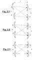
- Fig. 2 illustrates the receiving/transmitting fronts (first front and second front) and the mutual position of antennas;
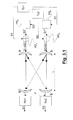
- Fig. 3.1 shows an unidirectional radio transmission system according to the present invention;
- Fig. 3.2 shows the frequency plan of system of Fig. 3.1;
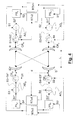
- Fig. 4 shows a bidirectional radio transmission system according to the present invention;
- Fig. 5 shows a bidirectional radio transmission system with orthogonal cross-polarization according to the present invention; and
- Fig. 6 is a completion of Fig. 5.
- The interference is a typical effect of waves propagation which occurs when two oscillatory motions having the same frequency and a constant phase difference travel through the same space-time region. Thomas Young was one of the first researchers to be interested in such a phenomenon, who was able to prove the ondulatory nature of light through it by confuting the corpuscular Newton theory. The experimental apparatus of Young consisted in a point and monochrome light source illuminating a screen with two small holes: owing to the Huygens principle, the holes acted as secondary sources of spherical coherent light waves, and during the construction step, so that the resulting light produced an interference. Downwards of holes, zones of maximum illumination and dark zones were observed, corresponding to the ventral and nodal zones.
- The theoretical understanding of the phenomenon is based on a simple law for composition of amplitudes of the oscillatory motions: the amplitudes produced by each hole at a point P, far r1 from the first hole and r2 from the second one, can be written as:
x - The above is a general effect which is applied without any particular modifications to whichever ondulatory motion, and in particular also to the propagation of the radio waves.
- The basic idea of the present invention is based on the proper exploitation of the interference phenomenon to transmit two different signals, by utilizing for each of them carriers at the same frequency, thus obtaining in this way a double spectrum efficiency, namely a double amount of information transmitted within the occupied frequency band unit.
- In Fig. 1.1 it is shown the case of a transmitter TX1 transmitting a signal S through a carrier frequency P. If this signal is transmitted by two antennas a and b placed at a distance d one from each other, owing to the intereference phenomenon, on an hypothetical receiving front placed at a distance L or parallel to the connection of two antennas a and b, there will be zones of maximum reception of the transmitted signal (Sa from the antenna a and Sb from the antenna b) and zones of minimum reception. Only for a simpler description of the phenomenon, it is considered the case of the a parallel receiving front, but nothing is against considering whichever form or position of the receiving and transmitting fronts. As hereunder shown, there are points of absolute maximum of reception with a surrounding, where the reception is kept high and points of absolute minimum of reception, where the reception is null, with a surrounding where the reception is kept low. An example of the value of the received field in the case of a carrier at 38 GHz on a
link L 3 Km long with two antennas a and b placed at a distance d equal to 4,2 m one from each other, which emit signals in phase, is illustrated in Fig. 1.3. In Fig. 1.3, at the ordinate there is the value of the relative field (0 dB being the point of maximum received on the wave front) and at the abscissa there is the distance between the receiving points. - The presence of zones of maximum and minimum is due to the fact that in these zones a wave emitted by two spatially separated points, therefore frequency-coherent and having the same (known) amplitude and the same phase, combines. The zones of maximum are those wherein two contributions are phase added, as they have traveled the same path or as the difference of traveled path is equal to integer multiples of half wave length (referred to the carrier frequency). The zones of minimum are the ones wherein the two contributions are counter-phase summed. The system geometry and the carrier frequency determine the distance between the minima and maxima which assumes the well known form shown in Fig. 1.3.
- All this is valid under the hypothesis that both the sources in a and b emit the waves at the same phase. It is easy to understand that in case of artificial phase shift before the emission of the wave by only one of the sources, it is possible to modify the positions of maxima and minima at the receiving front.
- With reference to Fig. 3.1, it is supposed that:
- a signal S1 is transmitted from antenna a (outgoing from the transmitter TX1 ) on the carrier P0 and the same signal S1 is transmitted from the antenna b on the carrier P0 but such a signal is phase-inverted by a certain angle Q (through the delay cell or phase shifter PSb) in order to obtain an absolute maximum in a' and an absolute minimum in b' at the receiving front;
- a signal S2 is transmitted from antenna b (outgoing from the transmitter TX2 ) on the carrier P0 and the same signal S2 is transmitted from the antenna a but such a signal is phase-inverted by a certain angle Q' (through the phase shifter PSa) in order to obtain an absolute maximum in b' and an absolute minimum in a' at the receiving front.
- This results in that a receiver RX1 placed at a' receives only the signal S1 and a receiver RX2 placed in b' receives only the signal S2. Thus, we have transmitted and received two signals by utilizing the same carrier P0 and therefore by occupying the very same frequency band which would be occupied by a single transmission, by doubling the spectrum efficiency. Fig. 3.2 illustrates the frequency plan of the system of Fig. 3.1.
- It could be demonstrated that it is possible to fix the distance d' between the receiving antennas a' and b' as the distance d between the transmission antennas a and b in order to implement the bidirectional transmission system shown in Fig. 4.
- In the system of Fig. 4 there are: a first, second, third and fourth transceivers (RTX1, RTX2, RTX3, RTX4 , respectively) that generate four corresponding signals (S1, S2, S3, S4) and receive four signals (S4, S3, S2, S1); four phase shifters (PSa, PSb, PSa', PSb') for phase-shifting, by a certain angle, the signals to be transmitted (S2, S1, S4, S3) on the same carrier P 0, thus obtaining four respective phase shifted signals (S2*, S1*, S4*, S3*); four adders (ADa, ADb, ADa', ADb' ) for adding the non phase-shifted signals and the phase-shifted ones, thus obtaining sum signals (S1+S2*, S2+S1*, S3+S4*, S4+S3*); four three-ports circulators (CRa, CRb, CRa', CRb' ); and, of course, four antennas (a, b, a', b'). The circulators could be also diplexers or whichever device which permits to discriminate transmitted and received signals.
- In the system of Fig. 4, the signal S1 is transmitted on the carrier P 0 from antenna a and the same signal S1 is transmitted on the carrier P0 from antenna b but it is phase-shifted by a certain angle Q; on the receiving front, S1 shall have an absolute maximum in a' (output of circulator CRa' ) and an absolute minimum in b'. The signal S2 is transmitted on the same carrier P 0 from antenna b and the same signal S2 is transmitted from antenna a but it is phase-shifted by a certain angle Q'; on the receiving front, S2 will have an absolute maximum in b' (output of circulator CRb' ) and an aboslute minimum in a'. From the antenna a' the signal S3 is transmitted on the carrier P1 and from the antenna b' the same signal S3 is transmitted on the carrier P1 but phase-shifted by a certain angle Q; on the receiving front, S3 will have an absolute maximum in a (output of the circulator CRa) and an absolute minimum in b. Finally, from the antenna b' the signal S4 is transmitted on the same carrier P1 and from the antenna a' the same signal S4 is transmitted but it is phase-shifted by a certain angle Q'; on the receiving front, S4 will have an absolute maximum in b (output of the circulator CRb ) and an absolute minimum in a.
- It is known a "cross-polarization" method usually indicated as "frequency re-use" which obtains a result which is similar to the one according to the present invention. It exploits the orthogonality between the wave polarizations. In particular, it utilizes the vertical polarization (or the right-hand circular polarization) for transmitting the first signal and the horizontal polarization (or the left hand circular polarization) for transmitting the second signal.
- In all respects, the system according to the present invention should be considered as belonging to the family of frequency re-use systems. The main characteristic of the present system is to be compatible with the cross-polarization systems, namely that the two systems are utilizable as alternatives, but also combined one with each other, thus obtaining excellent benefits in terms of spectrum efficiency. The system illustrated in Figs.5 and 6 illustrates the concepts according to the present invention when combined with the concepts of the cross-polarization.
- In the system of Figures 5 and 6, from the antenna a the signal S1V is transmitted on the V-polarized carrier P0 and from the antenna b the same signal S1V is transmitted on the carrier P0 but phase-shifted by a certain angle Q (namely S1V*); on the receiving front, S1V will have an absolute maximum in a' on the V polarization (output from the circulator CRa'V ) and an absolute minimum in b'. From the antenna a, the signal S6H is also transmitted on the H-polarized carrier P0 and from the antenna b the same signal S6H is also transmitted on the carrier P0 but phase-shifted by a certain angle Q' (possibly also equal to Q); on the receiving front, S6H will have an absolute maximum in b' on the H polarization (output from the circulator CRb'H ) and an absolute minimum in a'. The same will occur for the other signals S2V, S3V, ... S8V; S1V, S2V, ...S8V, as it could be easily understood from the Figures 5 and 6.
- Through the combination of the known frequency re-use concepts with the ones according to the present invention, the capacity of a single radio cahnnel is even quadrupled vis-à-vis a single radio channel without cross-polarization.
- Anyway, the involved variables to be set are: the distances (d, d') between the transmitting and receiving antennas and the link length (L) between the transmission and reception fronts. Since we are interested in a reciprocal system, it shall be considered d=d'; therefore, the only parameters involved shall be the distance between the antennas (d) and the link length (L), always in connection with the wavelength of the carrier.
- With reference to the various Figures 2, it should be noted that the path length L is to be understood as a distance between the plane of transmitting antennas (trasmitting wave front) and the plane of receiving antennas (receiving wave front). It is only for reasons of convenience that it is considered only the case of antennas placed one in front of the other as in the bottom antenna arrangement of Fig. 2.3. In case the antennas are arranged as in Fig. 2.1, it is necessary to perform different shifts on the signals.
- Since that the link length is generally fixed, the only project parameter can be the distance d between the antennas. For this purpose, the transmitting/receiving antennas can be indifferently placed horizontally (side-by-side) or vertically (one above the other). Nevertheless, it is preferable to mount them horizontally to avoid that the propagation phenomena, which depend on the altitude, give problems and interfere with the results.
- In other words, if the antennas are placed at the same altitude, there are high chances to avoid differential fading problems which could result in different propagations on parallel links. It is true that the signals have to reach the receiving antennas with the same phase but also the amplitude has to be the same, otherwise, their phase shifted sum is not null, namely it does not result in the cancellation.
- In the various Figures 3.1, 4 and 5 it has been decided to phase-shift only one of the signals transmitted through an antenna. For instance, in Fig. 3.1, the antenna a transmits a phase-shifted signal (S2*) and a non phase-shifted signal (S1). Nevertheless there is nothing against the possibility to phase-shift also S1 in order to compensate differences of signal path. It is always important to have a global phase shift so that the signals received be phase added at an antenna while are phase shift added at the other antenna. Therefore, the phase shiting can be artificially set (through the phase shifters) or by changing the path. Generically, it could be said (with reference to Fig. 3.1, for instance) that the phase shifting provided by PSa is a relative phase shifting.
- Although, as a general rule, in order to implement the present invention, the difference of paths covered by the signals can be of whichever entity (but multiple of λ/2 vis-à-vis the carrier wavelength), such a path difference is to be considered limited to few multiples of carrier wavelength so that there are no attenuation path differences and propagation differences from the point of view of phase so that the modulating signal remains coherent. In other words, the phase differences of carrier are to be unsignificant from the point of view of the signal envelope (symbol time and so on).
- It is evident that, in view of the present description and the enclosed drawings, different uses of the present invention as well as several variants, modifications, adaptations and replacements of parts by functionally equivalent components could become apparent for a man skilled in the art. Nevertheless, these new uses, variants, modifications, amendments and replacement of parts should be considered as within the scope of the invention which is loimited only by the attached following claims.
Claims (12)
- Method for increasing the spectrum efficiency in a point to point radio transmission system, wherein said method comprises the steps of:wherein said fronts are separated by a length (L), and is characterized by the steps of:providing a first front comprising a first and a second antennas (a, b; a', b'), said antennas being at a certain distance (d; d') one from each other;providing a second front comprising a first and a second antennas (a', b'; a, b), said antennas being at a certain distance (d'; d) one from each other,wherein said signals are transmitted by utilizing carriers at the same frequency, and wherein the difference of the distances between an antenna of the second front (a', b'; a, b) and the two antennas of the first front (a, b; a', b') results in a further phase-shift of carriers so that, at the first antenna of the second front, the sum of the first signal and of the second phase shifted signal is in phase while, at the second antenna of the second front, such a sum is in counter phase.feeding the first antenna (a; a') of the first front with a first signal (S1, S1V, S6H; S3, S3V, S7H ) and a second signal (S2*, S2V*, S5H*; S4*, S4V*, S8H*) phase-shifted by a certain angle (Q);feeding the second antenna (b, b') of the first front with the second signal (S2, S2V, S5H; S4, S4V, S8H ) and the first signal (S1*, S1V*, S6H*; S3*, S3V*, S7H*) phase-shifted by a certain angle (Q'),
- Method according to claim 1, characterized in that the phase shifting angle (Q, Q') of the first signal or of the second signal is null.
- Method according to claim 1, characterized in that the phase shifting angle (Q) of the first signal is equal to the phase shifting angle (Q') of the second signal.
- Method according to claim 1, characterized in that said step of feeding the first antenna (a; a') of the first front with a first signal comprises the step of feeding the first antenna of the first front with a first phase shifted signal.
- Method according to claim 1, characterized in that said step of feeding the second antenna (b, b') of the frist front with the second signal comprises the step of feeding the second antenna of the first front with a second phase-shifted signal.
- Method according to claim 1, characterized in that said transmission system is bidirectional, the distance between the antennas (a, b; a', b') of the first front being equal to the distance between the antennas (a', b'; a, b) of the second front.
- Method according to claim 6, characterized in that it comprises the further step of receiving, through said first and second antennas (a, b; a', b') of the first front, a third (S3, S3V, S7H; S1, S1V, S5H ) and a fourth signal (S4, S4V, S8H; S2, S2V, S6H ), respectively, sent through the antennas (a', b'; a, b) belonging to the second front.
- Method according to claim 7, characterized in that the third signal (S3, S3V, S7H; S1, S1V, S5H ) is transmitted together with the fourth phase-shifted signal (S4*, S4V*, S8H*; S2*, S2V*, S6H*) and said fourth signal (S4, S4V, S8H; S2, S2V, S6H ) is transmitted together with the third phase-shifted signal (S3*, S3V*, S7H*; S1*, S1V*, S5H*), wherein said third and fourth signals are transmitted by utilizing carriers at the same frequency.
- Method according to any of claims 1-8, characterized in that said antennas (a, b, a', b') are dual polarization (H, V) transmitting/receiving antennas, said first signal comprising a polarized signal (S1V, S3V ) and a differently polarized signal (S6H, S7H ), said second signal comprising a polarized signal (S2V, S4V ) and a differently polarized signal (S5H, S8H ).
- Point-to-point radio transmission system providing an increased spectrum efficiency, wherein the system comprises:characterized in that:a first front comprising a first and a second antennas (a, b; a', b'), said antennas being spaced by a certain distance (d; d') one from each other;a second front which comprises a first and a second antennas (a', b'; a, b), said antennas being spaced by a certain distance (d'; d) one from each other, said fronts are separated by a length (L), the system beingwherein said signals are transmitted by utilizing carriers at the same frequency, and wherein the difference of distances between an antenna of the second front (a', b'; a, b) and the two antennas of the first front (a, b; a', b') results in a further phase shifting of carriers, so that at the first antenna of the second front, the sum of the first signal and of the second phase shifted signal is in phase and, at the second antenna of the second front, it is in counter-phase.the first antenna (a; a') of the first front is fed by a first signal (S1, S1V, S6H; S3, S3V, S7H ) and a second signal (S2*, S2V*, S5H*; S4*, S4V*, S8H*) that is phase-shifted by a certain angle (Q);the second antenna (b, b') of the first front is fed by the second signal (S2, S2V, S5H; S4, S4V, S8H ) and the first signal (S1*, S1V*, S6H*; S3*, S3V*, S7H*) phase-shifted by a certain angle (Q'),
- System according to claim 10, characterized in that it is a bidirectional system, the distance between the antennas (a, b; a', b') of the frist front being equal to the distance between the antennas (a', b'; a, b) of the second front.
- System according to claim 11, characterized by comprising circulators for receiving, through said first and second antennas (a, b; a', b') of the first front, a third (S3, S3V, S7H; S1, S1V, S5H ) and a fourth signal (S4, S4V, S8H; S2, S2V, S6H ), respectively, sent through the antennas (a', b'; a, b) belonging to the second front.
Applications Claiming Priority (2)
| Application Number | Priority Date | Filing Date | Title |
|---|---|---|---|
| ITMI20012685 | 2001-12-19 | ||
| IT2001MI002685A ITMI20012685A1 (en) | 2001-12-19 | 2001-12-19 | METHOD AND SYSTEM TO DOUBLE THE SPECTRAL EFFICIENCY INHUN RADIO TRANSMISSION SYSTEMS |
Publications (3)
| Publication Number | Publication Date |
|---|---|
| EP1322050A2 true EP1322050A2 (en) | 2003-06-25 |
| EP1322050A3 EP1322050A3 (en) | 2005-03-23 |
| EP1322050B1 EP1322050B1 (en) | 2010-12-15 |
Family
ID=11448706
Family Applications (1)
| Application Number | Title | Priority Date | Filing Date |
|---|---|---|---|
| EP02292213A Expired - Lifetime EP1322050B1 (en) | 2001-12-19 | 2002-09-10 | Method and system for doubling the spectrum efficiency in a radio transmission system |
Country Status (5)
| Country | Link |
|---|---|
| US (1) | US6954619B2 (en) |
| EP (1) | EP1322050B1 (en) |
| AT (1) | ATE492075T1 (en) |
| DE (1) | DE60238594D1 (en) |
| IT (1) | ITMI20012685A1 (en) |
Families Citing this family (10)
| Publication number | Priority date | Publication date | Assignee | Title |
|---|---|---|---|---|
| US6862456B2 (en) * | 2002-03-01 | 2005-03-01 | Cognio, Inc. | Systems and methods for improving range for multicast wireless communication |
| US6785520B2 (en) * | 2002-03-01 | 2004-08-31 | Cognio, Inc. | System and method for antenna diversity using equal power joint maximal ratio combining |
| EP1769585A4 (en) * | 2002-03-01 | 2009-12-02 | Ipr Licensing Inc | System and method for joint maximal ratio combining using time-domain based signal processing |
| US6687492B1 (en) * | 2002-03-01 | 2004-02-03 | Cognio, Inc. | System and method for antenna diversity using joint maximal ratio combining |
| EP1595329B1 (en) * | 2002-03-21 | 2010-05-26 | IPR Licensing Inc. | Improving the efficiency of power amplifiers in devices using transmit beamforming |
| US6871049B2 (en) * | 2002-03-21 | 2005-03-22 | Cognio, Inc. | Improving the efficiency of power amplifiers in devices using transmit beamforming |
| US7006804B1 (en) * | 2002-07-10 | 2006-02-28 | At&T Corp. | High-speed two-way point-to-point transmission |
| DK1540830T3 (en) * | 2002-07-30 | 2009-05-04 | Ipr Licensing Inc | Multi-input (MIMO) radio communication system and method |
| CA2449751A1 (en) * | 2002-11-29 | 2004-05-29 | Creative Signal Solutions Inc. | A method, apparatus and system for multiple signal transmission, reception, and restoration |
| US7099678B2 (en) * | 2003-04-10 | 2006-08-29 | Ipr Licensing, Inc. | System and method for transmit weight computation for vector beamforming radio communication |
Citations (2)
| Publication number | Priority date | Publication date | Assignee | Title |
|---|---|---|---|---|
| US4791428A (en) | 1987-05-15 | 1988-12-13 | Ray J. Hillenbrand | Microwave receiving antenna array having adjustable null direction |
| US5898362A (en) | 1997-06-02 | 1999-04-27 | Motorola, Inc. | System for transmitting and receiving polarized CDMA signals and method of operation thereof |
Family Cites Families (9)
| Publication number | Priority date | Publication date | Assignee | Title |
|---|---|---|---|---|
| JP2845250B2 (en) * | 1992-01-31 | 1999-01-13 | 日本電気株式会社 | Cross polarization interference compensator |
| DE4303355A1 (en) * | 1993-02-05 | 1994-08-11 | Philips Patentverwaltung | Radio system |
| US6125109A (en) * | 1998-02-24 | 2000-09-26 | Repeater Technologies | Delay combiner system for CDMA repeaters and low noise amplifiers |
| US6459740B1 (en) * | 1998-09-17 | 2002-10-01 | At&T Wireless Services, Inc. | Maximum ratio transmission |
| US20020150070A1 (en) * | 1999-07-02 | 2002-10-17 | Shattil Steve J. | Method and apparatus for using frequency diversity to separate wireless communication signals |
| US6658269B1 (en) * | 1999-10-01 | 2003-12-02 | Raytheon Company | Wireless communications system |
| US6788661B1 (en) * | 1999-11-12 | 2004-09-07 | Nikia Networks Oy | Adaptive beam-time coding method and apparatus |
| US6771706B2 (en) * | 2001-03-23 | 2004-08-03 | Qualcomm Incorporated | Method and apparatus for utilizing channel state information in a wireless communication system |
| US6785520B2 (en) * | 2002-03-01 | 2004-08-31 | Cognio, Inc. | System and method for antenna diversity using equal power joint maximal ratio combining |
-
2001
- 2001-12-19 IT IT2001MI002685A patent/ITMI20012685A1/en unknown
-
2002
- 2002-09-10 EP EP02292213A patent/EP1322050B1/en not_active Expired - Lifetime
- 2002-09-10 AT AT02292213T patent/ATE492075T1/en not_active IP Right Cessation
- 2002-09-10 DE DE60238594T patent/DE60238594D1/en not_active Expired - Lifetime
- 2002-09-16 US US10/243,748 patent/US6954619B2/en not_active Expired - Lifetime
Patent Citations (2)
| Publication number | Priority date | Publication date | Assignee | Title |
|---|---|---|---|---|
| US4791428A (en) | 1987-05-15 | 1988-12-13 | Ray J. Hillenbrand | Microwave receiving antenna array having adjustable null direction |
| US5898362A (en) | 1997-06-02 | 1999-04-27 | Motorola, Inc. | System for transmitting and receiving polarized CDMA signals and method of operation thereof |
Also Published As
| Publication number | Publication date |
|---|---|
| EP1322050A3 (en) | 2005-03-23 |
| DE60238594D1 (en) | 2011-01-27 |
| US20030114108A1 (en) | 2003-06-19 |
| ATE492075T1 (en) | 2011-01-15 |
| EP1322050B1 (en) | 2010-12-15 |
| ITMI20012685A1 (en) | 2003-06-19 |
| US6954619B2 (en) | 2005-10-11 |
Similar Documents
| Publication | Publication Date | Title |
|---|---|---|
| Lin et al. | Refracting RIS-aided hybrid satellite-terrestrial relay networks: Joint beamforming design and optimization | |
| Toka et al. | RIS-empowered LEO satellite networks for 6G: Promising usage scenarios and future directions | |
| US9572038B2 (en) | Full duplex wireless transmission with channel phase-based encryption | |
| US7697958B2 (en) | Wireless repeater | |
| US20150048977A1 (en) | Antenna System and Method for Full Duplex Wireless Transmission with Channel Phase-Based Encryption | |
| US3757335A (en) | Communication and control system | |
| US20170188322A1 (en) | Solution with massive spatial distributing for telecom constellation | |
| US6954619B2 (en) | Method and system for doubling the spectrum efficiency in a radio transmission system by transmitting the same signal from two different antennas | |
| WO2015159808A1 (en) | Radio communication device and radio communication system | |
| KR950704866A (en) | DUAL DISTRIBUTIED ANTENNA SYSTEM | |
| SE9202541D0 (en) | RADIO RECEIVERS, RADIO TRANSMITTERS FOR COMMUNICATION WITH A RECEIVER HAVING A FOREIGNER, AND A REPEATER FOR RECEIVING SIGNALS FROM A MAIN TRANSMITTER | |
| WO1986007514A1 (en) | Digital communication equipment | |
| US20070279284A1 (en) | Method To Design Polarization Arrangements For Mimo Antennas Using State Of Polarization As Parameter | |
| US20160261308A1 (en) | Architecture for cancelling self interference and enabling full duplex communications | |
| Yu et al. | Secure-ISAC: Secure V2X communication: An integrated sensing and communication perspective | |
| US3144647A (en) | Diversity system | |
| Shattil et al. | Array control systems for multicarrier protocols using a frequency-shifted feedback cavity | |
| JP6482730B2 (en) | Wireless communication system | |
| Ibrahim et al. | Joint polarization and spatial modulation using reconfigurable intelligent surface | |
| CA2612711C (en) | A point-to-point telecommunications system | |
| EP3033806A1 (en) | Antenna system and method for full duplex wireless transmission with channel phase-based encryption | |
| US20080240279A1 (en) | Method and Device For Operating Mimo Air Interfaces in Mobile Communications Systems | |
| JP2011044759A (en) | Diversity reception system | |
| Salam et al. | Performance comparison of IRS and DF relay assisted mixed RF-underwater optical communication system | |
| RU2233028C2 (en) | Space-division radio link |
Legal Events
| Date | Code | Title | Description |
|---|---|---|---|
| PUAI | Public reference made under article 153(3) epc to a published international application that has entered the european phase |
Free format text: ORIGINAL CODE: 0009012 |
|
| AK | Designated contracting states |
Designated state(s): AT BE BG CH CY CZ DE DK EE ES FI FR GB GR IE IT LI LU MC NL PT SE SK TR |
|
| AX | Request for extension of the european patent |
Extension state: AL LT LV MK RO SI |
|
| PUAL | Search report despatched |
Free format text: ORIGINAL CODE: 0009013 |
|
| AK | Designated contracting states |
Kind code of ref document: A3 Designated state(s): AT BE BG CH CY CZ DE DK EE ES FI FR GB GR IE IT LI LU MC NL PT SE SK TR |
|
| AX | Request for extension of the european patent |
Extension state: AL LT LV MK RO SI |
|
| RIC1 | Information provided on ipc code assigned before grant |
Ipc: 7H 04B 7/10 A Ipc: 7H 04B 7/06 B |
|
| 17P | Request for examination filed |
Effective date: 20050923 |
|
| AKX | Designation fees paid |
Designated state(s): AT BE BG CH CY CZ DE DK EE ES FI FR GB GR IE IT LI LU MC NL PT SE SK TR |
|
| RAP1 | Party data changed (applicant data changed or rights of an application transferred) |
Owner name: ALCATEL LUCENT |
|
| 17Q | First examination report despatched |
Effective date: 20081202 |
|
| GRAP | Despatch of communication of intention to grant a patent |
Free format text: ORIGINAL CODE: EPIDOSNIGR1 |
|
| GRAS | Grant fee paid |
Free format text: ORIGINAL CODE: EPIDOSNIGR3 |
|
| GRAA | (expected) grant |
Free format text: ORIGINAL CODE: 0009210 |
|
| AK | Designated contracting states |
Kind code of ref document: B1 Designated state(s): AT BE BG CH CY CZ DE DK EE ES FI FR GB GR IE IT LI LU MC NL PT SE SK TR |
|
| REG | Reference to a national code |
Ref country code: CH Ref legal event code: EP Ref country code: GB Ref legal event code: FG4D |
|
| REG | Reference to a national code |
Ref country code: IE Ref legal event code: FG4D |
|
| REF | Corresponds to: |
Ref document number: 60238594 Country of ref document: DE Date of ref document: 20110127 Kind code of ref document: P |
|
| REG | Reference to a national code |
Ref country code: NL Ref legal event code: VDEP Effective date: 20101215 |
|
| PG25 | Lapsed in a contracting state [announced via postgrant information from national office to epo] |
Ref country code: NL Free format text: LAPSE BECAUSE OF FAILURE TO SUBMIT A TRANSLATION OF THE DESCRIPTION OR TO PAY THE FEE WITHIN THE PRESCRIBED TIME-LIMIT Effective date: 20101215 Ref country code: CY Free format text: LAPSE BECAUSE OF FAILURE TO SUBMIT A TRANSLATION OF THE DESCRIPTION OR TO PAY THE FEE WITHIN THE PRESCRIBED TIME-LIMIT Effective date: 20101215 Ref country code: SE Free format text: LAPSE BECAUSE OF FAILURE TO SUBMIT A TRANSLATION OF THE DESCRIPTION OR TO PAY THE FEE WITHIN THE PRESCRIBED TIME-LIMIT Effective date: 20101215 Ref country code: BG Free format text: LAPSE BECAUSE OF FAILURE TO SUBMIT A TRANSLATION OF THE DESCRIPTION OR TO PAY THE FEE WITHIN THE PRESCRIBED TIME-LIMIT Effective date: 20110315 Ref country code: AT Free format text: LAPSE BECAUSE OF FAILURE TO SUBMIT A TRANSLATION OF THE DESCRIPTION OR TO PAY THE FEE WITHIN THE PRESCRIBED TIME-LIMIT Effective date: 20101215 Ref country code: FI Free format text: LAPSE BECAUSE OF FAILURE TO SUBMIT A TRANSLATION OF THE DESCRIPTION OR TO PAY THE FEE WITHIN THE PRESCRIBED TIME-LIMIT Effective date: 20101215 |
|
| PG25 | Lapsed in a contracting state [announced via postgrant information from national office to epo] |
Ref country code: GR Free format text: LAPSE BECAUSE OF FAILURE TO SUBMIT A TRANSLATION OF THE DESCRIPTION OR TO PAY THE FEE WITHIN THE PRESCRIBED TIME-LIMIT Effective date: 20110316 Ref country code: BE Free format text: LAPSE BECAUSE OF FAILURE TO SUBMIT A TRANSLATION OF THE DESCRIPTION OR TO PAY THE FEE WITHIN THE PRESCRIBED TIME-LIMIT Effective date: 20101215 Ref country code: ES Free format text: LAPSE BECAUSE OF FAILURE TO SUBMIT A TRANSLATION OF THE DESCRIPTION OR TO PAY THE FEE WITHIN THE PRESCRIBED TIME-LIMIT Effective date: 20110326 Ref country code: EE Free format text: LAPSE BECAUSE OF FAILURE TO SUBMIT A TRANSLATION OF THE DESCRIPTION OR TO PAY THE FEE WITHIN THE PRESCRIBED TIME-LIMIT Effective date: 20101215 Ref country code: PT Free format text: LAPSE BECAUSE OF FAILURE TO SUBMIT A TRANSLATION OF THE DESCRIPTION OR TO PAY THE FEE WITHIN THE PRESCRIBED TIME-LIMIT Effective date: 20110415 Ref country code: CZ Free format text: LAPSE BECAUSE OF FAILURE TO SUBMIT A TRANSLATION OF THE DESCRIPTION OR TO PAY THE FEE WITHIN THE PRESCRIBED TIME-LIMIT Effective date: 20101215 |
|
| PG25 | Lapsed in a contracting state [announced via postgrant information from national office to epo] |
Ref country code: SK Free format text: LAPSE BECAUSE OF FAILURE TO SUBMIT A TRANSLATION OF THE DESCRIPTION OR TO PAY THE FEE WITHIN THE PRESCRIBED TIME-LIMIT Effective date: 20101215 |
|
| PLBE | No opposition filed within time limit |
Free format text: ORIGINAL CODE: 0009261 |
|
| STAA | Information on the status of an ep patent application or granted ep patent |
Free format text: STATUS: NO OPPOSITION FILED WITHIN TIME LIMIT |
|
| PG25 | Lapsed in a contracting state [announced via postgrant information from national office to epo] |
Ref country code: DK Free format text: LAPSE BECAUSE OF FAILURE TO SUBMIT A TRANSLATION OF THE DESCRIPTION OR TO PAY THE FEE WITHIN THE PRESCRIBED TIME-LIMIT Effective date: 20101215 |
|
| 26N | No opposition filed |
Effective date: 20110916 |
|
| PG25 | Lapsed in a contracting state [announced via postgrant information from national office to epo] |
Ref country code: IT Free format text: LAPSE BECAUSE OF FAILURE TO SUBMIT A TRANSLATION OF THE DESCRIPTION OR TO PAY THE FEE WITHIN THE PRESCRIBED TIME-LIMIT Effective date: 20101215 |
|
| REG | Reference to a national code |
Ref country code: DE Ref legal event code: R097 Ref document number: 60238594 Country of ref document: DE Effective date: 20110916 |
|
| REG | Reference to a national code |
Ref country code: CH Ref legal event code: PCOW Free format text: ALCATEL LUCENT;3, AVENUE OCTAVE GREARD;75007 PARIS (FR) |
|
| PG25 | Lapsed in a contracting state [announced via postgrant information from national office to epo] |
Ref country code: MC Free format text: LAPSE BECAUSE OF NON-PAYMENT OF DUE FEES Effective date: 20110930 |
|
| REG | Reference to a national code |
Ref country code: CH Ref legal event code: PL |
|
| REG | Reference to a national code |
Ref country code: IE Ref legal event code: MM4A |
|
| PG25 | Lapsed in a contracting state [announced via postgrant information from national office to epo] |
Ref country code: CH Free format text: LAPSE BECAUSE OF NON-PAYMENT OF DUE FEES Effective date: 20110930 Ref country code: IE Free format text: LAPSE BECAUSE OF NON-PAYMENT OF DUE FEES Effective date: 20110910 Ref country code: LI Free format text: LAPSE BECAUSE OF NON-PAYMENT OF DUE FEES Effective date: 20110930 |
|
| PG25 | Lapsed in a contracting state [announced via postgrant information from national office to epo] |
Ref country code: LU Free format text: LAPSE BECAUSE OF NON-PAYMENT OF DUE FEES Effective date: 20110910 |
|
| PG25 | Lapsed in a contracting state [announced via postgrant information from national office to epo] |
Ref country code: TR Free format text: LAPSE BECAUSE OF FAILURE TO SUBMIT A TRANSLATION OF THE DESCRIPTION OR TO PAY THE FEE WITHIN THE PRESCRIBED TIME-LIMIT Effective date: 20101215 |
|
| REG | Reference to a national code |
Ref country code: FR Ref legal event code: GC Effective date: 20131018 |
|
| REG | Reference to a national code |
Ref country code: FR Ref legal event code: RG Effective date: 20141016 |
|
| REG | Reference to a national code |
Ref country code: FR Ref legal event code: CA Effective date: 20150521 |
|
| REG | Reference to a national code |
Ref country code: FR Ref legal event code: CA Effective date: 20150521 |
|
| REG | Reference to a national code |
Ref country code: FR Ref legal event code: PLFP Year of fee payment: 14 |
|
| REG | Reference to a national code |
Ref country code: FR Ref legal event code: PLFP Year of fee payment: 15 |
|
| REG | Reference to a national code |
Ref country code: FR Ref legal event code: PLFP Year of fee payment: 16 |
|
| PGFP | Annual fee paid to national office [announced via postgrant information from national office to epo] |
Ref country code: GB Payment date: 20180327 Year of fee payment: 16 |
|
| PGFP | Annual fee paid to national office [announced via postgrant information from national office to epo] |
Ref country code: FR Payment date: 20180329 Year of fee payment: 16 |
|
| PGFP | Annual fee paid to national office [announced via postgrant information from national office to epo] |
Ref country code: DE Payment date: 20180328 Year of fee payment: 16 |
|
| REG | Reference to a national code |
Ref country code: DE Ref legal event code: R119 Ref document number: 60238594 Country of ref document: DE |
|
| GBPC | Gb: european patent ceased through non-payment of renewal fee |
Effective date: 20180910 |
|
| PG25 | Lapsed in a contracting state [announced via postgrant information from national office to epo] |
Ref country code: DE Free format text: LAPSE BECAUSE OF NON-PAYMENT OF DUE FEES Effective date: 20190402 |
|
| PG25 | Lapsed in a contracting state [announced via postgrant information from national office to epo] |
Ref country code: FR Free format text: LAPSE BECAUSE OF NON-PAYMENT OF DUE FEES Effective date: 20180930 |
|
| PG25 | Lapsed in a contracting state [announced via postgrant information from national office to epo] |
Ref country code: GB Free format text: LAPSE BECAUSE OF NON-PAYMENT OF DUE FEES Effective date: 20180910 |
|
| REG | Reference to a national code |
Ref country code: DE Ref legal event code: R081 Ref document number: 60238594 Country of ref document: DE Owner name: WSOU INVESTMENTS, LLC, LOS ANGELES, US Free format text: FORMER OWNER: ALCATEL LUCENT, PARIS, FR Ref country code: DE Ref legal event code: R082 Ref document number: 60238594 Country of ref document: DE Representative=s name: BARKHOFF REIMANN VOSSIUS, DE |
|
| REG | Reference to a national code |
Ref country code: GB Ref legal event code: 732E Free format text: REGISTERED BETWEEN 20200820 AND 20200826 |