EP1321866A1 - Solid shape describing method and device therefor and solid shape design support system using them - Google Patents
Solid shape describing method and device therefor and solid shape design support system using them Download PDFInfo
- Publication number
- EP1321866A1 EP1321866A1 EP00961067A EP00961067A EP1321866A1 EP 1321866 A1 EP1321866 A1 EP 1321866A1 EP 00961067 A EP00961067 A EP 00961067A EP 00961067 A EP00961067 A EP 00961067A EP 1321866 A1 EP1321866 A1 EP 1321866A1
- Authority
- EP
- European Patent Office
- Prior art keywords
- solid
- coordinate system
- solid shape
- describing
- shape
- Prior art date
- Legal status (The legal status is an assumption and is not a legal conclusion. Google has not performed a legal analysis and makes no representation as to the accuracy of the status listed.)
- Withdrawn
Links
Images






Classifications
-
- G—PHYSICS
- G06—COMPUTING OR CALCULATING; COUNTING
- G06T—IMAGE DATA PROCESSING OR GENERATION, IN GENERAL
- G06T17/00—Three-dimensional [3D] modelling for computer graphics
- G06T17/10—Constructive solid geometry [CSG] using solid primitives, e.g. cylinders, cubes
-
- G—PHYSICS
- G06—COMPUTING OR CALCULATING; COUNTING
- G06T—IMAGE DATA PROCESSING OR GENERATION, IN GENERAL
- G06T17/00—Three-dimensional [3D] modelling for computer graphics
- G06T17/20—Finite element generation, e.g. wire-frame surface description, tesselation
-
- G—PHYSICS
- G06—COMPUTING OR CALCULATING; COUNTING
- G06T—IMAGE DATA PROCESSING OR GENERATION, IN GENERAL
- G06T2210/00—Indexing scheme for image generation or computer graphics
- G06T2210/32—Image data format
Definitions
- the present invention relates to a method and an apparatus for describing solid shapes and a CAD/CAM system which employs the method. More particularly, the present invention relates to a method and an apparatus for describing solid shapes preferred to describe, operate, and send free solid shapes, as well as a CAD/CAM system that employs the method.
- Solid model means solid shape data structured so that, when a solid body and a point are given, which of the inside, outside, and surface of the solid body includes the point can be determined by a certain procedure.
- surface model does not have the data structure.
- a three-dimensional CAD/CAM system usually employs the "solid model", since the system must determine the mutual interference of solid bodies quickly.
- JP-A H8-335279 and JP-A H11-27273 disclose the methods for creating such solid models.
- the boundary representations (B-reps) is one of those methods. According to this method, vertices, edges, faces and solids are defined algebraically and the mutual topologies are defined so as to describe the target solid shape.
- the Constructive Solid Geometry (CSG) combines primitives, which are basic elements of a solid shape, thereby describing a complicated solid shape.
- a three-dimensional bit-map describes a solid shape by defining a grid in a three-dimensional space and it is defined which of the inside, outside, and surface of the three-dimensional space includes each of the areas (cells) divided by the grid.
- a data compression technique may be used to reduce the data size.
- Complicated data compression by the LZ method or the like should be avoided, since the whole subject solid model data must be extended each time it is used. This makes it difficult to use the solid model. This is why there has been no choice for data compression but using a comparatively simple and partial data compression method such as the oct-tree method. Improvement of the compression rate has been difficult so far.
- the above-described features of the three-dimensional bit-map are, for example, that the same data is always assumed for the same shape, the same data structure is kept at slight deformation, the data size is prevented from limitless increasing even for a complicated model.
- the above object of the present invention can be achieved by providing the method with a function for defining both an absolute coordinate system and a floating coordinate system, a function for describing a relationship between the absolute coordinate system and the floating coordinate system, a function for defining a 3-dimensional cell array, a function for describing the correspondence between the floating coordinate system and the 3-dimensional cell array, and a function for converting the 3-dimensional cell array to a solid model.
- the present invention is characterized by a method or apparatus for describing a solid model existing in a 3-dimensional space with use of a bit-map, in which it is defined that a coarse grid coordinate system and a fine grid coordinate system are used and an area occupied by the fine grid coordinate system and part or whole of an area occupied by the coarse grid coordinate system are laid in layers.
- the present invention is characterized by a method or apparatus for describing a solid model existing in a 3-dimensional space, in which a fixed coordinate system is defined with respect to the 3-dimensional space, a single or a plurality of floating coordinate systems are defined, a relative positional relationship of each of the floating coordinate systems with the fixed coordinate system is described algebraically, a single or plurality of 3-dimensional cell arrays are defined, and the correspondence between the respective floating coordinate systems and the respective 3-dimensional cell arrays is described.
- Still another feature of the present invention is a remote solid body machining method or apparatus for transmitting solid shape data through a communication line to manufacture a real body according to the shape data; the shape data is described by the above solid shape describing method.
- Still another feature of the present invention is a solid shape data comparing method for making a comparison among a plurality of solid shape data items, which includes a data converting process for converting one of the plural of solid shape data items to a solid model described by the above solid shape describing method.
- Still another feature of the present invention is a solid shape describing method that includes a floating coordinate system order defining function for defining an order among the plural of floating coordinate systems.
- Still another feature of the present invention is a solid shape displaying method that includes a function for displaying the external or cross-sectional view of a solid model described using the above solid shape describing method.
- the method obtains a priority level of each three-dimensional cell array by evaluating whether the array represents a global shape or local range shape of the solid model to display three-dimensional'cell arrays in the order of their priority levels.
- Still another feature of the present invention is a solid shape transmitting method that includes a function for transmitting the above solid model through a communication line, in which a priority level is determined for each of the plural of three-dimensional cell arrays by evaluating whether the array represents a global or local range shape of the solid model so that the three-dimensional cell arrays are transmitted in the order of their priority levels.
- Still another feature of the present invention is a solid shape data converting method for converting solid shape data to a solid model described using the above solid shape describing method, in which each of the plural of floating coordinate systems is defined according to the surface roughness, surface position deviation, surface element size, or surface curvature radius included in the solid shape data.
- Still another feature of the present invention is an element defining function included in the above solid shape describing method, which can add an element characteristic attribute to the floating coordinate system or a voxel corresponding to the three-dimensional cell array.
- Still another feature of the present invention is a detailed description availability defining function included in the above solid shape describing method, which can add an attribute to the floating coordinate system or a voxel corresponding to the three-dimensional cell array, the attribute denoting whether or not another floating coordinate system describes the target solid shape more in detail.
- Still another feature of the present invention is a CAD/CAM system for solid shapes, which includes a solid modeling unit for manufacturing a real body according to the original shape data and a solid measuring unit for measuring the real body.
- the CAD/CAM system corrects original shape data according to the measured data obtained by the solid measuring unit.
- the original data is described by the above solid shape describing apparatus.
- Still another feature of the present invention is a CAD/CAM system that includes a solid modeling unit for manufacturing a real body according to the original data and a solid measuring unit for measuring the real body.
- the solid measuring unit determines a measuring procedure by referring to the original data described by the above solid shape describing apparatus.
- Still another feature of the present invention is a function included in the solid measuring unit.
- the function changes a measurement resolution according to a size of a voxel included in the original data and corresponding to the three-dimensional cell array in the above solid shape describing apparatus.
- Still another feature of the present invention is a solid shape editing unit provided with a function for creating or changing the above solid model.
- the editing unit further includes displaying means for displaying the solid model and a function for displaying the above floating coordinate system and the solid model in layers.
- Still another feature of the present invention is a solid shape editing method for displaying or transmitting the above solid model and selecting a method for determining the above priority level for the three-dimensional cell array from any of the following two methods; one of the methods sets a higher priority level for a global three-dimensional cell array and the other sets a higher priority level for a local three-dimensional cell array.
- Still another feature of the present invention is a method employed by the machining unit in the above remote solid machining system.
- the method of the machining unit determines whether to refer to another floating coordinate system that describes the shape data more in detail according to the resolution of a machining tool.
- Still another feature of the present invention is a function for selecting part or whole of measured data and a function for copying a selected portion of the measured data to the original shape data.
- the functions are included in the above CAD/CAM apparatus for solid shapes.
- Still another feature of the present invention is a medium for storing the above solid model.
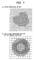
- Fig. 1 (a) shows a solid shape described using a conventional three-dimensional bit-map
- Fig. 1 (b) shows a solid shape described using the solid shape describing method of the present invention.
- Both solid shapes (a) and (b) are originated from the same solid body.
- some solid shapes are illustrated explanatorily as two-dimensional ones so as to make it easier to understand. Even in such cases, each actual body should be taken as a three-dimensional one.
- Fig. 1(a) shows a solid shape described using a conventional three-dimensional bit-map. This method defines a grid that divides a three-dimensional space into many voxels. Each voxel includes information that denotes its center exists inside or outside the subject solid shape. In Fig. (a) , each voxel, when about 50% or more of its capacity is inside the solid shape, is colored.
- Fig. 1(b) shows a solid shape described using the solid shape describing method of the present invention.
- the solid shape is originated from the same solid body as that shown in Fig. 1(a).
- This method uses a plurality of coordinate systems and a grid is defined for each of the coordinate systems. In this case, two coordinate systems are used; a coarse grid defined orthogonal coordinate system and a fine grid defined polar coordinate system.
- Fig. 2 shows a data structure of the solid shape data D described by the solid shape describing method of the present invention.
- the solid shape data D includes a fixed coordinate system DA, a floating coordinate system list DL, and a cell operation specifier DC.
- the solid shape data D may include any number of floating coordinate systems DF or may not any.
- Each of those coordinate systems may include a coordinate system parameter and a three-dimensional cell array respectively or may not any of them.
- the coordinate system parameter consists of three independent variables used to define a grid for dividing a three-dimensional space.
- the three-dimensional cell array is obtained by dividing a three-dimensional space by this grid.
- the fixed coordinate system DA may include a fixed coordinate system parameter DA1 and a fixed three-dimensional cell array DA2.
- the floating coordinate system DF may include a floating coordinate system parameter DF1 and a floating three-dimensional cell array DF2.
- Each cell includes information that denotes whether its center is inside or outside the subject solid shape.
- the floating coordinate system list DL is used for managing the floating coordinate system DF.
- Each coordinate system may include one element attribute or may not any.
- the element attribute defines such characteristics as the color, surface roughness, light reflection rate, and density of each cell included in a three-dimensional cell array or solid shape described with coordinate systems.
- a floating coordinate system DF includes a coordinate conversion function DF4 and a global/local ordinal DF5.
- the coordinate conversion function DF4 converts the floating coordinate parameter DF1 to a fixed coordinate parameter DA1. This conversion is described in the following format.
- X X (x, y, z)
- Y Y (x, y, z)
- Z Z (x, y, z)
- the (X, Y, Z) is a fixed coordinate parameter DA1 and the (x, y, z) is a floating coordinate parameter DF1.
- a solid shape specific to the subject coordinate system is determined uniquely.
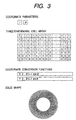
- Fig. 3 shows the relationship between them.
- one polar coordinate system is picked up as an example of the floating coordinate system DF.
- the distance from the origin and the rotation angle from'the Y axial direction are assumed as parameters r and ⁇ .
- Both of r and ⁇ are real numbers and have the following domains. 1 ⁇ r ⁇ 2 0 ⁇ 2 ⁇
- a three-dimensional cell array uses r and ⁇ as arguments.
- the array element is any of 0 and 1.
- a voxel determined by r and ⁇ exists outside the subject solid shape.
- the element is 1, the voxel exists inside the solid shape.
- the three-dimensional cell array shown here includes 8 elements in the r direction and 60 elements in the ⁇ direction. The top left element therefore corresponds to the following r and ⁇ values.
- the coordinate conversion function converts r and ⁇ that are coordinate parameters specific to this floating coordinate system DF to absolute coordinate parameters, that is, X and Y that are fixed coordinate parameters DA1. As a result, a point (X, Y) having an absolute position comes to correspond to an element of the subject three-dimensional cell array.
- the global/local ordinal DF5 denotes whether a floating coordinate system DF is a global or local one.
- the fixed coordinate system DA among a plurality of coordinate systems included in a solid shape data D is the widest range coordinate system.
- the global/local ordinal DF5 of the global floating coordinate system DF next to the fixed coordinate system DA is 1.
- the global/local ordinal DF5 increases as it goes closer to the local floating coordinate system DF.
- the global/local ordinal DF5 may be the same among a plurality of floating coordinate system DF.
- Whether a point exists inside or outside the subject solid shape is determined by the value of the three-dimensional cell array of the coordinate system that includes the point.
- the point is included in a plurality of coordinate systems, it is determined by the value of the three-dimensional cell array whose coordinate system has the largest value of the global/local ordinal DF5.
- the cell operation specifier DC which specifies how to process the values of those three-dimensional cell arrays in such a case, handles the values as follows.
- OR operation The values of a plurality of three-dimensional cell arrays are ORed. A point that is regarded to exist inside the subject solid shape in a coordinate system is regarded finally to exist inside the solid shape.
- AND operation The values of a plurality of three-dimensional cell arrays are ANDed. A point that is regarded to exist inside the subject solid shape in all the coordinate systems is regarded finally to exist inside the solid shape.
- MAJ operation Whether a point exists inside or outside the subject solid shape is determined by the number of coordinate systems that regard the point to exist "inside” or the number of coordinate systems that regard the point to exist "outside”, whichever is larger in number. When both coordinate system numbers are equal, a coordinate system with the smaller value of the global/local ordinal DF5 is referred for the decision.
- the solid shape data D can include a limitless number of floating coordinate systems DF, so that it is possible to lay the floating coordinate systems DF in layers using the global/local ordinal DF5 and the cell operation specifier DC to define a limitlessly finer grid, thereby making the jaggy size smaller than a given limit threshold value.
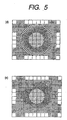
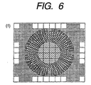
- Figs. 4 through 6 show changes of a solid shape described using the solid shape data D of the present invention to occur due to the changes of the global/local ordinal DF5 in a floating coordinate system DF.
- Fig. 4(a) shows a fixed coordinate system DA and Fig. 4(b) and (c) show two types of floating coordinate systems DF.
- Fig. 4(d) through (f) show solid shapes, each being formed by a combination of their coordinate systems on each of the following conditions.
- the solid shape changes.
- the global/local ordinal DF5 of each fine grid coordinate system should be set larger.
- the solid shape data D can have the following characteristics.
- the engineering system to be described below also uses the characteristics of the solid shape data D described by the solid shape describing method of the present invention.
- Fig. 7 shows a block diagram of a remote solid machining apparatus SA in the first embodiment of the present invention.
- the system SA includes a three-dimensional CAD apparatus S1 and a three-dimensional machining apparatus S2 that are connected to each other through a communication line S33.
- the three-dimensional CAD apparatus S1 includes a shape processor S1 a data storage unit S12, a display unit S13, an operator console S14, and an external interface S15.
- the shape processor S11 may be a personal computer or work station provided with a CPU, a memory, and programs and data stored in the memory.
- the shape processor S11 when receiving a command D2 from the operator console S14, executes the corresponding processing, such as creation, modification, correction, and comparison of the solid shape data D stored in the data storage unit S12, as well as such processing as changes of the data structure and inputs/outputs of data.
- the data storage unit S12 may be a magnetic disk or semiconductor memory and used to store solid shape data D described by the solid shape describing method of the present invention.
- the display unit S13 may be a CRT display or liquid crystal display. It displays solid shape data D and other design information as the display image D1.
- the operator console S14 includes a mouse and a keyboard.
- the console S14 when receiving an input from the operator, sends the corresponding command D2 to the shape processor S11.
- the external interface S15 may be a LAN board or network adapter. It receives B-reps data D3 from another unit connected to the remote solid machining system SA.
- Fig. 8 shows a flowchart of the remote solid body machining process PA for manufacturing a product MA using the B-reps data D3 using the remote solid machining apparatus SA.
- the remote solid body machining process PA includes a B-reps data preparation process P1, a B-reps data conversion process P2, a data transmission process P3, a control code creation process P4, and an NC machining process P5.
- the B-reps data preparing process P1 prepares B-reps data D3 used by a conventional general three-dimensional CAD. Another system provided with such a three-dimensional CAD apparatus is used to create B-reps data D3, then transfer the data D3 to the remote solid machining apparatus SA through the external interface S15. This is a practical method.
- the B-reps data conversion process P2 describes a solid shape described with the B-reps data D3 using the solid shape describing method of the present invention so as to convert the B-reps data D3 to solid shape data D.
- the solid shape describing method of the present invention is effective to reduce the data size through this conversion, since the data size is the same.
- the data transmission process P3 transmits solid shape data D from the three-dimensional CAD apparatus S1 to the three-dimensional machining apparatus S2 through the communication line S33.
- the control code creation process P4 creates control codes D4 for the NM machine S24 according to the solid shape data D. So-called G codes may be used as those control codes D4.
- the NC machining process P5 controls the NC machine S24 according to the control code D4 to manufacture the product MA.
- Fig. 9 shows the detailed B-reps data conversion process P2, which converts B-reps data D3 to solid shape data D.
- the B-reps data conversion process P2 includes a fixed coordinate system determination process P21, a floating coordinate system creation process P22, a floating coordinate system disposition process P23, and a three-dimensional cell array determination process P24.
- the fixed coordinate system determination process P21 determines a fixed coordinate system DA. In other words, the process P21 determines an origin and a reference coordinate axis to determine a fixed coordinate parameter DA1.
- Ordinary B-reps data D3 includes the definitions of both origin and coordinate axis, so that they can be used as they are.
- the floating coordinate system creation process P22 creates new floating coordinate systems DF.
- the operator inputs a command D2 through the operator console S14.
- the floating three-dimensional cell array DF2 and the coordinate conversion function DF4 among them are determined in the floating coordinate system disposition process P23 and the three-dimensional cell array determination process P24, so that the operations up to the input of the floating coordinate parameter DF1 are executed in the floating coordinate system creation process P22.
- the floating coordinate system disposition process P23 determines the disposition of each floating coordinate system DF. Namely, the process P23 determines the coordinate conversion function DF4 for each floating coordinate system DF.
- Fig. 10 shows a screen of the display unit S13 for disposing a floating coordinate system DF. On the screen, a control point of a floating coordinate system DF is displayed together with B-reps data D3. The operator specifies the control point (an origin, end point, or the like) of a target coordinate system using the mouse and/or inputs the control point coordinates to dispose the floating coordinate system DF.
- the three-dimensional cell array determination process P24 determines whether each voxel defined by the grid of a floating coordinate system DF exists inside or outside the subject solid shape described with the B-reps data D3, then substitutes a value for each element of the floating three-dimensional cell array DF2. Consequently, all of the floating coordinate parameter DF1, the floating three-dimensional cell array DF2, and the coordinate conversion function DF4 of the subject floating coordinate system DF are determined. Namely, the floating coordinate system DF comes to describe the subject solid shape.
- the operator may be able to check the coordinate systems included in the solid shape data D and display the coordinate systems in the order of the global/local ordinals DF5, that is, beginning at the widest range coordinate system. This method makes it possible for the operator to know the target solid shape roughly before receiving the whole solid shape.
- Fig. 11 shows a screen of the display unit S13 for displaying some solid shape data D using the above described method for displaying coordinate systems sequentially, beginning at the widest ranged one. The more the operator receives the solid shape data D, the more the solid shape is displayed in detail.
- the data structure of the solid shape data D is advantageous even when a solid body is cut out by the NC machine S24 according to the data D.
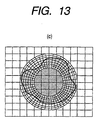
- Figs. 12 and 13 show a machining procedure for a solid body using the NC machine S24 according to the solid shape data D.
- each element shape is described by a thick line and the target product MA shape is colored.
- Fig. 12(a) shows an element that is not machined yet.
- a tool as an end mill is used to shave off an element portion whose solid shape is determined by the fixed coordinate system DA, that is, the element portion that is not included in the target solid shape, where no floating coordinate system DF is disposed.
- the portion is equivalent to a voxel in which the element value of the fixed three-dimensional cell array DA2 is 0.
- This machining proceeds along the outer periphery of the floating coordinate system DF defined by a rough grid of the fixed coordinate system DA and a coordinate conversion function DF4. Consequently, a large diameter tool can be used to shorten the machining time.
- the element is thus machined into the shape shown in Fig. 12(b).
- the tool is replaced with a small diameter one to machine the element according to the floating coordinate system DF whose global/local ordinal DF5 is smaller next to that of the fixed coordinate system DA.
- the element is thus machined into the shape as shown in Fig. 13(c).
- the tool is replaced with a further smaller diameter one to machine the element more finely when another floating coordinate system DF with a larger global/local ordinal DF5 is disposed.
- Fig. 14 shows a block diagram of a solid shape CAD/CAM system SB in the second embodiment of the present invention.
- the solid shape CAD/CAM system SB includes a three-dimensional CAD apparatus 1, an optical fabrication unit S4, and an X-ray CT unit S5.
- the optical fabrication unit S4 and the X-ray CT unit S5 are connected to the three-dimensional CAD apparatus S1 respectively.
- the three-dimensional CAD apparatus S1 is the same as that in the first embodiment.
- the optical fabrication unit S4 when receiving a modeling data D4 described by the solid shape describing method of the present invention from the three-dimensional CAD apparatus S1, manufactures a real body having the solid shape with resin, etc.
- the optical fabrication technique which is an operation principle of the optical modeling unit S4, refer to "Laminated Modeling System (Takeo Nakagawa, Yoji Marutani/KOGYO CHOSAKAI PUBLISHING CO., LTD.).
- the X-ray CT unit S5 takes cross-sectional views of respective real bodies by shifting the cross-section little by little. Many cross-sectional views taken such way can be combined to obtain a real body solid shape.
- the solid shape is then described by the solid shape describing method of the present invention as measured data D6, which are then sent to the three-dimensional CAD apparatus S1.
- measured data D6 which are then sent to the three-dimensional CAD apparatus S1.
- the X-ray CT technique which is an operation principle of the X-ray CT unit S5 refer to "Non-contact Measurement/Recognition Technical Data Book" (Optoronics co., ltd.).
- Fig. 15 shows a flowchart of the solid shape designing process, which is the second embodiment of the present invention.
- B-reps data preparation process P1 includes a B-reps data preparation process P1, a B-reps data conversion process P2, a model manufacturing process P6, a model evaluation process P7, a model correction process P8, an original shape data correction process P9, a model measurement process P10, and a measured data reflection process P11.
- the B-reps data preparation process P1 is the same as that in the first embodiment.
- the B-reps data conversion process P2 is also the same as that in the first embodiment.
- the model manufacturing process P6 uses the optical fabrication unit S4 to manufacture the model MB having a solid shape described according to the original shape data D5.
- the accuracy for manufacturing the model MB can be set at 0.1mm or under when a high accurate optical fabrication unit that uses epoxy resin is used.
- the model evaluation process P7 can evaluate the shape of the model MB through visual and tactual senses of the evaluator by holding, coloring, and lighting the model MB or to make mechanical performance tests for the usage of the model MB.
- the model correction process P8 machines the model MB to correct the solid shape.
- the evaluator evaluates the shape of the model MB.
- the shape of the model MB is corrected by applying putty on and/or sticking another part to the MB. This correction is done more quickly and accurately than a method for correcting the solid shape data D, since it is done directly on the model MB.
- the model MB is returned to the model evaluation process P7 to be evaluated again.
- the operations in those processes are repeated until the model MB shape is optimized and finally the evaluator is satisfied.
- the original shape data correction process P9 sends a command D2 to the shape processor S11 to correct the solid shape described with the original shape data D5.
- Fig. 16 shows details of the original shape data correction process P9 for correcting a solid shape described with the original shape data D5 to obtain a target solid shape.
- the process P9 includes a three-dimensional cell array change process P91 and a coordinate system change process P92.
- the model measurement process P10 uses the X-ray CT unit S5 to measure the shape of the model M and create measured data D6.
- the shape of the model M can be measured at an accurate of 0.1mm using an industrial X-ray CT unit that employs a high energy X-ray.
- the measured data reflection process P11 compares the measured data D6 with the original shape data D5 so as to reflect the corrected solid shape on the original shape data D5.
- the most simple form of reflection is to assume the measured data D6 as the original shape data D5.
- part of the original shape data D5 is replaced with the corresponding measured data D6.
- the difference between them is displayed on the screen. The method is also effective.
- CAD modeling and actual body modeling can be employed selectively in accordance with the characteristics of the object body using the solid shape CAD/CAM system SB. Consequently, both of the design efficiency and the design quality can be improved.
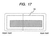
- Fig. 17 shows the original shape data D5 of the railway vehicle described by the solid shape describing method of the present invention.
- These original shape data D5 are created as a simple rectangular body using a three-dimensional CAD apparatus.
- each floating coordinate system DF is defined so that its grid has a higher resolution than that of the fixed coordinate system DA. Then, a floating coordinate system DF is disposed at the front portion to be deformed delicately due to the sense of the designer, as well as at the rear outer periphery respectively where the cross sectional shape must be determined accurately. The designer then defines each coordinate system grid and disposes it manually while checking it on the screen of the display unit S13.
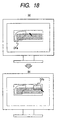
- Fig. 18 shows such a screen of the display unit S13 for disposing a floating coordinate system DF using the mouse.
- the screen displays the original shape data D5 through volume rendering.
- the designer then creates some more new floating coordinate systems DF and specifies each control point (the origin, end points, etc.) with the mouse cursor and inputs its coordinates to dispose the coordinate system.
- the three-dimensional CAD apparatus S1 is provided with a function for supporting the definition of each coordinate system. Generally, the more a solid shape is corrected finely, the more the surface element is reduced in size. When there are a plurality of solid shapes, the subject surface position is varied more at a frequently corrected portion. The three-dimensional CAD apparatus S1 makes most use of this to automatically find each finely corrected portion and/or portion to be corrected frequently and disposes a high resolution grid around the portion. The designer can also correct the disposition of the automatically disposed grid manually as described above.
- This original shape data D5 includes not only the fixed coordinate system DA, but also two floating coordinate systems DF that are a front portion coordinate system DFa and a rear portion coordinate system DFb.
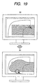
- Fig. 19 shows a screen of the display unit S13, displayed for correcting the original shape data D5 using the method.
- a virtual ball-like describing tool is dragged with the mouse to correct the solid shape.
- the three-dimensional cell array of the front portion coordinate system DFa is modified.
- the modification is reflected automatically in another coordinate system having a global/local ordinal DF5 smaller than that of the above three-dimensional cell array of the front portion coordinate system DFa.
- Another method is used to define the grid of each coordinate system and change the disposition of the coordinate system. This method enables such operations as parallel movement, rotational movement, symmetrical movement, expansion, compaction, and copying to be made accurately.
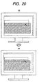
- Fig. 20 shows a screen of the display unit S13, displayed for correcting the original shape data D5 using this method.
- the rear portion cross sectional coordinate system DFb is dragged by the mouse cursor to correct the target solid shape.
- the modification is reflected automatically in another coordinate system having a smaller global/local ordinal DF5.
- This method when used to make a local correction, comes to be different from that in the first embodiment; the coordinate systems must be displayed in the descending order of global/local ordinals DF5, beginning from the widest range one. Namely, a local coordinate system is displayed first. According to this method, the whole original shape data D5 is not displayed each time the operator corrects the shape. The modification result of the shape is thus displayed immediately on the screen, thereby the local correction is done quickly.
- the original shape data D5 can have an element attribute.
- the designer can input and operate the fixed coordinate system element attribute DA3/floating coordinate system element attribute DF3 through the three-dimensional CAD apparatus S1.
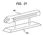
- Fig. 21 shows the shape of the model MB.
- the model MB is provided with a foot part MB1 that makes it easy to position the model MB to be attached to the X-ray CT unit S5.
- the designer then performs a wind-tunnel test for the model MB to evaluate the aerodynamic characteristics of the model MB.
- a railway vehicle when running at a high speed, generates a turbulence and this turbulence causes noise.
- the air resistance of the model MB must be minimized.
- the designer when recognizing an occurrence of a turbulence and/or an excessively large air resistance by the wind-tunnel test, can correct the shape by shaving the model MB partially and/or apply some putty on it.
- the direct correction of the real body by an experienced designer in wind-tunnel tests can often be done more quickly and accurately than the correction of the original shape data D5 by the three-dimensional CAD apparatus S1.
- the designer After the evaluation of the aerodynamic characteristics, the designer evaluates the external appearance of the model MB from every direction by coloring and checking the model MB. At this time, the designer can make the evaluation more accurately by intuition using the real body model MB than the evaluation of the external appearance only by checking the original shape data D5 on the screen of the display unit S13. If any thing is not satisfied with the model MB, the designer can shape the model MB again by shaving and/or applying some putty on it. If the shape is changed significantly, another aerodynamic test should be performed.
- the designer sets the model MB in the X-ray CT unit S5 to measure the solid shape.
- the designer sends a command to the three-dimensional CAD apparatus S1 and the original shape data D5 of the model MB to the X-ray CT unit S5.
- the original shape data D5 includes a plurality of coordinate systems, each having a resolution different from others, so that the X-ray CT unit S5 can select proper cross section intervals to be photographed in accordance with each of the coordinate systems. The measurement time can thus be saved.
- the designer can also obtain the measured data D6 having the same data structure as that of the original shape data D5 by processing each cross-sectional image obtained in accordance with the data structure of the original shape data D5.
- the attribute is copied to the measured data D6, thereby the designer can omit the input of the element attribute of the measured data D6.
- the measured data D6 can be used as new original shape data D5. It is also possible to compare data D6 with the data D5 to correct the original shape data D5.
- the rear part of the front portion keeps the same cross sectional shape, which is a so-called extruded shape.
- the measured data D6 of the model MB that rear part' cannot always be given the extruded shape due to an error to occur in the measurement even when no other portion except for the front portion is transformed.
- the original shape data D5 is used partially or the measured data D6 must be corrected strictly into the target extruded shape.
- railway vehicles are symmetrical in shape at most of their portions. However, the symmetry might not be kept strictly in manual deformation of the model MB. To secure the symmetry strictly, the solid shape described with the measured data D6 is divided into symmetrical two parts, then the average value must be calculated by measuring how much each of the parts is deformed. According to the method of the present invention, it is easy to divide a solid shape into symmetrical two parts by copying both of the coordinate system DFa of the front portion and the coordinate system DFb of the rear cross-sectional portion, then turning them over at the center plane, then adding the result to the measured data D6.
- the solid shape describing method of the present invention is very effective to make it easy to do the operations.
- the method is also effective for machining products using an NC cutting machine, although the above example of the railway vehicle is not suitable for an example of the following case.
- the cutting is done only at a portion defined by a floating coordinate system, so that other portions can be cut quickly using a large cutter. Namely, the cutting and machining time can be reduced significantly.
- the solid shape CAD/CAM system S which is provided with an optical fabrication unit S4 and an X-ray CT unit S5, those components are not always required. Those components can be replaced with others having similar functions.
- the optical fabrication unit S4 can be replaced with such a rapid prototyping unit as an SLS modeling unit/LOM modeling unit/FDM modeling unit.
- the unit S4 can also be replaced with a 3/5-axis NC machine. Those units may also be used to create a wax pattern to cast a vanishing model.
- a rapid prototyping unit that can paint shaped articles will make it possible to create models MB painted automatically using the fixed coordinate system element attribute DA3 and the floating coordinate system element attribute DF3.
- the element attributes will make it possible to use only a specific element portion for creating a model MB.
- the X-ray CT unit S5 may be replaced with an optical cutting type measuring unit and/or a probe type measuring unit. A plurality of measuring methods may also be combined.
- a photographic measuring unit makes it possible to reflect any painted color of the model MB on the fixed coordinate system element attribute DA3/floating coordinate system element attribute DF3.
- the present invention it is possible to provide a solid shape describing method that enables shape data to include feature-related information and the shape data to be reduced in size while features of the subject three-dimensional bit-map are kept as are, as well as to provide an engineering system that employs the method.
- the features of the three-dimensional bit-map are, for example, that the same data is always assumed for the same shape, the data structure is kept at a slight deformation, the data size is prevented from a limitless increase even for a complicated shape.
Landscapes
- Physics & Mathematics (AREA)
- Engineering & Computer Science (AREA)
- Geometry (AREA)
- Computer Graphics (AREA)
- Software Systems (AREA)
- General Physics & Mathematics (AREA)
- Theoretical Computer Science (AREA)
- Processing Or Creating Images (AREA)
- Numerical Control (AREA)
Abstract
Disclosed is a solid shape describing apparatus provided
with a function for defining both absolute coordinate system
and floating coordinate system, a function for describing a
relationship between the absolute coordinate system and the
floating coordinate system, a function for defining a
three-dimensional cell array, a function for describing the
correspondence between the floating coordinate system and the
three-dimensional cell array, and a function for converting
the three-dimensional cell array to a solid model.
Description
The present invention relates to a method and an
apparatus for describing solid shapes and a CAD/CAM system
which employs the method. More particularly, the present
invention relates to a method and an apparatus for describing
solid shapes preferred to describe, operate, and send free
solid shapes, as well as a CAD/CAM system that employs the
method.
There are many well-known solid shape data items used
to describe solid shapes. "Solid model" and "surface model"
among them are used most frequently. The "solid model" means
solid shape data structured so that, when a solid body and a
point are given, which of the inside, outside, and surface of
the solid body includes the point can be determined by a certain
procedure. On the other hand, the "surface model" does not
have the data structure. A three-dimensional CAD/CAM system
usually employs the "solid model", since the system must
determine the mutual interference of solid bodies quickly.
For example, the official gazettes of JP-A H8-335279 and JP-A
H11-27273 disclose the methods for creating such solid
models.
There are also some more well-known methods for creating
solid models. The boundary representations (B-reps) is one
of those methods. According to this method, vertices, edges,
faces and solids are defined algebraically and the mutual
topologies are defined so as to describe the target solid shape.
The Constructive Solid Geometry (CSG) combines primitives,
which are basic elements of a solid shape, thereby describing
a complicated solid shape. A three-dimensional bit-map
describes a solid shape by defining a grid in a
three-dimensional space and it is defined which of the inside,
outside, and surface of the three-dimensional space includes
each of the areas (cells) divided by the grid.
Each of the above-described methods have merits and
defects. Especially, the features of the three-dimensional
map are different from those of the B-reps and the CSG. The
merits and defects of those methods are as shown below.
The merits of both B-reps and CSG against the
three-dimensional bit-map are as follows.
The merits of the three-dimensional bit-map against both
of B-reps and CSG are as follows:
The defects of both B-reps and CSG against the
three-dimensional bit-map are as follows:
The defects of the 3-dimensional bit-map against both
B-reps and CSG are as follows:
For how to describe a solid model and the features of each
of the methods, refer to the documents as "Computer Graphics"
(J.D. Foley, A.Dam, S.K.Feiner, J.F.Hughes/Addition-Wesley
Inc.), etc.
In any of the conventional 3-dimensional CAD systems,
B-reps and CSG have been used for solid models. In recent years,
however, the merits of the three-dimensional bit-map come to
be recognized once again now that the computer performance has
been improved significantly, free shape processing have become
easier, free from designing has become possible, designs are
of great account, and reverse engineering that creates solid
shape data by measuring natural things and existing products
has become wide-spread. Using such 3-dimensional bit-maps for
designing a solid shape, therefore, enables a comparison to
be made among a plurality of shapes, optimize a shape by
repeating slight deformation for it, and record a real body
as data through 3-dimensional measurements without requiring
any special technique.
While a 3-dimensional bit-map has the above described
(a to d) defects, the defects b and d are almost solved by the
rapid progress of the computer processing ability. The
defects a and c, however, have still remained as unsolved
problems.
A data compression technique may be used to reduce the
data size. Complicated data compression by the LZ method or
the like, however, should be avoided, since the whole subject
solid model data must be extended each time it is used. This
makes it difficult to use the solid model. This is why there
has been no choice for data compression but using a
comparatively simple and partial data compression method such
as the oct-tree method. Improvement of the compression rate
has been difficult so far.
To provide a solid shape with feature-related
information, for example, geometrical characteristics, as
well as meaning, machining method, and accuracy of the solid
shape, a method for adding solid shape data described using
the B-reps and CSG methods to the subject solid shape has been
used sometimes. This method, however, increases the data size
and almost lose the merits e, f, and g of the 3-dimensional
bit-map.
Any of the above conventional techniques, therefore,
have not so effective to solve the defects of the 3-dimensional
bit-map while the merits thereof are kept as are.
Under such circumstances, it is an object of the present
invention to provide a solid shape describing method for
describing solid models, which can reduce the solid shape data
size and make each solid shape data include feature-related
information while the merits of the three-dimensional bit-map,
as well as an engineering system which employs the method. The
above-described features of the three-dimensional bit-map are,
for example, that the same data is always assumed for the same
shape, the same data structure is kept at slight deformation,
the data size is prevented from limitless increasing even for
a complicated model.
The above object of the present invention can be achieved
by providing the method with a function for defining both an
absolute coordinate system and a floating coordinate system,
a function for describing a relationship between the absolute
coordinate system and the floating coordinate system, a
function for defining a 3-dimensional cell array, a function
for describing the correspondence between the floating
coordinate system and the 3-dimensional cell array, and a
function for converting the 3-dimensional cell array to a solid
model.
Firstly, the present invention is characterized by a
method or apparatus for describing a solid model existing in
a 3-dimensional space with use of a bit-map, in which it is
defined that a coarse grid coordinate system and a fine grid
coordinate system are used and an area occupied by the fine
grid coordinate system and part or whole of an area occupied
by the coarse grid coordinate system are laid in layers.
Secondly, the present invention is characterized by a
method or apparatus for describing a solid model existing in
a 3-dimensional space, in which a fixed coordinate system is
defined with respect to the 3-dimensional space, a single or
a plurality of floating coordinate systems are defined, a
relative positional relationship of each of the floating
coordinate systems with the fixed coordinate system is
described algebraically, a single or plurality of
3-dimensional cell arrays are defined, and the correspondence
between the respective floating coordinate systems and the
respective 3-dimensional cell arrays is described.
According to the present invention, therefore, it is
possible to reduce the data size of a 3-dimensional bit-map
and include feature-related information in the solid shape
data while the merits of the three-dimensional bit-map data
are kept as are.
Still another feature of the present invention is a
remote solid body machining method or apparatus for
transmitting solid shape data through a communication line to
manufacture a real body according to the shape data; the shape
data is described by the above solid shape describing method.
According to this feature, it is possible to provide a
remote solid machining system that can reduce the transmission
time of complicated three-dimensional CAD data.
Still another feature of the present invention is a solid
shape data comparing method for making a comparison among a
plurality of solid shape data items, which includes a data
converting process for converting one of the plural of solid
shape data items to a solid model described by the above solid
shape describing method.
According to this feature, it is possible to make a
comparison among a plurality of three-dimensional CAD data
items using a small capacity of storage.
Still another feature of the present invention is a solid
shape describing method that includes a floating coordinate
system order defining function for defining an order among the
plural of floating coordinate systems.
According to this feature, it is possible to determine
whether a point exists inside or outside of the subject solid
shape even when a plurality of coordinate systems are laid in
layers and a voxel has different values for the same point.
Still another feature of the present invention is a solid
shape displaying method that includes a function for
displaying the external or cross-sectional view of a solid
model described using the above solid shape describing method.
The method obtains a priority level of each three-dimensional
cell array by evaluating whether the array represents a global
shape or local range shape of the solid model to display
three-dimensional'cell arrays in the order of their priority
levels.
Still another feature of the present invention is a solid
shape transmitting method that includes a function for
transmitting the above solid model through a communication
line, in which a priority level is determined for each of the
plural of three-dimensional cell arrays by evaluating whether
the array represents a global or local range shape of the solid
model so that the three-dimensional cell arrays are
transmitted in the order of their priority levels.
According to those methods, it is possible to display
or transmit whole or marked part of a solid shape quickly.
Still another feature of the present invention is a solid
shape data converting method for converting solid shape data
to a solid model described using the above solid shape
describing method, in which each of the plural of floating
coordinate systems is defined according to the surface
roughness, surface position deviation, surface element size,
or surface curvature radius included in the solid shape data.
According to this feature, it is possible to convert
three-dimensional CAD data to solid shape data described using
the solid shape describing method of the present invention
semi-automatically.
Still another feature of the present invention is an
element defining function included in the above solid shape
describing method, which can add an element characteristic
attribute to the floating coordinate system or a voxel
corresponding to the three-dimensional cell array.
According to this feature, it is possible to describe and
operate a colored solid and/or a solid composed of various
elements.
Still another feature of the present invention is a
detailed description availability defining function included
in the above solid shape describing method, which can add an
attribute to the floating coordinate system or a voxel
corresponding to the three-dimensional cell array, the
attribute denoting whether or not another floating coordinate
system describes the target solid shape more in detail.
According to this feature, it is possible to describe a
solid shape in limitless accuracy and compare a solid shape
with another in given accuracy.
Still another feature of the present invention is a
CAD/CAM system for solid shapes, which includes a solid
modeling unit for manufacturing a real body according to the
original shape data and a solid measuring unit for measuring
the real body. The CAD/CAM system corrects original shape data
according to the measured data obtained by the solid measuring
unit. The original data is described by the above solid shape
describing apparatus.
According to this feature, it is possible to provide a
CAD/CAM system for solid shapes, which can realize composite
modeling by feeding back the measured data to the modeling data.
Still another feature of the present invention is a
CAD/CAM system that includes a solid modeling unit for
manufacturing a real body according to the original data and
a solid measuring unit for measuring the real body. In the
CAD/CAM system, the solid measuring unit determines a
measuring procedure by referring to the original data
described by the above solid shape describing apparatus.
Still another feature of the present invention is a
function included in the solid measuring unit. The function
changes a measurement resolution according to a size of a voxel
included in the original data and corresponding to the
three-dimensional cell array in the above solid shape
describing apparatus.
According to those features, it is possible to provide
a high precision CAD/CAM system for solid shapes, which can
make measurement semi-automatically.
Still another feature of the present invention is a solid
shape editing unit provided with a function for creating or
changing the above solid model. The editing unit further
includes displaying means for displaying the solid model and
a function for displaying the above floating coordinate system
and the solid model in layers.
According to this feature, it is possible to provide a
solid shape editing unit that can convert three-dimensional
CAD data to the solid shape data described using the solid shape
describing method of the present invention.
Still another feature of the present invention is a solid
shape editing method for displaying or transmitting the above
solid model and selecting a method for determining the above
priority level for the three-dimensional cell array from any
of the following two methods; one of the methods sets a higher
priority level for a global three-dimensional cell array and
the other sets a higher priority level for a local
three-dimensional cell array.
According to this feature, it is possible to provide a
solid shape editing unit that can operate both of a solid shape
in a wide range and a solid shape in a local range properly.
Still another feature of the present invention is a method
employed by the machining unit in the above remote solid
machining system. The method of the machining unit determines
whether to refer to another floating coordinate system that
describes the shape data more in detail according to the
resolution of a machining tool.
According to this feature, it is possible to provide a
remote solid machining system that can save the machining time
while the required accuracy is assured.
Still another feature of the present invention is a
function for selecting part or whole of measured data and a
function for copying a selected portion of the measured data
to the original shape data. The functions are included in the
above CAD/CAM apparatus for solid shapes.
According to this feature, it is possible to provide a
CAD/CAM apparatus for solid shapes, which can realize perfect
reverse engineering by using measured data as modeling data.
Still another feature of the present invention is a medium
for storing the above solid model.
According to this feature, it is possible to
move/distribute the solid shape data described using the solid
shape describing method of the present invention.
While there are some engineering systems to be picked
up as an embodiment of the present invention, all the effects
of those engineering systems are obtained as a result of using
the solid shape describing method of the present invention.
It would thus appropriate to describe the solid shape
describing method of the present invention here in prior to
the description of those engineering systems.
At first, Fig. 1 (a) shows a solid shape described using
a conventional three-dimensional bit-map and Fig. 1 (b) shows
a solid shape described using the solid shape describing method
of the present invention. Both solid shapes (a) and (b) are
originated from the same solid body. In the following
description, some solid shapes are illustrated explanatorily
as two-dimensional ones so as to make it easier to understand.
Even in such cases, each actual body should be taken as a
three-dimensional one.
As described above, Fig. 1(a) shows a solid shape
described using a conventional three-dimensional bit-map.
This method defines a grid that divides a three-dimensional
space into many voxels. Each voxel includes information that
denotes its center exists inside or outside the subject solid
shape. In Fig. (a) , each voxel, when about 50% or more of its
capacity is inside the solid shape, is colored.
This method generates steps referred to as "jaggy" on
the surface of the described solid shape. To reduce the
"jaggy", the grid must be divided more finely. When the grid
is divided more finely, however, the number of voxels increases,
thereby the data size increases significantly. This is a
substantial defect of the three-dimensional bit-map.
On the other hand, Fig. 1(b) shows a solid shape described
using the solid shape describing method of the present
invention. The solid shape is originated from the same solid
body as that shown in Fig. 1(a). This method uses a plurality
of coordinate systems and a grid is defined for each of the
coordinate systems. In this case, two coordinate systems are
used; a coarse grid defined orthogonal coordinate system and
a fine grid defined polar coordinate system.
According to the solid shape describing method of the
present invention as described above, therefore, it is
possible to make each surface grid of a solid shape finer while
each inside rough grid is kept as is, thereby the "jaggy" is
reduced while the data size is suppressed from increasing.
Fig. 2 shows a data structure of the solid shape data D
described by the solid shape describing method of the present
invention.
The solid shape data D includes a fixed coordinate system
DA, a floating coordinate system list DL, and a cell operation
specifier DC. The solid shape data D may include any number
of floating coordinate systems DF or may not any.
Each of those coordinate systems may include a coordinate
system parameter and a three-dimensional cell array
respectively or may not any of them. The coordinate system
parameter consists of three independent variables used to
define a grid for dividing a three-dimensional space. The
three-dimensional cell array is obtained by dividing a
three-dimensional space by this grid. The fixed coordinate
system DA may include a fixed coordinate system parameter DA1
and a fixed three-dimensional cell array DA2. The floating
coordinate system DF may include a floating coordinate system
parameter DF1 and a floating three-dimensional cell array DF2.
Each cell includes information that denotes whether its center
is inside or outside the subject solid shape.
The floating coordinate system list DL is used for
managing the floating coordinate system DF. Each coordinate
system may include one element attribute or may not any. The
element attribute defines such characteristics as the color,
surface roughness, light reflection rate, and density of each
cell included in a three-dimensional cell array or solid shape
described with coordinate systems.
Unlike the fixed coordinate system DA, a floating
coordinate system DF includes a coordinate conversion function
DF4 and a global/local ordinal DF5. The coordinate conversion
function DF4 converts the floating coordinate parameter DF1
to a fixed coordinate parameter DA1. This conversion is
described in the following format.
X = X (x, y, z)
Y = Y (x, y, z)
Z = Z (x, y, z)
The (X, Y, Z) is a fixed coordinate parameter DA1 and the
(x, y, z) is a floating coordinate parameter DF1.
When a coordinate parameter/three-dimensional cell
array/coordinate conversion function is given, a solid shape
specific to the subject coordinate system is determined
uniquely. Fig. 3 shows the relationship between them. Here,
one polar coordinate system is picked up as an example of the
floating coordinate system DF. The distance from the origin
and the rotation angle from'the Y axial direction are assumed
as parameters r and . Both of r and are real numbers and
have the following domains.
1≦r≦2
0≦≦2π
A three-dimensional cell array uses r and as arguments.
The array element is any of 0 and 1. When the element is 0,
a voxel determined by r and exists outside the subject solid
shape. When the element is 1, the voxel exists inside the solid
shape. The three-dimensional cell array shown here includes
8 elements in the r direction and 60 elements in the direction.
The top left element therefore corresponds to the following
r and values.
r = 1+1/16 = 1.0625
= 0+2π/120 = π/60
When the number of elements in a three-dimensional cell
array increases such way, the grid becomes finer.
The coordinate conversion function converts r and that
are coordinate parameters specific to this floating coordinate
system DF to absolute coordinate parameters, that is, X and
Y that are fixed coordinate parameters DA1. As a result, a
point (X, Y) having an absolute position comes to correspond
to an element of the subject three-dimensional cell array.
The description will further continue with reference to
Fig. 2.
The global/local ordinal DF5 denotes whether a floating
coordinate system DF is a global or local one. Generally, the
fixed coordinate system DA among a plurality of coordinate
systems included in a solid shape data D is the widest range
coordinate system. The global/local ordinal DF5 of the global
floating coordinate system DF next to the fixed coordinate
system DA is 1. The global/local ordinal DF5 increases as it
goes closer to the local floating coordinate system DF. The
global/local ordinal DF5 may be the same among a plurality of
floating coordinate system DF.
Whether a point exists inside or outside the subject
solid shape is determined by the value of the three-dimensional
cell array of the coordinate system that includes the point.
When the point is included in a plurality of coordinate systems,
it is determined by the value of the three-dimensional cell
array whose coordinate system has the largest value of the
global/local ordinal DF5. When the global/local ordinal DF5
us the same among the plural of coordinate systems, the cell
operation specifier DC, which specifies how to process the
values of those three-dimensional cell arrays in such a case,
handles the values as follows.
OR operation: The values of a plurality of
three-dimensional cell arrays are ORed. A point that is
regarded to exist inside the subject solid shape in a coordinate
system is regarded finally to exist inside the solid shape.
AND operation: The values of a plurality of
three-dimensional cell arrays are ANDed. A point that is
regarded to exist inside the subject solid shape in all the
coordinate systems is regarded finally to exist inside the
solid shape.
MAJ operation: Whether a point exists inside or outside
the subject solid shape is determined by the number of
coordinate systems that regard the point to exist "inside" or
the number of coordinate systems that regard the point to exist
"outside", whichever is larger in number. When both
coordinate system numbers are equal, a coordinate system with
the smaller value of the global/local ordinal DF5 is referred
for the decision.
The solid shape data D can include a limitless number
of floating coordinate systems DF, so that it is possible to
lay the floating coordinate systems DF in layers using the
global/local ordinal DF5 and the cell operation specifier DC
to define a limitlessly finer grid, thereby making the jaggy
size smaller than a given limit threshold value.
Figs. 4 through 6 show changes of a solid shape described
using the solid shape data D of the present invention to occur
due to the changes of the global/local ordinal DF5 in a floating
coordinate system DF. Fig. 4(a) shows a fixed coordinate
system DA and Fig. 4(b) and (c) show two types of floating
coordinate systems DF.
While the global/local ordinal DF5 of the fixed
coordinate system DA is fixed at 0, any value can be specified
for that of each floating coordinate system DF.
Fig. 4(d) through (f) show solid shapes, each being formed
by a combination of their coordinate systems on each of the
following conditions.
global/local ordinal DF5 of (c) = 2
global/local ordinal DF5 of (c) = 1
global/local ordinal DF5 of (c) = 1
cell operation specifier DC = OR operation
Depending on which coordinate system three-dimensional
cell array value is used, the solid shape changes. When
consideration is taken for the reduction of jaggy, the
global/local ordinal DF5 of each fine grid coordinate system
should be set larger.
This completes the description of the data structure of
the solid shape data D. Because of the data structure, the
solid shape data D can have the following characteristics.
The engineering system to be described below also uses
the characteristics of the solid shape data D described by the
solid shape describing method of the present invention.
Fig. 7 shows a block diagram of a remote solid machining
apparatus SA in the first embodiment of the present invention.
The system SA includes a three-dimensional CAD apparatus S1
and a three-dimensional machining apparatus S2 that are
connected to each other through a communication line S33.
The three-dimensional CAD apparatus S1 includes a shape
processor S1 a data storage unit S12, a display unit S13,
an operator console S14, and an external interface S15.
The shape processor S11 may be a personal computer or work
station provided with a CPU, a memory, and programs and data
stored in the memory. The shape processor S11, when receiving
a command D2 from the operator console S14, executes the
corresponding processing, such as creation, modification,
correction, and comparison of the solid shape data D stored
in the data storage unit S12, as well as such processing as
changes of the data structure and inputs/outputs of data.
The data storage unit S12 may be a magnetic disk or
semiconductor memory and used to store solid shape data D
described by the solid shape describing method of the present
invention.
The display unit S13 may be a CRT display or liquid crystal
display. It displays solid shape data D and other design
information as the display image D1.
The operator console S14 includes a mouse and a keyboard.
The console S14, when receiving an input from the operator,
sends the corresponding command D2 to the shape processor S11.
The external interface S15 may be a LAN board or network
adapter. It receives B-reps data D3 from another unit
connected to the remote solid machining system SA.
Fig. 8 shows a flowchart of the remote solid body machining
process PA for manufacturing a product MA using the B-reps data
D3 using the remote solid machining apparatus SA. The remote
solid body machining process PA includes a B-reps data
preparation process P1, a B-reps data conversion process P2,
a data transmission process P3, a control code creation process
P4, and an NC machining process P5.
The B-reps data preparing process P1 prepares B-reps data
D3 used by a conventional general three-dimensional CAD.
Another system provided with such a three-dimensional CAD
apparatus is used to create B-reps data D3, then transfer the
data D3 to the remote solid machining apparatus SA through the
external interface S15. This is a practical method.
The B-reps data conversion process P2 describes a solid
shape described with the B-reps data D3 using the solid shape
describing method of the present invention so as to convert
the B-reps data D3 to solid shape data D. When B-reps data
D3 is used to describe a very complicated solid shape, the solid
shape describing method of the present invention is effective
to reduce the data size through this conversion, since the data
size is the same.
The data transmission process P3 transmits solid shape
data D from the three-dimensional CAD apparatus S1 to the
three-dimensional machining apparatus S2 through the
communication line S33.
The control code creation process P4 creates control
codes D4 for the NM machine S24 according to the solid shape
data D. So-called G codes may be used as those control codes
D4.
The NC machining process P5 controls the NC machine S24
according to the control code D4 to manufacture the product
MA.
Fig. 9 shows the detailed B-reps data conversion process
P2, which converts B-reps data D3 to solid shape data D. The
B-reps data conversion process P2 includes a fixed coordinate
system determination process P21, a floating coordinate system
creation process P22, a floating coordinate system disposition
process P23, and a three-dimensional cell array determination
process P24.
The fixed coordinate system determination process P21
determines a fixed coordinate system DA. In other words, the
process P21 determines an origin and a reference coordinate
axis to determine a fixed coordinate parameter DA1. Ordinary
B-reps data D3 includes the definitions of both origin and
coordinate axis, so that they can be used as they are.
The floating coordinate system creation process P22
creates new floating coordinate systems DF. When creating a
floating coordinate system DF for which none of the floating
coordinate parameter DF1, the floating three-dimensional cell
array DF2, and the coordinate conversion function DF4 is
determined yet, the operator inputs a command D2 through the
operator console S14. The floating three-dimensional cell
array DF2 and the coordinate conversion function DF4 among them
are determined in the floating coordinate system disposition
process P23 and the three-dimensional cell array determination
process P24, so that the operations up to the input of the
floating coordinate parameter DF1 are executed in the floating
coordinate system creation process P22.
The floating coordinate system disposition process P23
determines the disposition of each floating coordinate system
DF. Namely, the process P23 determines the coordinate
conversion function DF4 for each floating coordinate system
DF. Fig. 10 shows a screen of the display unit S13 for disposing
a floating coordinate system DF. On the screen, a control
point of a floating coordinate system DF is displayed together
with B-reps data D3. The operator specifies the control point
(an origin, end point, or the like) of a target coordinate
system using the mouse and/or inputs the control point
coordinates to dispose the floating coordinate system DF.
The three-dimensional cell array determination process
P24 determines whether each voxel defined by the grid of a
floating coordinate system DF exists inside or outside the
subject solid shape described with the B-reps data D3, then
substitutes a value for each element of the floating
three-dimensional cell array DF2. Consequently, all of the
floating coordinate parameter DF1, the floating
three-dimensional cell array DF2, and the coordinate
conversion function DF4 of the subject floating coordinate
system DF are determined. Namely, the floating coordinate
system DF comes to describe the subject solid shape.
When checking the solid shape data D received from the
three-dimensional CAD apparatus S1 through a comparatively
slow transfer rate communication line S33 on the display unit
S23 of the three-dimensional machining apparatus S2, the
operator may be able to check the coordinate systems included
in the solid shape data D and display the coordinate systems
in the order of the global/local ordinals DF5, that is,
beginning at the widest range coordinate system. This method
makes it possible for the operator to know the target solid
shape roughly before receiving the whole solid shape.
Fig. 11 shows a screen of the display unit S13 for
displaying some solid shape data D using the above described
method for displaying coordinate systems sequentially,
beginning at the widest ranged one. The more the operator
receives the solid shape data D, the more the solid shape is
displayed in detail.
The data structure of the solid shape data D is
advantageous even when a solid body is cut out by the NC machine
S24 according to the data D. Figs. 12 and 13 show a machining
procedure for a solid body using the NC machine S24 according
to the solid shape data D. In Figs. 12 and 13, each element
shape is described by a thick line and the target product MA
shape is colored.
Fig. 12(a) shows an element that is not machined yet.
At first, such a tool as an end mill is used to shave off an
element portion whose solid shape is determined by the fixed
coordinate system DA, that is, the element portion that is not
included in the target solid shape, where no floating
coordinate system DF is disposed. More concretely, the
portion is equivalent to a voxel in which the element value
of the fixed three-dimensional cell array DA2 is 0. This
machining proceeds along the outer periphery of the floating
coordinate system DF defined by a rough grid of the fixed
coordinate system DA and a coordinate conversion function DF4.
Consequently, a large diameter tool can be used to shorten the
machining time. The element is thus machined into the shape
shown in Fig. 12(b).
Then, the tool is replaced with a small diameter one to
machine the element according to the floating coordinate
system DF whose global/local ordinal DF5 is smaller next to
that of the fixed coordinate system DA. The element is thus
machined into the shape as shown in Fig. 13(c).
While the tools are changed just once to obtain the
expected shape of the product MA in this example, the tool is
replaced with a further smaller diameter one to machine the
element more finely when another floating coordinate system
DF with a larger global/local ordinal DF5 is disposed.
As described above, in a machining process of the solid
shape data D, different diameter tools can be selected and used
properly according to the grid fineness of the fixed coordinate
system DA and each floating coordinate system DF, so that the
machining can be made more accurately and quickly.
Fig. 14 shows a block diagram of a solid shape CAD/CAM
system SB in the second embodiment of the present invention.
The solid shape CAD/CAM system SB includes a three-dimensional
CAD apparatus 1, an optical fabrication unit S4, and an X-ray
CT unit S5. The optical fabrication unit S4 and the X-ray CT
unit S5 are connected to the three-dimensional CAD apparatus
S1 respectively.
The three-dimensional CAD apparatus S1 is the same as
that in the first embodiment.
The optical fabrication unit S4, when receiving a
modeling data D4 described by the solid shape describing method
of the present invention from the three-dimensional CAD
apparatus S1, manufactures a real body having the solid shape
with resin, etc. For the details of the optical fabrication
technique, which is an operation principle of the optical
modeling unit S4, refer to "Laminated Modeling System (Takeo
Nakagawa, Yoji Marutani/KOGYO CHOSAKAI PUBLISHING CO., LTD.).
The X-ray CT unit S5 takes cross-sectional views of
respective real bodies by shifting the cross-section little
by little. Many cross-sectional views taken such way can be
combined to obtain a real body solid shape. The solid shape
is then described by the solid shape describing method of the
present invention as measured data D6, which are then sent to
the three-dimensional CAD apparatus S1. For details of the
X-ray CT technique, which is an operation principle of the X-ray
CT unit S5, refer to "Non-contact Measurement/Recognition
Technical Data Book" (Optoronics co., ltd.).
Fig. 15 shows a flowchart of the solid shape designing
process, which is the second embodiment of the present
invention. According to this second embodiment, it is
possible to design any solid shapes from real body models MB
quickly and accurately using the solid shape CAD/CAM system
SB configured as described above. The solid shapes to be
designed in this embodiment are, for example, those difficult
to be designed only with a three-dimensional CAD apparatus,
more concretely, those to be evaluated/optimized in accordance
with sensitivity and those to be tested for
evaluation/optimization. To achieve the above effect, the
solid shape designing process PB shown in Fig. 15 includes a
B-reps data preparation process P1, a B-reps data conversion
process P2, a model manufacturing process P6, a model
evaluation process P7, a model correction process P8, an
original shape data correction process P9, a model measurement
process P10, and a measured data reflection process P11.
The B-reps data preparation process P1 is the same as
that in the first embodiment. The B-reps data conversion
process P2 is also the same as that in the first embodiment.
The model manufacturing process P6 uses the optical
fabrication unit S4 to manufacture the model MB having a solid
shape described according to the original shape data D5. The
accuracy for manufacturing the model MB can be set at 0.1mm
or under when a high accurate optical fabrication unit that
uses epoxy resin is used.
The model evaluation process P7 can evaluate the shape
of the model MB through visual and tactual senses of the
evaluator by holding, coloring, and lighting the model MB or
to make mechanical performance tests for the usage of the model
MB.
The model correction process P8 machines the model MB
to correct the solid shape. In the model evaluation process
P7, the evaluator evaluates the shape of the model MB. When
the model MB is not satisfied in the evaluation, the shape of
the model MB is corrected by applying putty on and/or sticking
another part to the MB. This correction is done more quickly
and accurately than a method for correcting the solid shape
data D, since it is done directly on the model MB.
After the correction of the model MB shape in the process
P8, the model MB is returned to the model evaluation process
P7 to be evaluated again. The operations in those processes
are repeated until the model MB shape is optimized and finally
the evaluator is satisfied.
The original shape data correction process P9 sends a
command D2 to the shape processor S11 to correct the solid shape
described with the original shape data D5.
Fig. 16 shows details of the original shape data
correction process P9 for correcting a solid shape described
with the original shape data D5 to obtain a target solid shape.
The process P9 includes a three-dimensional cell array change
process P91 and a coordinate system change process P92.
The model measurement process P10 uses the X-ray CT unit
S5 to measure the shape of the model M and create measured data
D6. The shape of the model M can be measured at an accurate
of 0.1mm using an industrial X-ray CT unit that employs a high
energy X-ray.
The measured data reflection process P11 compares the
measured data D6 with the original shape data D5 so as to reflect
the corrected solid shape on the original shape data D5. The
most simple form of reflection is to assume the measured data
D6 as the original shape data D5. When only part of a shape
is corrected, part of the original shape data D5 is replaced
with the corresponding measured data D6. In addition, when
the original shape data D5 and the measured data D6 are compared
with each other, the difference between them is displayed on
the screen. The method is also effective.
According to the solid shape CAD/CAM system SB as
described above, it is possible to link the "CAD modeling" with
the "actual body modeling" closely so as to realize the
"combined modeling" that employs the merits of both modeling
methods. The "CAD modeling" designs a virtual solid shape
using a three-dimensional CAD apparatus and the "actual body
modeling" designs a realistic solid shape using the real body.
CAD modeling merits:
Actual body modeling merits:
In other words, CAD modeling and actual body modeling
can be employed selectively in accordance with the
characteristics of the object body using the solid shape
CAD/CAM system SB. Consequently, both of the design
efficiency and the design quality can be improved.
Next, a description will be made for the effects to be
obtained by the solid shape CAD/CAM system SB of the present
invention for designing a shape of a railway vehicle as the
third embodiment of the present invention. Fig. 17 shows the
original shape data D5 of the railway vehicle described by the
solid shape describing method of the present invention. These
original shape data D5 are created as a simple rectangular body
using a three-dimensional CAD apparatus.
The following shapes must be determined in prior to the
designing of the railway vehicle.
Some coordinate systems are thus defined for the original
solid shape data D5. At first, each floating coordinate system
DF is defined so that its grid has a higher resolution than
that of the fixed coordinate system DA. Then, a floating
coordinate system DF is disposed at the front portion to be
deformed delicately due to the sense of the designer, as well
as at the rear outer periphery respectively where the cross
sectional shape must be determined accurately. The designer
then defines each coordinate system grid and disposes it
manually while checking it on the screen of the display unit
S13.
Fig. 18 shows such a screen of the display unit S13 for
disposing a floating coordinate system DF using the mouse. The
screen displays the original shape data D5 through volume
rendering. The designer then creates some more new floating
coordinate systems DF and specifies each control point (the
origin, end points, etc.) with the mouse cursor and inputs its
coordinates to dispose the coordinate system.
The three-dimensional CAD apparatus S1 is provided with
a function for supporting the definition of each coordinate
system. Generally, the more a solid shape is corrected finely,
the more the surface element is reduced in size. When there
are a plurality of solid shapes, the subject surface position
is varied more at a frequently corrected portion. The
three-dimensional CAD apparatus S1 makes most use of this to
automatically find each finely corrected portion and/or
portion to be corrected frequently and disposes a high
resolution grid around the portion. The designer can also
correct the disposition of the automatically disposed grid
manually as described above.
Then, the designer sends another command D2 to the
three-dimensional CAD apparatus S1. Thus, a fixed
three-dimensional cell array DA2 and a floating
three-dimensional cell array DF2 are created automatically
from the designed solid shape, thereby the original shape data
D5 described by the solid shape describing method of the present
invention is obtained. This original shape data D5 includes
not only the fixed coordinate system DA, but also two floating
coordinate systems DF that are a front portion coordinate
system DFa and a rear portion coordinate system DFb.
There are two methods for correcting the original shape
data D5 described by the solid shape describing method of the
present invention. One of the methods is used to describe a
three-dimensional shape and modifying the three-dimensional
cell array directly. The solid shape can thus be corrected
directly.
Fig. 19 shows a screen of the display unit S13, displayed
for correcting the original shape data D5 using the method.
In this example, a virtual ball-like describing tool is dragged
with the mouse to correct the solid shape. When a describing
operation is done, the three-dimensional cell array of the
front portion coordinate system DFa is modified. When the
operation ends, the modification is reflected automatically
in another coordinate system having a global/local ordinal DF5
smaller than that of the above three-dimensional cell array
of the front portion coordinate system DFa.
Another method is used to define the grid of each
coordinate system and change the disposition of the coordinate
system. This method enables such operations as parallel
movement, rotational movement, symmetrical movement,
expansion, compaction, and copying to be made accurately.
Fig. 20 shows a screen of the display unit S13, displayed
for correcting the original shape data D5 using this method.
In this example, the rear portion cross sectional coordinate
system DFb is dragged by the mouse cursor to correct the target
solid shape. In a move operation, at first the rear portion
coordinate system DFb is modified, then the modification is
reflected automatically in another coordinate system having
a smaller global/local ordinal DF5.
This method, when used to make a local correction, comes
to be different from that in the first embodiment; the
coordinate systems must be displayed in the descending order
of global/local ordinals DF5, beginning from the widest range
one. Namely, a local coordinate system is displayed first.
According to this method, the whole original shape data D5 is
not displayed each time the operator corrects the shape. The
modification result of the shape is thus displayed immediately
on the screen, thereby the local correction is done quickly.
The original shape data D5 can have an element attribute.
The designer can input and operate the fixed coordinate system
element attribute DA3/floating coordinate system element
attribute DF3 through the three-dimensional CAD apparatus S1.
The original shape data D5 created as described above is
sent to the optical modeling unit S4, thereby the model MB
having this solid shape is created automatically. Fig. 21
shows the shape of the model MB. The model MB is provided with
a foot part MB1 that makes it easy to position the model MB
to be attached to the X-ray CT unit S5.
The designer then performs a wind-tunnel test for the
model MB to evaluate the aerodynamic characteristics of the
model MB. A railway vehicle, when running at a high speed,
generates a turbulence and this turbulence causes noise. In
addition, to suppress the power consumption, the air
resistance of the model MB must be minimized. The designer,
when recognizing an occurrence of a turbulence and/or an
excessively large air resistance by the wind-tunnel test, can
correct the shape by shaving the model MB partially and/or apply
some putty on it. The direct correction of the real body by
an experienced designer in wind-tunnel tests can often be done
more quickly and accurately than the correction of the original
shape data D5 by the three-dimensional CAD apparatus S1.
After the evaluation of the aerodynamic characteristics,
the designer evaluates the external appearance of the model
MB from every direction by coloring and checking the model MB.
At this time, the designer can make the evaluation more
accurately by intuition using the real body model MB than the
evaluation of the external appearance only by checking the
original shape data D5 on the screen of the display unit S13.
If any thing is not satisfied with the model MB, the designer
can shape the model MB again by shaving and/or applying some
putty on it. If the shape is changed significantly, another
aerodynamic test should be performed.
When the solid shape is optimized after the evaluation
of both aerodynamic characteristics and external appearance
of the model MB, the designer sets the model MB in the X-ray
CT unit S5 to measure the solid shape. At this time, the
designer sends a command to the three-dimensional CAD
apparatus S1 and the original shape data D5 of the model MB
to the X-ray CT unit S5. The original shape data D5 includes
a plurality of coordinate systems, each having a resolution
different from others, so that the X-ray CT unit S5 can select
proper cross section intervals to be photographed in
accordance with each of the coordinate systems. The
measurement time can thus be saved. The designer can also
obtain the measured data D6 having the same data structure as
that of the original shape data D5 by processing each
cross-sectional image obtained in accordance with the data
structure of the original shape data D5. When the original
shape data D5 has an element attribute, the attribute is copied
to the measured data D6, thereby the designer can omit the input
of the element attribute of the measured data D6.
The measured data D6 can be used as new original shape
data D5. It is also possible to compare data D6 with the data
D5 to correct the original shape data D5.
For a railway vehicle, the rear part of the front portion
keeps the same cross sectional shape, which is a so-called
extruded shape. For the measured data D6 of the model MB, that
rear part' cannot always be given the extruded shape due to an
error to occur in the measurement even when no other portion
except for the front portion is transformed. To give that part
the extruded shape, therefore, the original shape data D5 is
used partially or the measured data D6 must be corrected
strictly into the target extruded shape. According to the
method of the present invention, it is easy to make such an
extruded shape strictly by obtaining one cross section, then
copying it to every cross-section by making good use of the
horizontal axis of the grid of the coordinate system DFb located
at the rear part cross section.
Railway vehicles are symmetrical in shape at most of
their portions. However, the symmetry might not be kept
strictly in manual deformation of the model MB. To secure the
symmetry strictly, the solid shape described with the measured
data D6 is divided into symmetrical two parts, then the average
value must be calculated by measuring how much each of the parts
is deformed. According to the method of the present invention,
it is easy to divide a solid shape into symmetrical two parts
by copying both of the coordinate system DFa of the front
portion and the coordinate system DFb of the rear
cross-sectional portion, then turning them over at the center
plane, then adding the result to the measured data D6.
When part of the measured data D6 is added to the original
shape data D5, part of the measured data D6 is duplicated and
used, the two measured data items D6 are compared, and the
average value of the two measured data items D6 is obtained,
therefore, the solid shape describing method of the present
invention is very effective to make it easy to do the
operations.
The method is also effective for machining products using
an NC cutting machine, although the above example of the railway
vehicle is not suitable for an example of the following case.
When a product must be cut using a small precision cutter, the
cutting is done only at a portion defined by a floating
coordinate system, so that other portions can be cut quickly
using a large cutter. Namely, the cutting and machining time
can be reduced significantly.
For the solid shape CAD/CAM system S, which is provided
with an optical fabrication unit S4 and an X-ray CT unit S5,
those components are not always required. Those components
can be replaced with others having similar functions. For
example, the optical fabrication unit S4 can be replaced with
such a rapid prototyping unit as an SLS modeling unit/LOM
modeling unit/FDM modeling unit. The unit S4 can also be
replaced with a 3/5-axis NC machine. Those units may also be
used to create a wax pattern to cast a vanishing model.
A rapid prototyping unit that can paint shaped articles
will make it possible to create models MB painted automatically
using the fixed coordinate system element attribute DA3 and
the floating coordinate system element attribute DF3. The
element attributes will make it possible to use only a specific
element portion for creating a model MB.
The X-ray CT unit S5 may be replaced with an optical
cutting type measuring unit and/or a probe type measuring unit.
A plurality of measuring methods may also be combined. A
photographic measuring unit makes it possible to reflect any
painted color of the model MB on the fixed coordinate system
element attribute DA3/floating coordinate system element
attribute DF3.
As described above, according to the present invention,
it is possible to provide a solid shape describing method that
enables shape data to include feature-related information and
the shape data to be reduced in size while features of the
subject three-dimensional bit-map are kept as are, as well as
to provide an engineering system that employs the method. The
features of the three-dimensional bit-map are, for example,
that the same data is always assumed for the same shape, the
data structure is kept at a slight deformation, the data size
is prevented from a limitless increase even for a complicated
shape.
Claims (22)
- A solid shape describing method for describing a solid model in a 3-dimensional space with use of a bit-map,
wherein a coarse grid coordinate system and a fine grid coordinate system are used, and
wherein it is defined so that an area occupied by said fine grid coordinate system and part or whole of an area occupied by said coarse grid coordinate system come to be laid in layers. - A solid shape describing method for describing a solid model in a 3-dimensional space, comprising the steps of:defining a fixed coordinate system with respect to said 3-dimensional space;defining a single or plurality of floating coordinate systems;describing a relative positional relationship algebraically between said respective floating coordinate systems and said fixed coordinate system;defining a single or plurality of three-dimensional cell arrays; anddescribing the correspondence between said respective floating coordinate systems and said respective three-dimensional cell arrays.
- A remote slid machining method for transmitting solid shape data through a communication line to manufacture a real body according to said shape data;
wherein said shape data is described using said solid shape describing method as described in claim 1 or 2. - A solid shape data comparing method for making a comparison among a plurality of solid shape data items,
wherein one of said plurality of solid shape data items is converted to a solid model described using said solid shape describing method as described in claim 1 or 2. - The method according to claim 2, further comprising a floating coordinate system order defining function for defining an order among said plurality of floating coordinate systems.
- A solid shape displaying method for displaying an external view or cross-sectional view of a solid model described using said solid shape describing method as described in claim 2, said method comprising the steps of:obtaining a priority level of each of said plurality of three-dimensional cell arrays by evaluating whether said array represents a global or local solid shape; anddisplaying said three-dimensional cell arrays in the order of their priority levels.
- A solid shape transmitting method for transmitting said solid model as described in claim 2 through a communication line, said method further comprising the steps of:obtaining a priority level of each of said plurality of three-dimensional cell arrays by evaluating whether said array represents a wide range or local shape of said solid model; andtransmitting said three-dimensional cell arrays in the order of their priority levels.
- A solid shape data converting method for converting solid shape data to a solid model described using said solid shape describing method as described in claim 2;
wherein each of said plurality of floating coordinate systems is defined according to the surface roughness, surface position variation, surface element size, or surface curvature radius included in said solid shape data with respect to a solid shape. - The method according to claim 2, further comprising an element defining function for enabling an attribute of element characteristics to be added to said floating coordinate system or a voxel corresponding to said three-dimensional cell array.
- The method according to claim 2, further comprising a detailed description availability defining function for adding an attribute denoting whether or not another floating system describes a target solid shape more in detail, to said floating coordinate system or a voxel corresponding to said three-dimensional cell array.
- A solid shape describing apparatus provided with a function for describing a solid model in a three-dimensional space using a bit-map,
wherein said apparatus is further provided with a coarse grid coordinate system and a fine grid coordinate system, and
wherein said apparatus is configured so that it is defined that an area occupied by said fine grid coordinate system and part or whole of an area occupied by said coarse grid coordinate system are laid in layers. - A solid shape describing apparatus provided with a function for describing a solid model in a three-dimensional space, said apparatus further comprising:a fixed coordinate system defining function for defining a fixed coordinate system with respect to said three-dimensional space;a floating coordinate system defining function for defining a single or plurality of floating coordinate systems;a fixed-floating coordinate system relative relationship describing function for describing a relative positional relationship algebraically between said respective floating coordinate systems and said fixed coordinate system;a three-dimensional cell array defining function for defining a single or plurality of three-dimensional cell arrays; anda floating coordinate system - three-dimensional cell array correspondence describing function for describing the correspondence between said respective floating coordinate systems and said respective three-dimensional cell arrays.
- A remote solid machining system for solid bodies, which includes transmitting means for transmitting shape data through a communication line and a machining unit for manufacturing a real product according to said shape data,
wherein said shape data is described using said solid shape describing apparatus as described in claim 11 or 12. - A CAD/CAM system for solid shapes, which includes a solid modeling unit for manufacturing a real body according to said original shape data and a solid measuring unit for measuring said real body,
wherein said original shape data is described using said solid shape describing apparatus as described in claim 11 or 12, and
wherein said original shape data is corrected according to the measured data obtained by said solid measuring unit. - The CAD/CAM system according to claim 14,
wherein said solid measuring unit is a CT unit. - A CAD/CAM system for solid shapes, which includes a solid modeling unit for manufacturing a real body according to its original shape data and a solid measuring unit for measuring said real body,
wherein said original shape data is described using said solid shape describing apparatus as described in claim 11 or 12,; and
wherein said solid measuring unit determines a measuring procedure by referring to said original shape data. - The CAD/CAM system according to claim 16,
wherein said solid measuring unit changes a measuring resolution to another according to the size of a voxel corresponding to said three-dimensional cell array as described in claim 12. - A solid shape editing unit provided with a function for creating or changing said solid model as described in claim 12, said unit further comprising:displaying means for displaying said solid model; anda function for displaying said floating coordinate system and said solid model in layers.
- A solid shape editing method for displaying or transmitting said solid model as described in claim 2,
wherein said method for determining a priority level for said three-dimensional cell array, as described in claim 10 or 11 system; and
wherein one of said methods is selected, one of said methods being used to set a higher priority level for said wide range three-dimensional cell array and the other being used to set a higher priority level for said narrow range three-dimensional cell array. - The system according to claim 13,
wherein said shape data is described using said CAD/CAM system for solid shapes, as described in claim 14, and
wherein said machining unit determines whether to refer to another floating coordinate system for describing a detailed solid shape according to the resolution of a machining tool. - The CAD/CAM system according to claim 14, further comprising:a function for selecting part or whole of said measured data; anda function for copying a selected part to said original shape data.
- A medium for storing said solid model as described in claim 11 or 12.
Applications Claiming Priority (1)
| Application Number | Priority Date | Filing Date | Title |
|---|---|---|---|
| PCT/JP2000/006366 WO2002023408A1 (en) | 2000-09-18 | 2000-09-18 | Solid shape describing method and device therefor and solid shape design support system using them |
Publications (2)
| Publication Number | Publication Date |
|---|---|
| EP1321866A1 true EP1321866A1 (en) | 2003-06-25 |
| EP1321866A4 EP1321866A4 (en) | 2007-01-10 |
Family
ID=11736465
Family Applications (1)
| Application Number | Title | Priority Date | Filing Date |
|---|---|---|---|
| EP00961067A Withdrawn EP1321866A4 (en) | 2000-09-18 | 2000-09-18 | METHOD FOR DESCRIBING FULL PROFILES AND ASSOCIATED DEVICE AND SYSTEM FOR ASSISTING THE DESIGN OF FULL PROFILES USING THEM |
Country Status (4)
| Country | Link |
|---|---|
| US (3) | US6982711B1 (en) |
| EP (1) | EP1321866A4 (en) |
| JP (1) | JP3512406B2 (en) |
| WO (1) | WO2002023408A1 (en) |
Cited By (1)
| Publication number | Priority date | Publication date | Assignee | Title |
|---|---|---|---|---|
| EP3404626A1 (en) * | 2017-05-15 | 2018-11-21 | Fuji Xerox Co., Ltd | Editing device for three-dimensional shape data, three-dimensional shape data editing program, and method for editing three-dimensional shape data |
Families Citing this family (38)
| Publication number | Priority date | Publication date | Assignee | Title |
|---|---|---|---|---|
| WO2003016031A1 (en) | 2001-08-16 | 2003-02-27 | Riken | Rapid prototyping method and device using v-cad data |
| WO2003048980A1 (en) | 2001-12-04 | 2003-06-12 | Riken | Method for converting 3-dimensional shape data into cell inner data and conversion program |
| JP3906444B2 (en) * | 2002-09-02 | 2007-04-18 | セイコーエプソン株式会社 | Composite drawing system, method, program, and recording medium |
| JP4381743B2 (en) | 2003-07-16 | 2009-12-09 | 独立行政法人理化学研究所 | Method and program for generating volume data from boundary representation data |
| US7545373B2 (en) | 2004-08-03 | 2009-06-09 | Nextpat Limited | Applications with integrated capture |
| DE102005024949A1 (en) * | 2005-05-31 | 2006-12-07 | Friedrich-Alexander-Universität Erlangen-Nürnberg | Volume data sets e.g. computer tomography volume data sets, structures representation method, involves determining color and opacity values of allocation instruction from position coordinates at one position |
| JP4783100B2 (en) | 2005-09-12 | 2011-09-28 | 独立行政法人理化学研究所 | Method of converting boundary data into in-cell shape data and its conversion program |
| DE102005050205A1 (en) * | 2005-10-20 | 2007-04-26 | Mtu Aero Engines Gmbh | Method and device for compensating position and shape deviations |
| DE102005050209A1 (en) * | 2005-10-20 | 2007-04-26 | Ott, Reinhold, Waterloo | Video signal feeding device for e.g. television set, has control unit for controlling video signal source depending on presence signal that is delivered by presence detect unit, which detects presence of person at area of feeding device |
| KR100753536B1 (en) * | 2006-05-04 | 2007-08-30 | 주식회사 아이너스기술 | Method to detect 2D sketch data from raw model data for 3D reverse engineering modeling |
| JP4904944B2 (en) * | 2006-06-30 | 2012-03-28 | 富士通株式会社 | CAM system and method |
| JP4616853B2 (en) * | 2007-03-12 | 2011-01-19 | 三菱重工業株式会社 | Model processing method and model processing system |
| US8285407B2 (en) * | 2007-10-25 | 2012-10-09 | The Boeing Company | Method and apparatus for composite part data extraction |
| US8442804B2 (en) * | 2007-10-25 | 2013-05-14 | The Boeing Company | Method and apparatus for composite part data extraction |
| US8253726B1 (en) | 2008-01-09 | 2012-08-28 | Spaceclaim Corporation, Inc. | Systems and methods for modifying three dimensional geometry using an arbitrary cross-section plane |
| JP2011048603A (en) * | 2009-08-27 | 2011-03-10 | Hitachi Ltd | Display device and display method |
| US8620627B2 (en) * | 2009-10-13 | 2013-12-31 | The Boeing Company | Composite information display for a part |
| EP2500688A1 (en) | 2009-11-10 | 2012-09-19 | Mitsubishi Heavy Industries, Ltd. | Workpiece measuring device, collision preventing device, and machine tool |
| US8993084B2 (en) | 2010-08-17 | 2015-03-31 | The Boeing Company | Multi-layer metallic structure and composite-to-metal joint methods |
| US9522512B2 (en) | 2010-08-17 | 2016-12-20 | The Boeing Company | Methods for making composite structures having composite-to-metal joints |
| US8652606B2 (en) | 2010-08-17 | 2014-02-18 | The Boeing Company | Composite structures having composite-to-metal joints and method for making the same |
| CA2817507C (en) | 2012-12-10 | 2021-08-03 | Dirtt Environmental Solutions, Ltd. | Efficient lighting effects in design software |
| CA2838197C (en) | 2013-01-25 | 2020-05-12 | Robert W. Blodgett | Real-time depth of field effects with design software |
| SG11201605971WA (en) | 2013-01-31 | 2016-09-29 | Dirtt Environmental Solutions | Method and system for efficient modeling of specular reflection |
| SG11201605982WA (en) | 2013-01-31 | 2016-08-30 | Dirtt Environmental Solutions | Visual distortion effects through translucent structures in design software |
| US9569564B2 (en) * | 2013-02-11 | 2017-02-14 | Ford Global Technologies, Llc | Automated cad process for creating mold packages |
| CN103279608B (en) * | 2013-05-28 | 2015-12-02 | 南京航空航天大学 | The fast finding localization method of large complicated part process operation |
| EP2956873A4 (en) | 2013-05-31 | 2016-11-02 | Ice Edge Business Solutions Ltd | ASSOCIATION OF COMPUTER-EXECUTIVE OBJECTS IN THREE-DIMENSIONAL SPACES IN AN ARCHITECTURAL DESIGN ENVIRONMENT |
| US9528287B2 (en) | 2013-06-10 | 2016-12-27 | Dirtt Environmental Solutions, Ltd. | Angled wall connection devices, systems, and methods |
| US10922450B2 (en) | 2014-06-09 | 2021-02-16 | Dirtt Environmental Solutions, Ltd. | Associating computer-executable objects with timber frames within an architectural design environment |
| CN104385590B (en) * | 2014-10-10 | 2017-06-13 | 合肥斯科尔智能科技有限公司 | A kind of method that 3 D-printing system carries out product self-inspection |
| JP6252651B1 (en) | 2016-10-19 | 2017-12-27 | 富士ゼロックス株式会社 | 3D shape data editing device, 3D shape data editing program, and 3D shape data structure |
| JP6969149B2 (en) * | 2017-05-10 | 2021-11-24 | 富士フイルムビジネスイノベーション株式会社 | 3D shape data editing device and 3D shape data editing program |
| US10733710B2 (en) * | 2017-12-19 | 2020-08-04 | Microsoft Technology Licensing, Llc | System and method for drawing beautification |
| US11806948B2 (en) | 2019-12-12 | 2023-11-07 | The Boeing Company | Method of forming flyaway stringer end caps |
| US11718047B2 (en) | 2019-12-12 | 2023-08-08 | The Boeing Company | Flyaway stringer end caps |
| CN111415411B (en) * | 2020-03-02 | 2023-12-12 | 重庆市勘测院 | Space coordinate correcting and encrypting method for three-dimensional model |
| CN117916738A (en) | 2022-04-12 | 2024-04-19 | 三菱重工业株式会社 | Model generation device, model generation system, model generation method and program |
Family Cites Families (14)
| Publication number | Priority date | Publication date | Assignee | Title |
|---|---|---|---|---|
| US4334124A (en) * | 1980-03-26 | 1982-06-08 | Intergraph Corporation | Floating coordinate system |
| JP3080728B2 (en) | 1991-10-29 | 2000-08-28 | 日本電気株式会社 | Synthesis method of molecular part coordinates |
| JPH05197785A (en) | 1992-01-20 | 1993-08-06 | Nippon Telegr & Teleph Corp <Ntt> | Method for description processing of object shape |
| US5365996A (en) * | 1992-06-10 | 1994-11-22 | Amei Technologies Inc. | Method and apparatus for making customized fixation devices |
| JP2637920B2 (en) * | 1994-08-11 | 1997-08-06 | インターナショナル・ビジネス・マシーンズ・コーポレイション | Computer graphic system and method of using frame buffer |
| JPH09237354A (en) | 1996-02-29 | 1997-09-09 | Chokosoku Network Computer Gijutsu Kenkyusho:Kk | Method for transferring and displaying three-dimensional shape data |
| US5831621A (en) * | 1996-10-21 | 1998-11-03 | The Trustees Of The University Of Pennyslvania | Positional space solution to the next best view problem |
| US6278457B1 (en) * | 1998-01-15 | 2001-08-21 | International Business Machines Corporation | Methods and apparatus for performing sampling based synthesis of three-dimensional geometric models |
| US6889374B1 (en) * | 1998-10-23 | 2005-05-03 | Autodesk, Inc. | Using context prefixes that correspond to user input modes to control execution of scripting language |
| JP2000182081A (en) * | 1998-12-14 | 2000-06-30 | Suzuki Motor Corp | Analysis model creation method and apparatus, and storage medium storing analysis model creation program or analysis model data |
| JP2000235409A (en) | 1998-12-14 | 2000-08-29 | Cec:Kk | Method of creating machining program in NC device |
| JP3854033B2 (en) * | 2000-03-31 | 2006-12-06 | 株式会社東芝 | Mechanism simulation apparatus and mechanism simulation program |
| AU2003294327B2 (en) * | 2002-11-15 | 2010-04-01 | Sunfish Studio, Llc | Visible surface determination system and methodology in computer graphics using interval analysis |
| US6917369B2 (en) * | 2003-03-25 | 2005-07-12 | Mitsubishi Electric Research Labs, Inc. | Method and apparatus for rendering cell-based distance fields using texture mapping |
-
2000
- 2000-09-18 WO PCT/JP2000/006366 patent/WO2002023408A1/en not_active Ceased
- 2000-09-18 US US10/239,058 patent/US6982711B1/en not_active Expired - Fee Related
- 2000-09-18 EP EP00961067A patent/EP1321866A4/en not_active Withdrawn
- 2000-09-18 JP JP2002527985A patent/JP3512406B2/en not_active Expired - Fee Related
-
2004
- 2004-03-23 US US10/806,182 patent/US7468725B2/en not_active Expired - Fee Related
- 2004-03-23 US US10/806,112 patent/US7006087B2/en not_active Expired - Fee Related
Cited By (2)
| Publication number | Priority date | Publication date | Assignee | Title |
|---|---|---|---|---|
| EP3404626A1 (en) * | 2017-05-15 | 2018-11-21 | Fuji Xerox Co., Ltd | Editing device for three-dimensional shape data, three-dimensional shape data editing program, and method for editing three-dimensional shape data |
| US10672194B2 (en) | 2017-05-15 | 2020-06-02 | Fuji Xerox Co., Ltd. | Editing device for three-dimensional shape data, and non-transitory computer readable medium storing three-dimensional shape-data editing program |
Also Published As
| Publication number | Publication date |
|---|---|
| JPWO2002023408A1 (en) | 2004-01-22 |
| US6982711B1 (en) | 2006-01-03 |
| US20040174359A1 (en) | 2004-09-09 |
| US20040174358A1 (en) | 2004-09-09 |
| EP1321866A4 (en) | 2007-01-10 |
| US7006087B2 (en) | 2006-02-28 |
| JP3512406B2 (en) | 2004-03-29 |
| US7468725B2 (en) | 2008-12-23 |
| WO2002023408A1 (en) | 2002-03-21 |
Similar Documents
| Publication | Publication Date | Title |
|---|---|---|
| US7006087B2 (en) | Method and apparatus for describing solid shapes, and CAD/CAM system which employs the method | |
| Thompson et al. | Feature-based reverse engineering of mechanical parts | |
| US5003498A (en) | Graphic display method | |
| EP3082055B1 (en) | Rotorcraft component simulation using scan-based geometry | |
| Li et al. | Path planning method for on-machine inspection of aerospace structures based on adjacent feature graph | |
| Zheng et al. | A primitive-based 3D reconstruction method for remanufacturing | |
| Marsan et al. | An assessment of data requirements and data transfer formats for layered manufacturing | |
| Choi et al. | Visualisation of rapid prototyping | |
| EP1452984A1 (en) | Method for converting 3-dimensional shape data into cell inner data and conversion program | |
| Pal | An easy rapid prototyping technique with point cloud data | |
| Avrampos et al. | Coverage in planar surface polishing by trochoidal tool paths | |
| Štefan et al. | Reverse engineering in automotive design component | |
| JP3895297B2 (en) | Three-dimensional shape description method and engineering system using the same | |
| CN117786867A (en) | Fillet detection method, system, program, and storage medium | |
| Legge | Integration of design and inspection systems-a literature review | |
| JPH0821089B2 (en) | Solid model shape definition method in CAD / CAM system | |
| Veeramani et al. | Issues in patch-by-patch machining of compound sculptured surfaces | |
| Lee | Automatic planning and programming for five-axis sculptured surface machining | |
| Abrari | Multi-Axis milling of flexible parts | |
| US20250315564A1 (en) | Machine-learning in structural optimization | |
| US20250336176A1 (en) | Shell or offset feature detection in a 3d model representing a mechanical part | |
| EP4492274A1 (en) | Draft feature detection method | |
| JP2025165406A (en) | Profile detection in discrete 3D models representing machined parts | |
| Echevarrieta Ibarra et al. | Evolution-based tool path and motion planning optimization for 5-axis CNC machining of free-form surfaces | |
| Makki et al. | 5-axis direct machining of rough clouds of points |
Legal Events
| Date | Code | Title | Description |
|---|---|---|---|
| PUAI | Public reference made under article 153(3) epc to a published international application that has entered the european phase |
Free format text: ORIGINAL CODE: 0009012 |
|
| 17P | Request for examination filed |
Effective date: 20030408 |
|
| AK | Designated contracting states |
Designated state(s): AT BE CH CY DE DK ES FI FR GB GR IE IT LI LU MC NL PT SE |
|
| RBV | Designated contracting states (corrected) |
Designated state(s): DE |
|
| A4 | Supplementary search report drawn up and despatched |
Effective date: 20061212 |
|
| 17Q | First examination report despatched |
Effective date: 20081211 |
|
| STAA | Information on the status of an ep patent application or granted ep patent |
Free format text: STATUS: THE APPLICATION IS DEEMED TO BE WITHDRAWN |
|
| 18D | Application deemed to be withdrawn |
Effective date: 20090623 |