EP1321785A2 - Emi shielded adapter for fiber optic connector systems - Google Patents
Emi shielded adapter for fiber optic connector systems Download PDFInfo
- Publication number
- EP1321785A2 EP1321785A2 EP02258655A EP02258655A EP1321785A2 EP 1321785 A2 EP1321785 A2 EP 1321785A2 EP 02258655 A EP02258655 A EP 02258655A EP 02258655 A EP02258655 A EP 02258655A EP 1321785 A2 EP1321785 A2 EP 1321785A2
- Authority
- EP
- European Patent Office
- Prior art keywords
- adapter
- chassis
- set forth
- electrically
- wall
- Prior art date
- Legal status (The legal status is an assumption and is not a legal conclusion. Google has not performed a legal analysis and makes no representation as to the accuracy of the status listed.)
- Ceased
Links
Images

Classifications
-
- G—PHYSICS
- G02—OPTICS
- G02B—OPTICAL ELEMENTS, SYSTEMS OR APPARATUS
- G02B6/00—Light guides; Structural details of arrangements comprising light guides and other optical elements, e.g. couplings
- G02B6/24—Coupling light guides
- G02B6/36—Mechanical coupling means
- G02B6/38—Mechanical coupling means having fibre to fibre mating means
- G02B6/3807—Dismountable connectors, i.e. comprising plugs
- G02B6/381—Dismountable connectors, i.e. comprising plugs of the ferrule type, e.g. fibre ends embedded in ferrules, connecting a pair of fibres
-
- G—PHYSICS
- G02—OPTICS
- G02B—OPTICAL ELEMENTS, SYSTEMS OR APPARATUS
- G02B6/00—Light guides; Structural details of arrangements comprising light guides and other optical elements, e.g. couplings
- G02B6/24—Coupling light guides
- G02B6/36—Mechanical coupling means
- G02B6/38—Mechanical coupling means having fibre to fibre mating means
- G02B6/3807—Dismountable connectors, i.e. comprising plugs
- G02B6/381—Dismountable connectors, i.e. comprising plugs of the ferrule type, e.g. fibre ends embedded in ferrules, connecting a pair of fibres
- G02B6/3825—Dismountable connectors, i.e. comprising plugs of the ferrule type, e.g. fibre ends embedded in ferrules, connecting a pair of fibres with an intermediate part, e.g. adapter, receptacle, linking two plugs
-
- G—PHYSICS
- G02—OPTICS
- G02B—OPTICAL ELEMENTS, SYSTEMS OR APPARATUS
- G02B6/00—Light guides; Structural details of arrangements comprising light guides and other optical elements, e.g. couplings
- G02B6/24—Coupling light guides
- G02B6/36—Mechanical coupling means
- G02B6/38—Mechanical coupling means having fibre to fibre mating means
- G02B6/3807—Dismountable connectors, i.e. comprising plugs
- G02B6/3897—Connectors fixed to housings, casing, frames or circuit boards
Definitions
- the present invention relates generally to adapters for the use with fiber optics, and, more specifically, to an adapter having electromagnetic interference (EMI) shielding.
- EMI electromagnetic interference
- an adapter refers to any structure that facilitates fiber/fiber, device/fiber and device/device interconnections.
- the plug typically comprises a plug housing and a ferrule or other means for holding and precisely positioning one or more fiber ends.
- adapters include, for example, connector couplings which facilitate the connection of two plugs. Such couplings may have various configurations (e.g., simplex, duplex and quad) for use in various applications (e.g., backplane and through-chassis interconnections).
- Another important type of adapter includes those that are attached to or integral with a device to facilitate the optical connection between the device and a plug.
- Typical devices include, for example, active devices, such as transceivers and transmitters, and passive devices, such as attenuators and multiplexers/demultiplexers.
- adapters are used to facilitate the connection of an optical connector plug to another connector plug or device contained within a chassis.
- chassis as used herein broadly refers to a containment structure for housing electrical components or switching components.
- the connector assembly is typically mounted in a chassis or housing through an opening which is slightly larger than the housing of the adapter.
- the adapter is attached to the chassis using fasteners which extend through mounting holes in the tabs which extend from either side of the adapter. Although effective in securing an adapter to a chassis, this mounting configuration may be susceptible to EMI leakage.
- EMI EMI
- other electronic equipment used in conjunction with optical components may be sensitive to EMI noise or may generate EMI noise.
- the chassis be designed to prevent passage of EMI radiation.
- adapter openings in the chassis are sources of EMI leakage.
- the MU adapter requires an opening of approximately 5/8" by 3/8".
- a chassis will typically have a series of openings to accommodate a multitude of adapters thus compounding the EMI leakage problem.
- One common prior art approach for providing EMI shielding around adapters is to cover the connector assembly with an electrically-conductive shroud or boot. Although this provides reduced EMI leakage, it requires space within the chassis to accommodate the EMI boot. This is problematic since space within the chassis is usually limited. Furthermore, as the complexity of equipment increases to accommodate more fibers, space within the chassis will become even more precious.
- the present invention fulfills this need among others.
- the adapter comprises: (a) an elongated housing having a first and second end and defining a first passageway extending axially from the first end toward the second end, and a second passageway extending axially from the second end toward the first end, each passageway configured to receive an optical connector plug; (b) an electrically-conductive wall traversing the adapter between the first and second passageways, the wall being sized to cover a substantial portion of the opening when the adapter is mounted to the chassis; and (c) at least one portion of the wall extending outside of the housing to electrically couple with the chassis of the computer system when the adapter is mounted to the chassis forming an electrically-conductive path between a point on the wall and the chassis.
- this portion extends around the entire perimeter of the adapter resulting in a continuous or nearly continuous ring of contact when the adapter is mounted to the chassis. Having an electrical coupling around the perimeter increases the EMI shielding performance of the adapter by reducing areas of possible leakage and ensures the shortest possible path to ground from any point on the electrically-conductive wall.
- the adapter in accordance with the present invention provides several advantages over the prior art. First, it reduces EMI leakage in and out of the shielded chassis through the hole where the adapter is mounted. This is accomplished without the need for a space consuming EMI boot inside the chassis. Additionally, it forms an electrical coupling with the chassis along a substantial portion of the perimeter of its surface that contacts the chassis faceplate. This minimizes the grounding path length for any point on the electrically-conductive wall, thereby reducing the potential for the electrically-conductive wall to radiate EMI. Aside from offering improved EMI performance, the adapter of the present invention reduces assembly time and expense by eliminating the need to install an EMI boot over the installed adapter. The adapter of the present invention is installed using the same procedure and tools as a conventional adapter. Thus, the adapter of the present invention offers the benefits of a conventional adapter plus improved EMI shielding.
- the present invention provides for an adapter (as defined above) which comprises internally EMI shielding to reduce the EMI emissions passing in or out of a chassis on which the adapter is mounted.
- the adapter of the present invention is described herein with respect to shown in the figures and discussed in detail herein as applied to MU duplex adapter. It should be understood, however, that the present invention may be practiced with adapters of any known or later-developed connector systems, including, for example, the MPO connector system, Lightray MPX7 connector system (Tyco Electronics Corporation, Harrisburg, PA), LC connector system, SC connector system, FC connector system, and MT-RJ connector system.
- the present invention is discussed below using an MU connector system as the preferred embodiment.
- the invention is not limited to this connector type and is applicable to all connector systems utilizing an adapter portion.
- the adapter of the present invention is not restricted to facilitating plug to plug connections, but may be used to facilitate the interconnection of different devices or plugs and devices as discussed above with respect to the definition of adapter.
- an adapter of the present invention is shown which is suitable for receiving MU-type connector plugs and for mounting in an opening of a chassis of a computer system (not shown).
- the adapter comprises an elongated housing 11 having a first and second end 11a, 11b.
- the housing defines a first passageway 12a extending axially from the first end 11a toward the second end 11b, and a second passageway 12b extending axially from the second end 12b toward the first end 11a.
- Each passageway is configured to receive an optical connector plug which in this particular embodiment is an MU connector plug.
- the adapter also comprises an electrically-conductive wall 23 traversing the housing 11 between the first and the second passageways.
- the electrically-conductive wall 23 is sized to cover a substantial portion of the opening when the adapter is mounted to the chassis. At least one portion (e.g., 13, 17) of the wall extends beyond the housing to electrically couple with the chassis of the computer system when the adapter is mounted to the chassis thereby forming an electrically-conductive path between a point 26 on the wall and the chassis.
- Figure 3 illustrates an adapter for an MU duplex connector system. It should be understood, however, that the present invention is not limited to this embodiment, and could be used with various fiber optic adapters.
- the adapter housing 11 is a rectilinear structure.
- This particular adapter serves to secure connector plugs in place such that the ferrules contained within the connector plugs are properly aligned, both axially and radially as is well known in the art.
- the adapter also serves to secure the connector assembly to the chassis.
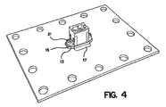
- Figure 4 illustrates an adapter that has been mounted to a faceplate.
- the adapter comprises mounting members 15 on two sides.
- a mounting hole 19 is located on each mounting member.
- the chassis faceplate typically has an opening which is large enough for the rectangular housing 11 of the adapter to be inserted into, but not large enough for the mounting members to pass through so that the mounting members contact the faceplate during installation.
- the opening size therefore, depends upon the particular type of adapter. For example, a typical opening size for an MU or MPO adapter is about 3/8" x 5/8".
- a fastener e.g., screw, rivet
- one side of the mounting member is in contact with the chassis or faceplate. This side is referred to herein as the contacting face 21, while the reverse side is the non-contacting face 22.
- each opening in a chassis faceplate is a potential leak for EMI emissions. As the number and size of these openings increases, the potential for EMI emissions increases.
- the adapter of the present invention employs an electrically-conductive shield to channel EMI emissions to ground. It is well known in the art that when an electromagnetic field passes over a grounded conductive member, a current is induced in the conductive member and the electromagnetic field is reduced. By creating an electrically-conductive shield across as much of the adapter opening as possible, EMI leakage can be minimized.
- the adapter of the present invention contains an electrically-conductive layer.
- the electrically-conductive layer in the preferred embodiment is a wall 23 formed from an electrically-conductive metal material.
- Figure 2 illustrates the electrically-conductive wall before it is incorporated into the adapter.
- the wall is located in the adapter to be approximately in the same plane as the chassis faceplate when the adapter is mounted to the faceplate. In the MU embodiment of the adapter, this position corresponds to about the midpoint between the first and second ends of the adapter.
- the electrically-conductive wall extends laterally across the adapter housing 11, as shown in Figure 3. and is perpendicularly aligned with the connector receiving passageways 12. The positioning of the electrically-conductive wall 23 within the adapter housing is such that when the adapter is mounted, the electrically-conductive wall 23 will extend across the opening in the chassis.
- the electrically-conductive wall 410 preferably spans the opening in the faceplate, some openings are necessary to accommodate the waveguide and perhaps the alignment features of the plug connector. For example, as illustrated in Figure 4, openings 403 and 403a are formed through the wall 23, each opening receives a ferrule containing a fiber.
- MT-type connector systems e.g., MPO connectors, Lightray MPX7 connectors
- the number and size of the openings in the electrically-conductive wall be kept to a minimum since increasing the size and the amount of openings in the wall will reduce the EMI shielding characteristics of the adapter.
- the amount of open area in the electrically-conductive wall will vary depending upon the type of connector used and whether it has alignment features that need to be accommodated.
- the adapter is configured to accommodate small form factor connectors, such as the MU, MPO, LC and Lightray MPX7 connector systems, since they have relatively small ferrules compared to older connector systems such as the SC and FC-type connectors.
- the connector system is a single-fiber ferrule type, such as the MU or LC connector systems, since single fiber, small form factors require the smallest openings in the electrically-conductive wall.
- the adapter When the adapter is mounted to the chassis of the faceplate, preferably at least 70% of the faceplate opening is blocked by the electrically-conductive wall, more preferably at least 80% of the opening is blocked, and even more preferably at least 90% of the opening is blocked.
- the electrically-conductive wall 23 can be formed using a variety of materials. Several factors contribute to the choice of material including high conductively, ease of manufacture, resiliency, and corrosion-resistence.
- the electrically-conductive wall in order to conduct the EMI to ground, the electrically-conductive wall must be a highly electrically-conductive material such as a metal or a polymeric embedded with metals.
- the electrically-conductive property of the electrically-conductive wall 23 may result in galvanic corrosion if not matched properly with the material of the chassis faceplate. Galvanic corrosion occurs when two dissimilar metals make electrical contact in the presence of an electrolyte, which can be moisture.
- the material used to form the electrically-conductive wall 23 should have properties closely matching the electrically-conductive surface to which it will be mounted.
- the electrically-conductive wall layer can be formed using a die cutting process. After the wall is die cut from a flat sheet, it needs to be formed into the adapter housing, which may require bending it around the mounting members 15 of the adapter (as described below), and it may have integral conducting members extending from it beyond the housing to make electric contact with the chassis when the adapter is mounted.
- an ideal material will be pliable enough to stamp and form and have enough resiliency to maintain its shape once formed but be able to deflect to accommodate tolerances in the adapter and between the adapter and the chassis faceplate.
- the electrically-conductive wall 23 in the preferred embodiment is formed using a phosphorous bronze alloy. This material provides adequate conductivity and corrosion properties, while at the same time, is easily configured using a stamping process.
- the electrically-conductive wall must be electrically coupled to the chassis when the adapter is mounted thereon.
- at least a portion of the electrically-conductive wall 23 extends beyond the interior of the housing of the adapter to contact the chassis faceplate and form an electrically-conductive coupling with it.
- the electrically-conductive wall comprises tabs 27 that extend from its edges. The tabs 27 are dimensioned to extend past the non-contacting side 27 of the mounting member, and to wrap around the edge 15a of the mounting member 15 such that a distal portion 13 covers at least a portion of the contacting surface 21.
- the electrically-conductive wall 23 extends over the front of the contacting surface 21 so that when the adapter is mounted to the chassis, electrical contact will be made between the distal portion 13 of the tab 27 and the chassis faceplate.
- electrical contact between the tabs and the chassis can be achieved by the pressure created between the contacting surface 21 and the chassis caused when a fastener 31 is employed to mount the adapter to the chassis faceplate.
- This method will provide effective electrical coupling between the chassis and the electrically-conductive wall, providing that the surface to which the adapter is mounted is smooth. If the chassis surface is not smooth or additional EMI protection is desired, additional EMI gasketing techniques may be used, including, for example, the use of electrically-conductive pliable gaskets, electrically-conductive adhesive, or electrically-conductive tape.
- the electrically-conductive wall also preferably comprises flanges 17 which extend outward on the sides of the adapter to create additional surface area for contacting the chassis.
- the two flanges 17 extend outward perpendicular to the adapter passageways 12 and run the entire length of the two longer sides of the rectangular adapter housing.
- flanges 17 contact the chassis when the adapter is mounted and thus increase the surface contact area.
- the flanges 17 are resilient and are formed such that they angle slightly in the direction of the contacting face 21. This way, when the flanges 17 are pressed against the chassis during mounting, they deflect resiliently and ensure physical contact the chassis as illustrated in Figure 4. This, in turn, insures electrical coupling between the electrically-conductive wall and the chassis and thereby reduces the possibility of EMI noise leakage through the termination interface.
- the combination of the tabs 27 and the resilient flanges 17 forms an electrically-conductive coupling around a substantial portion of the perimeter of the adapter which is in contact with the chassis. Having an electrically-conductive coupling around the perimeter increases the EMI shielding performance of the adapter by reducing areas of possible leakage and ensures the shortest possible path to ground from any point on the electrically-conductive wall 23. This is critical as the operating frequencies of the components inside the chassis increase. These components generate higher frequency EMI which can pass through even small openings or gaps. Much of the telecommunications equipment used today have components that operate at over 1 GHz and generate EMI at those frequencies and their higher order harmonics.
- the adapter of the present invention is configured to form an electrical coupling with the chassis along a substantial portion of the perimeter of its surface that contacts the chassis faceplate.
- the substantial portion is 80% of the perimeter, more preferably, the substantial portion is 90% of the perimeter. This minimizes the length of the grounding path for any point on the electrically-conductive surface, thereby reducing the potential for the electrically-conductive wall to radiate EMI.
- the term "grounding path length" refers to the shortest distance between a point on the electrically-conductive wall to a point along the perimeter of the adapter which conductively couples with the chassis when the adapter is installed.
- the grounding path length for any point on the electrically-conductive wall is no greater than the shortest cross-section dimension of the portion of the adapter which is inserted through the chassis opening (herein "short dimension").
- short dimension the shortest cross-section dimension of the portion of the adapter which is inserted through the chassis opening.
- the grounding path length for any point on the electrically-conductive wall would be no greater than 3/8".
- the grounding path length for any point on the electrically-conductive wall is no greater than half of the short dimension. In the example above, this translates to a grounding path length of no greater than 3/16".
Landscapes
- Physics & Mathematics (AREA)
- General Physics & Mathematics (AREA)
- Optics & Photonics (AREA)
- Details Of Connecting Devices For Male And Female Coupling (AREA)
Abstract
Description
Claims (17)
- An adapter for receiving optical connector plugs and being suitable for mounting through an opening in a chassis of a computer system, said adapter comprising:an elongated housing having a first and second end and defining a first passageway extending axially from said first end toward said second end, and a second passageway extending axially from said second end toward said first end, each passageway configured to receive an optical connector plug;an electrically-conductive wall traversing said adapter between said first and said second passageways, said wall being sized to cover a substantial portion of said opening when said adapter is mounted to said chassis; andat least one portion of said wall extending outside of said housing to electrically couple with the chassis of said computer system when said adapter is mounted to said chassis forming an electrically-conductive path between a point on said wall and said chassis.
- An adapter as set forth in claim 1, wherein said portion of said wall extending outside of said housing to electrically couple with the chassis of said computer system when said adapter is mounted to said chassis extends around the entire perimeter of said adapter resulting in a continuous ring of contact when said adapter is mounted to said chassis.
- An adapter as set forth in claim1, wherein said adapter has one or more flanges extending laterally outside of the adapter housing to facilitate said adapter=s connection to said chassis.
- An adapter as set forth in claim 1, wherein each flange has a contact face which abuts said chassis when said adapter is mounted to said chassis.
- An adapter as set forth in claim 1, wherein said wall comprises at least one orifice for allowing the passage of a ferrule of a connector.
- An adapter as set forth in claim 5, wherein said wall comprises at least one other orifice for allowing the passage of an alignment pin of said connector.
- An adapter as set forth in claim 5, wherein said ferrule is for an MU connector.
- An adapter as set forth in claim 5, wherein said ferrule is for an LC connector.
- An adapter as set forth in claim 5, wherein said ferrule is for an MPO connector.
- An adapter as set forth in claim 5, wherein said ferrule is for an Lightray MPX connector.
- An adapter as set forth in claim 5, wherein said ferrule is for an SC connector.
- An adapter as set forth in claim 5, wherein said ferrule is for an FC connector.
- An adapter as set forth in claim 5, wherein said wall is sized to cover at least about 75% of the opening.
- An adapter as set forth in claim 5, wherein said wall is sized to cover at least about 95% of the opening.
- An adapter as set forth in claim 1, wherein said electrically-conductive wall comprises a metal.
- An adapter as set forth in claim 1, wherein the grounding path length for any point on said electrically-conductive wall is no greater than the small dimension of said adapter.
- An adapter as set forth in claim 16, wherein the grounding path length is no greater than half the small dimension of said adapter.
Applications Claiming Priority (2)
| Application Number | Priority Date | Filing Date | Title |
|---|---|---|---|
| US34155601P | 2001-12-14 | 2001-12-14 | |
| US341556P | 2001-12-14 |
Publications (2)
| Publication Number | Publication Date |
|---|---|
| EP1321785A2 true EP1321785A2 (en) | 2003-06-25 |
| EP1321785A3 EP1321785A3 (en) | 2004-06-16 |
Family
ID=23338078
Family Applications (1)
| Application Number | Title | Priority Date | Filing Date |
|---|---|---|---|
| EP02258655A Ceased EP1321785A3 (en) | 2001-12-14 | 2002-12-16 | Emi shielded adapter for fiber optic connector systems |
Country Status (2)
| Country | Link |
|---|---|
| US (1) | US6891735B2 (en) |
| EP (1) | EP1321785A3 (en) |
Families Citing this family (22)
| Publication number | Priority date | Publication date | Assignee | Title |
|---|---|---|---|---|
| US7318751B2 (en) * | 2005-01-13 | 2008-01-15 | Tyco Electronics Corporation | Die-cast adapter |
| JP2008020740A (en) * | 2006-07-13 | 2008-01-31 | Fujitsu Component Ltd | Relay optical connector module |
| US7625137B2 (en) * | 2006-12-19 | 2009-12-01 | Finisar Corporation | Communications device |
| US7646615B2 (en) * | 2006-12-19 | 2010-01-12 | Finisar Corporation | Electromagnetic inferference shield for an optoelectronic module |
| US7845862B2 (en) * | 2006-12-19 | 2010-12-07 | Finisar Corporation | Communications device |
| US8104973B2 (en) * | 2007-02-09 | 2012-01-31 | Us Conec, Ltd. | Ferrule-to-ferrule adapter and ferrule adapter assembly |
| CN201285976Y (en) * | 2008-07-02 | 2009-08-05 | 富士康(昆山)电脑接插件有限公司 | Electric connector component |
| US9658409B2 (en) | 2015-03-03 | 2017-05-23 | Senko Advanced Components, Inc. | Optical fiber connector with changeable polarity |
| WO2017123460A1 (en) * | 2016-01-13 | 2017-07-20 | Ccs Technology, Inc. | Electromagnetic interference shielding adapter for coupling expanded beam optical connectors |
| US10158194B2 (en) | 2016-01-15 | 2018-12-18 | Senko Advanced Components, Inc. | Narrow width adapters and connectors with spring loaded remote release |
| US10295753B2 (en) * | 2016-01-28 | 2019-05-21 | Senko Advanced Components, Inc | Fiber optic hybrid adapter and connector assemblies |
| US9726830B1 (en) | 2016-06-28 | 2017-08-08 | Senko Advanced Components, Inc. | Connector and adapter system for two-fiber mechanical transfer type ferrule |
| US10228521B2 (en) | 2016-12-05 | 2019-03-12 | Senko Advanced Components, Inc. | Narrow width adapters and connectors with modular latching arm |
| US10185100B2 (en) * | 2017-01-30 | 2019-01-22 | Senko Advanced Components, Inc | Modular connector and adapter assembly using a removable anchor device |
| US10281669B2 (en) | 2017-07-14 | 2019-05-07 | Senko Advance Components, Inc. | Ultra-small form factor optical connectors |
| US11822133B2 (en) | 2017-07-14 | 2023-11-21 | Senko Advanced Components, Inc. | Ultra-small form factor optical connector and adapter |
| US12001064B2 (en) | 2017-07-14 | 2024-06-04 | Senko Advanced Components, Inc. | Small form factor fiber optic connector with multi-purpose boot |
| US10641972B2 (en) | 2017-08-17 | 2020-05-05 | Senko Advanced Components, Inc | Anti-jam alignment sleeve holder or connector housing for a ferrule assembly |
| US9972944B1 (en) | 2017-11-09 | 2018-05-15 | Te Connectivity Corporation | Pluggable module having a seam cover |
| WO2019194922A1 (en) | 2018-04-02 | 2019-10-10 | Senko Advanced Components, Inc | Hybrid ingress protected connector and adapter assembly |
| CN113631976B (en) | 2019-03-28 | 2023-06-09 | 扇港元器件有限公司 | Fiber optic adapter assembly |
| US20250189729A1 (en) * | 2023-12-06 | 2025-06-12 | Legrand DPC, LLC | Fiber Optic Adapter |
Family Cites Families (13)
| Publication number | Priority date | Publication date | Assignee | Title |
|---|---|---|---|---|
| US4618196A (en) * | 1985-05-30 | 1986-10-21 | Itt Corporation | Gender reversal connector |
| US5233674A (en) * | 1991-11-21 | 1993-08-03 | Methode Electronics, Inc. | Fiber optic connector with sliding tab release |
| US5886294A (en) | 1995-05-30 | 1999-03-23 | Scrimpshire; James Michael | Interference suppressing cable boot assembly |
| DE19530684C1 (en) * | 1995-08-08 | 1997-02-20 | Siemens Ag | Optical coupling device for laser diode or photodiode |
| US5937121A (en) * | 1997-01-03 | 1999-08-10 | The Siemon Company | Adapters for coupling optical fiber |
| JPH1123908A (en) * | 1997-06-27 | 1999-01-29 | New Japan Radio Co Ltd | Adapter for MT connector |
| US6085006A (en) * | 1997-09-12 | 2000-07-04 | International Business Machines Corporation | Optical fiber link module with internal electromagnetic shield |
| US6431764B1 (en) * | 1998-06-16 | 2002-08-13 | Stratos Lightwave | Optical transceiver RJ-jack with EMI shield |
| DE19905240C2 (en) | 1999-02-02 | 2001-12-06 | Infineon Technologies Ag | Coupling sleeve |
| US6193420B1 (en) * | 1999-08-13 | 2001-02-27 | Lucent Technologies Inc. | Shielded optical fiber adaptor |
| US6474876B1 (en) * | 1999-08-13 | 2002-11-05 | Fitel Usa Corp. | Shielded optical fiber adaptor |
| US6305961B1 (en) | 2000-07-12 | 2001-10-23 | Molex Incorporated | EMI gasket for connector assemblies |
| US6572272B2 (en) * | 2000-11-29 | 2003-06-03 | Berg Technology, Inc. | Angled optical connector mounting assembly |
-
2002
- 2002-12-16 EP EP02258655A patent/EP1321785A3/en not_active Ceased
- 2002-12-16 US US10/320,249 patent/US6891735B2/en not_active Expired - Lifetime
Also Published As
| Publication number | Publication date |
|---|---|
| US20030147230A1 (en) | 2003-08-07 |
| EP1321785A3 (en) | 2004-06-16 |
| US6891735B2 (en) | 2005-05-10 |
Similar Documents
| Publication | Publication Date | Title |
|---|---|---|
| US6891735B2 (en) | EMI shielded adapter for fiber optic connector systems | |
| US6607303B2 (en) | Angled optical connector mounting assembly | |
| EP1498754B1 (en) | Method of connecting two fibre optic cables with connectors | |
| US6193420B1 (en) | Shielded optical fiber adaptor | |
| US6220878B1 (en) | Optoelectronic module with grounding means | |
| US20050281509A1 (en) | Optical connector system with EMI shielding | |
| US6713672B1 (en) | Compliant shaped EMI shield | |
| US6822879B2 (en) | Embedded electromagnetic interference shield | |
| US7484896B2 (en) | Connector assembly with integrated electromagnetic shield | |
| EP1174959B1 (en) | EMI gasket for connector assemblies | |
| US6744639B1 (en) | Internal electromagnetic radiation shield with ground connection for removable small form factor transceivers | |
| US6474876B1 (en) | Shielded optical fiber adaptor | |
| EP1597618B1 (en) | Connector panel mount system | |
| CA2386313A1 (en) | Fiber optic adapter | |
| US11317547B2 (en) | Shielding housing for a detachable fully shielded internal cable assembly | |
| US20140147081A1 (en) | Connector systems having receptacle assembly and plug assembly | |
| US20020159712A1 (en) | EMI shield for fiber optic adapter | |
| JP2003121698A (en) | Optical connector shield structure | |
| EP1217402A2 (en) | Angled optical connector mounting assembly | |
| EP1725900B1 (en) | Optical connector | |
| JP3769178B2 (en) | Optical adapter | |
| JP2003270489A (en) | Optical connector adapter and optical connector plug | |
| US20260005480A1 (en) | Adapter for cable connection |
Legal Events
| Date | Code | Title | Description |
|---|---|---|---|
| PUAI | Public reference made under article 153(3) epc to a published international application that has entered the european phase |
Free format text: ORIGINAL CODE: 0009012 |
|
| AK | Designated contracting states |
Designated state(s): AT BE BG CH CY CZ DE DK EE ES FI FR GB GR IE IT LI LU MC NL PT SE SI SK TR |
|
| AX | Request for extension of the european patent |
Extension state: AL LT LV MK RO |
|
| PUAL | Search report despatched |
Free format text: ORIGINAL CODE: 0009013 |
|
| AK | Designated contracting states |
Kind code of ref document: A3 Designated state(s): AT BE BG CH CY CZ DE DK EE ES FI FR GB GR IE IT LI LU MC NL PT SE SI SK TR |
|
| AX | Request for extension of the european patent |
Extension state: AL LT LV MK RO |
|
| RIC1 | Information provided on ipc code assigned before grant |
Ipc: 7G 02B 6/42 B Ipc: 7G 02B 6/38 A |
|
| 17P | Request for examination filed |
Effective date: 20041216 |
|
| 17Q | First examination report despatched |
Effective date: 20050111 |
|
| AKX | Designation fees paid |
Designated state(s): AT BE BG CH CY CZ DE DK EE ES FI FR GB GR IE IT LI LU MC NL PT SE SI SK TR |
|
| STAA | Information on the status of an ep patent application or granted ep patent |
Free format text: STATUS: THE APPLICATION HAS BEEN REFUSED |
|
| 18R | Application refused |
Effective date: 20080327 |