EP1321729B1 - Refrigeration cycle and method for determining capacity of receiver thereof - Google Patents
Refrigeration cycle and method for determining capacity of receiver thereof Download PDFInfo
- Publication number
- EP1321729B1 EP1321729B1 EP02028338A EP02028338A EP1321729B1 EP 1321729 B1 EP1321729 B1 EP 1321729B1 EP 02028338 A EP02028338 A EP 02028338A EP 02028338 A EP02028338 A EP 02028338A EP 1321729 B1 EP1321729 B1 EP 1321729B1
- Authority
- EP
- European Patent Office
- Prior art keywords
- receiver
- condenser
- capacity
- refrigeration cycle
- refrigerant
- Prior art date
- Legal status (The legal status is an assumption and is not a legal conclusion. Google has not performed a legal analysis and makes no representation as to the accuracy of the status listed.)
- Revoked
Links
Images


Classifications
-
- F—MECHANICAL ENGINEERING; LIGHTING; HEATING; WEAPONS; BLASTING
- F25—REFRIGERATION OR COOLING; COMBINED HEATING AND REFRIGERATION SYSTEMS; HEAT PUMP SYSTEMS; MANUFACTURE OR STORAGE OF ICE; LIQUEFACTION SOLIDIFICATION OF GASES
- F25B—REFRIGERATION MACHINES, PLANTS OR SYSTEMS; COMBINED HEATING AND REFRIGERATION SYSTEMS; HEAT PUMP SYSTEMS
- F25B43/00—Arrangements for separating or purifying gases or liquids; Arrangements for vaporising the residuum of liquid refrigerant, e.g. by heat
-
- F—MECHANICAL ENGINEERING; LIGHTING; HEATING; WEAPONS; BLASTING
- F25—REFRIGERATION OR COOLING; COMBINED HEATING AND REFRIGERATION SYSTEMS; HEAT PUMP SYSTEMS; MANUFACTURE OR STORAGE OF ICE; LIQUEFACTION SOLIDIFICATION OF GASES
- F25B—REFRIGERATION MACHINES, PLANTS OR SYSTEMS; COMBINED HEATING AND REFRIGERATION SYSTEMS; HEAT PUMP SYSTEMS
- F25B39/00—Evaporators; Condensers
- F25B39/04—Condensers
-
- F—MECHANICAL ENGINEERING; LIGHTING; HEATING; WEAPONS; BLASTING
- F25—REFRIGERATION OR COOLING; COMBINED HEATING AND REFRIGERATION SYSTEMS; HEAT PUMP SYSTEMS; MANUFACTURE OR STORAGE OF ICE; LIQUEFACTION SOLIDIFICATION OF GASES
- F25B—REFRIGERATION MACHINES, PLANTS OR SYSTEMS; COMBINED HEATING AND REFRIGERATION SYSTEMS; HEAT PUMP SYSTEMS
- F25B2339/00—Details of evaporators; Details of condensers
- F25B2339/04—Details of condensers
- F25B2339/044—Condensers with an integrated receiver
- F25B2339/0441—Condensers with an integrated receiver containing a drier or a filter
-
- F—MECHANICAL ENGINEERING; LIGHTING; HEATING; WEAPONS; BLASTING
- F25—REFRIGERATION OR COOLING; COMBINED HEATING AND REFRIGERATION SYSTEMS; HEAT PUMP SYSTEMS; MANUFACTURE OR STORAGE OF ICE; LIQUEFACTION SOLIDIFICATION OF GASES
- F25B—REFRIGERATION MACHINES, PLANTS OR SYSTEMS; COMBINED HEATING AND REFRIGERATION SYSTEMS; HEAT PUMP SYSTEMS
- F25B2339/00—Details of evaporators; Details of condensers
- F25B2339/04—Details of condensers
- F25B2339/044—Condensers with an integrated receiver
- F25B2339/0446—Condensers with an integrated receiver characterised by the refrigerant tubes connecting the header of the condenser to the receiver; Inlet or outlet connections to receiver
-
- F—MECHANICAL ENGINEERING; LIGHTING; HEATING; WEAPONS; BLASTING
- F25—REFRIGERATION OR COOLING; COMBINED HEATING AND REFRIGERATION SYSTEMS; HEAT PUMP SYSTEMS; MANUFACTURE OR STORAGE OF ICE; LIQUEFACTION SOLIDIFICATION OF GASES
- F25B—REFRIGERATION MACHINES, PLANTS OR SYSTEMS; COMBINED HEATING AND REFRIGERATION SYSTEMS; HEAT PUMP SYSTEMS
- F25B43/00—Arrangements for separating or purifying gases or liquids; Arrangements for vaporising the residuum of liquid refrigerant, e.g. by heat
- F25B43/003—Filters
Definitions
- the present invention relates to a refrigeration cycle and a method for determining a capacity of a receiver of a refrigeration cycle.
- the prior art refrigeration cycle comprises a refrigerant compressor that is adapted to compress refrigerant, a refrigerant condenser that is provided with a plurality of condensing tube portion for condensing the refrigerant flowing from the refrigerant compressor and with a refrigerant combining portion for combining the refrigerants flowing from the plurality of condensing tube portion, a receiver that separates the refrigerant from the refrigerant combining portion of the refrigerant condenser into gaseous and liquid refrigerant to make only liquid refrigerant flow, a supercooling device that is provided with a refrigerant distribution portion for distributing the refrigerant flowing from the receiver and with a supercooling tube portion for supercooling the refrigerant distributed from the refrigerant distribution portion, a sight glass that is adapted to watch the state of the refrigerant flowing from the supercooling device, an expansion valve that is adapted to make the refrigerant flowing from the sight glass expanded,
- a required capacity of the fluid receiver is represented by VR
- a sum of a capacity of the refrigerant condenser and a capacity of the supercooling device is represented by VCOND
- a capacity of the refrigerant evaporator is represented by VEVA
- a capacity of the supercooling tube portion is represented by VSC
- a sum of capacity of the refrigerant combining portion and a capacity of the refrigerant distribution portion is represented by Vh, relational expressions as described below;
- V ⁇ 1 1.52 ⁇ 10 - 3 ⁇ VCOND CC + 34.3 ⁇ 10 - 3 ⁇ VEVA CC
- V ⁇ 2 170 CC
- V ⁇ 3 0.65 ⁇ Vh + VSC ⁇ CC
- VR 0.8 ⁇ V ⁇ 1 + V ⁇ 2 - V ⁇ 3 ⁇ CC are satisfied.
- the above-mentioned refrigeration cycle is capable of providing a relatively small-sized receiver and preventing an effective heat exchanging area of a core of the refrigerant condenser from being reduced.
- the components of the refrigeration cycle have different specifications according to the kind of vehicle and the variations of the cooling load is substantially irregular, such that it is difficult to measure a total capacity in the refrigeration cycle. Therefore, it is not easy that the above-described relational expressions shown in the conventional refrigeration cycle are actually applied.
- the refrigerant condenser integrated with the receiver is not heated evenly in a brazing furnace due to the variations of the heat capacity caused by the change of the capacity of the receiver, which causes a brazing failure that will result in an increase of the number of bad products.
- the receiver is designed to have a relatively small capacity, but this is not considered that the local temperature difference in the brazing furnace still exists. Moreover, a correlative relationship between the refrigerant condenser and the receiver is not considered at all, and as the amount of stocked refrigerant of the receiver is decreased, refrigerant supply is not carried out stably in accordance with the variations of the cooling load. This of course causes the efficiency of the refrigeration cycle to be greatly low.
- REVUE PRATIQUE DU FROID ET DU CONDITIONNEMENT D'AIR vol 46, no 732, 25 June 1991, pages 104-107 shows a refrigeration cycle with a compressor, a condenser, a receiver, an expansion valve and an evaporator, but the apparatus does not achieve the parameters as set out in the claims.
- Document US2001 /00398809 discloses a system which incorporates a refrigeration cycle with a compressor, condenser, receiver, expansion valve and an evaporator in one arrangement according to the preamble of claim 1.
- the present invention is directed to a refrigeration cycle and a method for determining a capacity of a receiver of a refrigeration cycle that substantially obviates one or more problems due to limitations and disadvantages of the related art.
- An object of the present invention is to provide a refrigeration cycle that is provided with a compressor, a condenser, a receiver, an expansion valve and an evaporator, wherein a correlative relationship between a capacity of the condenser and a capacity of the receiver is obtained, and with the relational expression, the capacity of the receiver can be easily obtained
- Another object of the present invention is to provide a method for determining a capacity of a receiver in a refrigeration cycle that has a compressor, a condenser, the receiver, an expansion valve and an evaporator, wherein the capacity of the receiver can be easily obtained by using a capacity of the condenser.
- a refrigeration cycle comprising a compressor, a condenser, a receiver, an expansion valve and an evaporator
- said condenser which is used is a receiver integrated subcool condenser in which there is provided a sub-cool area for super-cooling the refrigerant passed from the receiver and characterised in that the capacity of said condenser is represented by CVT and the capacity of said receiver is represented by RVand the relational expression of 29.71 x In (CVT) + 35 ⁇ RV ⁇ 41.103 x In (CVT) + 74.3 is satisfied.
- a method for determining a capacity of a receiver in a refrigeration cycle that has a compressor, a condenser, a receiver, an expansion valve and an evaporator, the condenser is a receiver integrated subcool condenser and the refrigerant is passed from the receiver to a sub-cool area of the sub-cool condenser to supercool the refrigerant and characterised in that the capacity of the condenser is represented by CVT and the capacity of said receiver is represented by RV and the relational expression of 29.71 x In (CVT)+ 35 ⁇ RV ⁇ 41.103 x In (CVT) + 74.3 is satisfied.
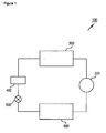
- FIG.1 is a block diagram showing a refrigeration cycle of an automotive air conditioning system
- FIG.2 is a front view showing a condenser with doesn't fall under the scope of claim 1.
- FIG.3 is an entire cross-sectional view showing an embodiment of a condenser according to the present invention.
- FIG. 4 is a front view showing another embodiment of a condenser
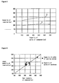
- FIG. 5 is a graph showing the optimal ranges of a capacity values of the receiver with reference to the variations of a total capacity of the condenser.
- FIG. 6 is a graph showing the relationship between the results where the condenser integrated with the receiver according to the invention to which the capacity determined according to the variations of the total capacity of the condenser is applied and that to which the capacity determined according to the variations of the total capacity of the cooling system is applied are respectively employed, and an ideal capacity of the receiver.
- a refrigeration cycle 100 of an automobile air conditioning device includes a compressor 200, a condenser 300, a receiver 400, an expansion valve 500, and an evaporator 600.
- the refrigerant is compressed in the compressor 200 and delivered at high temperature and high pressure to the condenser 300.
- the refrigerant is condensed into a liquid phases and is passed through the receiver 400 and through the expansion valve 500. While passing, the refrigerant becomes at lower temperature and lower pressure and flows into the evaporator 600. Next, the refrigerant is thermally exchanged with around air, delivered to the compressor 200 and circulated in the refrigeration cycle.
- the condenser 300 of the refrigeration cycle 100 comprises, as shown in FIG. 2 , a core 303 that is provided with a plurality of tubes 301 that are arranged in parallel with one another and a plurality of fins 302 that are interposed alternately between adjacent tubes 301.
- the plurality of tubes 301 are connected to a first header 310 at the one ends thereof and to a second header 311 at the other ends thereof.
- the condenser 300 further comprises a pair of side plates 320 and 321 disposed at the outmost portion thereof.
- each the headers 310 and 311 are closed by caps 330 and 331.
- the first header 310 is connected to an inlet pipe 340 at the upper portion thereof and to an outlet pipe 341 at the lower portion thereof.
- the outlet pipe 341 may be connected to the second header 311 differently from FIG. 2 .
- Such location of the inlet/outlet pipe may be determined in relation with the number of paths formed.
- Both the first and second headers 310 and 311 are provided with baffles 350 to define a plurality of refrigerant flow paths each defined by the plurality of tubes 301.
- the refrigerant introduced into the condenser 300 provided with the above-mentioned construction is condensed into a liquid phase and delivered toward an external receiver 400 via a conduit 342 connected to the outlet pipe 341 and then, stored therein.
- a certain capacity of refrigerant is maintained in the receiver 400 so as to deal with rapid variation of the amount of refrigerant circulated according to variations of the thermal load.
- the receiver 400 is normally provided with a desiccant (which is not shown in FIG. 2 ) for removing water from refrigerant, in the inside thereof and with a lower cap (which is not also shown) for opening and closing the lower portion thereof.
- a desiccant which is not shown in FIG. 2
- a lower cap which is not also shown
- the receiver 400 may be disposed on one of the first and second headers 310 and 311, on the drawing, the receiver 400 is disposed on the second header 311. While the gaseous refrigerant introduced into the condenser 300 through the inlet pipe 340 flows through the refrigerant paths in the condenser 300, a first separation of gaseous and liquid phases of the refrigerant occurs within the first and the second header 310, 311.
- Refrigerant is introduced into the receiver 400 via communication passageways 360, 361 and 362 disposed between the second header 311 and the receiver 400, wherein a second separation of gaseous and liquid phases of the refrigerant occurs within the receiver 400.
- the condenser integrated with the receiver is employed such that the refrigerant discharged from the condenser 300 is maintained at the liquid phases.
- the receiver 400 is further provided with a desiccant 410 for removing water from refrigerant, in the inside thereof and with a lower cap 420 for opening and closing the lower portion thereof.
- FIG. 4 shows another condenser arrangement where the first and second headers 310 and 311 are arranged upward and downward in parallel with each other and a plurality of tubes 301 are disposed vertically between the first and second headers 310 and 311 such that the refrigerant flows vertically to the receiver 400. This is called 'down flow type'.
- the present invention is directed to the refrigeration cycle that has a compressor, a condenser, with a receiver, an expansion valve and an evaporator, wherein a correlative relationship between a capacity of the condenser and a capacity of the receiver is obtained, and with the relationship, the capacity of the receiver can be easily obtained.
- the refrigeration cycle that has the compressor 200, the condenser 300, the receiver 400, the expansion valve 500 and the evaporator 600 that are sequentially connected via refrigerant pipes so as to flow refrigerant therethrough, wherein if a capacity of the condenser 300 is represented by CVT and a capacity of the receiver 400 is represented by RV, a first relational expression as described below is satisfied. 29.71 ⁇ ln CVT + 35 ⁇ RV ⁇ 41.103 ⁇ ln CVT + 74.3
- the present inventors found that if the first relational expression is satisfied, the refrigeration cycle carries out refrigerant supply in more stable manner dealing with the variations of the cooling load, thereby completely preventing the efficiency of the refrigeration cycle from being substantially low.
- the optimal capacity RV of the receiver as obtained by experiments satisfies a second relational expression as described below. 220 ⁇ cc ⁇ RV ⁇ 350 ⁇ cc
- a capacity RIV of the internal space of the receiver 400 satisfies a third relational expression as described below. 29.71 ⁇ ln CVT - 15 ⁇ RIV ⁇ 41.103 ⁇ ln CVT + 24.268
- the present inventors found that if the third relational expression is satisfied, the refrigeration cycle carries out refrigerant supply in more stable manner dealing with the variations of the cooling load, thereby completely preventing the efficiency of the refrigeration cycle from being substantially low.
- the capacity RIV of the internal space of the receiver as obtained by experiments satisfies a fourth relational expression as described below. 150 ⁇ cc ⁇ RIV ⁇ 250 ⁇ cc
- a method for determining a capacity of the receiver in the refrigeration cycle that has the compressor 200, the condenser 300, the receiver 400, the expansion valve 500 and the evaporator 600 that are sequentially connected via refrigerant pipes so as to flow refrigerant therethrough, wherein if a capacity of the condenser 300 is represented by CVT and a capacity of the receiver 400 is represented by RV, the first relational expression as described below is satisfied. 29.71 ⁇ ln CVT + 35 ⁇ RV ⁇ 41.103 ⁇ ln CVT + 74.3
- the capacity RV of the receiver as obtained by experiments satisfies the second relational expression as described below. 220 ⁇ cc ⁇ RV ⁇ 350 ⁇ cc
- FIG. 5 is a graph showing relation of the total capacity CVT of the condenser 300 and the capacity RV of the receiver 400.
- a line A shows a variation of the maximum values of the capacity RV of the receiver 400 with reference to the variations of the total capacity CVT of the condenser 300, and to the contrary, a line B shows the variation of the minimum values of the capacity RV of the receiver 400 with reference to the variations of the total capacity CVT of the condenser 300.
- the capacity RV of the receiver 400 according to the present invention is determined in the range between the lines A and B with reference to the total capacity CVT of the condenser 300.
- FIG. 6 is a graph showing the relationship between the results where the condenser integrated with the receiver to which the capacity RV determined according to the variations of the total capacity CVT of the condenser is applied and that to which the capacity determined according to the variations of the total capacity of the cooling system is applied are respectively employed, and an ideal capacity of the receiver.
- the receiver 400 which has the capacity RV determined according to the variations of the total capacity CVT of the condenser, is in the range adjacent to the ideal capacity of the receiver, in the same manner as that having the capacity determined according to the total variations of the cooling system.
- the capacity RV of the receiver 400 can be determined simply according to the variations of the total capacity CVT of the condenser 300, not according to the variations of total capacity of the cooling system, which ensures that refrigerant supply is stably carried out according to the variations of the cooling load. Thereby no decrease the efficiency of the refrigeration cycle occurs.
- the capacity RV of the receiver 400 can be determined according to the variations of the total capacity of the condenser, which provides an ability of fully coping with the variations of the cooling load.
- the method for determining the capacity of the receiver according to the present invention is applied in the condenser integrated with the receiver, it is possible that an optimal capacity where no brazing failure occurs is obtained, which means the optimal capacity for the receiver 400 can be easily determined.
Landscapes
- Engineering & Computer Science (AREA)
- Physics & Mathematics (AREA)
- Mechanical Engineering (AREA)
- Thermal Sciences (AREA)
- General Engineering & Computer Science (AREA)
- Chemical & Material Sciences (AREA)
- Analytical Chemistry (AREA)
- Power Engineering (AREA)
- Air-Conditioning For Vehicles (AREA)
- Cooling Or The Like Of Semiconductors Or Solid State Devices (AREA)
- Testing Of Individual Semiconductor Devices (AREA)
- Detail Structures Of Washing Machines And Dryers (AREA)
Description
- The present invention relates to a refrigeration cycle and a method for determining a capacity of a receiver of a refrigeration cycle.
- One of the conventional refrigeration cycles is disclosed in Japanese Patent Laid-open No.
9-33139 published on February 7, 1997 - The prior art refrigeration cycle comprises a refrigerant compressor that is adapted to compress refrigerant, a refrigerant condenser that is provided with a plurality of condensing tube portion for condensing the refrigerant flowing from the refrigerant compressor and with a refrigerant combining portion for combining the refrigerants flowing from the plurality of condensing tube portion, a receiver that separates the refrigerant from the refrigerant combining portion of the refrigerant condenser into gaseous and liquid refrigerant to make only liquid refrigerant flow, a supercooling device that is provided with a refrigerant distribution portion for distributing the refrigerant flowing from the receiver and with a supercooling tube portion for supercooling the refrigerant distributed from the refrigerant distribution portion, a sight glass that is adapted to watch the state of the refrigerant flowing from the supercooling device, an expansion valve that is adapted to make the refrigerant flowing from the sight glass expanded, and a refrigerant evaporator that is adapted to make the refrigerant flowing from the expansion valve evaporated. If a required capacity of the fluid receiver is represented by VR, a sum of a capacity of the refrigerant condenser and a capacity of the supercooling device is represented by VCOND, a capacity of the refrigerant evaporator is represented by VEVA, a capacity of the supercooling tube portion is represented by VSC, and a sum of capacity of the refrigerant combining portion and a capacity of the refrigerant distribution portion is represented by Vh, relational expressions as described below;


are satisfied. - The above-mentioned refrigeration cycle is capable of providing a relatively small-sized receiver and preventing an effective heat exchanging area of a core of the refrigerant condenser from being reduced.
- However, the components of the refrigeration cycle have different specifications according to the kind of vehicle and the variations of the cooling load is substantially irregular, such that it is difficult to measure a total capacity in the refrigeration cycle. Therefore, it is not easy that the above-described relational expressions shown in the conventional refrigeration cycle are actually applied.
- Upon the process of brazing, besides, the refrigerant condenser integrated with the receiver is not heated evenly in a brazing furnace due to the variations of the heat capacity caused by the change of the capacity of the receiver, which causes a brazing failure that will result in an increase of the number of bad products.
- To avoid the brazing failure, the receiver is designed to have a relatively small capacity, but this is not considered that the local temperature difference in the brazing furnace still exists. Moreover, a correlative relationship between the refrigerant condenser and the receiver is not considered at all, and as the amount of stocked refrigerant of the receiver is decreased, refrigerant supply is not carried out stably in accordance with the variations of the cooling load. This of course causes the efficiency of the refrigeration cycle to be greatly low. The documents J BERNIER: "La reserve de Liquide haute pression:Pourquoi? Quand? Combien? REVUE PRATIQUE DU FROID ET DU CONDITIONNEMENT D'AIR, vol 46, no 732, 25 June 1991, pages 104-107 shows a refrigeration cycle with a compressor, a condenser, a receiver, an expansion valve and an evaporator, but the apparatus does not achieve the parameters as set out in the claims. The document M. PARRINO ET AL: "Capacita del recivitore c prestazioni dei condizionatori d'auto "ZERO SOTTO ZERO, vol 8 no 7 October 1999, pages 84-93" does not disclose details relating to a condenser capacity.
DocumentUS2001 /00398809 - Accordingly, the present invention is directed to a refrigeration cycle and a method for determining a capacity of a receiver of a refrigeration cycle that substantially obviates one or more problems due to limitations and disadvantages of the related art.
- An object of the present invention is to provide a refrigeration cycle that is provided with a compressor, a condenser, a receiver, an expansion valve and an evaporator, wherein a correlative relationship between a capacity of the condenser and a capacity of the receiver is obtained, and with the relational expression, the capacity of the receiver can be easily obtained
- Another object of the present invention is to provide a method for determining a capacity of a receiver in a refrigeration cycle that has a compressor, a condenser, the receiver, an expansion valve and an evaporator, wherein the capacity of the receiver can be easily obtained by using a capacity of the condenser.
- Additional advantages, objects, and features of the invention will be set forth in part in the description which follows and in part will become apparent to those having ordinary skill in the art upon examination of the following or may be learned from practice of the invention. The objectives and other advantages of the invention may be realized and attained by the structure particularly pointed out in the written description and claims hereof as well as the appended drawings.
- According to an aspect of the present invention, there is provided a refrigeration cycle comprising a compressor, a condenser, a receiver, an expansion valve and an evaporator, said condenser which is used is a receiver integrated subcool condenser in which there is provided a sub-cool area for super-cooling the refrigerant passed from the receiver and characterised in that the capacity of said condenser is represented by CVT and the capacity of said receiver is represented by RVand the relational expression of 29.71 x In (CVT) + 35 ≤ RV ≤ 41.103 x In (CVT) + 74.3 is satisfied.
- According to another aspect of the present invention, there is provided a method for determining a capacity of a receiver in a refrigeration cycle that has a compressor, a condenser, a receiver, an expansion valve and an evaporator, the condenser is a receiver integrated subcool condenser and the refrigerant is passed from the receiver to a sub-cool area of the sub-cool condenser to supercool the refrigerant and characterised in that the capacity of the condenser is represented by CVT and the capacity of said receiver is represented by RV and the relational expression of 29.71 x In (CVT)+ 35 ≤ RV ≤ 41.103 x In (CVT) + 74.3 is satisfied.
- It is to be understood that both the foregoing general description and the following detailed description of the present invention are exemplary and explanatory and are intended to provide further explanation of the invention as claimed.
- The accompanying drawings, which are included to provide a further understanding of the invention and are incorporated in and constitute a part of this application, illustrate embodiment(s) of the invention and together with the description serve to explain the principle of the invention. In the drawings;
-
FIG.1 is a block diagram showing a refrigeration cycle of an automotive air conditioning system; -
FIG.2 is a front view showing a condenser with doesn't fall under the scope of claim 1. -
FIG.3 is an entire cross-sectional view showing an embodiment of a condenser according to the present invention; - -
FIG. 4 is a front view showing another embodiment of a condenser; -
FIG. 5 is a graph showing the optimal ranges of a capacity values of the receiver with reference to the variations of a total capacity of the condenser; and -
FIG. 6 is a graph showing the relationship between the results where the condenser integrated with the receiver according to the invention to which the capacity determined according to the variations of the total capacity of the condenser is applied and that to which the capacity determined according to the variations of the total capacity of the cooling system is applied are respectively employed, and an ideal capacity of the receiver. - Reference will now be made in detail to the invention;
- As shown in
FIG.1 , arefrigeration cycle 100 of an automobile air conditioning device, includes acompressor 200, acondenser 300, areceiver 400, anexpansion valve 500, and anevaporator 600. - In the
refrigeration cycle 100, the refrigerant is compressed in thecompressor 200 and delivered at high temperature and high pressure to thecondenser 300. - After that, the refrigerant is condensed into a liquid phases and is passed through the
receiver 400 and through theexpansion valve 500. While passing, the refrigerant becomes at lower temperature and lower pressure and flows into theevaporator 600. Next, the refrigerant is thermally exchanged with around air, delivered to thecompressor 200 and circulated in the refrigeration cycle. - The
condenser 300 of therefrigeration cycle 100 comprises, as shown inFIG. 2 , acore 303 that is provided with a plurality oftubes 301 that are arranged in parallel with one another and a plurality offins 302 that are interposed alternately betweenadjacent tubes 301. - The plurality of
tubes 301 are connected to afirst header 310 at the one ends thereof and to asecond header 311 at the other ends thereof. - The
condenser 300 further comprises a pair ofside plates - The both ends of each the
headers caps - The
first header 310 is connected to aninlet pipe 340 at the upper portion thereof and to anoutlet pipe 341 at the lower portion thereof. Theoutlet pipe 341 may be connected to thesecond header 311 differently fromFIG. 2 . Such location of the inlet/outlet pipe may be determined in relation with the number of paths formed. - Both the first and
second headers baffles 350 to define a plurality of refrigerant flow paths each defined by the plurality oftubes 301. - The refrigerant introduced into the
condenser 300 provided with the above-mentioned construction is condensed into a liquid phase and delivered toward anexternal receiver 400 via aconduit 342 connected to theoutlet pipe 341 and then, stored therein. - A certain capacity of refrigerant is maintained in the
receiver 400 so as to deal with rapid variation of the amount of refrigerant circulated according to variations of the thermal load. - The
receiver 400 is normally provided with a desiccant (which is not shown inFIG. 2 ) for removing water from refrigerant, in the inside thereof and with a lower cap (which is not also shown) for opening and closing the lower portion thereof. - In the conventional refrigerant system shown in
Figures 1 and2 , thecondenser 300 and thereceiver 400 are separately provided. - Next, an embodiment of the condenser in accordance with the principles of the present invention are applied is shown. As shown in
FIG. 3 , thereceiver 400 may be disposed on one of the first andsecond headers receiver 400 is disposed on thesecond header 311. While the gaseous refrigerant introduced into thecondenser 300 through theinlet pipe 340 flows through the refrigerant paths in thecondenser 300, a first separation of gaseous and liquid phases of the refrigerant occurs within the first and thesecond header receiver 400 viacommunication passageways second header 311 and thereceiver 400, wherein a second separation of gaseous and liquid phases of the refrigerant occurs within thereceiver 400. In this embodiment, the condenser integrated with the receiver is employed such that the refrigerant discharged from thecondenser 300 is maintained at the liquid phases. - In this case, the
receiver 400 is further provided with a desiccant 410 for removing water from refrigerant, in the inside thereof and with alower cap 420 for opening and closing the lower portion thereof. -
FIG. 4 shows another condenser arrangement where the first andsecond headers tubes 301 are disposed vertically between the first andsecond headers receiver 400. This is called 'down flow type'. - As noted above, the present invention is directed to the refrigeration cycle that has a compressor, a condenser, with a receiver, an expansion valve and an evaporator, wherein a correlative relationship between a capacity of the condenser and a capacity of the receiver is obtained, and with the relationship, the capacity of the receiver can be easily obtained.
- In more detail, there is provided the refrigeration cycle that has the
compressor 200, thecondenser 300, thereceiver 400, theexpansion valve 500 and theevaporator 600 that are sequentially connected via refrigerant pipes so as to flow refrigerant therethrough, wherein if a capacity of thecondenser 300 is represented by CVT and a capacity of thereceiver 400 is represented by RV, a first relational expression as described below is satisfied.

- The present inventors found that if the first relational expression is satisfied, the refrigeration cycle carries out refrigerant supply in more stable manner dealing with the variations of the cooling load, thereby completely preventing the efficiency of the refrigeration cycle from being substantially low. The optimal capacity RV of the receiver as obtained by experiments satisfies a second relational expression as described below.

- And, the present inventors found that in case where the
receiver 400 is provided with thedesiccant 410 and thelower cap 420, a capacity RIV of the internal space of thereceiver 400 satisfies a third relational expression as described below.

- The present inventors found that if the third relational expression is satisfied, the refrigeration cycle carries out refrigerant supply in more stable manner dealing with the variations of the cooling load, thereby completely preventing the efficiency of the refrigeration cycle from being substantially low. The capacity RIV of the internal space of the receiver as obtained by experiments satisfies a fourth relational expression as described below.

- According to the present invention, on the other hand, there is provided a method for determining a capacity of the receiver in the refrigeration cycle that has the
compressor 200, thecondenser 300, thereceiver 400, theexpansion valve 500 and theevaporator 600 that are sequentially connected via refrigerant pipes so as to flow refrigerant therethrough, wherein if a capacity of thecondenser 300 is represented by CVT and a capacity of thereceiver 400 is represented by RV, the first relational expression as described below is satisfied.

- Moreover, if the first relational expression is satisfied, the capacity RV of the receiver as obtained by experiments satisfies the second relational expression as described below.

-
FIG. 5 is a graph showing relation of the total capacity CVT of thecondenser 300 and the capacity RV of thereceiver 400. - A line A shows a variation of the maximum values of the capacity RV of the
receiver 400 with reference to the variations of the total capacity CVT of thecondenser 300, and to the contrary, a line B shows the variation of the minimum values of the capacity RV of thereceiver 400 with reference to the variations of the total capacity CVT of thecondenser 300. - That is to say, the capacity RV of the
receiver 400 according to the present invention is determined in the range between the lines A and B with reference to the total capacity CVT of thecondenser 300. -
FIG. 6 is a graph showing the relationship between the results where the condenser integrated with the receiver to which the capacity RV determined according to the variations of the total capacity CVT of the condenser is applied and that to which the capacity determined according to the variations of the total capacity of the cooling system is applied are respectively employed, and an ideal capacity of the receiver. - As understood from the graph, the
receiver 400, which has the capacity RV determined according to the variations of the total capacity CVT of the condenser, is in the range adjacent to the ideal capacity of the receiver, in the same manner as that having the capacity determined according to the total variations of the cooling system. - As clearly discussed above, therefore, the capacity RV of the
receiver 400 can be determined simply according to the variations of the total capacity CVT of thecondenser 300, not according to the variations of total capacity of the cooling system, which ensures that refrigerant supply is stably carried out according to the variations of the cooling load. Thereby no decrease the efficiency of the refrigeration cycle occurs. - According to the present invention, the capacity RV of the
receiver 400 can be determined according to the variations of the total capacity of the condenser, which provides an ability of fully coping with the variations of the cooling load. - When the method for determining the capacity of the receiver according to the present invention is applied in the condenser integrated with the receiver, it is possible that an optimal capacity where no brazing failure occurs is obtained, which means the optimal capacity for the
receiver 400 can be easily determined. - When the condenser integrated with the receiver having the capacity determined by the method of the present invention is brazed, it can be understood that a probability for the generation of bad products due to the brazing failure can be reduced, which enables the productivity of the condenser to be enhanced and further allows the production cost to be substantially reduced.
Claims (9)
- A refrigeration cycle comprising a compressor (200), a condenser (300), a receiver (400), an expansion valve (500), an evaporator (600) said condenser (300) which is used is a receiver integrated sub-cool condenser in which there is provided a subcool area for supercooling the refrigerant passed from the receiver (400), characterized in that the capacity of said condenser (300) is represented by CVT and the capacity of said receiver (400) is represented by RV and the relational expression of 29.71×ln(CVT)+35≤RV≤41.103×ln(CVT)+74.3 is satisfied.
- The refrigeration cycle according to claim 1, characterized in that said capacity RV of said receiver (400) satisfies a relational expression of 220cc≤RV≤350cc.
- The refrigeration cycle according to claim 1, characterized in that said receiver (400) is further provided with a desiccant (410) and a lower cap (420), and a capacity RIV of the internal space of said receiver (400) occupied by the refrigerant satisfies a relational expression of 29.71×ln(CVT)-15≤RIV≤41.103×ln(CVT)+24.268.
- The refrigeration cycle according to claim 3, characterized in that said capacity RIV of the internal space of said receiver (400) satisfies a relational expression of 150cc≤RIV≤250cc.
- The refrigeration cycle according to claim 1, characterized in that said condenser (300) comprises:the first and second headers (310) and (311);a plurality of tubes (301) each connected to said first and second headers (310) and (311) at opposite ends thereof;a plurality of fins (302) interposed between adjacent tubes (301); andinlet and outlet pipes (340) and (341) connected to one of said first and second headers (310) and (311).
- The refrigeration cycle according to claim 1, characterized in that said condenser (300) comprises:first and second headers (310) and (311) disposed upward and downward in parallel with each other;a plurality of tubes (301) each connected to said first and second headers (310) and (311) at opposite ends thereof;a plurality of fins (302) interposed between adjacent tubes (301); andInlet and outlet pipes (340) and (341) connected to one of said first and second headers (310) and (311).
- The refrigeration cycle according to claim 1, characterized in that said condenser (300) is formed integrally with said receiver (400).
- A method for determining a capacity of a receiver in a refrigeration cycle that has a compressor (200), a condenser (300), a receiver (400), an expansion valve (500) and an evaporator (600), and the condenser (300) used is a receiver integrated sub-cool condenser and the refrigerant is passed from the receiver (400) to a sub-cool area of the sub-cool condenser to supercool the refrigerant and characterised in that the capacity of said condenser (300) is represented by CVT and the capacity of said receiver (400) is represented by RV, and the relational expression of 29.71×ln(CVT)+35≤RV≤41.103× ln(CVT)+74.3 is satisfied.
- The method according to claim 8, characterized in that the capacity RV of said receiver (400) satisfies a relational expression of 220cc≤RV≤350cc.
Applications Claiming Priority (2)
| Application Number | Priority Date | Filing Date | Title |
|---|---|---|---|
| KR2001081387 | 2001-12-19 | ||
| KR1020010081387A KR100654178B1 (en) | 2001-12-19 | 2001-12-19 | Receiver dryer volume determination method and receiver dryer integrated condenser having a volume determined by the method |
Publications (3)
| Publication Number | Publication Date |
|---|---|
| EP1321729A2 EP1321729A2 (en) | 2003-06-25 |
| EP1321729A3 EP1321729A3 (en) | 2003-08-06 |
| EP1321729B1 true EP1321729B1 (en) | 2008-07-02 |
Family
ID=19717260
Family Applications (1)
| Application Number | Title | Priority Date | Filing Date |
|---|---|---|---|
| EP02028338A Revoked EP1321729B1 (en) | 2001-12-19 | 2002-12-17 | Refrigeration cycle and method for determining capacity of receiver thereof |
Country Status (6)
| Country | Link |
|---|---|
| US (1) | US6640585B2 (en) |
| EP (1) | EP1321729B1 (en) |
| JP (1) | JP3764904B2 (en) |
| KR (1) | KR100654178B1 (en) |
| CN (1) | CN1324279C (en) |
| DE (1) | DE60227337D1 (en) |
Families Citing this family (7)
| Publication number | Priority date | Publication date | Assignee | Title |
|---|---|---|---|---|
| US6317760B1 (en) * | 1998-01-14 | 2001-11-13 | Microsoft Corporation | Extensible ordered information within a web page |
| JP4089567B2 (en) * | 2003-09-16 | 2008-05-28 | 株式会社デンソー | Heat exchanger module for cooling |
| JP4232750B2 (en) * | 2004-06-10 | 2009-03-04 | 株式会社デンソー | Hybrid vehicle cooling system |
| JP5651431B2 (en) * | 2010-11-08 | 2015-01-14 | 株式会社ケーヒン・サーマル・テクノロジー | Capacitor |
| JP5759076B2 (en) * | 2012-09-06 | 2015-08-05 | 三菱電機株式会社 | Refrigeration equipment |
| JP6119488B2 (en) * | 2013-07-30 | 2017-04-26 | 株式会社デンソー | Receiver and receiver-integrated condenser |
| WO2015111222A1 (en) * | 2014-01-27 | 2015-07-30 | 三菱電機株式会社 | Refrigeration device |
Family Cites Families (12)
| Publication number | Priority date | Publication date | Assignee | Title |
|---|---|---|---|---|
| US4909042A (en) * | 1987-12-10 | 1990-03-20 | Murray Corporation | Air conditioner charging station with same refrigerant reclaiming and liquid refrigerant return and method |
| JP3013492B2 (en) * | 1990-10-04 | 2000-02-28 | 株式会社デンソー | Refrigeration apparatus, heat exchanger with modulator, and modulator for refrigeration apparatus |
| JP3243924B2 (en) * | 1994-04-01 | 2002-01-07 | 株式会社デンソー | Refrigerant condenser |
| JP3644077B2 (en) * | 1995-07-18 | 2005-04-27 | 株式会社デンソー | Refrigeration cycle |
| JP3116996B2 (en) * | 1996-10-30 | 2000-12-11 | 株式会社デンソー | Recipient integrated refrigerant condenser |
| US6000465A (en) * | 1997-06-27 | 1999-12-14 | Mitsubishi Heavy Industries, Ltd. | Heat exchange with a receiver |
| US6374632B1 (en) * | 1998-06-16 | 2002-04-23 | Denso Corporation | Receiver and refrigerant cycle system |
| JP2002031436A (en) * | 2000-05-09 | 2002-01-31 | Sanden Corp | Sub-cooling type condenser |
| JP4569041B2 (en) * | 2000-07-06 | 2010-10-27 | 株式会社デンソー | Refrigeration cycle equipment for vehicles |
| US6330810B1 (en) * | 2000-08-11 | 2001-12-18 | Showa Denko K.K. | Condensing apparatus for use in a refrigeration cycle receiver-dryer used for said condensing apparatus |
| JP2002162134A (en) * | 2000-11-20 | 2002-06-07 | Denso Corp | Refrigeration cycle device |
| JP2002187424A (en) * | 2000-12-19 | 2002-07-02 | Denso Corp | Vehicle condenser |
-
2001
- 2001-12-19 KR KR1020010081387A patent/KR100654178B1/en not_active Expired - Lifetime
-
2002
- 2002-12-17 DE DE60227337T patent/DE60227337D1/en not_active Expired - Lifetime
- 2002-12-17 EP EP02028338A patent/EP1321729B1/en not_active Revoked
- 2002-12-19 JP JP2002368926A patent/JP3764904B2/en not_active Expired - Lifetime
- 2002-12-19 US US10/323,297 patent/US6640585B2/en not_active Expired - Lifetime
- 2002-12-19 CN CNB021586705A patent/CN1324279C/en not_active Expired - Lifetime
Also Published As
| Publication number | Publication date |
|---|---|
| US6640585B2 (en) | 2003-11-04 |
| JP2003207230A (en) | 2003-07-25 |
| US20030110793A1 (en) | 2003-06-19 |
| CN1430031A (en) | 2003-07-16 |
| EP1321729A3 (en) | 2003-08-06 |
| JP3764904B2 (en) | 2006-04-12 |
| CN1324279C (en) | 2007-07-04 |
| KR100654178B1 (en) | 2006-12-05 |
| DE60227337D1 (en) | 2008-08-14 |
| KR20030050852A (en) | 2003-06-25 |
| EP1321729A2 (en) | 2003-06-25 |
Similar Documents
| Publication | Publication Date | Title |
|---|---|---|
| US6032482A (en) | Constructional collector heat transfer unit and air conditioner equipped therewith | |
| US5592830A (en) | Refrigerant condenser with integral receiver | |
| US6062303A (en) | Multiflow type condenser for an air conditioner | |
| US8662148B2 (en) | Heat exchanger | |
| US9335077B2 (en) | Condenser with first header tank and second header tank provided on one side of the condenser | |
| US8590604B2 (en) | Double-wall-tube heat exchanger | |
| EP1942305B1 (en) | Internal heat exchanger integrated with gas cooler | |
| EP0779481A2 (en) | Refrigeration cycle system | |
| US20010039809A1 (en) | Subcooling-type condenser | |
| JP2001091104A (en) | Assembled body of evaporator/accumulator/suction line heat exchanger | |
| US6250103B1 (en) | Condenser and air conditioning refrigeration system and using same | |
| KR20070096992A (en) | Heat exchanger module | |
| US12157349B2 (en) | Heat exchanger | |
| US20130333402A1 (en) | Climate control systems for motor vehicles and methods of operating the same | |
| US20110061845A1 (en) | Heat exchanger | |
| JP2827404B2 (en) | Refrigerant condenser | |
| EP2664867A1 (en) | Refrigeration cycle and condenser with supercooling unit | |
| US6640585B2 (en) | Refrigeration cycle and method for determining capacity of receiver thereof | |
| KR101385194B1 (en) | A Condenser | |
| US20030062152A1 (en) | Radiator for supercritical vapor compression type refrigerating cycle | |
| US20070056718A1 (en) | Heat exchanger and duplex type heat exchanger | |
| EP2613116B1 (en) | Method for determining a configuration of a heat exchanger | |
| GB2377268A (en) | A heat exchanger with isolated cooling circuits | |
| EP3862654B1 (en) | Refrigerant vapor compression system with multiple flash tanks | |
| KR19980061128A (en) | Condenser formed a combined flow path with receiver dryer |
Legal Events
| Date | Code | Title | Description |
|---|---|---|---|
| PUAI | Public reference made under article 153(3) epc to a published international application that has entered the european phase |
Free format text: ORIGINAL CODE: 0009012 |
|
| PUAL | Search report despatched |
Free format text: ORIGINAL CODE: 0009013 |
|
| AK | Designated contracting states |
Designated state(s): AT BE BG CH CY CZ DE DK EE ES FI FR GB GR IE IT LI LU MC NL PT SE SI SK TR |
|
| AX | Request for extension of the european patent |
Extension state: AL LT LV MK RO |
|
| AK | Designated contracting states |
Designated state(s): AT BE BG CH CY CZ DE DK EE ES FI FR GB GR IE IT LI LU MC NL PT SE SI SK TR |
|
| AX | Request for extension of the european patent |
Extension state: AL LT LV MK RO |
|
| 17P | Request for examination filed |
Effective date: 20030915 |
|
| AKX | Designation fees paid |
Designated state(s): DE FR GB IT PT SE |
|
| 17Q | First examination report despatched |
Effective date: 20050704 |
|
| 17Q | First examination report despatched |
Effective date: 20050704 |
|
| GRAP | Despatch of communication of intention to grant a patent |
Free format text: ORIGINAL CODE: EPIDOSNIGR1 |
|
| GRAS | Grant fee paid |
Free format text: ORIGINAL CODE: EPIDOSNIGR3 |
|
| GRAA | (expected) grant |
Free format text: ORIGINAL CODE: 0009210 |
|
| AK | Designated contracting states |
Kind code of ref document: B1 Designated state(s): DE FR GB IT PT SE |
|
| REG | Reference to a national code |
Ref country code: GB Ref legal event code: FG4D |
|
| REF | Corresponds to: |
Ref document number: 60227337 Country of ref document: DE Date of ref document: 20080814 Kind code of ref document: P |
|
| PG25 | Lapsed in a contracting state [announced via postgrant information from national office to epo] |
Ref country code: PT Free format text: LAPSE BECAUSE OF FAILURE TO SUBMIT A TRANSLATION OF THE DESCRIPTION OR TO PAY THE FEE WITHIN THE PRESCRIBED TIME-LIMIT Effective date: 20081202 |
|
| PLBI | Opposition filed |
Free format text: ORIGINAL CODE: 0009260 |
|
| PLAX | Notice of opposition and request to file observation + time limit sent |
Free format text: ORIGINAL CODE: EPIDOSNOBS2 |
|
| 26 | Opposition filed |
Opponent name: BEHR GMBH & CO. KG Effective date: 20090402 |
|
| GBPC | Gb: european patent ceased through non-payment of renewal fee |
Effective date: 20081217 |
|
| PG25 | Lapsed in a contracting state [announced via postgrant information from national office to epo] |
Ref country code: IT Free format text: LAPSE BECAUSE OF FAILURE TO SUBMIT A TRANSLATION OF THE DESCRIPTION OR TO PAY THE FEE WITHIN THE PRESCRIBED TIME-LIMIT Effective date: 20080702 |
|
| PLAF | Information modified related to communication of a notice of opposition and request to file observations + time limit |
Free format text: ORIGINAL CODE: EPIDOSCOBS2 |
|
| PLBB | Reply of patent proprietor to notice(s) of opposition received |
Free format text: ORIGINAL CODE: EPIDOSNOBS3 |
|
| PG25 | Lapsed in a contracting state [announced via postgrant information from national office to epo] |
Ref country code: GB Free format text: LAPSE BECAUSE OF NON-PAYMENT OF DUE FEES Effective date: 20081217 |
|
| PG25 | Lapsed in a contracting state [announced via postgrant information from national office to epo] |
Ref country code: SE Free format text: LAPSE BECAUSE OF FAILURE TO SUBMIT A TRANSLATION OF THE DESCRIPTION OR TO PAY THE FEE WITHIN THE PRESCRIBED TIME-LIMIT Effective date: 20081002 |
|
| APBM | Appeal reference recorded |
Free format text: ORIGINAL CODE: EPIDOSNREFNO |
|
| APBP | Date of receipt of notice of appeal recorded |
Free format text: ORIGINAL CODE: EPIDOSNNOA2O |
|
| APAH | Appeal reference modified |
Free format text: ORIGINAL CODE: EPIDOSCREFNO |
|
| APBQ | Date of receipt of statement of grounds of appeal recorded |
Free format text: ORIGINAL CODE: EPIDOSNNOA3O |
|
| PLAB | Opposition data, opponent's data or that of the opponent's representative modified |
Free format text: ORIGINAL CODE: 0009299OPPO |
|
| R26 | Opposition filed (corrected) |
Opponent name: BEHR GMBH & CO. KG Effective date: 20090402 |
|
| REG | Reference to a national code |
Ref country code: DE Ref legal event code: R082 Ref document number: 60227337 Country of ref document: DE Representative=s name: MOSER & GOETZE PATENTANWAELTE, DE |
|
| REG | Reference to a national code |
Ref country code: FR Ref legal event code: CD Owner name: HALLA VISTEON CLIMATE CONTROL CORPORATION Effective date: 20130827 |
|
| REG | Reference to a national code |
Ref country code: DE Ref legal event code: R082 Ref document number: 60227337 Country of ref document: DE Representative=s name: MOSER GOETZE & PARTNER PATENTANWAELTE MBB, DE Effective date: 20130910 Ref country code: DE Ref legal event code: R082 Ref document number: 60227337 Country of ref document: DE Representative=s name: MOSER & GOETZE PATENTANWAELTE, DE Effective date: 20130910 Ref country code: DE Ref legal event code: R081 Ref document number: 60227337 Country of ref document: DE Owner name: HALLA VISTEON CLIMATE CONTROL CORP., KR Free format text: FORMER OWNER: HALLA CLIMATE CONTROL CORP., DAEJEON, KR Effective date: 20130910 |
|
| PGFP | Annual fee paid to national office [announced via postgrant information from national office to epo] |
Ref country code: FR Payment date: 20140825 Year of fee payment: 13 |
|
| REG | Reference to a national code |
Ref country code: DE Ref legal event code: R064 Ref document number: 60227337 Country of ref document: DE Ref country code: DE Ref legal event code: R103 Ref document number: 60227337 Country of ref document: DE |
|
| APBU | Appeal procedure closed |
Free format text: ORIGINAL CODE: EPIDOSNNOA9O |
|
| PGFP | Annual fee paid to national office [announced via postgrant information from national office to epo] |
Ref country code: DE Payment date: 20140826 Year of fee payment: 13 |
|
| PLAB | Opposition data, opponent's data or that of the opponent's representative modified |
Free format text: ORIGINAL CODE: 0009299OPPO |
|
| RDAF | Communication despatched that patent is revoked |
Free format text: ORIGINAL CODE: EPIDOSNREV1 |
|
| RDAG | Patent revoked |
Free format text: ORIGINAL CODE: 0009271 |
|
| STAA | Information on the status of an ep patent application or granted ep patent |
Free format text: STATUS: PATENT REVOKED |
|
| R26 | Opposition filed (corrected) |
Opponent name: BEHR GMBH & CO. KG Effective date: 20090402 |
|
| 27W | Patent revoked |
Effective date: 20141209 |
|
| REG | Reference to a national code |
Ref country code: DE Ref legal event code: R107 Ref document number: 60227337 Country of ref document: DE |