EP1321715A2 - Improved combination of a premixing chamber and a combustion chamber, with low emission of pollutants, for gas turbines running on liquid and/or gas fuel - Google Patents
Improved combination of a premixing chamber and a combustion chamber, with low emission of pollutants, for gas turbines running on liquid and/or gas fuel Download PDFInfo
- Publication number
- EP1321715A2 EP1321715A2 EP02258738A EP02258738A EP1321715A2 EP 1321715 A2 EP1321715 A2 EP 1321715A2 EP 02258738 A EP02258738 A EP 02258738A EP 02258738 A EP02258738 A EP 02258738A EP 1321715 A2 EP1321715 A2 EP 1321715A2
- Authority
- EP
- European Patent Office
- Prior art keywords
- chamber
- combustion
- improved combination
- combustion chamber
- premixing
- Prior art date
- Legal status (The legal status is an assumption and is not a legal conclusion. Google has not performed a legal analysis and makes no representation as to the accuracy of the status listed.)
- Granted
Links
Images


Classifications
-
- F—MECHANICAL ENGINEERING; LIGHTING; HEATING; WEAPONS; BLASTING
- F23—COMBUSTION APPARATUS; COMBUSTION PROCESSES
- F23R—GENERATING COMBUSTION PRODUCTS OF HIGH PRESSURE OR HIGH VELOCITY, e.g. GAS-TURBINE COMBUSTION CHAMBERS
- F23R3/00—Continuous combustion chambers using liquid or gaseous fuel
- F23R3/42—Continuous combustion chambers using liquid or gaseous fuel characterised by the arrangement or form of the flame tubes or combustion chambers
-
- F—MECHANICAL ENGINEERING; LIGHTING; HEATING; WEAPONS; BLASTING
- F23—COMBUSTION APPARATUS; COMBUSTION PROCESSES
- F23D—BURNERS
- F23D17/00—Burners for combustion simultaneously or alternately of gaseous or liquid or pulverulent fuel
- F23D17/002—Burners for combustion simultaneously or alternately of gaseous or liquid or pulverulent fuel gaseous or liquid fuel
-
- F—MECHANICAL ENGINEERING; LIGHTING; HEATING; WEAPONS; BLASTING
- F23—COMBUSTION APPARATUS; COMBUSTION PROCESSES
- F23R—GENERATING COMBUSTION PRODUCTS OF HIGH PRESSURE OR HIGH VELOCITY, e.g. GAS-TURBINE COMBUSTION CHAMBERS
- F23R3/00—Continuous combustion chambers using liquid or gaseous fuel
- F23R3/28—Continuous combustion chambers using liquid or gaseous fuel characterised by the fuel supply
- F23R3/286—Continuous combustion chambers using liquid or gaseous fuel characterised by the fuel supply having fuel-air premixing devices
-
- F—MECHANICAL ENGINEERING; LIGHTING; HEATING; WEAPONS; BLASTING
- F23—COMBUSTION APPARATUS; COMBUSTION PROCESSES
- F23D—BURNERS
- F23D2204/00—Burners adapted for simultaneous or alternative combustion having more than one fuel supply
- F23D2204/10—Burners adapted for simultaneous or alternative combustion having more than one fuel supply gaseous and liquid fuel
-
- F—MECHANICAL ENGINEERING; LIGHTING; HEATING; WEAPONS; BLASTING
- F23—COMBUSTION APPARATUS; COMBUSTION PROCESSES
- F23D—BURNERS
- F23D2900/00—Special features of, or arrangements for burners using fluid fuels or solid fuels suspended in a carrier gas
- F23D2900/00008—Burner assemblies with diffusion and premix modes, i.e. dual mode burners
Definitions
- the present invention relates to an improved combination of a premixing chamber and a combustion chamber, with low emission of pollutants, for gas turbines running on liquid and/or gas fuel.
- a gas turbine is a machine consisting of a compressor and a turbine with one or more stages, in which these components are interconnected by a rotating shaft and in which a combustion chamber is provided between the compressor and the turbine.
- Air from the external environment is supplied to the compressor for pressurization.
- the pressurized air passes through a duct, terminating in a converging portion, into which a set of injectors supplies fuel which is mixed with the air to form a fuel-air mix for combustion.
- the fuel required for the combustion process which is designed to cause an increase in temperature and enthalpy of the gas, is supplied from a pressurized network and is introduced into the combustion chamber by means of one or more injectors.
- a parallel fuel supply system for generating pilot flames in the proximity of the outlet of the mixing duct, is also generally provided, in order to improve the stability characteristics of the flame.
- the gas at high temperature and high pressure passes through suitable ducts to reach the various stages of the turbine, which converts the enthalpy of the gas to mechanical energy available for a user.
- a second element influencing the design of combustion chambers of gas turbines is the tendency to make combustion take place as near as possible to the dome of the combustion chamber.
- the prior art provides a combination of the premixing type, in other words one in which a premixing chamber is used and is located upstream from the combustion chamber and is separated from the latter by a constriction.
- both this premixing chamber and the combustion chamber are surrounded by a cavity containing pressurized air circulating in the opposite direction to the flow of combustion products leaving this combustion chamber.
- This air is used as the combustion air to be mixed with the fuel in the premixing chamber and as the air for cooling both the combustion chamber and the combustion products.
- the flow of the combustion air from the cavity to the premixing chamber, through apertures provided in the outer surface of the latter, can be constricted, in order to keep emissions of nitrogen oxide pollutants low at all levels of loading of the turbine.
- the constriction is applied as a function of the quantity of fuel used, so that the ratio between the combustion air and the fuel constant is kept at the optimal value.
- annular set of holes is provided for an additional injection of fuel, so that the combustion region immediately downstream from the constriction is enriched with fuel.
- one or more injectors are used, to enable liquid fuel to be used as an alternative to gas fuel or in a complementary way; these injectors produce diffusion flames and, owing to the lack of fuel and air mixing, cause high concentrations of polluting emissions.
- the object of the present invention is therefore to overcome the aforementioned drawbacks, and particularly to provide an improved combination of a premixing chamber and a combustion chamber for gas turbines running on liquid and/or gas fuel, which ensures a low emission of pollutants.
- Another object of the present invention is to provide an improved combination of a premixing chamber and a combustion chamber, with low emission of pollutants, for gas turbines running on liquid and/or gas fuel which also provides good flame stability and reduces the oscillations of pressure in the combustion chamber.
- Yet another object of the present invention is to provide an improved combination of a premixing chamber and a combustion chamber, with low emission of pollutants, for gas turbines running on liquid and/or gas fuel which provides a high combustion efficiency.
- An additional object of the present invention is to provide an improved combination of a premixing chamber and a combustion chamber, with low emission of pollutants, for gas turbines running on liquid and/or gas fuel which can increase the average life of components subjected to high temperatures.
- a further additional object of the present invention is to provide an improved combination of a premixing chamber and a combustion chamber, with low emission of pollutants, for gas turbines running on liquid and/or gas fuel which is particularly reliable, simple and functional, and whose production and maintenance costs are relatively low.
- an improved combination of a premixing chamber and a combustion chamber, with low emission of pollutants, for gas turbines running on liquid and/or gas fuel according to the present invention can be made so that it is fairly easily interchangeable with combustion chambers according to the prior art which have already been installed.
- the combustion chamber 11 has a truncated conical end 11a connected to the premixing chamber 12 by a constriction 13 immediately downstream from which there is the actual combustion region 14, in other words the primary flame region of the chamber 11.
- the whole assembly is also surrounded by a cavity 15 for cooling air 20 which is pressurized by an axial compressor not shown in the figure, and which circulates in the direction of the arrow 16, in other words in the opposite direction to the flow 17 of the combustion products leaving the combustion chamber 11.
- the premixing chamber 12 is also supplied with gas fuel by means of ducts 24 and a radial set of pierced tubes 25, while combustion air 20a is sent from the cavity 15 into the premixing chamber 12 through a set of apertures 26 provided in the casing 27 of the premixing chamber 12.
- apertures 26 interact with corresponding apertures in a drum which is rotatable on the casing 27.
- the drum which is not shown in the figure, is rotated in such a way as to decrease the areas of the apertures 26 according to the quantity of fuel used.
- Vanes 33 are also provided in the premixing chamber 12 and in the proximity of the constriction 13, to ensure that the flow passing through them travels in a specified direction, thus promoting the stabilization of the main flame.
- a circumferential set of parallel burners 34 is fitted outside the constriction 13 in order to create a corresponding annular set of additional flames, concentric with the central main flame, in the combustion region 14, immediately downstream from the constriction 13.
- the burners 34 are supplied with additional fuel through an annular chamber 35 and ducts 36, and also with combustion air.
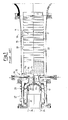
- Figures 2 and 3 show a combination, indicated in its entirety by the number 110, of a premixing chamber 112 and a combustion chamber 111, with low emission of pollutants, for gas turbines running on liquid and/or gas fuel according to the present invention, where components identical and/or equivalent to those shown in Figure 1 with reference to the prior art have the same reference numbers, increased by 100.
- the combustion chamber 111 has a truncated conical end 111a connected to the premixing chamber 112.
- This premixing chamber 112 comprises a central structure 118, which is cylindrical, or slightly tapered in the form of a truncated cone, with a narrowing towards the combustion chamber 111, this structure having its axis coincident with that of the combustion chamber 111 and having within it a liquid fuel injection device 119, positioned axially, in the form of an annular structure for example.
- the central structure 118 is connected downstream to the truncated conical end 111a of the combustion chamber 111, while it is joined upstream, by a connection 138 extending essentially perpendicularly to the axis of the premixing chamber 112 and therefore radially, to an annular chamber 137, which surrounds the central structure 118.
- the end of the annular chamber 137 opposite that at which the annular chamber 137 is joined to the connection 138 has a circumferential set of apertures or ports 126, which are for example rectangular with axial extension, there being twelve of these apertures, which are spaced at equal intervals around a circumference.
- apertures 126 interact with corresponding apertures of a drum 139 which is rotatable on a portion of the annular chamber 137 where the apertures 126 are located.
- the combustion chamber 111 is surrounded by a cavity 115 for cooling air 120 which is pressurized by an axial compressor (not shown in the figure) and which circulates in the direction of the arrow 116, in other words in the opposite direction to the flow 117 of the combustion products leaving the combustion chamber 111.
- Combustion air 120a is sent from the cavity 115 to the apertures 126 of the annular chamber 137.
- the premixing chamber 112 is also supplied with gas fuel through a circumferential set of supply means such as laterally pierced tubes 125, which for example have their axes parallel to the axis of the premixing chamber 112 and are located in the connection 138.
- a circumferential set of supply means such as laterally pierced tubes 125, which for example have their axes parallel to the axis of the premixing chamber 112 and are located in the connection 138.
- the burners 134 are supplied with additional gas fuel through an annular chamber 135 and ducts 136.
- a set of injectors 140 numbering four for example, spaced at equal intervals around a circumference, and supplied with additional liquid fuel, is provided on the truncated conical end 111a and directed towards the interior of the combustion chamber 111.
- the cooling air 120 is pressurized by an axial compressor, not shown in the figures, and cools the combustion chamber 111.
- the air 120 As it cools the combustion chamber 111, the air 120 is heated and enters the annular chamber 137 of the premixing chamber 112 through the apertures 126, thus acting as the combustion air 120a.
- the drum 139 is then rotated in such a way as to reduce the area of the apertures 126 according to the quantity of fuel used.
- Gas fuel is added to this air 120a during its passage through the connection 138.
- the injection device 119 supplies liquid fuel and thus creates the central primary combustion flame.
- the circumferential set of burners 134 creates in the combustion chamber 111, immediately downstream from the truncated conical end 111a, a corresponding annular set of additional pilot flames, concentric with the central primary flame.
- the set of injectors 140 supplies additional liquid fuel, with the aim of further stabilizing the combustion process.
Landscapes
- Engineering & Computer Science (AREA)
- Chemical & Material Sciences (AREA)
- Combustion & Propulsion (AREA)
- Mechanical Engineering (AREA)
- General Engineering & Computer Science (AREA)
- Combustion Of Fluid Fuel (AREA)
Abstract
Description
- reduced levels of polluting emissions with both gas fuel and liquid fuel;
- reduced pressure oscillations in the combustion chamber and good flame stability;
- high combustion efficiency;
- increased average life of components subjected to high temperatures;
- simple and reliable operation;
- relatively low production and maintenance costs as compared with the prior art;
- good interchangeability with combustion chambers known in the prior art, and consequently fairly easy adaptability to gas turbines which have already been installed and which are to be renovated.
Claims (10)
- Improved combination (110) of a premixing chamber (112) and a combustion chamber (111), with low emission of pollutants, for gas turbines running on liquid and/or gas fuel, the said combustion chamber (111) having a truncated conical end (111a), in the proximity of which a main central flame burns, and being surrounded by a cavity (115) for cooling air (120) circulating in the opposite direction to the flow of combustion products, the said cavity (115) carrying combustion air (120a) to the said premixing chamber (112) in which the combustion air is mixed with liquid and/or gas fuel, the said premixing chamber (112) having at its inlet apertures or ports (126) which can be constricted according to the quantity of fuel used, and having at its outlet a circumferential set of burners (134) directed towards the said combustion chamber (111) to create a corresponding set of additional flames concentric with the said main central flame, characterized in that gas fuel supply means (125) and liquid fuel injection devices (119) are provided in the premixing chamber (112), and a set of liquid fuel injectors (140) is present on the truncated conical end (111a) of the said combustion chamber (111), these injectors being directed towards the interior of the combustion chamber (111).
- Improved combination (110) according to Claim 1, characterized in that the said premixing chamber (112) comprises a central structure (118), which is cylindrical, or slightly tapered in the form of a truncated cone, with a narrowing towards the combustion chamber (111), this structure having its axis coincident with that of the said combustion chamber (111) and having within it the said liquid fuel injection device (119) which is positioned axially.
- Improved combination (110) according to Claim 2, characterized in that the said central structure (118) is connected downstream to the truncated conical end (111a) of the combustion chamber (111), while it is joined upstream, by a connection (138) extending essentially perpendicularly to the axis of the premixing chamber (112) and therefore radially, to an annular chamber (137), which surrounds the said central structure (118).
- Improved combination (110) according to Claim 3, characterized in that the said supply means comprise laterally pierced tubes (125) which have their axes parallel to the axis of the premixing chamber (112) and which are located in the connection (138).
- Improved combination (110) according to Claim 1, characterized in that the said burners (134) have their axes parallel to the axis of the premixing chamber (112).
- Improved combination (110) according to Claim 1, characterized in that the said burners (134) are supplied with additional gas fuel through an annular chamber (135) and ducts (136), and also with combustion air.
- Improved combination (110) according to Claim 1, characterized in that the number of the said liquid fuel injectors (140) is four and in that they are positioned at equal intervals around a circumference.
- Improved combination (110) according to Claim 3, characterized in that the said circumferential set of apertures or ports (126) is formed in the said annular chamber (137), at the end opposite that at which the annular chamber (137) is joined to the connection (138).
- Improved combination (110) according to Claim 8, characterized in that the said apertures are rectangular and extend along the axis of the premixing chamber (112), in that the number of these apertures is twelve, and in that they are spaced at equal intervals around a circumference.
- Improved combination (110) according to Claim 1, characterized in that cooling air (120) pressurized by an axial compressor flows through the said cavity (115).
Applications Claiming Priority (2)
| Application Number | Priority Date | Filing Date | Title |
|---|---|---|---|
| ITMI20012781 | 2001-12-21 | ||
| IT2001MI002781A ITMI20012781A1 (en) | 2001-12-21 | 2001-12-21 | IMPROVED ASSEMBLY OF PRE-MIXING CHAMBER AND COMBUSTION CHAMBER, LOW POLLUTING EMISSIONS FOR GAS TURBINES WITH FUEL |
Publications (3)
| Publication Number | Publication Date |
|---|---|
| EP1321715A2 true EP1321715A2 (en) | 2003-06-25 |
| EP1321715A3 EP1321715A3 (en) | 2004-01-14 |
| EP1321715B1 EP1321715B1 (en) | 2008-10-29 |
Family
ID=11448747
Family Applications (1)
| Application Number | Title | Priority Date | Filing Date |
|---|---|---|---|
| EP02258738A Expired - Lifetime EP1321715B1 (en) | 2001-12-21 | 2002-12-18 | Improved combination of a premixing chamber and a combustion chamber, with low emission of pollutants, for gas turbines running on liquid and/or gas fuel |
Country Status (9)
| Country | Link |
|---|---|
| US (1) | US6880339B2 (en) |
| EP (1) | EP1321715B1 (en) |
| JP (1) | JP4362284B2 (en) |
| KR (1) | KR100766143B1 (en) |
| CA (1) | CA2414034C (en) |
| DE (1) | DE60229611D1 (en) |
| IT (1) | ITMI20012781A1 (en) |
| RU (1) | RU2300054C2 (en) |
| TW (1) | TWI280316B (en) |
Cited By (4)
| Publication number | Priority date | Publication date | Assignee | Title |
|---|---|---|---|---|
| WO2007110298A1 (en) * | 2006-03-27 | 2007-10-04 | Alstom Technology Ltd | Burner for the operation of a heat generator |
| WO2007119115A3 (en) * | 2005-12-14 | 2009-03-12 | Rolls Royce Power Eng | Gas turbine engine premix injectors |
| CN103958971A (en) * | 2011-11-28 | 2014-07-30 | 西门子能源有限公司 | Device to lower nox in a gas turbine engine combustion system |
| CN112664977A (en) * | 2019-10-15 | 2021-04-16 | 三菱动力株式会社 | Gas turbine combustor |
Families Citing this family (15)
| Publication number | Priority date | Publication date | Assignee | Title |
|---|---|---|---|---|
| US7093445B2 (en) * | 2002-05-31 | 2006-08-22 | Catalytica Energy Systems, Inc. | Fuel-air premixing system for a catalytic combustor |
| GB2404729B (en) * | 2003-08-08 | 2008-01-23 | Rolls Royce Plc | Fuel injection |
| ITMI20032621A1 (en) * | 2003-12-30 | 2005-06-30 | Nuovo Pignone Spa | COMBUSTION SYSTEM WITH LOW POLLUTING EMISSIONS |
| US7237384B2 (en) * | 2005-01-26 | 2007-07-03 | Peter Stuttaford | Counter swirl shear mixer |
| CA2537685C (en) * | 2006-02-24 | 2013-05-14 | 9131-9277 Quebec Inc. | Fuel injector, burner and method of injecting fuel |
| US20070204624A1 (en) * | 2006-03-01 | 2007-09-06 | Smith Kenneth O | Fuel injector for a turbine engine |
| KR100890824B1 (en) | 2007-11-13 | 2009-03-30 | 한국기계연구원 | Low NOx Gas Turbine System |
| KR100890823B1 (en) | 2007-11-13 | 2009-03-30 | 한국기계연구원 | Gas turbine system |
| KR100862374B1 (en) | 2007-11-13 | 2008-10-13 | 한국기계연구원 | Overheat protection gas turbine system |
| US8863525B2 (en) | 2011-01-03 | 2014-10-21 | General Electric Company | Combustor with fuel staggering for flame holding mitigation |
| JP5807899B2 (en) * | 2011-05-25 | 2015-11-10 | 新潟原動機株式会社 | Gas turbine combustor |
| US20130205799A1 (en) * | 2012-02-15 | 2013-08-15 | Donald Mark Bailey | Outer Fuel Nozzle Inlet Flow Conditioner Interface to End Cap |
| US8966907B2 (en) * | 2012-04-16 | 2015-03-03 | General Electric Company | Turbine combustor system having aerodynamic feed cap |
| JP5958981B2 (en) * | 2015-02-13 | 2016-08-02 | 新潟原動機株式会社 | Method for changing flame lift distance in gas turbine combustor |
| CN114636170B (en) * | 2022-03-18 | 2024-12-20 | 广州发展宝珠能源站有限公司 | A convection vortex wall-cooled burner |
Family Cites Families (20)
| Publication number | Priority date | Publication date | Assignee | Title |
|---|---|---|---|---|
| JPS5129726A (en) * | 1974-09-06 | 1976-03-13 | Mitsubishi Heavy Ind Ltd | |
| GB1570875A (en) * | 1977-03-16 | 1980-07-09 | Lucas Industries Ltd | Combustion equipment |
| US4498288A (en) * | 1978-10-13 | 1985-02-12 | General Electric Company | Fuel injection staged sectoral combustor for burning low-BTU fuel gas |
| US4301653A (en) * | 1979-10-24 | 1981-11-24 | Societe Anonyme D.B.A. | Tandem master cylinder |
| IT1255613B (en) | 1992-09-24 | 1995-11-09 | Eniricerche Spa | LOW EMISSION COMBUSTION SYSTEM FOR GAS TURBINES |
| US5359847B1 (en) * | 1993-06-01 | 1996-04-09 | Westinghouse Electric Corp | Dual fuel ultra-flow nox combustor |
| US5408825A (en) | 1993-12-03 | 1995-04-25 | Westinghouse Electric Corporation | Dual fuel gas turbine combustor |
| US5351477A (en) * | 1993-12-21 | 1994-10-04 | General Electric Company | Dual fuel mixer for gas turbine combustor |
| IT1273369B (en) | 1994-03-04 | 1997-07-08 | Nuovo Pignone Spa | IMPROVED LOW EMISSION COMBUSTION SYSTEM FOR GAS TURBINES |
| AU681271B2 (en) * | 1994-06-07 | 1997-08-21 | Westinghouse Electric Corporation | Method and apparatus for sequentially staged combustion using a catalyst |
| US5657632A (en) * | 1994-11-10 | 1997-08-19 | Westinghouse Electric Corporation | Dual fuel gas turbine combustor |
| EP0918190A1 (en) | 1997-11-21 | 1999-05-26 | Abb Research Ltd. | Burner for the operation of a heat generator |
| DE19803879C1 (en) * | 1998-01-31 | 1999-08-26 | Mtu Muenchen Gmbh | Dual fuel burner |
| RU2162988C2 (en) * | 1999-02-22 | 2001-02-10 | Открытое акционерное общество "Авиадвигатель" | Combustion chamber of gas-turbine plant |
| EP1070915B1 (en) | 1999-07-22 | 2004-05-19 | ALSTOM Technology Ltd | Premix burner |
| GB0019533D0 (en) * | 2000-08-10 | 2000-09-27 | Rolls Royce Plc | A combustion chamber |
| US6422858B1 (en) * | 2000-09-11 | 2002-07-23 | John Zink Company, Llc | Low NOx apparatus and methods for burning liquid and gaseous fuels |
| GB0111788D0 (en) * | 2001-05-15 | 2001-07-04 | Rolls Royce Plc | A combustion chamber |
| ITMI20012785A1 (en) * | 2001-12-21 | 2003-06-21 | Nuovo Pignone Spa | IMPIANT PIPE OR "LINER" IMPROVED FOR A COMBUSTION CHAMBER OF A LOW-EMISSION GAS TURBINE |
| ITMI20012780A1 (en) * | 2001-12-21 | 2003-06-21 | Nuovo Pignone Spa | MAIN INJECTION DEVICE FOR LIQUID FUEL FOR SINGLE COMBUSTION CHAMBER EQUIPPED WITH PRE-MIXING CHAMBER OF A TU |
-
2001
- 2001-12-21 IT IT2001MI002781A patent/ITMI20012781A1/en unknown
-
2002
- 2002-12-12 CA CA002414034A patent/CA2414034C/en not_active Expired - Fee Related
- 2002-12-16 US US10/319,463 patent/US6880339B2/en not_active Expired - Fee Related
- 2002-12-17 TW TW091136424A patent/TWI280316B/en not_active IP Right Cessation
- 2002-12-18 DE DE60229611T patent/DE60229611D1/en not_active Expired - Lifetime
- 2002-12-18 EP EP02258738A patent/EP1321715B1/en not_active Expired - Lifetime
- 2002-12-20 RU RU2002134603/06A patent/RU2300054C2/en not_active IP Right Cessation
- 2002-12-20 KR KR1020020081816A patent/KR100766143B1/en not_active Expired - Fee Related
- 2002-12-20 JP JP2002369156A patent/JP4362284B2/en not_active Expired - Fee Related
Cited By (7)
| Publication number | Priority date | Publication date | Assignee | Title |
|---|---|---|---|---|
| WO2007119115A3 (en) * | 2005-12-14 | 2009-03-12 | Rolls Royce Power Eng | Gas turbine engine premix injectors |
| US8881531B2 (en) | 2005-12-14 | 2014-11-11 | Rolls-Royce Power Engineering Plc | Gas turbine engine premix injectors |
| WO2007110298A1 (en) * | 2006-03-27 | 2007-10-04 | Alstom Technology Ltd | Burner for the operation of a heat generator |
| US7972133B2 (en) | 2006-03-27 | 2011-07-05 | Alstom Technology Ltd. | Burner for the operation of a heat generator and method of use |
| CN103958971A (en) * | 2011-11-28 | 2014-07-30 | 西门子能源有限公司 | Device to lower nox in a gas turbine engine combustion system |
| CN103958971B (en) * | 2011-11-28 | 2016-08-24 | 西门子能源有限公司 | Apparatus for reducing nitrogen oxides in a gas turbine engine combustion system |
| CN112664977A (en) * | 2019-10-15 | 2021-04-16 | 三菱动力株式会社 | Gas turbine combustor |
Also Published As
| Publication number | Publication date |
|---|---|
| CA2414034A1 (en) | 2003-06-21 |
| KR100766143B1 (en) | 2007-10-10 |
| TWI280316B (en) | 2007-05-01 |
| JP2003207132A (en) | 2003-07-25 |
| EP1321715A3 (en) | 2004-01-14 |
| JP4362284B2 (en) | 2009-11-11 |
| US6880339B2 (en) | 2005-04-19 |
| US20050016177A1 (en) | 2005-01-27 |
| TW200411113A (en) | 2004-07-01 |
| RU2300054C2 (en) | 2007-05-27 |
| EP1321715B1 (en) | 2008-10-29 |
| KR20030053438A (en) | 2003-06-28 |
| CA2414034C (en) | 2009-11-17 |
| ITMI20012781A1 (en) | 2003-06-21 |
| DE60229611D1 (en) | 2008-12-11 |
Similar Documents
| Publication | Publication Date | Title |
|---|---|---|
| CA2414034C (en) | Improved combination of a premixing chamber and a combustion chamber, with low emission of pollutants, for gas turbines running on liquid and/or gas fuel | |
| US5289685A (en) | Fuel supply system for a gas turbine engine | |
| EP3320268B1 (en) | Burner for a gas turbine and method for operating the burner | |
| EP0620402B1 (en) | Premix combustor with concentric annular passages | |
| EP0700499B1 (en) | A gas turbine engine combustion chamber | |
| JP4177812B2 (en) | Turbine engine fuel nozzle | |
| EP1426689B1 (en) | Gas turbine combustor having staged burners with dissimilar mixing passage geometries | |
| US6253555B1 (en) | Combustion chamber comprising mixing ducts with fuel injectors varying in number and cross-sectional area | |
| CN100545517C (en) | Method for operating a burner and a gas turbine | |
| EP0692083B1 (en) | Injector having low tip temperature | |
| US6374615B1 (en) | Low cost, low emissions natural gas combustor | |
| EP1795802B1 (en) | Independent pilot fuel control in secondary fuel nozzle | |
| JP5172468B2 (en) | Combustion device and control method of combustion device | |
| KR20150065782A (en) | Combustor with radially staged premixed pilot for improved operability | |
| US6834506B2 (en) | Main liquid fuel injection device for a single combustion chamber, having a premixing chamber, of a gas turbine with low emission of pollutants | |
| JP2001510885A (en) | Burner device for combustion equipment, especially for gas turbine combustors | |
| JP7720928B2 (en) | Gas turbine combustor control method and gas turbine combustor control device | |
| RU2002134603A (en) | THE IMPROVED COMBINATION OF THE PRELIMINARY MIXING CHAMBER AND THE COMBUSTION CHAMBER WITH A SMALL EMISSION OF EMISSIONS FOR GAS TURBINES OPERATING LIQUID AND LIQUID-LIQUID | |
| US20190086089A1 (en) | Burner assembly, combustor, and gas turbine | |
| GB2629434A (en) | Fuel lance for burner of gas turbine engine |
Legal Events
| Date | Code | Title | Description |
|---|---|---|---|
| PUAI | Public reference made under article 153(3) epc to a published international application that has entered the european phase |
Free format text: ORIGINAL CODE: 0009012 |
|
| AK | Designated contracting states |
Designated state(s): AT BE BG CH CY CZ DE DK EE ES FI FR GB GR IE IT LI LU MC NL PT SE SI SK TR |
|
| AX | Request for extension of the european patent |
Extension state: AL LT LV MK RO |
|
| PUAL | Search report despatched |
Free format text: ORIGINAL CODE: 0009013 |
|
| AK | Designated contracting states |
Kind code of ref document: A3 Designated state(s): AT BE BG CH CY CZ DE DK EE ES FI FR GB GR IE IT LI LU MC NL PT SE SI SK TR |
|
| AX | Request for extension of the european patent |
Extension state: AL LT LV MK RO |
|
| 17P | Request for examination filed |
Effective date: 20040714 |
|
| AKX | Designation fees paid |
Designated state(s): CH DE FR GB LI NL |
|
| 17Q | First examination report despatched |
Effective date: 20060113 |
|
| GRAP | Despatch of communication of intention to grant a patent |
Free format text: ORIGINAL CODE: EPIDOSNIGR1 |
|
| GRAS | Grant fee paid |
Free format text: ORIGINAL CODE: EPIDOSNIGR3 |
|
| GRAA | (expected) grant |
Free format text: ORIGINAL CODE: 0009210 |
|
| AK | Designated contracting states |
Kind code of ref document: B1 Designated state(s): CH DE FR GB LI NL |
|
| REG | Reference to a national code |
Ref country code: GB Ref legal event code: FG4D |
|
| REG | Reference to a national code |
Ref country code: CH Ref legal event code: EP |
|
| REG | Reference to a national code |
Ref country code: CH Ref legal event code: NV Representative=s name: SERVOPATENT GMBH |
|
| REF | Corresponds to: |
Ref document number: 60229611 Country of ref document: DE Date of ref document: 20081211 Kind code of ref document: P |
|
| PLBE | No opposition filed within time limit |
Free format text: ORIGINAL CODE: 0009261 |
|
| STAA | Information on the status of an ep patent application or granted ep patent |
Free format text: STATUS: NO OPPOSITION FILED WITHIN TIME LIMIT |
|
| 26N | No opposition filed |
Effective date: 20090730 |
|
| PGFP | Annual fee paid to national office [announced via postgrant information from national office to epo] |
Ref country code: CH Payment date: 20131230 Year of fee payment: 12 Ref country code: GB Payment date: 20131227 Year of fee payment: 12 Ref country code: DE Payment date: 20131230 Year of fee payment: 12 |
|
| PGFP | Annual fee paid to national office [announced via postgrant information from national office to epo] |
Ref country code: NL Payment date: 20131226 Year of fee payment: 12 Ref country code: FR Payment date: 20131217 Year of fee payment: 12 |
|
| REG | Reference to a national code |
Ref country code: DE Ref legal event code: R119 Ref document number: 60229611 Country of ref document: DE |
|
| REG | Reference to a national code |
Ref country code: NL Ref legal event code: V1 Effective date: 20150701 |
|
| REG | Reference to a national code |
Ref country code: NL Ref legal event code: V1 Effective date: 20150701 |
|
| REG | Reference to a national code |
Ref country code: CH Ref legal event code: PL |
|
| GBPC | Gb: european patent ceased through non-payment of renewal fee |
Effective date: 20141218 |
|
| REG | Reference to a national code |
Ref country code: FR Ref legal event code: ST Effective date: 20150831 |
|
| PG25 | Lapsed in a contracting state [announced via postgrant information from national office to epo] |
Ref country code: NL Free format text: LAPSE BECAUSE OF NON-PAYMENT OF DUE FEES Effective date: 20150701 |
|
| PG25 | Lapsed in a contracting state [announced via postgrant information from national office to epo] |
Ref country code: DE Free format text: LAPSE BECAUSE OF NON-PAYMENT OF DUE FEES Effective date: 20150701 Ref country code: GB Free format text: LAPSE BECAUSE OF NON-PAYMENT OF DUE FEES Effective date: 20141218 Ref country code: CH Free format text: LAPSE BECAUSE OF NON-PAYMENT OF DUE FEES Effective date: 20141231 Ref country code: LI Free format text: LAPSE BECAUSE OF NON-PAYMENT OF DUE FEES Effective date: 20141231 |
|
| PG25 | Lapsed in a contracting state [announced via postgrant information from national office to epo] |
Ref country code: FR Free format text: LAPSE BECAUSE OF NON-PAYMENT OF DUE FEES Effective date: 20141231 |