EP1321439A2 - Optical quartz glass as well as method and furnace for producing it - Google Patents
Optical quartz glass as well as method and furnace for producing it Download PDFInfo
- Publication number
- EP1321439A2 EP1321439A2 EP02028278A EP02028278A EP1321439A2 EP 1321439 A2 EP1321439 A2 EP 1321439A2 EP 02028278 A EP02028278 A EP 02028278A EP 02028278 A EP02028278 A EP 02028278A EP 1321439 A2 EP1321439 A2 EP 1321439A2
- Authority
- EP
- European Patent Office
- Prior art keywords
- temperature
- quartz glass
- synthetic quartz
- optical
- light transmitting
- Prior art date
- Legal status (The legal status is an assumption and is not a legal conclusion. Google has not performed a legal analysis and makes no representation as to the accuracy of the status listed.)
- Granted
Links
Images





Classifications
-
- C—CHEMISTRY; METALLURGY
- C03—GLASS; MINERAL OR SLAG WOOL
- C03C—CHEMICAL COMPOSITION OF GLASSES, GLAZES OR VITREOUS ENAMELS; SURFACE TREATMENT OF GLASS; SURFACE TREATMENT OF FIBRES OR FILAMENTS MADE FROM GLASS, MINERALS OR SLAGS; JOINING GLASS TO GLASS OR OTHER MATERIALS
- C03C3/00—Glass compositions
- C03C3/04—Glass compositions containing silica
- C03C3/06—Glass compositions containing silica with more than 90% silica by weight, e.g. quartz
-
- C—CHEMISTRY; METALLURGY
- C03—GLASS; MINERAL OR SLAG WOOL
- C03B—MANUFACTURE, SHAPING, OR SUPPLEMENTARY PROCESSES
- C03B19/00—Other methods of shaping glass
- C03B19/14—Other methods of shaping glass by gas- or vapour- phase reaction processes
- C03B19/1453—Thermal after-treatment of the shaped article, e.g. dehydrating, consolidating, sintering
-
- C—CHEMISTRY; METALLURGY
- C03—GLASS; MINERAL OR SLAG WOOL
- C03B—MANUFACTURE, SHAPING, OR SUPPLEMENTARY PROCESSES
- C03B32/00—Thermal after-treatment of glass products not provided for in groups C03B19/00, C03B25/00 - C03B31/00 or C03B37/00, e.g. crystallisation, eliminating gas inclusions or other impurities; Hot-pressing vitrified, non-porous, shaped glass products
-
- Y—GENERAL TAGGING OF NEW TECHNOLOGICAL DEVELOPMENTS; GENERAL TAGGING OF CROSS-SECTIONAL TECHNOLOGIES SPANNING OVER SEVERAL SECTIONS OF THE IPC; TECHNICAL SUBJECTS COVERED BY FORMER USPC CROSS-REFERENCE ART COLLECTIONS [XRACs] AND DIGESTS
- Y02—TECHNOLOGIES OR APPLICATIONS FOR MITIGATION OR ADAPTATION AGAINST CLIMATE CHANGE
- Y02P—CLIMATE CHANGE MITIGATION TECHNOLOGIES IN THE PRODUCTION OR PROCESSING OF GOODS
- Y02P40/00—Technologies relating to the processing of minerals
- Y02P40/50—Glass production, e.g. reusing waste heat during processing or shaping
- Y02P40/57—Improving the yield, e-g- reduction of reject rates
Definitions
- the present invention relates to a production method of synthetic quartz glass for optical use, a synthetic quartz glass, and an annealing furnace; in particular, it relates to a production method of optical synthetic quartz glass useful in the field where the optical transmitting plane with a low birefringence and a high homogeneity in the refractive index distribution are required, for instance, in precision optical equipments for use in photolithography and the like, and it relates to an optical synthetic quartz glass and an annealing furnace suitably used in practicing the production method.
- an optical synthetic quartz glass has been produced by an operation comprising maintaining an optical synthetic quartz glass G once shaped into a columnar body in an annealing furnace at a temperature not lower than the strain point for a predetermined duration of time, and gradually lowering the temperature thereafter.
- the cooling rate at heat treatment had to be set to about 1°C/h. Accordingly, an extremely long time was necessary for the heat treatment, and moreover, conventional cooling method still had limitations in the possibility of reducing the birefringence.
- the present inventors have extensively conducted studies on the cooling method for reducing the birefringence of quartz glass, and as a result, they have found that, during cooling in the heat treatment, the birefringence in the direction of light transmission can be set to lower than 0.5 nm/cm by providing an isothermal plane inside the quartz glass body in a flat shape and disposed approximately in parallel with the light transmitting surface (Fig.9 (a) (b) E: light transmitting surface).
- An object of the present invention is to provide a production method of optical synthetic quartz glass and an optical synthetic quartz glass having birefringence of the light transmitting direction of lower than 0.5 nm/cm and yet having an excellent refractive index distribution, as well as to provide an annealing furnace favorably used in practicing said method.
- a first embodiment of the production method for optical synthetic quartz glass according to the present is characterized in that, in a step of raising the temperature of a columnar optical synthetic quartz glass preform to a temperature of from 800°C to 1200°C, and after keeping the temperature of the synthetic quartz glass preform in said range for a definite time, lowering the temperature, the temperature is lowered with a temperature difference of from 1 to 20°C between the temperature of a light transmitting surface of the optical synthetic quartz glass preform and the temperature of an outer peripheral side surface of the optical synthetic quartz glass preform with temperature-lowering rates of from 2 to 50°C/hour, respectively.
- a second embodiment of the production method for optical synthetic quartz glass according to the present invention is characterized in that, in a step of raising the temperature of a columnar optical synthetic quartz glass preform to a temperature in a range of from 800°C to 1200°C, and after keeping the temperature for a definite time, lowering the temperature, the temperature being lowered with a temperature difference of from 1 to 20°C between a first temperature T 1 at the position located outward from a center of at least one of an upper and a lower surface, said surfaces being light transmitting surfaces of the optical synthetic quartz glass preform, by a first distance and a second temperature T 2 at a position located outward from an outer peripheral side surface of the optical synthetic quartz glass preform by a second distance, at temperature-lowering rates of from 2 to 50°C/hour, respectively.
- the temperature is lowered while maintaining the definite temperature difference between said light transmitting surface or the first temperature T 1 and said temperature of the outer peripheral side surface or the second temperature T 2 , respectively. Furthermore, even if some fluctuations should occur in the temperature difference above during the temperature controlling process, the effect of the present invention can be achieved.
- Fig. 9(b) is shown the state of the isothermal plane inside the quartz glass in case the columnar quartz glass is gradually cooled in accordance with the conventional cooling method.
- a conventional cooling method as shown in Fig. 9(b), the isothermal plane F inside the columnar quartz glass G is maintained in a shape approximately similar to the shape of the columnar quartz glass G, because the temperature is lowered while the entire surface of the columnar quartz glass G is maintained at the same temperature. Accordingly, the angle that the isothermal plane F inside the quartz glass G makes with the light transmitting plane E gradually increases with approaching the outer periphery of the columnar quartz glass G.
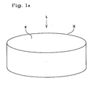
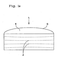
- a specified temperature control which is determined from the relation between the shape of the quartz glass and the cooling rate, i.e., the relation between the first temperature T 1 at the position located outward from the center of at least one surface of the upper and lower surfaces, which are the light transmitting surfaces of the columnar quartz glass (Fig. 1(a)), by a first distance and the second temperature T 2 at the position located outward from the outer peripheral side surface of the optical synthetic quartz glass preform by a second distance, there can be obtained, as shown in Fig. 1(b), an isothermal plane F inside the columnar quartz glass body G with a flat shape approximately in parallel with the light transmitting plane E.
- the quartz glass may be set inside the annealing furnace as such that the light transmitting direction is disposed in the longitudinal direction, or in the direction perpendicular thereto. Furthermore, the quartz glass may be set inside the annealing furnace in such a manner that it may be covered with a covering body such as a container and the like made of a quartz glass and the like.
- the temperature difference between the first temperature T 1 at the position parted outward from the center of at least one surface of the upper and lower surfaces and the second temperature T 2 at the position located outward from the outer peripheral side of said columnar quartz glass is preferably from 1 to 20°C, more preferably 1 to 15°C, and most preferably, 1 to 10°C.
- either of the first temperature T 1 and the second temperature T 2 can be set at a higher temperature; more specifically, there may be set as first temperature T 1 ⁇ second temperature T 2 , or as first temperature T 1 > second temperature T 2 .
- the temperature-lowering rate is more preferably 2 to 20°C/h, and most preferably, 2 to 10°C/h.
- the shape for the optical columnar synthetic quartz glass is preferably provided as a column having a diameter of from 150 to 350 mm and a thickness of from 40 to 120 mm.
- said first and the second distances they both are preferably the same and set in a range of from 5 mm to 100 mm.
- the first distance is set outward from at least one of the planes of the upper and the lower surfaces of the covering body, and the second parted distance is set outward from the outer peripheral side surface of said covering body.
- the first and the second distances may be set the same and in a range of from 5 mm to 100 mm.
- the first embodiment of the optical synthetic quartz glass according to the present invention is characterized in that it is produced by the production method according to the present invention, and that the synthtic quartz glass has a birefringence of the light transmitting direction of less than 0.5 nm/cm.
- the second embodiment of the optical synthetic quartz glass according to the present invention is characterized in that it is produced by the production method according to the present invention, and that the optical synthetic quartz glass has a refractive index distribution ⁇ n of the light transmitting direction of not higher than 2 ⁇ 10 -6 .
- the third embodiment of the optical synthetic quartz glass according to the present invention is characterized in that it is produced by the production method according to the present invention, and that the optical synthetic quartz glass has a birefringence of the light transmitting direction of lower than 0.5 nm/cm and a refractive index distribution ⁇ n of the light transmitting direction of not higher than 2 ⁇ 10 -6 .
- the annealing furnace according to the present invention is an annealing furnace for heat-treating a columnar optical synthetic quartz glass preform wherein the upper and lower surfaces are light transmitting surfaces, characterized by having a chamber adapted to contain the synthetic quartz glass preform in the inside thereof, a light transmitting surface heating heater configred to heat at least one of the upper and lower surfaces of the synthetic quartz glass, and a side surface heating heater configured to heat the outer peripheral side surface of the synthetic quartz glass, wherein the light transmitting surface heating heater and the side surface heating heater are controlled by separate temperature-controlling mechanisms.
- a chamber adapted to contain the synthetic quartz glass preform in the inside thereof, a light transmitting surface heating heater configred to heat at least one of the upper and lower surfaces of the synthetic quartz glass, and a side surface heating heater configured to heat the outer peripheral side surface of the synthetic quartz glass, wherein the light transmitting surface heating heater and the side surface heating heater are controlled by separate temperature-controlling mechanisms.
- a chamber adapted to contain the synthetic quartz glass preform in the inside
- Fig. 2 shows an oblique explanatory view of an example of an annealing furnace according to the present invention.
- the annealing furnace 10A comprises a cylindrical chamber 12.
- the cylindrical chamber 12 comprises a columnar base 14 provided therein.
- a columnar synthetic quartz glass G to be heat treated is mounted on the upper surface of said columnar base 14.
- a partition member 16 is provided on the upper side of said columnar synthetic quartz glass G inside said cylindrical chamber 12.
- 18a and 18b are thermocouples, wherein the upper surface side thermocouple 18a is set at a position P 1 apart outward by, e.g., 10 mm axially from the center of the upper plane of said columnar synthetic quartz glass by a first distance R 1 , and the side plane side thermocouple 18b is set at a position located outward from the outer peripheral side plane of said columnar synthetic quartz glass G by a second distance R 2 , at a position P 2 , radially apart from, e.g., 10 mm, so that they may each measure temperatures at positions P 1 and P 2 .
- a heater H1 for heating the upper surface (the light-transmitting surface) is provided on the upper side of said partition member 16.
- a ring-shaped heater H2 for heating the side plane is provided to the inner peripheral side plane of the cylindrical chamber 12.
- the temperature control of the upper surface side of the columnar synthetic quartz glass G mounted on a columnar base 14 can be made inside the partition member 16 by using the heater H1 for heating the upper surface (light transmitting surface), and the temperature control of the side plane side of said columnar synthetic quartz glass G can be made outside the partition member 16 by using the heater H2 for heating the side plane.
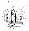
- Fig. 3 shows an oblique explanatory view of another example of an annealing furnace according to the present invention.
- a horizontal annealing furnace 10B Said annealing furnace 10B comprises a cylindrical chamber 12 set horizontally.
- a base plate 14 is set inside said cylindrical chamber 12.
- a first partition member 16a and a second partition member 16b are set on the upper surface of said base plate 14 in such a manner that they may face each other at a predetermined distance disposed between them, and that a mounting space 17 may be formed.
- the columnar synthetic quartz glass G to be heat treated is set in such a manner that it might be mounted on said base plate 14, and that it may be positioned in said mounting space 17.
- thermocouples 18a, 18a, and 18b are thermocouples, wherein the upper surface side thermocouples 18a and 18a are set at the position P 1 located axially outward from the center of the upper plane of at least one of the upper and lower surfaces of vertically set said columnar synthetic quartz glass by a first distance R 1 , for instance, at a position P 1 located at a distance of 10 mm, and the side plane side thermocouple 18b is set at a position P 2 located radially outward from the outer peripheral side plane of said columnar synthetic quartz glass G parted by a second distance R 2 , for instance, at a distance of 10 mm, so that they may each measure temperatures at positions P 1 and P2.
- Heaters H1 for heating the upper and the lower surfaces (light transmitting surfaces) are provided to each of said first and second partition members 16a and 16b, and on the other hand, a ring-like heater H2 for heating the side planes is provided on the inner peripheral side plane of the cylindrical chamber 12.
- the temperature control of the upper and the lower surface sides of the columnar synthetic quartz glass G mounted on the base plate 14 can be made inside the partition members 16a and 16b by using the heaters H1 for heating the upper and lower surfaces (light transmitting surfaces), and the temperature control of the side plane side of said columnar synthetic quartz glass G can be made outside the partition members 16a and 16b by using the heater H2 for heating the side plane.
- Fig. 4 shows an oblique explanatory view of another example of an annealing furnace according to the present invention.
- the same members or the members similar to those shown in Fig. 2 are indicated by using the same signs.
- the constitution is similar to that of the annealing furnace 10 shown in Fig. 2, except that the columnar synthetic quartz glass G to be heat treated is placed inside the annealing furnace 10C that is placed inside a covering body, which is a cylindrical container 20 provided with a quartz glass lid 19, and accordingly, thermocouple 18a is set axially outward from the center of the upper plane of said cylindrical container 20 by a first distance R 1 , for instance, at a position P 1 located at a distance of 10 mm.
- thermocouples 18a and 18b may each measure temperatures at each of the positions P 1 and P 2 , respectively. It is possible to separately control the temperatures of the upper and the lower surface and the outer peripheral side plane of the synthetic quartz glass G even in case the synthetic quartz glass is enclosed inside such a cylindrical container 20.
- Fig. 5 is a schematic explanatory diagram showing an example of a temperature-controlling mechanism.
- the annealing furnace 10A as shown in Fig. 2 is taken as an example of the annealing furnace. Similar to the case as shown in Fig. 2, the annealing furnace 10A is equipped with a cylindrical chamber 12, a columnar base 14, a partition member 16, and thermocouples 18a and 18b, wherein a columnar synthetic quartz glass G to be heat-treated is mounted on the columnar base 14.
- the upper surface thermocouple 18a is provided at a position P 1 set axially outward from the center of the upper plane of the columnar synthetic quartz glass G by a first distance R 1
- the side plane side thermocouple 18b is mounted at a position P 2 set radially outward from the outer peripheral side plane of the columnar synthetic quartz glass G by a second distance R 2 , to measure the temperatures at each of the positions P 1 and P 2 , respectively.
- a heater H1 for heating the upper surface (the light-transmitting surface) is provided on the upper side of said partition member 16, and a ring-shaped heater H2 for heating the side plane is provided on the inner peripheral side plane of the cylindrical chamber 12.
- the temperature T 1 at the position P 1 measured by said upper surface side thermocouple 18a is sent to a first comparative portion 21a, and is compared with the temperature T 3 previously input to the program.
- the compared data obtained on the temperatures T 1 and T 3 at the first comparative portion 21a is then sent to the first controlling portion 22a.
- the control signal generated from said first controlling portion 22a based on the compared data controls the heater H1 for heating the light transmitting surface (upper surface) to control the temperature of the upper surface side of the columnar synthetic quartz glass G. That is, the temperature-controlling mechanism A on the upper surface side is constructed by the upper surface side thermocouple 18a, the first comparative portion 21a, the first controlling portion 22a, and a heater H1 for heating the light transmitting surface.
- the temperature T 2 at the position P 2 measured by said side plane side thermocouple 18a is sent to a second comparative portion 21b, and is compared with the temperature T 4 previously input to the program.
- the compared data obtained on the temperatures T 2 and T 4 at the second comparative portion 21b is then sent to the first controlling portion 22b.
- the control signal generated from said second controlling portion 22b based on the compared data controls the heater H2 for heating the side plane side to control the temperature of the side plane side of the columnar synthetic quartz glass G. That is, the temperature-controlling mechanism B on the side plane side is constructed by the upper surface side thermocouple 18b, the second comparative portion 21b, the second controlling portion 22b, and a heater H2 for heating the side plane side.
- thermocouple 18a alone is provided as the thermocouple of the light transmitting surface side; however, as shown in Fig. 3, the heater for heating the light transmitting surface and the heater for heating the side plane may be controlled separately by individual temperature mechanisms even in case a lower surface side thermocouple is also provided.
- Birefringence Measurements were made by using an automatic birefringence measurement system (EXICOR 350AT, manufactured by HINDS Instruments, Inc.) equipped with a He-Ne laser (632.8 nm) as the light source.
- EXICOR 350AT automatic birefringence measurement system
- He-Ne laser 632.8 nm
- Refractive index distribution ⁇ n Measurements were made by using an interferometer (Mark GPlxp, manufactured by Zygo Corporation) equipped with a He-Ne laser (632.8 nm) as the light source.
- a synthetic quartz glass ingot 120 mm in outer diameter and 630 mm in length was produced by means of direct flame hydrolysis method comprising introducing gasified high purity methyl trimethoxysilane into an oxyhydrogen flame to generate soot-like silica, and melt-depositing the resulting product on a rotating base body.
- the both ends of the ingot thus obtained were welded to the support rods held by chucks of a lathe for processing quartz glass to rotate the synthetic quartz glass ingot.
- the rotating ingot was locally heated with a burner to form a molten band region, and stress was generated on the molten band region by independently changing the direction of rotation and the number of revolutions of the chuck. In this manner, striae removal and homogenization were performed on the ingot. Then, the distance between the chucks of the lathe for processing synthetic quartz glass quartz glass was narrowed to deform the synthetic quartz glass into a ball-like shape by applying pressure to the synthetic quartz glass, the ball-like synthetic quartz glass was cut off, and the synthetic quartz glass ingot was attached to the support rod of the support table in such a manner that the cut off planes were disposed to the upper and the lower planes. The synthetic quartz glass ingot was homogenized again by subjecting it to heating with a burner for softening. A rod-like synthetic quartz glass ingot was thus obtained.
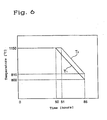
- the quartz glass member was held at 1150°C for 50 hours in accordance with the temperature program shown in Fig. 6. Then, the temperature of the upper surface side (at the first temperature T 1 ) was lowered at a rate of 10°C/h. After 1 hour from starting the lowering of temperature, the temperature of the outer peripheral side plane side (at a second temperature of T 2 ) was lowered at a rate of 10°C/h, and the quartz member was subjected to natural cooling from the point the temperature indicated by the thermocouple set on the upper surface side reached 800°C.
- the optical properties of the synthetic quartz glass member was investigated, and a graph showing the relation between the distance from the center of the light transmitting surface and the value of birefringence was obtained as shown in Fig. 8, wherein the line with black squares represents the measurement of example 1, the diamond-tracked line represents comparative example 1.
- the maximum value of birefringence in the light transmitting direction was found to be 0.25 nm/cm.
- a refractive index distribution ⁇ n of 1.5 ⁇ 10 -6 was obtained.
- a quartz glass member shaped in accordance with the procedure similar to that described in Example 1 was placed vertically inside an annealing furnace having the structure similar to that shown in Fig. 3. Heat treatment was applied to the quartz glass member in an operation similar to that described in Example 1 to obtain a synthetic quartz member.
- a maximum birefringence value in the light transmitting direction of 0.24 nm/cm and a refractive index distribution ⁇ n of 1.2 ⁇ 10 -6 were obtained.
- thermocouples for temperature control were set at a position parted outward from the center of the upper surface of the cylindrical container by 10 mm, and at a position parted outward from the outer peripheral surface of the container by 10 mm.
- the synthetic quartz member was produced in a manner similar to that described in Example 1, except that the temperature of the upper surface side of the container was lowered at a rate of 20°C/h after holding at a temperature of 1150°C for 50 hours, that the temperature lowering of the outer peripheral surface side was started at a rate of 20°C/h 30 minutes thereafter, and that the container was left for natural cooling at the point the temperature reached 800°C.
- a maximum birefringence value in the light transmitting direction of 0.22 nm/cm and a refractive index distribution ⁇ n of 1.0 ⁇ 10 -6 were obtained.
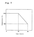
- a synthetic quartz member was produced in a procedure similar to that described in Example 1, except that the temperature of the quartz glass member set inside the annealing furnace was lowered at a rate of 10°C/h in accordance with the temperature program shown in Fig. 7 after holding the member at 1150°C for 50 hours without using separate temperature control mechanisms, and that the member was left for natural cooling at the point temperature reached 800°C.
- the optical properties of the synthetic quartz glass member was investigated, and a graph showing the relation between the distance from the center of the light transmitting surface and the value of birefringence was obtained as shown in Fig. 8 (diamond-tracked line). Referring to Fig. 8, the maximum value of birefringence in the light transmitting direction was found to be 2.4 nm/cm. A refractive index distribution ⁇ n of 2.3 ⁇ 10 -6 was obtained.
- Example 1 As in Example 1, after holding the quartz glass member set inside the annealing furnace at 1150°C for 50 hours, the temperature of the upper surface side was lowered at a rate of 10°C/h. The same procedure as that described in Example 1 was followed, except that, after 3 hours since starting cooling of the upper surface side, the outer peripheral side was cooled at a rate of 10°C/h, and that the member was left for natural cooling from the point indicated temperature reached 800°C. On examining the optical properties of the synthetic quartz glass member, a maximum birefringence value in the light transmitting direction of 2.0 nm/cm and a refractive index distribution ⁇ n of 3.4 ⁇ 10 -6 were obtained.
- Example 1 As in Example 1, after holding the quartz glass member set inside the annealing furnace at 1150°C for 50 hours, the temperature of the upper surface side was first lowered at a rate of 80°C/h. The same procedure as that described in Example 1 was followed, except that, after 3 minutes since starting cooling of the upper surface side, the outer peripheral side was left for natural cooling from the point indicated temperature reached 800°C. On examining the optical properties of the synthetic quartz glass member, a maximum birefringence value in the light transmitting direction of 1.8 nm/cm and a refractive index distribution ⁇ n of 3.7 ⁇ 10 -6 were obtained.
- the method according to the present invention enables achieving a great effect of producing an optical quartz glass having a birefringence in the light transmitting direction of lower than 0.5 nm/cm and having favorable refractive index distribution.
Landscapes
- Chemical & Material Sciences (AREA)
- Engineering & Computer Science (AREA)
- Materials Engineering (AREA)
- Organic Chemistry (AREA)
- Physics & Mathematics (AREA)
- Thermal Sciences (AREA)
- Chemical Kinetics & Catalysis (AREA)
- Life Sciences & Earth Sciences (AREA)
- General Chemical & Material Sciences (AREA)
- Geochemistry & Mineralogy (AREA)
- Manufacturing & Machinery (AREA)
- Glass Melting And Manufacturing (AREA)
Abstract
Description
As said first and the second distances, they both are preferably the same and set in a range of from 5 mm to 100 mm. In case quartz glass is covered with a covering body such as a container and the like, the first distance is set outward from at least one of the planes of the upper and the lower surfaces of the covering body, and the second parted distance is set outward from the outer peripheral side surface of said covering body. In this case again, the first and the second distances may be set the same and in a range of from 5 mm to 100 mm.
- Fig. 1
- is a view explaining an embodiment of the optical synthetic quartz glass of the invention, wherein (a) is a slant view of the whole embodiment, and (b) is a cross-sectional view of (a).
- Fig. 2
- is a schematic explanatory slant view showing an embodiment of the annealing furnace used for the practice of the production method of an optical synthetic glass of the invention.
- Fig. 3
- is a schematic explanatory slant view showing another embodiment of the annealing furnace used for the practice of the production method of an optical synthetic glass of the invention.
- Fig. 4
- is a schematic explanatory slant view showing still another embodiment of the annealing furnace used for the practice of the production method of an optical synthetic glass of the invention.
- Fig. 5
- is a schematic explanatory view showing an embodiment of the temperature-controlling mechanism in an annealing furnace.
- Fig. 6
- is a graph showing the relation between the temperature and the time in the heat treatment in Example 1.
- Fig. 7
- is a graph showing the relation between the temperature and the time in the heat treatment in Comparative Example 1.
- Fig. 8
- is a graph showing the relation between the distance from the center of the light transmitting surface of the synthetic quartz glass member of the heat treatment line and the value of the double refraction of the light transmitting direction in Example 1.
- Fig. 9
- is an explanatory view showing an embodiment of an optical synthetic quartz glass of related art, wherein (a) is a slant view of the whole embodiment and (b) is a cross-sectional view of (a).
Claims (11)
- A method of producing an optical synthetic quartz glass, characterized in that in a step of raising the temperature of a columnar optical synthetic quartz glass preform (G) to a temperature of from 800°C to 1200°C, and after keeping the temperature of the synthetic quartz glass preform in said range for a definite time, lowering the temperature, the temperature is lowered with a temperature difference of from 1 to 20°C between the temperature of a light transmitting surface (E) of the optical synthetic quartz glass preform and the temperature of an outer peripheral side surface of the optical synthetic quartz glass preform with temperature-lowering rates of from 2 to 50°C/hour, respectively.
- A method of producing an optical synthetic quartz glass, characterized in that in a step of raising the temperature of a columnar optical synthetic quartz glass preform (G) to a temperature in a range of from 800°C to 1200°C, and after keeping the temperature for a definite time, lowering the temperature, the temperature being lowered with a temperature difference of from 1 to 20°C between a first temperature T1 at the position located outward from a center of at least one of an upper and a lower surface, said surfaces being light transmitting surfaces (E) of the optical synthetic quartz glass preform, by a first distance and a second temperature T2 at a position located outward from an outer peripheral side surface of the optical synthetic quartz glass preform by a second distance, at temperature-lowering rates of from 2 to 50°C/hour, respectively.
- The method of producing an optical synthetic quartz glass described in claim 2, wherein both the first distance (R1) and the second distance (R2) are from 5 mm to 100 mm.
- The method of producing an optical synthetic quartz glass described in claim 2 or 3, wherein in the temperature-lowering step, the first temperature T1 is lower than the second temperature T2.
- The method of producing an optical synthetic quartz glass described in claim 2 or 3, wherein in the temperature-lowering step, the first temperature T1 is higher than the second temperature T2.
- The method of producing an optical synthetic quartz glass described in one of claims 2 to 5, wherein in the step of temperature lowering, separate temperature-controlling mechanisms (A; B) are used for a surface parallel to the light transmitting surface (E) and the surface perpendicular to the light transmitting surface.
- The method of producing an optical synthetic quartz glass described in one of claims 1 to 6, wherein the above-described optical synthetic quartz glass preform (G) is a columnar form having a diameter of from 150 to 350 mm and a thickness of from 40 to 120 mm.
- An optical synthesis quartz glass produced by the production method described in one of claims 1 to 7, characterized in that the synthetic quartz glass preform has a birefringence in the light transmitting direction that is lower than 0.5 nm/cm.
- An optical synthesis quartz glass produced by the production method described in one of claims 1 to 8, characterized in that the synthetic quartz glass preform has a refractive index distribution, Δn, in the light transmitting direction that is not higher than 2 × 10⁻⁶.
- An optical synthesis quartz glass produced by the production method described in one of claims 1 to 9, characterized in that the synthetic quartz glass preform has a birefringence in the light transmitting direction that is lower than 0.5 nm/cm and the refractive index distribution, Δn, that is not higher than 2 × 10⁻⁶.
- An annealing furnace (10A; 10B; 10C) for heat-treating a columnar optical synthetic quartz glass preform (G) wherein the upper and lower surfaces are light transmitting surfaces (E), characterized by having a chamber (12) adapted to contain the synthetic quartz glass preform in the inside thereof, a light transmitting surface heating heater (H1) configured to heat at least one of the upper and lower surfaces of the synthetic quartz glass in the chamber (12), and a side surface heating heater (H2) configured to heat the outer peripheral side surface of the synthetic quartz glass, wherein the light transmitting surface heating heater (H1) and the side surface heating heater (H2) are controlled by separate temperature-controlling mechanisms (A; B).
Applications Claiming Priority (2)
| Application Number | Priority Date | Filing Date | Title |
|---|---|---|---|
| JP2001384505 | 2001-12-18 | ||
| JP2001384505A JP4017863B2 (en) | 2001-12-18 | 2001-12-18 | Annealing furnace and method for producing optical synthetic quartz glass |
Publications (3)
| Publication Number | Publication Date |
|---|---|
| EP1321439A2 true EP1321439A2 (en) | 2003-06-25 |
| EP1321439A3 EP1321439A3 (en) | 2004-03-31 |
| EP1321439B1 EP1321439B1 (en) | 2006-02-22 |
Family
ID=19187729
Family Applications (1)
| Application Number | Title | Priority Date | Filing Date |
|---|---|---|---|
| EP02028278A Expired - Lifetime EP1321439B1 (en) | 2001-12-18 | 2002-12-17 | Method and furnace for producing an optical quartz glass |
Country Status (4)
| Country | Link |
|---|---|
| US (1) | US7111477B2 (en) |
| EP (1) | EP1321439B1 (en) |
| JP (1) | JP4017863B2 (en) |
| DE (1) | DE60209293T2 (en) |
Families Citing this family (6)
| Publication number | Priority date | Publication date | Assignee | Title |
|---|---|---|---|---|
| JP5418428B2 (en) * | 2010-07-15 | 2014-02-19 | 信越化学工業株式会社 | Heat treatment method for synthetic quartz glass block |
| US20150239767A1 (en) * | 2014-02-26 | 2015-08-27 | Corning Incorporated | HEAT TREATING SILICA-TITANIA GLASS TO INDUCE A Tzc GRADIENT |
| JP6830855B2 (en) * | 2017-04-24 | 2021-02-17 | 信越石英株式会社 | Manufacturing method of synthetic quartz glass |
| EP3643687B1 (en) * | 2018-10-26 | 2022-11-30 | Heraeus Quarzglas GmbH & Co. KG | Method and device for homogenisation of glass |
| EP3643688B1 (en) | 2018-10-26 | 2022-12-14 | Heraeus Quarzglas GmbH & Co. KG | Method for homogenising glass |
| CN118005022B (en) * | 2024-02-02 | 2024-11-19 | 凤阳昌荣粉体材料有限公司 | Automatic quartz sand processing method and system |
Family Cites Families (16)
| Publication number | Priority date | Publication date | Assignee | Title |
|---|---|---|---|---|
| US2106526A (en) * | 1935-02-19 | 1938-01-25 | Corning Glass Works | Low expansion annealed glass |
| DE10010484A1 (en) * | 2000-03-03 | 2001-09-13 | Schott Glas | Device for growing large volume single crystals has heating element arranged on side walls of melt crucible to prevent lateral radial heat flow |
| US4149868A (en) * | 1978-02-24 | 1979-04-17 | American Optical Corporation | Process for producing opthalmic lenses with gradated photochromic behavior |
| US5325230A (en) * | 1989-06-09 | 1994-06-28 | Shin-Etsu Quartz Products Co., Ltd. | Optical members and blanks of synthetic silica glass and method for their production |
| JP2835542B2 (en) * | 1991-07-31 | 1998-12-14 | 信越石英株式会社 | Heat treatment method for synthetic quartz glass molded article for optical |
| JP2835543B2 (en) * | 1991-07-31 | 1998-12-14 | 信越石英株式会社 | Heat treatment method for synthetic quartz glass molded article for optical |
| EP0870737B1 (en) | 1997-04-08 | 2002-07-24 | Shin-Etsu Quartz Products Co., Ltd. | Optical synthetic quartz glass, production method thereof, and optical member for excimer laser using the synthetic quartz glass |
| JP4011217B2 (en) | 1998-12-25 | 2007-11-21 | 信越石英株式会社 | Manufacturing method of optical quartz glass for excimer laser |
| JP4601022B2 (en) | 1999-03-04 | 2010-12-22 | 信越石英株式会社 | Synthetic quartz glass member for ArF excimer laser lithography |
| JP2001019465A (en) | 1999-07-07 | 2001-01-23 | Shin Etsu Chem Co Ltd | Synthetic quartz glass member for excimer laser and method of manufacturing the same |
| JP4453939B2 (en) | 1999-09-16 | 2010-04-21 | 信越石英株式会社 | Optical silica glass member for F2 excimer laser transmission and manufacturing method thereof |
| JP4466979B2 (en) * | 2000-02-01 | 2010-05-26 | 信越石英株式会社 | Highly homogeneous synthetic quartz glass for optics and method for producing the same |
| JP4439072B2 (en) * | 2000-03-29 | 2010-03-24 | 信越石英株式会社 | Synthetic quartz glass for optics, heat treatment method and heat treatment apparatus thereof |
| US6578382B2 (en) * | 2000-03-29 | 2003-06-17 | Heraeus Quarzglas Gmbh & Co. Kg | Synthetic quartz glass for optical use, heat treatment method and heat treatment apparatus for the same |
| US20020122902A1 (en) * | 2000-11-30 | 2002-09-05 | Tetsuji Ueda | Blank for an optical member as well as vessel and method of producing the same |
| US20050092231A1 (en) * | 2003-10-29 | 2005-05-05 | Hawtof Daniel W. | Method and apparatus for making crystals without a pre-melt step |
-
2001
- 2001-12-18 JP JP2001384505A patent/JP4017863B2/en not_active Expired - Fee Related
-
2002
- 2002-12-16 US US10/320,338 patent/US7111477B2/en not_active Expired - Lifetime
- 2002-12-17 EP EP02028278A patent/EP1321439B1/en not_active Expired - Lifetime
- 2002-12-17 DE DE60209293T patent/DE60209293T2/en not_active Expired - Lifetime
Also Published As
| Publication number | Publication date |
|---|---|
| DE60209293T2 (en) | 2006-10-19 |
| US7111477B2 (en) | 2006-09-26 |
| JP2003183036A (en) | 2003-07-03 |
| DE60209293D1 (en) | 2006-04-27 |
| JP4017863B2 (en) | 2007-12-05 |
| EP1321439A3 (en) | 2004-03-31 |
| US20030228119A1 (en) | 2003-12-11 |
| EP1321439B1 (en) | 2006-02-22 |
Similar Documents
| Publication | Publication Date | Title |
|---|---|---|
| EP0917523B1 (en) | Synthetic silica glass used with uv-rays and method producing the same | |
| JP3064857B2 (en) | Optical member for optical lithography and method for producing synthetic quartz glass | |
| EP1084995B1 (en) | Optical member of silica glass for transmitting fluorine excimer laser radiation and method for producing the same | |
| JP2862001B2 (en) | Manufacturing method of quartz glass optical member | |
| EP1033350B1 (en) | Synthetic quartz glass member for use in ArF excimer laser lithography | |
| US7312170B2 (en) | Optical synthetic quartz glass and method for producing the same | |
| KR20030047753A (en) | Quartz glass blank for an optical component, and manufacturing procedure and use thereof | |
| EP1321439B1 (en) | Method and furnace for producing an optical quartz glass | |
| JP2588447B2 (en) | Method of manufacturing quartz glass member for excimer laser | |
| US6508084B1 (en) | Method for producing optical quartz glass for excimer lasers and vertical-type heating furnace | |
| CN101426740A (en) | Manufacture of large articles in synthetic vitreous silica | |
| JP2861512B2 (en) | Manufacturing method of quartz glass optical member | |
| US6266978B1 (en) | Method for producing synthetic quartz glass for use in ArF excimer laser lithography | |
| WO2000039038A1 (en) | Method for producing optical quartz glass for excimer lasers | |
| JPH0616449A (en) | Synthetic quartz glass optical member for excimer laser and manufacturing method thereof | |
| JP2814795B2 (en) | Manufacturing method of quartz glass | |
| JP2007261942A (en) | Synthetic quartz glass for optics | |
| JPH06166527A (en) | Quartz glass manufacturing method | |
| JP2835540B2 (en) | Method of manufacturing quartz glass member for excimer laser | |
| JP2003238195A (en) | Synthetic quartz glass | |
| JP2003176143A (en) | Synthetic quartz glass member | |
| JPH0952723A (en) | Optical synthetic quartz glass material and method for producing the same | |
| JPH07247132A (en) | Quartz glass manufacturing method | |
| JP4177078B2 (en) | Synthetic quartz glass material for optical components | |
| JP5208677B2 (en) | Method for producing synthetic quartz glass member for ArF excimer laser lithography |
Legal Events
| Date | Code | Title | Description |
|---|---|---|---|
| PUAI | Public reference made under article 153(3) epc to a published international application that has entered the european phase |
Free format text: ORIGINAL CODE: 0009012 |
|
| 17P | Request for examination filed |
Effective date: 20030109 |
|
| AK | Designated contracting states |
Designated state(s): AT BE BG CH CY CZ DE DK EE ES FI FR GB GR IE IT LI LU MC NL PT SE SI SK TR |
|
| AX | Request for extension of the european patent |
Extension state: AL LT LV MK RO |
|
| PUAL | Search report despatched |
Free format text: ORIGINAL CODE: 0009013 |
|
| AK | Designated contracting states |
Kind code of ref document: A3 Designated state(s): AT BE BG CH CY CZ DE DK EE ES FI FR GB GR IE IT LI LU MC NL PT SE SI SK TR |
|
| AX | Request for extension of the european patent |
Extension state: AL LT LV MK RO |
|
| RIC1 | Information provided on ipc code assigned before grant |
Ipc: 7C 03B 32/00 A Ipc: 7C 03C 3/06 B Ipc: 7C 03B 19/14 B |
|
| 17Q | First examination report despatched |
Effective date: 20040806 |
|
| AKX | Designation fees paid |
Designated state(s): AT DE FR GB NL |
|
| GRAP | Despatch of communication of intention to grant a patent |
Free format text: ORIGINAL CODE: EPIDOSNIGR1 |
|
| RTI1 | Title (correction) |
Free format text: METHOD AND FURNACE FOR PRODUCING AN OPTICAL QUARTZ GLASS |
|
| GRAS | Grant fee paid |
Free format text: ORIGINAL CODE: EPIDOSNIGR3 |
|
| GRAA | (expected) grant |
Free format text: ORIGINAL CODE: 0009210 |
|
| AK | Designated contracting states |
Kind code of ref document: B1 Designated state(s): DE NL |
|
| REF | Corresponds to: |
Ref document number: 60209293 Country of ref document: DE Date of ref document: 20060427 Kind code of ref document: P |
|
| PLBE | No opposition filed within time limit |
Free format text: ORIGINAL CODE: 0009261 |
|
| STAA | Information on the status of an ep patent application or granted ep patent |
Free format text: STATUS: NO OPPOSITION FILED WITHIN TIME LIMIT |
|
| 26N | No opposition filed |
Effective date: 20061123 |
|
| PGFP | Annual fee paid to national office [announced via postgrant information from national office to epo] |
Ref country code: NL Payment date: 20081216 Year of fee payment: 7 |
|
| REG | Reference to a national code |
Ref country code: NL Ref legal event code: V1 Effective date: 20100701 |
|
| PG25 | Lapsed in a contracting state [announced via postgrant information from national office to epo] |
Ref country code: NL Free format text: LAPSE BECAUSE OF NON-PAYMENT OF DUE FEES Effective date: 20100701 |
|
| REG | Reference to a national code |
Ref country code: DE Ref legal event code: R082 Ref document number: 60209293 Country of ref document: DE Representative=s name: BRAND, NORMEN, DR. RER. NAT., DE Ref country code: DE Ref legal event code: R082 Ref document number: 60209293 Country of ref document: DE Representative=s name: BRAND, NORMEN, DIPL.-CHEM. UNIV. DR. RER. NAT., DE Ref country code: DE Ref legal event code: R082 Ref document number: 60209293 Country of ref document: DE Representative=s name: EULER, MATTHIAS, DR., DE |
|
| REG | Reference to a national code |
Ref country code: DE Ref legal event code: R082 Ref document number: 60209293 Country of ref document: DE Representative=s name: BRAND, NORMEN, DR. RER. NAT., DE Ref country code: DE Ref legal event code: R082 Ref document number: 60209293 Country of ref document: DE Representative=s name: BRAND, NORMEN, DIPL.-CHEM. UNIV. DR. RER. NAT., DE |
|
| PGFP | Annual fee paid to national office [announced via postgrant information from national office to epo] |
Ref country code: DE Payment date: 20211210 Year of fee payment: 20 |
|
| REG | Reference to a national code |
Ref country code: DE Ref legal event code: R071 Ref document number: 60209293 Country of ref document: DE |