EP1321340A1 - Parking brake device of working vehicle - Google Patents
Parking brake device of working vehicle Download PDFInfo
- Publication number
- EP1321340A1 EP1321340A1 EP01963560A EP01963560A EP1321340A1 EP 1321340 A1 EP1321340 A1 EP 1321340A1 EP 01963560 A EP01963560 A EP 01963560A EP 01963560 A EP01963560 A EP 01963560A EP 1321340 A1 EP1321340 A1 EP 1321340A1
- Authority
- EP
- European Patent Office
- Prior art keywords
- brake
- release
- clutch device
- parking brake
- pressure
- Prior art date
- Legal status (The legal status is an assumption and is not a legal conclusion. Google has not performed a legal analysis and makes no representation as to the accuracy of the status listed.)
- Granted
Links
- 230000005540 biological transmission Effects 0.000 claims abstract description 57
- 230000004044 response Effects 0.000 claims description 19
- 230000002265 prevention Effects 0.000 claims description 6
- 238000010586 diagram Methods 0.000 description 6
- 238000011144 upstream manufacturing Methods 0.000 description 5
- 230000005611 electricity Effects 0.000 description 4
- 230000007246 mechanism Effects 0.000 description 2
- 230000009467 reduction Effects 0.000 description 2
- 239000007858 starting material Substances 0.000 description 2
- 230000008859 change Effects 0.000 description 1
- 230000001276 controlling effect Effects 0.000 description 1
- 230000001934 delay Effects 0.000 description 1
- 230000004048 modification Effects 0.000 description 1
- 238000012986 modification Methods 0.000 description 1
- 230000007935 neutral effect Effects 0.000 description 1
- 230000001105 regulatory effect Effects 0.000 description 1
Images

Classifications
-
- B—PERFORMING OPERATIONS; TRANSPORTING
- B60—VEHICLES IN GENERAL
- B60T—VEHICLE BRAKE CONTROL SYSTEMS OR PARTS THEREOF; BRAKE CONTROL SYSTEMS OR PARTS THEREOF, IN GENERAL; ARRANGEMENT OF BRAKING ELEMENTS ON VEHICLES IN GENERAL; PORTABLE DEVICES FOR PREVENTING UNWANTED MOVEMENT OF VEHICLES; VEHICLE MODIFICATIONS TO FACILITATE COOLING OF BRAKES
- B60T13/00—Transmitting braking action from initiating means to ultimate brake actuator with power assistance or drive; Brake systems incorporating such transmitting means, e.g. air-pressure brake systems
- B60T13/10—Transmitting braking action from initiating means to ultimate brake actuator with power assistance or drive; Brake systems incorporating such transmitting means, e.g. air-pressure brake systems with fluid assistance, drive, or release
- B60T13/12—Transmitting braking action from initiating means to ultimate brake actuator with power assistance or drive; Brake systems incorporating such transmitting means, e.g. air-pressure brake systems with fluid assistance, drive, or release the fluid being liquid
- B60T13/22—Brakes applied by springs or weights and released hydraulically
-
- B—PERFORMING OPERATIONS; TRANSPORTING
- B60—VEHICLES IN GENERAL
- B60T—VEHICLE BRAKE CONTROL SYSTEMS OR PARTS THEREOF; BRAKE CONTROL SYSTEMS OR PARTS THEREOF, IN GENERAL; ARRANGEMENT OF BRAKING ELEMENTS ON VEHICLES IN GENERAL; PORTABLE DEVICES FOR PREVENTING UNWANTED MOVEMENT OF VEHICLES; VEHICLE MODIFICATIONS TO FACILITATE COOLING OF BRAKES
- B60T13/00—Transmitting braking action from initiating means to ultimate brake actuator with power assistance or drive; Brake systems incorporating such transmitting means, e.g. air-pressure brake systems
- B60T13/10—Transmitting braking action from initiating means to ultimate brake actuator with power assistance or drive; Brake systems incorporating such transmitting means, e.g. air-pressure brake systems with fluid assistance, drive, or release
- B60T13/66—Electrical control in fluid-pressure brake systems
- B60T13/68—Electrical control in fluid-pressure brake systems by electrically-controlled valves
- B60T13/686—Electrical control in fluid-pressure brake systems by electrically-controlled valves in hydraulic systems or parts thereof
-
- B—PERFORMING OPERATIONS; TRANSPORTING
- B60—VEHICLES IN GENERAL
- B60T—VEHICLE BRAKE CONTROL SYSTEMS OR PARTS THEREOF; BRAKE CONTROL SYSTEMS OR PARTS THEREOF, IN GENERAL; ARRANGEMENT OF BRAKING ELEMENTS ON VEHICLES IN GENERAL; PORTABLE DEVICES FOR PREVENTING UNWANTED MOVEMENT OF VEHICLES; VEHICLE MODIFICATIONS TO FACILITATE COOLING OF BRAKES
- B60T7/00—Brake-action initiating means
- B60T7/02—Brake-action initiating means for personal initiation
-
- F—MECHANICAL ENGINEERING; LIGHTING; HEATING; WEAPONS; BLASTING
- F16—ENGINEERING ELEMENTS AND UNITS; GENERAL MEASURES FOR PRODUCING AND MAINTAINING EFFECTIVE FUNCTIONING OF MACHINES OR INSTALLATIONS; THERMAL INSULATION IN GENERAL
- F16H—GEARING
- F16H61/00—Control functions within control units of change-speed- or reversing-gearings for conveying rotary motion ; Control of exclusively fluid gearing, friction gearing, gearings with endless flexible members or other particular types of gearing
- F16H61/38—Control of exclusively fluid gearing
- F16H61/40—Control of exclusively fluid gearing hydrostatic
Definitions
- the present invention relates to a parking brake unit for a work vehicle having a parking brake operated when the engine is stopped.
- a negative parking brake has been provided in a work vehicle such as a wheeled hydraulic excavator or a wheel loader, in addition to a foot brake. Operation of this parking brake is released if release pressure is supplied from a hydraulic source after an engine has been started, and the parking brake is operated if supply of the release pressure is stopped when the engine is stopped.
- the vehicle In the case where an engine can not be started, such as because of vehicle failure etc., the vehicle shall be towed to a specified location. In this case, if the parking brake is kept operating, it becomes difficult to tow the vehicle away. For this reason, it is necessary to allow the parking brake to be released even if the engine is stopped.
- the parking brake is released by operating a release lever or the like at outside of the operator's cabin, which is provided close to the parking brake. However, it is troublesome to release the parking brake manually at outside of the operator's cabin. Also, in the case where the release lever for the parking brake is provided at a place hidden from the view, operability is degraded.
- the object of the present invention is to provide a parking brake unit for a work vehicle that releases a parking brake easily with an operation inside the operator's cabin, even when the engine is stopped.
- a parking brake unit for a work vehicle comprises a hydraulic source; a negative parking brake provided a lower portion of the vehicle, that releases brake operation in response to brake release pressure; an operating member that outputs a release command for the parking brake in response to operation performed in an operator's cabin; and a brake release means for releasing operation of the parking brake by leading the brake release pressure to the parking brake if the release command is output.
- the brake release means comprises a brake release accumulator that accumulates pressure oil from the hydraulic source, and a control valve that allows the pressure oil accumulated in the accumulator to act on the parking brake as the brake release pressure if the release command is output.
- the parking brake is constituted by a transmission having a negative first clutch device and a negative second clutch device.
- the transmission sets a first gear ratio by allowing a propeller shaft to rotate if the first clutch device is released by control pressure for clutch release, and sets a second gear ratio smaller than the first gear ratio by allowing the propeller shaft to rotate if the second clutch device is released by the control pressure for clutch release.
- the control valve allows the pressure oil from the accumulator to act on the second clutch device as the brake release pressure if the release command is output.
- the control valve may allow the pressure oil from the accumulator to act on the first clutch device as the brake release pressure if the release command is output.
- the control valve may also allow the pressure oil from the accumulator to act on one of the first clutch device and the second clutch device as the brake release pressure if the release command is output.
- a transmission control means having a gear ratio control valve that controls flow of the control pressure for clutch release for acting on the first clutch device and the second clutch device, and a sudden operation prevention accumulator that prevents sudden operation of the parking brake, and the brake release means may be provided between the parking brake and the transmission control means.
- the brake release means further comprises a prevention means for preventing the pressure oil accumulated in the accumulator flowing out to the hydraulic power side.
- the foot brake accumulator may also function as the brake release accumulator.
- a parking brake unit for a work vehicle comprises a hydraulic source; a negative parking brake provided a lower portion of the vehicle, that releases brake operation in response to brake release pressure; an operating member that outputs a release command for the parking brake in response to operation performed in an operator's cabin; and a brake release means for releasing operation of the parking brake by leading the brake release pressure to the parking brake if the release command is output.
- the parking brake is constituted of a transmission having a negative first clutch device and a negative second clutch device.
- the transmission sets a first gear ratio by allowing a propeller shaft to rotate if the first clutch device is released by control pressure for clutch release, and sets a second gear ratio smaller than the first gear ratio by allowing the propeller shaft to rotate if the second clutch device is released by the control pressure for clutch release.
- the brake release means comprises a brake release accumulator that accumulates pressure oil from the hydraulic source, and a control valve that allows the pressure oil accumulated in the accumulator to be guided to the second clutch device as the brake release pressure if the release command is output.
- the brake release means allows the oil accumulated in the accumulator to flow, and leads the brake release pressure to the parking brake. Therefore, even if the engine is stopped, it is possible to release the parking brake through the operation in the operator's cabin.
- the brake release means is provided between the parking brake and the transmission control means. As a result, since the pressure oil does not flow from the brake release means to the transmission control means, it is possible to minimize the brake release accumulator.
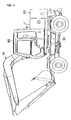
- Fig. 4 is a side elevation of a wheeled hydraulic excavator.
- the wheeled hydraulic excavator comprises an undercarriage 81, and an upper structure 83 connected to an upper part of the undercarriage 81 via a swing device 82 so as to be capable of revolving.
- a front attachment 84 for working and an operator' s cabin 85 are provided on the upper structure 83.
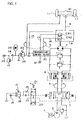
- Fig. 1 is a hydraulic circuit diagram for traveling adapted in a wheeled hydraulic excavator to which the present invention is applied.
- direction and flow amount of delivery oil from a main pump 2 driven by an engine (prime mover) 1 are respectively controlled by a control valve 3.
- Pressure oil whose direction and flow amount have been controlled passes through a center joint 5 and is supplied to a travel motor 7 via a counter balance valve 6.
- the rotation speed of the travel motor 7 is varied by a transmission 8, and transmitted via a propeller shaft 9 and axle 10 to tires 11. In this way, the wheeled hydraulic excavator travels.
- the transmission 8 is a well-known device having a planetary reduction mechanism, and clutch devices CR1 and CR2.
- the planetary reduction mechanism comprises a sun gear, a planetary gear and a ring gear, with the clutch devices CR1 and CR2 being provided at the sun gear side and the ring gear side, respectively.
- Each of the clutch devices CR1 and CR2 is put into engaged states by force of a spring.
- the clutch devices CR1 and CR2 are set to released states using hydraulic pressure from the hydraulic source 12 acting against the spring force. Hydraulic pressure acting on the clutch devices CR1 and CR2 is controlled in accordance with operation of the transmission control valve 30.
- both clutch devices CR1 and CR2 are set to the engaged state by the spring force.
- the transmission 8 is locked and rotation of the propeller shaft 9 is prevented.
- prevention of rotation of the propeller shaft 9 achieved by locking the transmission 8 is used as a parking brake. That is, the transmission 8 is a spring applied hydraulic release parking brake or a negative parking brake that is released if the release pressure is supplied from the hydraulic source, and operated if supply of the release pressure is stopped.
- a pilot circuit for traveling comprises a pilot hydraulic source 16, a travel pilot valve 18, a slow-return valve 19, and a forward and reverse switching valve 20.
- the pilot hydraulic source 16 similarly to the main pump 2, is driven by the engine (prime mover) 1 to generate pressure oil.
- the travel pilot valve 18 generates pilot secondary pressure in response to depression of the accelerator pedal 17.
- the slow-return valve 19 is connected with the pilot valve 18 and delays the oil returning to the pilot valve 18.
- the forward and reverse switching valve 20 is connected with the slow return valve 19 and is switched by an operating lever 21 to select forward, reverse or neutral of the vehicle travel.
- Pilot pressure from the pilot hydraulic source 16 acts on the pilot port of the control valve 3 to drive the control valve 3.
- Vehicle travel speed can be adjusted by varying the stroke amount of the control valve 3 using the accelerator pedal 17.
- a well-known foot brake is provided in the wheeled hydraulic excavator, which exerts deceleration force in response to operation of a brake pedal 22.
- a pilot circuit for this foot brake comprises a pilot hydraulic source 23 driven by the engine (prime mover) 1, similarly to the main pump 2, to generate pressure oil, a check valve 24, and a brake valve 25 for generating pilot secondary pressure in response to depression of the brake pedal 22.
- An accumulator 26 for accumulating specified pressure oil is also provided between the check valve 24 and the brake valve 25.
- Specified pressure from the hydraulic source 23 driven by the engine (prime mover) 1 is accumulated in the accumulator 26. Even if the hydraulic source 23 stops supplying pressure oil because the engine is stopped etc., pressure oil is accumulated in the accumulator 26. Therefore, it is possible to cause the foot brake to be driven by operation of the pedal 22 for only a specified time using the pressure oil accumulated in the accumulator 26.
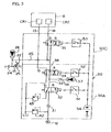
- Fig. 2 is a hydraulic circuit diagram showing the structure of the transmission control valve 30.
- the transmission control valve 30 has a transmission control unit 30A for controlling drive of the transmission 8 and a brake release unit 30B for releasing the parking brake when the engine is stopped.
- Pressure oil from the hydraulic power source 12 is guided through a check valve 31 to a solenoid switching valve 32.
- Pressure oil passing through the solenoid switching valve 32 is guided to a solenoid switching valve 34 (gear ratio control valve) through a pipeline 33.
- Pressure oil passing through the solenoid switching valve 34 is guided to the clutch device CR1 via a pipeline 13 or to the clutch device CR2 via a solenoid switching valve 35 (control valve) and a pipeline 14.
- An accumulator 37 is connected to the pipeline 33 via a restrictor 36.
- a pipeline connected to the solenoid switching valve 34 and going towards the solenoid switching valve 35 branches into two.
- One pipeline 38 is connected directly to the solenoid switching valve 35, while the other pipeline 39 is connected to the solenoid switching valve 35 via a check valve 40.
- An accumulator 41 is connected to the pipeline 39 between the check valve 40 and the solenoid switching valve 35.
- a transmission drive switch 51, a gear change switch 52 and a parking brake release switch 53 are respectively provided inside the operator's cabin 85. These switches 51 - 53 are respectively connected between the solenoids of the solenoid switching valves 32, 34 and 35 and a power source 54. The solenoid switching valves 32, 34 and 35 are respectively switched in response to operation of the switches 51 - 53. If an engine start keyswitch (not shown) is turned on, it becomes possible to supply electricity from the power source 54, while it is prevented from supplying electricity from the power source 54 if the keyswitch is turned off.
- the keyswitch When causing the vehicle to travel in first gear, first of all, the keyswitch is turned on so that a starter is driven to start the engine 1.
- the switches 51 and 52 are then turned on and the switch 53 is turned off.
- the solenoid switching valves 32 and 34 are switched to position a and the solenoid switching valve 35 is switched to position b.
- hydraulic pressure from the hydraulic source 12 regulated by the relief valve 42 passes through the check valve 31, solenoid switching valve 32, pipeline 33, solenoid switching valve 34 and pipeline 13 and acts on the clutch device CR1.
- pressure oil that has acted on the clutch device CR2 passes through the pipeline 14, solenoid switching valve 35, pipeline 38 and solenoid switching valve 34, and is finally collected in a reservoir.
- the clutch device CR1 is set to the released state and the clutch device CR2 is set to the engaged state and the gear ratio of the transmission 8 is set to a gear ratio R1 with low-speed high-torque.
- the operator With the clutch device CR1 in the released state and the clutch device CR2 in the engaged state, the operator switches the operating lever 21 to the forward side or the reverse side, and presses the accelerator pedal 17 down.
- the control valve 3 is switched in response to the operating direction of the operating lever 21 and extent of depression of the accelerator pedal 17 and pressure oil from the hydraulic pump 2 is supplied to the hydraulic motor 7 to enable first gear travel of the vehicle. If the solenoid switching valve 32 is switched to position a, pressure oil from the hydraulic source 12 is accumulated in the accumulator 37.
- the switch 52 When causing the vehicle to travel in second gear, the switch 52 is turned off from the above described condition. As a result, the solenoid switching valve 34 is switched to position b and hydraulic pressure from the hydraulic source 12 acts on the clutch device CR2, while pressure oil that has acted on the clutch device CR1 is collected in the reservoir. As a result, the clutch device CR1 is set to the engaged state and the clutch device CR2 is set to the released state and the gear ratio of the transmission 8 is set to a gear ratio R2 with high-speed low-torque. This enables the vehicle to travel in second gear. At this time, pressure oil from the hydraulic source 12 is accumulated in the accumulator 41 via the check valve 40.
- hydraulic pressure corresponding to the extent to which the brake pedal 22 is operated is generated or output from the brake valve 25.
- the foot brake is activated by this hydraulic pressure to reduce the speed of the vehicle.
- the keyswitch is turned on. At this time, it is not necessary to drive the starter as long as electricity is supplied from the power source 54 to the parking brake release switch 53. Next, the switch 53 is turned on. Accordingly, the solenoid switching valve 35 is switched to position a, and pressure oil accumulated in the accumulator 41 acts on the clutch device CR2 via the solenoid switching valve 35. The clutch device CR2 is set to the released state and the parking brake is released. As a result, it is possible to tow the vehicle. In this case, if the vehicle is towed, the hydraulic motor for traveling 7 is caused to rotate. Therefore, a resistive force is exerted due to the pump operation of the hydraulic motor 7, but since the clutch device CR2 is released, the transmission 8 is in the second gear state with small resistive force, accordingly, it is possible to perform towing operation easily.
- the accumulator 41 is connected to the pipeline 14 through which pilot pressure for parking brake release passes. Furthermore, the upstream side and downstream side of the accumulator 41 are respectively blocked by the check valve 40 and the solenoid switching valve 35 to hold pressure oil in the accumulator 41. Accordingly, even if the engine is stopped pressure oil is made to act from the accumulator 41 on the clutch device CR2 by switching the solenoid switching valve 35 though switch operation performed in the operator's cabin and the parking brake is thus released. Moreover, since the transmission 8 is endowed with the function of a negative parking brake, it is not necessary to provide a dedicated parking brake separately, thus reducing the number of components.
- the parking brake unit 30B is provided between the transmission 8 and the transmission controller 30A.
- the accumulator 41 is provided more to the downstream side than the solenoid switching valves 32 and 34 and the accumulator 37, therefore, it is possible to reduce the size of the accumulator 41 for the following reasons. For example, if the accumulator 41 is provided at an upstream side (for example, between the solenoid switching valve 32 and the check valve 31), pressure oil from that accumulator at the time of parking brake release is also guided to the accumulator 37. Therefore a large capacity would be required for the accumulator to take into account the amount of pressure oil guided to the accumulator 37. However, with this embodiment it is possible to minimize the accumulator 41 because the accumulator 41 is provided at the downstream side and pressure oil is not guided to the accumulator 37.
- the accumulator 41 is allowed to be connected with the pipeline 14 for guiding control pressure to the clutch device CR2 for second gear so that the transmission 8 is put into the second gear state at the time of parking brake release. If the transmission 8 is in the second gear state, torque for driving the hydraulic motor 7 is small compared to the first gear state and a towing operation is performed easily.
- FIG. 3 is a hydraulic circuit diagram showing the structure of a transmission control valve 30 of the second embodiment of the present invention. Elements identical to that shown Fig. 2 have the same reference numerals, and the following description will focus on points different from FIG. 2.
- a transmission control valve 30 comprises a transmission control unit 30A and a brake release unit 30C. As shown in Fig. 3, the structure of the brake release unit 30C is different from that of the first embodiment.
- An accumulator 26 for the footbrake is connected to the solenoid switching valve 35 through the pipeline 45. Accordingly, when the engine is stopped, if the parking brake release switch 53 is turned on as described above, pressure oil from the accumulator 26 is guided to the clutch device CR2 and the parking brake is released.
- the accumulator 26 for the foot brake and the solenoid switching valve 35 are connected with each other via the pipeline 45.
- the parking brake is then released using the pressure oil accumulated in the accumulator 26. It is therefore not necessary to separately provide the accumulator 41 and check valve 40 etc., and it is possible to reduce the number of components.
- the present invention is directed to release the parking brake using pressure oil from the accumulator 41 when the engine is stopped, by connecting an accumulator 41 to a pipeline 14 for guiding brake release pressure and then, and this is not limited to the above described embodiments and various modifications can be made.
- the transmission 8 is used to achieve the function of a parking brake, but it is also possible to provide an independent negative parking brake separate from the transmission 8, and to release this parking brake using pressure oil from the accumulator 41.
- the accumulator 41 has been provided at a downstream side of the solenoid switching valves 32 and 34 and the accumulator 37, but may also be provided at an upstream side. Likewise, the accumulator 41 has been connected to the control pipeline 14 of the clutch device CR2 for second gear, but it may also be connected to the control pipeline 13 of the clutch device CR1 for first gear. If the accumulator 41 is connected to the pipeline 13, the solenoid switching valve 35 and the check valve 40 will also be connected to the pipeline 13.
- the accumulator 41 it is also possible to connect the accumulator 41 to both of the pipelines 13 and 14 and have pressure oil flow through either the pipeline 13 or the pipeline 14 selectively.
- the pipeline 39 connected with the accumulator 41 may be selectively connected to either the pipeline 13 or the pipeline 14 using a solenoid switching valve or the like. In this manner, it is possible to select the gear ratio at the time of a towing operation. For example, in the case of towing the vehicle going downhill, by having pressure oil flow into the pipeline 13, a towing operation can be performed slowly owing to the resistive force generated by the hydraulic motor 7.
- the present invention may also be applied to work vehicles other than a wheeled hydraulic excavator, and also to automatic vehicles.
Landscapes
- Engineering & Computer Science (AREA)
- Transportation (AREA)
- Mechanical Engineering (AREA)
- Braking Systems And Boosters (AREA)
- Regulating Braking Force (AREA)
- Operation Control Of Excavators (AREA)
Abstract
Description
- The present application is based on Japanese patent application No. 2000-273738 (filed September 8, 2000), the contents thereof are incorporated herein by reference.
- The present invention relates to a parking brake unit for a work vehicle having a parking brake operated when the engine is stopped.
- Conventionally, a negative parking brake has been provided in a work vehicle such as a wheeled hydraulic excavator or a wheel loader, in addition to a foot brake. Operation of this parking brake is released if release pressure is supplied from a hydraulic source after an engine has been started, and the parking brake is operated if supply of the release pressure is stopped when the engine is stopped.
- In the case where an engine can not be started, such as because of vehicle failure etc., the vehicle shall be towed to a specified location. In this case, if the parking brake is kept operating, it becomes difficult to tow the vehicle away. For this reason, it is necessary to allow the parking brake to be released even if the engine is stopped. In the related art, the parking brake is released by operating a release lever or the like at outside of the operator's cabin, which is provided close to the parking brake. However, it is troublesome to release the parking brake manually at outside of the operator's cabin. Also, in the case where the release lever for the parking brake is provided at a place hidden from the view, operability is degraded.
- The object of the present invention is to provide a parking brake unit for a work vehicle that releases a parking brake easily with an operation inside the operator's cabin, even when the engine is stopped.
- In order to achieve the above described object, a parking brake unit for a work vehicle comprises a hydraulic source; a negative parking brake provided a lower portion of the vehicle, that releases brake operation in response to brake release pressure; an operating member that outputs a release command for the parking brake in response to operation performed in an operator's cabin; and a brake release means for releasing operation of the parking brake by leading the brake release pressure to the parking brake if the release command is output. And, the brake release means comprises a brake release accumulator that accumulates pressure oil from the hydraulic source, and a control valve that allows the pressure oil accumulated in the accumulator to act on the parking brake as the brake release pressure if the release command is output.
- It is preferable that the parking brake is constituted by a transmission having a negative first clutch device and a negative second clutch device. The transmission sets a first gear ratio by allowing a propeller shaft to rotate if the first clutch device is released by control pressure for clutch release, and sets a second gear ratio smaller than the first gear ratio by allowing the propeller shaft to rotate if the second clutch device is released by the control pressure for clutch release. It is preferable that the control valve allows the pressure oil from the accumulator to act on the second clutch device as the brake release pressure if the release command is output. The control valve may allow the pressure oil from the accumulator to act on the first clutch device as the brake release pressure if the release command is output. The control valve may also allow the pressure oil from the accumulator to act on one of the first clutch device and the second clutch device as the brake release pressure if the release command is output.
- It is also possible to further comprises a transmission control means, having a gear ratio control valve that controls flow of the control pressure for clutch release for acting on the first clutch device and the second clutch device, and a sudden operation prevention accumulator that prevents sudden operation of the parking brake, and the brake release means may be provided between the parking brake and the transmission control means.
- It is desirable that the brake release means further comprises a prevention means for preventing the pressure oil accumulated in the accumulator flowing out to the hydraulic power side.
- It is possible to further comprises a brake valve that generates brake operating pressure in correspondence with operation of a brake pedal; a foot brake unit that operates in response to the brake operating pressure; and a foot brake accumulator that accumulates specified pressure oil in order to generate the brake operating pressure in accordance with operation of the brake pedal when an engine is stopped. The foot brake accumulator may also function as the brake release accumulator.
- In order to achieve the above described object, a parking brake unit for a work vehicle comprises a hydraulic source; a negative parking brake provided a lower portion of the vehicle, that releases brake operation in response to brake release pressure; an operating member that outputs a release command for the parking brake in response to operation performed in an operator's cabin; and a brake release means for releasing operation of the parking brake by leading the brake release pressure to the parking brake if the release command is output. The parking brake is constituted of a transmission having a negative first clutch device and a negative second clutch device. The transmission sets a first gear ratio by allowing a propeller shaft to rotate if the first clutch device is released by control pressure for clutch release, and sets a second gear ratio smaller than the first gear ratio by allowing the propeller shaft to rotate if the second clutch device is released by the control pressure for clutch release. It is preferable that the brake release means comprises a brake release accumulator that accumulates pressure oil from the hydraulic source, and a control valve that allows the pressure oil accumulated in the accumulator to be guided to the second clutch device as the brake release pressure if the release command is output.
- As described above, if the release command is output in response to an operation performed in the operator' s cabin, the brake release means allows the oil accumulated in the accumulator to flow, and leads the brake release pressure to the parking brake. Therefore, even if the engine is stopped, it is possible to release the parking brake through the operation in the operator's cabin.
- If the brake release command is output, pressure oil acts on the first clutch device or the second clutch device so that a locked state of the transmission is released. In this manner, it is not necessary to provide the parking brake separately. Also, if the gear ratio of the transmission is set to a second gear ratio that is smaller than a first gear ratio set by the first clutch device by guiding the pressure oil to the second clutch device when the brake release command is output, a towing operation can be performed easily because drive torque of the motor at the time of parking brake release is small.
- The brake release means is provided between the parking brake and the transmission control means. As a result, since the pressure oil does not flow from the brake release means to the transmission control means, it is possible to minimize the brake release accumulator.
- Also, by using the pressure oil from the foot brake accumulator as the release pressure for the parking brake unit, it is possible to reduce the number of components.
-
- Fig. 1 is a hydraulic circuit diagram for traveling adapted in a work vehicle having the parking brake unit of this embodiment.
- Fig. 2 is a hydraulic circuit diagram showing the structure of a parking brake unit of a first embodiment.
- Fig. 3 is a hydraulic circuit diagram showing the structure of a parking brake unit of a second embodiment.
- Fig. 4 is a side elevation of a wheeled hydraulic excavator to which the present invention applies.
-
- A first embodiment of the present invention will now be described with reference to Fig. 1, Fig. 2 and Fig. 4. In the following, a description will be given for the case where the present invention is applied to a wheeled hydraulic excavator. Fig. 4 is a side elevation of a wheeled hydraulic excavator. The wheeled hydraulic excavator comprises an
undercarriage 81, and anupper structure 83 connected to an upper part of theundercarriage 81 via aswing device 82 so as to be capable of revolving. Afront attachment 84 for working and an operator' scabin 85 are provided on theupper structure 83. - Fig. 1 is a hydraulic circuit diagram for traveling adapted in a wheeled hydraulic excavator to which the present invention is applied. As shown in Fig. 1, direction and flow amount of delivery oil from a
main pump 2 driven by an engine (prime mover) 1 are respectively controlled by acontrol valve 3. Pressure oil whose direction and flow amount have been controlled passes through acenter joint 5 and is supplied to atravel motor 7 via a counter balance valve 6. The rotation speed of thetravel motor 7 is varied by atransmission 8, and transmitted via apropeller shaft 9 andaxle 10 to tires 11. In this way, the wheeled hydraulic excavator travels. - The
transmission 8 is a well-known device having a planetary reduction mechanism, and clutch devices CR1 and CR2. The planetary reduction mechanism comprises a sun gear, a planetary gear and a ring gear, with the clutch devices CR1 and CR2 being provided at the sun gear side and the ring gear side, respectively. Each of the clutch devices CR1 and CR2 is put into engaged states by force of a spring. Also, the clutch devices CR1 and CR2 are set to released states using hydraulic pressure from thehydraulic source 12 acting against the spring force. Hydraulic pressure acting on the clutch devices CR1 and CR2 is controlled in accordance with operation of thetransmission control valve 30. - If specified hydraulic pressure acts on the clutch device CR1 via the
pipeline 13 in response to drive of thetransmission control valve 30, the clutch device CR1 is set to the released state and the clutch device CR2 is set to the engaged state. As a result, a specified gear ratio R1 is established and first gear travel becomes possible at low-speed high-torque. If a specified hydraulic pressure acts on the clutch device CR2 via thepipeline 14 in response to drive of thetransmission control valve 30, the clutch device CR2 is set to the released state and the clutch device CR1 is set to the engaged state. As a result, a specified gear ratio R2 is established and second gear travel is enabled at high-speed low-torque. Here, the gear ratio R1 for enabling low-speed high-torque is larger than the gear ratio R2 for enabling high-speed low-torque (R1 > R2). Thepipeline 15 is a return pipeline. - On the other hand, if hydraulic pressure does not act on either the clutch device CR1 or the clutch device CR2 both clutch devices CR1 and CR2 are set to the engaged state by the spring force. As a result, the
transmission 8 is locked and rotation of thepropeller shaft 9 is prevented. With this embodiment, prevention of rotation of thepropeller shaft 9 achieved by locking thetransmission 8 is used as a parking brake. That is, thetransmission 8 is a spring applied hydraulic release parking brake or a negative parking brake that is released if the release pressure is supplied from the hydraulic source, and operated if supply of the release pressure is stopped. - A pilot circuit for traveling comprises a pilot
hydraulic source 16, atravel pilot valve 18, a slow-return valve 19, and a forward and reverse switchingvalve 20. The pilothydraulic source 16, similarly to themain pump 2, is driven by the engine (prime mover) 1 to generate pressure oil. Thetravel pilot valve 18 generates pilot secondary pressure in response to depression of theaccelerator pedal 17. The slow-return valve 19 is connected with thepilot valve 18 and delays the oil returning to thepilot valve 18. The forward and reverse switchingvalve 20 is connected with theslow return valve 19 and is switched by an operatinglever 21 to select forward, reverse or neutral of the vehicle travel. - Pilot pressure from the pilot
hydraulic source 16 acts on the pilot port of thecontrol valve 3 to drive thecontrol valve 3. Vehicle travel speed can be adjusted by varying the stroke amount of thecontrol valve 3 using theaccelerator pedal 17. - A well-known foot brake is provided in the wheeled hydraulic excavator, which exerts deceleration force in response to operation of a
brake pedal 22. A pilot circuit for this foot brake comprises a pilothydraulic source 23 driven by the engine (prime mover) 1, similarly to themain pump 2, to generate pressure oil, acheck valve 24, and abrake valve 25 for generating pilot secondary pressure in response to depression of thebrake pedal 22. Anaccumulator 26 for accumulating specified pressure oil is also provided between thecheck valve 24 and thebrake valve 25. - Specified pressure from the
hydraulic source 23 driven by the engine (prime mover) 1 is accumulated in theaccumulator 26. Even if thehydraulic source 23 stops supplying pressure oil because the engine is stopped etc., pressure oil is accumulated in theaccumulator 26. Therefore, it is possible to cause the foot brake to be driven by operation of thepedal 22 for only a specified time using the pressure oil accumulated in theaccumulator 26. - Fig. 2 is a hydraulic circuit diagram showing the structure of the
transmission control valve 30. As shown in Fig. 2, thetransmission control valve 30 has atransmission control unit 30A for controlling drive of thetransmission 8 and abrake release unit 30B for releasing the parking brake when the engine is stopped. - Pressure oil from the
hydraulic power source 12 is guided through acheck valve 31 to asolenoid switching valve 32. Pressure oil passing through thesolenoid switching valve 32 is guided to a solenoid switching valve 34 (gear ratio control valve) through apipeline 33. Pressure oil passing through thesolenoid switching valve 34 is guided to the clutch device CR1 via apipeline 13 or to the clutch device CR2 via a solenoid switching valve 35 (control valve) and apipeline 14. Anaccumulator 37 is connected to thepipeline 33 via arestrictor 36. - A pipeline connected to the
solenoid switching valve 34 and going towards thesolenoid switching valve 35 branches into two. Onepipeline 38 is connected directly to thesolenoid switching valve 35, while theother pipeline 39 is connected to thesolenoid switching valve 35 via acheck valve 40. Anaccumulator 41 is connected to thepipeline 39 between thecheck valve 40 and thesolenoid switching valve 35. - A
transmission drive switch 51, agear change switch 52 and a parkingbrake release switch 53 are respectively provided inside the operator'scabin 85. These switches 51 - 53 are respectively connected between the solenoids of thesolenoid switching valves power source 54. Thesolenoid switching valves power source 54, while it is prevented from supplying electricity from thepower source 54 if the keyswitch is turned off. - Next, characteristic operations of the first embodiment will be described.
- When causing the vehicle to travel in first gear, first of all, the keyswitch is turned on so that a starter is driven to start the engine 1. The
switches switch 53 is turned off. As a result, thesolenoid switching valves solenoid switching valve 35 is switched to position b. As a result of this switching, hydraulic pressure from thehydraulic source 12 regulated by therelief valve 42 passes through thecheck valve 31,solenoid switching valve 32,pipeline 33,solenoid switching valve 34 andpipeline 13 and acts on the clutch device CR1. At the same time, pressure oil that has acted on the clutch device CR2 passes through thepipeline 14,solenoid switching valve 35,pipeline 38 andsolenoid switching valve 34, and is finally collected in a reservoir. As a result, the clutch device CR1 is set to the released state and the clutch device CR2 is set to the engaged state and the gear ratio of thetransmission 8 is set to a gear ratio R1 with low-speed high-torque. - With the clutch device CR1 in the released state and the clutch device CR2 in the engaged state, the operator switches the operating
lever 21 to the forward side or the reverse side, and presses theaccelerator pedal 17 down. Thecontrol valve 3 is switched in response to the operating direction of the operatinglever 21 and extent of depression of theaccelerator pedal 17 and pressure oil from thehydraulic pump 2 is supplied to thehydraulic motor 7 to enable first gear travel of the vehicle. If thesolenoid switching valve 32 is switched to position a, pressure oil from thehydraulic source 12 is accumulated in theaccumulator 37. - When causing the vehicle to travel in second gear, the
switch 52 is turned off from the above described condition. As a result, thesolenoid switching valve 34 is switched to position b and hydraulic pressure from thehydraulic source 12 acts on the clutch device CR2, while pressure oil that has acted on the clutch device CR1 is collected in the reservoir. As a result, the clutch device CR1 is set to the engaged state and the clutch device CR2 is set to the released state and the gear ratio of thetransmission 8 is set to a gear ratio R2 with high-speed low-torque. This enables the vehicle to travel in second gear. At this time, pressure oil from thehydraulic source 12 is accumulated in theaccumulator 41 via thecheck valve 40. - If the
brake pedal 22 is operated during traveling, hydraulic pressure corresponding to the extent to which thebrake pedal 22 is operated is generated or output from thebrake valve 25. The foot brake is activated by this hydraulic pressure to reduce the speed of the vehicle. - When engaging the parking brake to operate, the vehicle is stopped and the
switch 51 is turned off. Accordingly thesolenoid switching valve 32 is switched to position b, and pressure oil that was acting on either clutch device CR1 or CR2 passes through thesolenoid switching valve 34,pipeline 33,solenoid switching valve 32 andrelief valve 43 to be collected in the reservoir. At this time, pressure oil accumulated in theaccumulator 37 is guided to thepipeline 33 via therestrictor 36. In this way, pressure oil that was acting on the clutch device CR1 or CR2 is gradually reduced, thus preventing sudden operation of the parking brake. - When a specified time has elapsed after turning the
switch 51 off, hydraulic pressure that was acting on either the clutch device CR1 or the clutch device CR2 is reduced to a specified value or less and the clutch devices CR1 and CR2 both become engaged. Accordingly, thetransmission 8 is locked and the parking brake is operated. It is to be noted that pressure oil acting on the clutch devices CR1 and CR2 works as a brake release pressure. That is, if supply of brake release pressure is stopped, thetransmission 8 acts as a parking brake. - If the keyswitch is turned off to stop the engine, supply of electricity from the
power source 54 is cut off and thesolenoid switching valves - Even if the engine is stopped and the parking brake is in an operated state, specified pressure oil remains accumulated in the
accumulator 41. This is caused because the upstream side and the downstream side of theaccumulator 41 are respectively blocked by thecheck valve 40 and thesolenoid switching valve 35. The upstream side indicates thehydraulic source 12 side and the downstream side indicates thetransmission 8 side. If thebrake pedal 22 is pressed down, pressure oil accumulated in theaccumulator 26 acts on a brake cylinder for foot brake etc. As a result, it is possible to cause the foot brake to operate for a specified time even if the engine is stopped. - For releasing the parking brake while the engine is stopped, first of all, the keyswitch is turned on. At this time, it is not necessary to drive the starter as long as electricity is supplied from the
power source 54 to the parkingbrake release switch 53. Next, theswitch 53 is turned on. Accordingly, thesolenoid switching valve 35 is switched to position a, and pressure oil accumulated in theaccumulator 41 acts on the clutch device CR2 via thesolenoid switching valve 35. The clutch device CR2 is set to the released state and the parking brake is released. As a result, it is possible to tow the vehicle. In this case, if the vehicle is towed, the hydraulic motor for traveling 7 is caused to rotate. Therefore, a resistive force is exerted due to the pump operation of thehydraulic motor 7, but since the clutch device CR2 is released, thetransmission 8 is in the second gear state with small resistive force, accordingly, it is possible to perform towing operation easily. - As has been described above, according to the first embodiment, the
accumulator 41 is connected to thepipeline 14 through which pilot pressure for parking brake release passes. Furthermore, the upstream side and downstream side of theaccumulator 41 are respectively blocked by thecheck valve 40 and thesolenoid switching valve 35 to hold pressure oil in theaccumulator 41. Accordingly, even if the engine is stopped pressure oil is made to act from theaccumulator 41 on the clutch device CR2 by switching thesolenoid switching valve 35 though switch operation performed in the operator's cabin and the parking brake is thus released. Moreover, since thetransmission 8 is endowed with the function of a negative parking brake, it is not necessary to provide a dedicated parking brake separately, thus reducing the number of components. - The
parking brake unit 30B is provided between thetransmission 8 and thetransmission controller 30A. Specifically, theaccumulator 41 is provided more to the downstream side than thesolenoid switching valves accumulator 37, therefore, it is possible to reduce the size of theaccumulator 41 for the following reasons. For example, if theaccumulator 41 is provided at an upstream side (for example, between thesolenoid switching valve 32 and the check valve 31), pressure oil from that accumulator at the time of parking brake release is also guided to theaccumulator 37. Therefore a large capacity would be required for the accumulator to take into account the amount of pressure oil guided to theaccumulator 37. However, with this embodiment it is possible to minimize theaccumulator 41 because theaccumulator 41 is provided at the downstream side and pressure oil is not guided to theaccumulator 37. - The
accumulator 41 is allowed to be connected with thepipeline 14 for guiding control pressure to the clutch device CR2 for second gear so that thetransmission 8 is put into the second gear state at the time of parking brake release. If thetransmission 8 is in the second gear state, torque for driving thehydraulic motor 7 is small compared to the first gear state and a towing operation is performed easily. - A second embodiment of the present invention will now be described using Fig. 3. Fig. 3 is a hydraulic circuit diagram showing the structure of a
transmission control valve 30 of the second embodiment of the present invention. Elements identical to that shown Fig. 2 have the same reference numerals, and the following description will focus on points different from FIG. 2. - A
transmission control valve 30 comprises atransmission control unit 30A and abrake release unit 30C. As shown in Fig. 3, the structure of thebrake release unit 30C is different from that of the first embodiment. - An
accumulator 26 for the footbrake is connected to thesolenoid switching valve 35 through thepipeline 45. Accordingly, when the engine is stopped, if the parkingbrake release switch 53 is turned on as described above, pressure oil from theaccumulator 26 is guided to the clutch device CR2 and the parking brake is released. - As described above, with the second embodiment, the
accumulator 26 for the foot brake and thesolenoid switching valve 35 are connected with each other via thepipeline 45. The parking brake is then released using the pressure oil accumulated in theaccumulator 26. It is therefore not necessary to separately provide theaccumulator 41 andcheck valve 40 etc., and it is possible to reduce the number of components. - The present invention is directed to release the parking brake using pressure oil from the
accumulator 41 when the engine is stopped, by connecting anaccumulator 41 to apipeline 14 for guiding brake release pressure and then, and this is not limited to the above described embodiments and various modifications can be made. For example, with the above described embodiments thetransmission 8 is used to achieve the function of a parking brake, but it is also possible to provide an independent negative parking brake separate from thetransmission 8, and to release this parking brake using pressure oil from theaccumulator 41. - Furthermore, the
accumulator 41 has been provided at a downstream side of thesolenoid switching valves accumulator 37, but may also be provided at an upstream side. Likewise, theaccumulator 41 has been connected to thecontrol pipeline 14 of the clutch device CR2 for second gear, but it may also be connected to thecontrol pipeline 13 of the clutch device CR1 for first gear. If theaccumulator 41 is connected to thepipeline 13, thesolenoid switching valve 35 and thecheck valve 40 will also be connected to thepipeline 13. - It is also possible to connect the
accumulator 41 to both of thepipelines pipeline 13 or thepipeline 14 selectively. In this case, thepipeline 39 connected with theaccumulator 41 may be selectively connected to either thepipeline 13 or thepipeline 14 using a solenoid switching valve or the like. In this manner, it is possible to select the gear ratio at the time of a towing operation. For example, in the case of towing the vehicle going downhill, by having pressure oil flow into thepipeline 13, a towing operation can be performed slowly owing to the resistive force generated by thehydraulic motor 7. - The present invention may also be applied to work vehicles other than a wheeled hydraulic excavator, and also to automatic vehicles.
- Advantages obtained by the parking brake used for a work vehicle of the present invention described above will now be described.
- (1) If a release command is output in response to operation
of the
switch 53, being an operating member, in the operator's cabin, the solenoid switching valve 35 (control valve) allows oil accumulated in theaccumulators parking brake 8. By forming the brake release means 30B and 30C in this manner, it is possible to easily release the parking brake through an operation performed in the operator's cabin even if the engine is stopped. - (2) The parking brake is constituted of a
transmission 8 having a first clutch device CR1 and a second clutch device CR2. If the brake release command is output, pressure oil is guided to the first clutch device CR1 or the second clutch device CR2 in order to release a locked state of thetransmission 8. In this manner, it is not necessary to provide the parking brake separately. Also, a second gear ratio set in the second clutch device CR2 is smaller than a first gear ratio set in the first clutch device CR1. If the brake release command is output, pressure oil is guided to the second clutch device CR2. As a result, the gear ratio of thetransmission 8 is set to the second gear ratio and drive torque of the motor at the time of parking brake release is set small so that a towing operation can be performed easily. - (3) The brake release means 30B and 30C are provided between
the
parking brake 8 and the transmission control means 30A. As a result, pressure oil is not guided from theaccumulators - (4) The check valve 40 (prevention means) prevents pressure
oil accumulated in the
accumulator 41 flowing out to thehydraulic source 12 side. In this way, pressure oil of theaccumulator 41 is reliably guided to theparking brake 8 as parking brake release pressure. - (5) Since pressure oil from the
foot brake accumulator 26 is used as release pressure for the parking brake, it is possible to reduce the number of components. -
Claims (8)
- A parking brake unit for a work vehicle, comprising:a hydraulic source;a negative parking brake provided a lower portion of the vehicle, that releases brake operation in response to brake release pressure;an operating member that outputs a release command for the parking brake in response to operation performed in an operator's cabin; anda brake release means for releasing operation of the parking brake by leading the brake release pressure to the parking brake if the release command is output, wherein:the brake release means comprisesa brake release accumulator that accumulates pressure oil from the hydraulic source, anda control valve that allows the pressure oil accumulated in the accumulator to act on the parking brake as the brake release pressure if the release command is output.
- A parking brake unit for a work vehicle according to claim 1, wherein:the parking brake is constituted of a transmission having a negative first clutch device and a negative second clutch device,the transmission sets a first gear ratio by allowing a propeller shaft to rotate if the first clutch device is released by control pressure for clutch release, and sets a second gear ratio smaller than the first gear ratio by allowing the propeller shaft to rotate if the second clutch device is released by the control pressure for clutch release, andthe control valve allows the pressure oil from the accumulator to act on the second clutch device as the brake release pressure if the release command is output.
- A parking brake unit for a work vehicle according to claim 1, wherein:the parking brake is constituted of a transmission having a negative first clutch device and a negative second clutch device,the transmission sets a first gear ratio by allowing a propeller shaft to rotate if the first clutch device is released by control pressure for clutch release, and sets a second gear ratio smaller than the first gear ratio by allowing the propeller shaft to rotate if the second clutch device is released by the control pressure for clutch release, andthe control valve allows the pressure oil from the accumulator to act on the first clutch device as the brake release pressure if the release command is output.
- A parking brake unit for a work vehicle according to claim 1, wherein:the parking brake is constituted of a transmission having a negative first clutch device and a negative second clutch device,the transmission sets a first gear ratio by allowing a propeller shaft to rotate if the first clutch device is released by control pressure for clutch release, and sets a second gear ratio smaller than the first gear ratio by allowing the propeller shaft to rotate if the second clutch device is released by the control pressure for clutch release, andthe control valve allows the pressure oil from the accumulator to act on one of the first clutch device and the second clutch device as the brake release pressure if the release command is output.
- A parking brake unit for a work vehicle according to any one of claims 2 through 4, further comprising:a transmission control means, having a gear ratio control valve that controls flow of the control pressure for clutch release for acting on the first clutch device and the second clutch device, and a sudden operation prevention accumulator that prevents sudden operation of the parking brake, wherein:the brake release means is provided between the parking brake and the transmission control means.
- A parking brake unit for a work vehicle according to any one of claims 1 through 5, wherein:the brake release means further comprises a prevention means for preventing the pressure oil accumulated in the accumulator flowing out to the hydraulic power side.
- A parking brake unit for a work vehicle according to any one of claims 1 through 6, further comprising:a brake valve that generates brake operating pressure in correspondence with operation of a brake pedal;a foot brake unit that operates in response to the brake operating pressure; anda foot brake accumulator that accumulates specified pressure oil in order to generate the brake operating pressure in accordance with operation of the brake pedal when an engine is stopped, wherein:the foot brake accumulator also functions as the brake release accumulator.
- A parking brake unit for a work vehicle, comprising:a hydraulic source;a negative parking brake provided a lower portion of the vehicle, that releases brake operation in response to brake release pressure;an operating member that outputs a release command for the parking brake in response to operation performed in an operator's cabin; anda brake release means for releasing operation of the parking brake by leading the brake release pressure to the parking brake if the release command is output, wherein:the parking brake is constituted of a transmission having a negative first clutch device and a negative second clutch device,the transmission sets a first gear ratio by allowing a propeller shaft to rotate if the first clutch device is released by control pressure for clutch release, and sets a second gear ratio smaller than the first gear ratio by allowing the propeller shaft to rotate if the second clutch device is released by the control pressure for clutch release, andthe brake release means comprisesa brake release accumulator that accumulates pressure oil from the hydraulic source, anda control valve that allows the pressure oil accumulated in the accumulator to act on the second clutch device as the brake release pressure if the release command is output.
Applications Claiming Priority (3)
| Application Number | Priority Date | Filing Date | Title |
|---|---|---|---|
| JP2000273738 | 2000-09-08 | ||
| JP2000273738A JP2002079931A (en) | 2000-09-08 | 2000-09-08 | Parking brake release device for work vehicle |
| PCT/JP2001/007838 WO2002020320A1 (en) | 2000-09-08 | 2001-09-10 | Parking brake device of working vehicle |
Publications (3)
| Publication Number | Publication Date |
|---|---|
| EP1321340A1 true EP1321340A1 (en) | 2003-06-25 |
| EP1321340A4 EP1321340A4 (en) | 2004-06-16 |
| EP1321340B1 EP1321340B1 (en) | 2009-04-08 |
Family
ID=18759624
Family Applications (1)
| Application Number | Title | Priority Date | Filing Date |
|---|---|---|---|
| EP01963560A Expired - Lifetime EP1321340B1 (en) | 2000-09-08 | 2001-09-10 | Parking brake device of working vehicle |
Country Status (7)
| Country | Link |
|---|---|
| US (1) | US6802571B2 (en) |
| EP (1) | EP1321340B1 (en) |
| JP (1) | JP2002079931A (en) |
| KR (1) | KR100509280B1 (en) |
| CN (1) | CN1274542C (en) |
| DE (1) | DE60138289D1 (en) |
| WO (1) | WO2002020320A1 (en) |
Cited By (2)
| Publication number | Priority date | Publication date | Assignee | Title |
|---|---|---|---|---|
| EP2116435A4 (en) * | 2006-12-15 | 2011-03-23 | Hitachi Construction Machinery | CONTROL DEVICE FOR WORK VEHICLE |
| EP3025918A1 (en) * | 2014-11-20 | 2016-06-01 | Ausco Products, Inc. | Parking brake system using a programmable logic controller and having a towing mode |
Families Citing this family (20)
| Publication number | Priority date | Publication date | Assignee | Title |
|---|---|---|---|---|
| DE19949817A1 (en) * | 1999-10-15 | 2001-04-19 | Bosch Gmbh Robert | Operating unit for wheel brake of car has piston-cylinder unit having piston with uniform surfaces on both sides plus cylinder with cylinder chambers on both sides of piston |
| US20060108860A1 (en) * | 2004-11-23 | 2006-05-25 | Delaware Capital Formation | Brake energy recovery system |
| US7311639B2 (en) * | 2005-05-25 | 2007-12-25 | General Motors Corporation | Method for improving a drive-to-park shift |
| KR100682397B1 (en) | 2006-11-23 | 2007-02-16 | 주식회사 뉴테크특장 | Brake system of aerial work vehicle |
| KR20090124421A (en) * | 2008-05-30 | 2009-12-03 | 현대자동차주식회사 | Parking brake system for automatic transmission |
| DE102012016235B4 (en) * | 2012-08-09 | 2016-11-03 | Getrag Getriebe- Und Zahnradfabrik Hermann Hagenmeyer Gmbh & Cie Kg | Actuator arrangement for a drive train |
| DE102014204287A1 (en) * | 2014-03-07 | 2015-09-10 | Robert Bosch Gmbh | Method for operating a motor vehicle brake device and control device for a motor vehicle brake device |
| CN104847645A (en) * | 2014-04-18 | 2015-08-19 | 北汽福田汽车股份有限公司 | Concrete pumping mechanism control method, pumping mechanism control device and engineering machinery |
| US9371903B2 (en) * | 2014-04-30 | 2016-06-21 | Ford Global Technologies, Llc | Method for shifting a shift-by-wire transmission without engine power |
| KR101607453B1 (en) * | 2014-10-06 | 2016-03-31 | (주)엠에스정밀 | Parking system using transmission negative clutch |
| KR102324433B1 (en) * | 2015-05-13 | 2021-11-11 | 현대두산인프라코어 주식회사 | Transmission system |
| DE102015121001A1 (en) * | 2015-12-03 | 2017-06-08 | Knorr-Bremse Systeme für Schienenfahrzeuge GmbH | Device for the auxiliary release of pressure-medium-operated brakes of a vehicle |
| CN105835863A (en) * | 2016-04-07 | 2016-08-10 | 郭蕾 | Electronic parking system |
| CN106080552A (en) * | 2016-06-29 | 2016-11-09 | 徐工集团工程机械股份有限公司科技分公司 | A kind of loader automatic parking system |
| US10422361B2 (en) | 2016-12-14 | 2019-09-24 | Cnh Industrial America Llc | Regenerative energy capturing and launching assistant |
| US10308251B2 (en) * | 2017-08-14 | 2019-06-04 | Ford Global Technologies, Llc | Transmission engagement control system |
| CN111395427A (en) * | 2020-03-17 | 2020-07-10 | 铜陵有色金属集团股份有限公司 | Scraper brake release structure and method |
| KR102393873B1 (en) * | 2020-05-26 | 2022-05-03 | 금아파워텍주식회사 | Control system for electric type vehicle |
| CN120191439B (en) * | 2025-04-30 | 2025-12-05 | 山西天地煤机装备有限公司 | A steering wheel-operated, four-wheel steering, integral body, explosion-proof rubber-wheeled vehicle |
| CN120171497B (en) * | 2025-04-30 | 2025-12-05 | 山西天地煤机装备有限公司 | A parking brake bidirectional automatic reminder safety warning control system |
Family Cites Families (10)
| Publication number | Priority date | Publication date | Assignee | Title |
|---|---|---|---|---|
| JPS5880649U (en) * | 1981-11-26 | 1983-05-31 | 株式会社クボタ | tractor gearbox |
| JPS6429064U (en) * | 1987-08-18 | 1989-02-21 | ||
| US5306215A (en) * | 1989-04-07 | 1994-04-26 | Zahnradfabrik Friedrichshafen Ag | Drive device with gearbox |
| JP2889647B2 (en) * | 1990-04-06 | 1999-05-10 | ジャトコ株式会社 | Automatic transmission |
| JPH04321464A (en) * | 1991-04-19 | 1992-11-11 | Kubota Corp | Car body braking device |
| JPH063765U (en) * | 1992-06-23 | 1994-01-18 | 東洋運搬機株式会社 | Vehicle parking brake release device |
| US5683322A (en) * | 1993-04-21 | 1997-11-04 | Meyerle; Michael | Continuous hydrostatic-mechanical branch power split transmission particularly for power vehicles |
| DE4408472A1 (en) * | 1994-03-12 | 1995-09-14 | Zahnradfabrik Friedrichshafen | Drive device |
| DE4423651A1 (en) * | 1994-07-06 | 1996-01-11 | Zahnradfabrik Friedrichshafen | Drive device for a motor vehicle, in particular a construction machine |
| DE19820903A1 (en) * | 1998-05-09 | 1999-11-11 | Zahnradfabrik Friedrichshafen | Drive device for vehicle wheels |
-
2000
- 2000-09-08 JP JP2000273738A patent/JP2002079931A/en active Pending
-
2001
- 2001-09-10 KR KR10-2003-7002562A patent/KR100509280B1/en not_active Expired - Fee Related
- 2001-09-10 US US10/363,667 patent/US6802571B2/en not_active Expired - Fee Related
- 2001-09-10 DE DE60138289T patent/DE60138289D1/de not_active Expired - Lifetime
- 2001-09-10 WO PCT/JP2001/007838 patent/WO2002020320A1/en not_active Ceased
- 2001-09-10 CN CNB018152945A patent/CN1274542C/en not_active Expired - Fee Related
- 2001-09-10 EP EP01963560A patent/EP1321340B1/en not_active Expired - Lifetime
Non-Patent Citations (2)
| Title |
|---|
| No further relevant documents disclosed * |
| See also references of WO0220320A1 * |
Cited By (6)
| Publication number | Priority date | Publication date | Assignee | Title |
|---|---|---|---|---|
| EP2116435A4 (en) * | 2006-12-15 | 2011-03-23 | Hitachi Construction Machinery | CONTROL DEVICE FOR WORK VEHICLE |
| US8388498B2 (en) | 2006-12-15 | 2013-03-05 | Hitachi Construction Machinery Co., Ltd. | Control system for work vehicle |
| KR101384719B1 (en) * | 2006-12-15 | 2014-04-14 | 히다치 겡키 가부시키 가이샤 | Control device for work vehicle and traveling work vehicle comprising the same |
| EP3025918A1 (en) * | 2014-11-20 | 2016-06-01 | Ausco Products, Inc. | Parking brake system using a programmable logic controller and having a towing mode |
| US9592801B2 (en) | 2014-11-20 | 2017-03-14 | Ausco Products, Inc. | Parking brake system using a programmable logic controller and having a towing mode |
| AU2015255203B2 (en) * | 2014-11-20 | 2019-07-11 | Ausco Products, Inc. | Parking brake system using a programmable logic controller and having a towing mode |
Also Published As
| Publication number | Publication date |
|---|---|
| DE60138289D1 (en) | 2009-05-20 |
| US20030173824A1 (en) | 2003-09-18 |
| US6802571B2 (en) | 2004-10-12 |
| EP1321340A4 (en) | 2004-06-16 |
| KR100509280B1 (en) | 2005-08-18 |
| CN1535225A (en) | 2004-10-06 |
| CN1274542C (en) | 2006-09-13 |
| WO2002020320A1 (en) | 2002-03-14 |
| EP1321340B1 (en) | 2009-04-08 |
| KR20030029144A (en) | 2003-04-11 |
| JP2002079931A (en) | 2002-03-19 |
Similar Documents
| Publication | Publication Date | Title |
|---|---|---|
| EP1321340B1 (en) | Parking brake device of working vehicle | |
| KR101384719B1 (en) | Control device for work vehicle and traveling work vehicle comprising the same | |
| US8201404B2 (en) | Motor control device for construction machinery | |
| KR101970856B1 (en) | Hydraulic control device for work machine | |
| US7854182B2 (en) | Operating apparatus for hydrostatic continuously variable speed-change device for work vehicle | |
| JPH09184169A (en) | Working brake device for wheel type excavator | |
| JP4589649B2 (en) | Wheel loader clutch control device and wheel loader | |
| JP3717434B2 (en) | Work machine transmission structure | |
| JP4203356B2 (en) | Hydraulic circuit of work vehicle | |
| JP3408622B2 (en) | Hydraulic retarder transmission method for power transmission device | |
| JP4796432B2 (en) | Work vehicle travel stop control device | |
| JP3670718B2 (en) | Hydraulic control device for hydraulic traveling vehicle | |
| KR101892698B1 (en) | Sub-brake system having HST for work vehicles | |
| JPH05247972A (en) | Hydraulic circuit of construction machine | |
| JP2010101465A (en) | Traveling shifting structure for working vehicle | |
| CN114962626A (en) | work vehicle | |
| JPH05306767A (en) | HST hydraulic drive system | |
| JPH10267121A (en) | Hydraulic traveling equipment brake device | |
| JPH0754993A (en) | HST hydraulic drive system | |
| JPH04249669A (en) | Hydraulic circuit for traveling work vehicle |
Legal Events
| Date | Code | Title | Description |
|---|---|---|---|
| PUAI | Public reference made under article 153(3) epc to a published international application that has entered the european phase |
Free format text: ORIGINAL CODE: 0009012 |
|
| 17P | Request for examination filed |
Effective date: 20030402 |
|
| AK | Designated contracting states |
Designated state(s): AT BE CH CY DE DK ES FI FR GB GR IE IT LI LU MC NL PT SE TR |
|
| RBV | Designated contracting states (corrected) |
Designated state(s): AT BE CH CY DE DK FR GB IT LI NL SE |
|
| A4 | Supplementary search report drawn up and despatched |
Effective date: 20040506 |
|
| RIC1 | Information provided on ipc code assigned before grant |
Ipc: 7B 60T 13/68 B Ipc: 7F 16H 63/48 B Ipc: 7E 02F 9/20 B Ipc: 7F 16H 57/10 B Ipc: 7B 60T 13/22 A Ipc: 7B 60T 7/02 B |
|
| 17Q | First examination report despatched |
Effective date: 20080421 |
|
| GRAP | Despatch of communication of intention to grant a patent |
Free format text: ORIGINAL CODE: EPIDOSNIGR1 |
|
| RBV | Designated contracting states (corrected) |
Designated state(s): DE FR GB IT NL SE |
|
| GRAS | Grant fee paid |
Free format text: ORIGINAL CODE: EPIDOSNIGR3 |
|
| GRAA | (expected) grant |
Free format text: ORIGINAL CODE: 0009210 |
|
| AK | Designated contracting states |
Kind code of ref document: B1 Designated state(s): DE FR GB IT NL SE |
|
| REG | Reference to a national code |
Ref country code: GB Ref legal event code: FG4D |
|
| REF | Corresponds to: |
Ref document number: 60138289 Country of ref document: DE Date of ref document: 20090520 Kind code of ref document: P |
|
| PG25 | Lapsed in a contracting state [announced via postgrant information from national office to epo] |
Ref country code: SE Free format text: LAPSE BECAUSE OF FAILURE TO SUBMIT A TRANSLATION OF THE DESCRIPTION OR TO PAY THE FEE WITHIN THE PRESCRIBED TIME-LIMIT Effective date: 20090708 |
|
| PLBE | No opposition filed within time limit |
Free format text: ORIGINAL CODE: 0009261 |
|
| STAA | Information on the status of an ep patent application or granted ep patent |
Free format text: STATUS: NO OPPOSITION FILED WITHIN TIME LIMIT |
|
| 26N | No opposition filed |
Effective date: 20100111 |
|
| PGFP | Annual fee paid to national office [announced via postgrant information from national office to epo] |
Ref country code: FR Payment date: 20110922 Year of fee payment: 11 |
|
| PGFP | Annual fee paid to national office [announced via postgrant information from national office to epo] |
Ref country code: NL Payment date: 20110922 Year of fee payment: 11 |
|
| REG | Reference to a national code |
Ref country code: NL Ref legal event code: V1 Effective date: 20130401 |
|
| REG | Reference to a national code |
Ref country code: FR Ref legal event code: ST Effective date: 20130531 |
|
| PG25 | Lapsed in a contracting state [announced via postgrant information from national office to epo] |
Ref country code: NL Free format text: LAPSE BECAUSE OF NON-PAYMENT OF DUE FEES Effective date: 20130401 Ref country code: FR Free format text: LAPSE BECAUSE OF NON-PAYMENT OF DUE FEES Effective date: 20121001 |
|
| PGFP | Annual fee paid to national office [announced via postgrant information from national office to epo] |
Ref country code: DE Payment date: 20140903 Year of fee payment: 14 |
|
| PGFP | Annual fee paid to national office [announced via postgrant information from national office to epo] |
Ref country code: GB Payment date: 20140910 Year of fee payment: 14 |
|
| PGFP | Annual fee paid to national office [announced via postgrant information from national office to epo] |
Ref country code: IT Payment date: 20140911 Year of fee payment: 14 |
|
| REG | Reference to a national code |
Ref country code: DE Ref legal event code: R119 Ref document number: 60138289 Country of ref document: DE |
|
| PG25 | Lapsed in a contracting state [announced via postgrant information from national office to epo] |
Ref country code: IT Free format text: LAPSE BECAUSE OF NON-PAYMENT OF DUE FEES Effective date: 20150910 |
|
| GBPC | Gb: european patent ceased through non-payment of renewal fee |
Effective date: 20150910 |
|
| PG25 | Lapsed in a contracting state [announced via postgrant information from national office to epo] |
Ref country code: GB Free format text: LAPSE BECAUSE OF NON-PAYMENT OF DUE FEES Effective date: 20150910 Ref country code: DE Free format text: LAPSE BECAUSE OF NON-PAYMENT OF DUE FEES Effective date: 20160401 |