EP1321024A1 - Method and device for optimising the operation of an agricultural vehicle - Google Patents
Method and device for optimising the operation of an agricultural vehicle Download PDFInfo
- Publication number
- EP1321024A1 EP1321024A1 EP02027236A EP02027236A EP1321024A1 EP 1321024 A1 EP1321024 A1 EP 1321024A1 EP 02027236 A EP02027236 A EP 02027236A EP 02027236 A EP02027236 A EP 02027236A EP 1321024 A1 EP1321024 A1 EP 1321024A1
- Authority
- EP
- European Patent Office
- Prior art keywords
- crop
- economic
- vehicle
- operating
- value
- Prior art date
- Legal status (The legal status is an assumption and is not a legal conclusion. Google has not performed a legal analysis and makes no representation as to the accuracy of the status listed.)
- Granted
Links
- 0 CCCCCC1*2(CC2)**C1CC Chemical compound CCCCCC1*2(CC2)**C1CC 0.000 description 1
Images
Classifications
-
- A—HUMAN NECESSITIES
- A01—AGRICULTURE; FORESTRY; ANIMAL HUSBANDRY; HUNTING; TRAPPING; FISHING
- A01D—HARVESTING; MOWING
- A01D41/00—Combines, i.e. harvesters or mowers combined with threshing devices
- A01D41/12—Details of combines
- A01D41/127—Control or measuring arrangements specially adapted for combines
Definitions
- This invention relates to a method and an apparatus for optimizing operation an agricultural vehicle, such as combine harvesters or Forage harvester or tractor, with at least one device for recording operating values and / or work results and at least one computing, storage and Display means.
- an agricultural vehicle such as combine harvesters or Forage harvester or tractor
- the operator of a combine harvester selects a type of crop via an operating terminal, calls up one or more setting parameters for the individual working aggregates of the combine harvester, such as threshing gap width, threshing drum speed or sieve opening width, from a storage device and then initiates the direct automatic adjustment of these setting values to the corresponding one working units.
- the operator of the combine is continuously informed of the work results, such as the driving speed, the crop yield, the crop losses and other parameters of the harvesting process and the combine, by means of appropriate displays on a control terminal.
- the setting parameters stored in the storage device represent basic settings for a crop type and generally provide a first, usable work result.
- DD 289 686 A5 proposes a method for compensating measurement differences in on-board systems on a combine harvester. This compensation can compensate for irregularities in the work results of the combine between the density, the moisture and the losses and a basic value for the separating activity of the combine can be determined by an on-board computer.
- the ratio of the specific loss values to this separation activity value specifies an economic performance value by means of which the overall harvest situation of the combine harvester can be assessed in connection with a previously determined optimal performance value.
- the optimal performance value is determined by a personal computer on the basis of harvest targets and harvest values and is transferred to the on-board computer of the combine harvester.
- the operator of the combine harvester is provided with a machine display by means of which he can assess his current machine output in relation to the proposed harvesting output with regard to the total harvesting.
- This solution requires a large number of sensors and different sensors along the entire throughput path of the crop through the combine harvester and is therefore complex and associated with high costs.
- this proposed compensation of measured value differences provides the possibility of being able to compare the current harvesting operation in connection with a fixed specification.
- This specification can be generated locally on a computer from an economic point of view, but as such is not comprehensible for the operator.
- the comparison value only appears to the operator as a setpoint for the operation of the combine and specifically includes a ratio of the throughput to the losses. For the operator, this specification does not represent a comprehensible economic view of the current harvest operation.
- the object is achieved by a method on an agricultural vehicle, which is characterized in that at least one economic operating value and / or economic working parameter for the vehicle is calculated on the vehicle, taking into account at least one parameter determined and / or stored in a storage device, and the Operator of the vehicle is displayed and / or is taken into account by another device of the vehicle. From the parameters prevailing in the operation of the vehicle, this method generates at least one operating value on a display that can be viewed continuously by the operator of the vehicle and thus advantageously provides information about the current economic mode of operation of his vehicle at any time.
- the operating value is advantageously generated in the computing device on the vehicle itself and is therefore not dependent on external devices and external data transmission routes.
- the method according to the invention can also advantageously generate an economic working parameter from at least one parameter prevailing in the operation of the vehicle.
- an economic consideration of the current mode of operation of the vehicle is already taken into account by the computing device when generating working parameters from current operation, for example for setting the vehicle.
- the operating values and / or working parameters generated by the method according to the invention can advantageously also be used in a further device of the vehicle, in that these devices advantageously take into account the generated size or the generated sizes.
- These operating values or working parameters can be used in further devices, advantageously as target values for controlling or regulating further operating values or working parameters of the vehicle.
- the economic operating value and / or economic work parameters first optimized and then as an economic one Operating point and / or working parameters displayed and / or from another Set up the vehicle. It is now advantageous for the operator the vehicle the opportunity to optimize its work.
- the economic operating value displayed is directly related to the current operating conditions of the vehicle in connection, the economic operating point first optimized and only then displayed to the operator. It is advantageous now the possibility for the vehicle operator to compare the Carry out the operating value and the operating point and, if necessary, its operating conditions to be able to change so that the economic operating point is derived from changed operating conditions can be achieved.
- This optimized value can advantageously be used as a setpoint for optimizing the operation of the vehicle on a Display device displayed to the operator and / or directly in another device on the vehicle, to regulate and / or control the underlying Operating value and / or operating point can be used.
- Optimization software on a computer provides for the operator the vehicle advantageously a known software operation option and the Use of vehicle-independent optimization software with known performance. They are also used on agricultural vehicles Computing devices equipped for this with specially suitable processors serve to control and regulate the work processes, not additionally with programs and program run times.
- At least one is additionally used in the calculation Work result taken into account.
- a work result can optimize the at least one economic operating value and / or an economical operating point and / or economical work parameter continue to improve.
- This is how the operating values prevail in the work operation and / or working parameters and / or harvesting conditions of the vehicle also in context with the work results and are influenced by them.
- theoretical This enables work results derived from the optimization software be adjusted to the actual values and advantageously corrected in an optimization tiling.
- the one activated in the computing device can hereby Throughput / loss characteristics are continuously adapted to the current throughput / loss value and / or a characteristic curve corresponding to the current values can be selected.
- the parameter is an operating value, which is fixed and / or variable Vehicle costs and / or labor costs and / or crop proceeds and / or harvest or crop post-processing costs and / or at least one operating characteristic and / or harvest requirements.
- This is an evaluation and optimization the operation of the vehicle based on the overall cost environment of the vehicle, also possible in relation to the overall result of the agricultural business. While operation of the vehicle, those prevailing in operation are advantageous at all times Conditions and / or work results based on costs and / or proceeds and / or evaluated and enabled by operating characteristics or / and the harvesting requirements thus a direct determination of operating values and / or operating points and / or work parameters, based on economic considerations and points of view.
- the parameter is a working parameter, which is at least one setting value of a vehicle and / or the working width and / or the driving speed and / or at least one consumption and / or wear and / or power and / or torque and / or speed value at least of a vehicle unit includes.
- a working parameter which is at least one setting value of a vehicle and / or the working width and / or the driving speed and / or at least one consumption and / or wear and / or power and / or torque and / or speed value at least of a vehicle unit includes.
- the parameter is a harvesting condition, which the crop type and / or the crop moisture and / or the straw moisture and / or the ambient air humidity and / or the time of day and / or the degree of maturity and / or the geographic location.
- the conditions can advantageously be direct removed from the electronic on-board systems on the vehicles or manually will be entered.
- a more precise result according to the invention advantageously results economic determination of points and / or parameters, especially during the determination the current operating costs of the vehicle.
- the work result is the throughput and / or the crop throughput and / or the crop separation in the combine and / or crop loss and / or crop structure and / or crop cleanliness and / or the yield.
- the economic operating value, an economic crop throughput and / or at least a crop loss and / or an economic area performance is calculated.
- the determined operating value is advantageously optimized and more economical Operating point displayed, which helps the operator of the vehicle to Finding the best operating value. The operator then only needs the current one displayed economic operating value with the current economic operating point to compare and get from the difference, information about which Operating value selected to achieve the optimal economic operating value should be.
- sensor and display devices for these sizes are known and available, so it is advantageous to use additional sensors and display means is not necessary.
- an economic crop loss point is calculated. This can be advantageous from the current harvest cost and revenue situation determine an economical optimal crop loss point. This shows the operator of the combine harvester is an economical operating point for precisely this harvesting situation on. This already changes in the market and / or cost situation taken into account during the operation of the combine.
- an optimization device given on an agricultural vehicle which is characterized is that the computing device is based on at least one in the storage device stored value and from at least one result of the current Labor and / or harvest operation at least one economic operating value and / or an economic operating point and / or an economic working parameter determined for the vehicle and displayed on a display device and / or taken into account by another device on the vehicle.
- the integration of a Optimization device directly on a vehicle provides the advantage of being direct on the vehicle in conjunction with ongoing operations, an optimization of the Operation can be carried out. The optimization can be done directly using the settings and values that occur during operation.
- the operator of the vehicle himself with the optimization device associated making the operator advantageous, for example by entering operating values or harvesting conditions and by displaying the determined operating points or working parameters to the economically significant ones Sizes pointed out and familiarized with. He will go straight into the optimization process involved and can even by trying to adjust settings perform the vehicle to determine the influences on the economic operating value and To empirically determine working parameters and thereby advantageously get a feel for economically important influences in work.
- the computing device is operated by one Computer formed that data with the vehicle via at least one interface exchanges.
- the computing devices used in the vehicles are usually designed for the control and regulation of processes in the vehicle and have suitable processors for this and require special programming for this.
- By using a computer equipped with standard components is compared to an inexpensive solution with a far higher performance the vehicle's own computing facilities.
- the integration of one Computers on the vehicle also has the advantage of being powerful Optimization programs can be used directly on the vehicle and the computer then via only at least one existing known interface can exchange data with the vehicle.
- An economic value generally shows the relationship between expenses and the resulting performance.
- vehicles used for agriculture and provide one for agricultural operations valuable work In advance it is, for example, by a manager always to decide whether an outstanding work is to be done internally or externally should. This decision is usually based on an urgency and the Available options and means as well as based on a cost / benefit analysis decided. For the subsequent use of a vehicle, it is then necessary that the vehicle with the appropriate equipment, inside the previously accepted expenditure does the necessary work.
- a device according to the invention on the vehicle is the operator of the vehicle assessing the current job based on an economic operating value or point or working parameters allows.
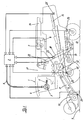
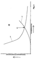
- FIG. 1 shows a side view of a combine harvester integrated computing device and Figure 2 two curves based on a soft optimization is carried out.
- a combine harvester 1 shows an example of a self-propelled agricultural vehicle, a schematic side view of a known combine harvester 1 is shown.
- the task of a combine harvester 1 is to harvest crops, such as grain, of a processing area 9 and of the straw and other admixtures to separate.
- crops such as grain
- For picking up the crop is in one on one Mower cutter 1, for example, attached cutting unit 10.
- Mower cutter 1 for example, attached cutting unit 10.
- the threshing device 12 In the threshing device 12 is struck by the and rubbing effect of the pre-accelerator drum and threshing drum, the crop released from the ears and separated from the straw. Then the crop arrives through the permeable concave on the preparation floor. That from the Threshing straw released, is braked by the turning drum and on transfer several shakers 14 arranged side by side over the working width. The vibratory movement of the shakers 14 and their step-shaped formation a promotion of the straw to the rear end of the combine 1 and one Separation of the crop still in the straw. This remaining amount is through the return floor and a swinging movement of the same also onto the preparation floor to hand over.
- This cleaning facility 13 is formed by a cleaning fan and the sieves. That of the Shakers 14 and the threshing device 12 separated crop is over a Pass the drop stage, ventilated by the cleaning fan, to the upper sieve.
- This and the bottom sieve underneath are usually lamellar sieves with each separately adjustable opening widths, the top sieve with a different opening width from the remaining opening width of the top sieve can be adjusted.
- the lower and the upper sieve are made by one of them Airflow generated by the cleaning fan.
- the swinging motion of the sieves as well as the air flow cause cleaning and promotion of the crop as well the additions to the rear end of the combine 1.
- Through the drop level be large and light admixtures of the airflow before they pass the top sieve reach, captured and deposited from combine 1.
- Smaller and heavier crop components reach the top sieve via the drop stage.
- the individual crop grains and others fall Components of the crop go through it and reach the bottom sieve.
- Short straw parts and non-threshed ears are placed over the front upper sieve area moves and falls, depending on the opening width and size, in the rear Area of the upper sieve through the upper sieve directly into the so-called tailings.
- the Bottom sieve usually has a finer sieve structure than the top sieve and is normally operated with a smaller opening width than the top sieve. Larger and light crop components, such as crop grains with husks, parts of ears or straw parts, provided that they have reached the lower sieve through the upper sieve, through the swinging movement and the air flow into the so-called return.
- the cleaned crop itself falls directly through the bottom sieve and becomes conveyed into the grain tank 17 by means of a feed screw and the grain elevator 18.
- the grain tank 17 is emptied by means of the grain tank emptying pipe 16 the crop is returned by means of a feed screw and the transfer elevator 19 conveyed back into the threshing device 12 and thus the threshing process again fed.
- the combine harvester 1 shown in FIG. 1 is equipped with a driver's cab 4.
- a display device 3 and a control device 5 connected to it are arranged in this.
- the display device 3 and the operating device 5 are connected to individual sensors and actuators which are arranged in different positions in the combine harvester 1 and which are distributed in the machine for remote-controlled setting and for recording settings and are known in principle to the person skilled in the art. This gives the operator of the combine 1 the opportunity to set and monitor the operation of the combine 1.
- the combine harvester 1 is equipped with a computing device 2 which is connected to at least the display device 3 via a bus connection 6.
- This computing device 2 contains a storage device, not shown, in which values entered via the operating device 5, such as operating values, working parameters or harvesting conditions, can also be stored, and furthermore general vehicle parameters can also be permanently stored.
- this computing device 2 can also be a computer, for example a mobile computer with its own display and storage device and with at least one interface to the bus system 6 of the combine harvester 1. Different combinations of the display device 3 with the computing device 2 and the operating device 5 and a computer are possible.
- a program is implemented on the computing device 2, which generates an economic operating value and / or an economic operating point and / or an economic working parameter for the combine harvester 1 and then displays it on the display device 3.
- a display can be omitted and the determined values / points / parameters can be used directly by another device on the combine harvester 1.
- various sensors which are known per se to the person skilled in the art, are connected to the computing device 2 directly or via the vehicle bus system 6, for detecting operating values, work parameters and work results. Some sensors are shown schematically in FIG.
- At least one cutting height sensor 21 is arranged on the cutting unit 10 and serves to determine the actual distance between the cutting unit 10 and the processing surface 9. The measured distance is fed to the computing device 2.
- a plurality of sensors for determining the setting and separation of crop can be arranged in the cleaning device 13.
- Such sensors 24 are known to the person skilled in the art and extend partially or completely over the working width of the devices 12, 13, 14 in the combine harvester 1.
- a loss sensor 25 can also be used at the end or directly behind the shakers 14.
- the computing device 2 provides the computing device 2 with a statement about the crop grains which are still lost at the end of the shaker 9 from the combine harvester 1.
- sensors known to the person skilled in the art can be arranged in the tailings, for example at the end of the lower sieve or at the point where the tailings are returned to the threshing process.
- further sensors can be attached to the return elevator 19 for detecting the return amount and, for example, also the grain breakage.
- the values recorded in each case are supplied to the computing device 2.
- the computing device 2 receives further information about the current operation of the combine harvester 1 from the sensors 22, 23 attached to the grain elevator 18.
- a yield sensor 22 determines the conveyed quantity of crop in the grain elevator 18.
- the crop moisture or the grain moisture is determined by the moisture sensor 23 and reported to the computing device 2.
- Further sensors for assessing the properties of the crop are known to the person skilled in the art and can be arranged in the combine harvester 1 and, if necessary, connected to the computing device 2 according to the invention.
- the drive motor 7 of the combine harvester 1 is equipped with control electronics 8 and provides the computing device 2, for example via a bus connection, the current fuel consumption of the combine harvester 1, the current output torque and thus the load on the combine harvester 1 and, for example, also maintenance signals.
- the respective actuators for setting the combine harvester 1 are sufficiently known to the person skilled in the art, so that the representation of the respective element can be omitted in FIG. 1.
- the computing device 2 generates an economic operating point and / or working parameters are calculated.
- This economic value is on a Display device 5, the operator of the combine 1 is displayed, the Value can be an absolute or relative value, which is then, for example, on a pointer instrument relative to an end stop or to a highlighted red / green area or is also displayed as an absolute value on the monitor.
- the economic operating value is for example a calculated economic area performance.
- This performance can according to the invention from the fuel consumption, the current driving speed and the cutting width of the cutting unit 10 can be calculated.
- the actual Driving speed and the current cutting width give the area performance in relation of working hours.
- the method according to the invention sets this area performance in relation to the current fuel consumption and shows the operator of the Combine 1, as an economic acreage, related to acreage on fuel consumption. How now a speed increase on the change affecting the economic acreage depends on the current one Relationship between the work input.
- the optimal working operation of the combine 1 in terms of economy can be used by the operator of the combine harvester 1, can be found out by simply varying the driving speed.
- the working operation can be optimized on the basis of, for example, a value or factor or else a characteristic curve.
- a value or factor or else a characteristic curve is known in principle and can be available as a general mathematical relationship in the form of a functional equation of the computing device 2.
- the relationship between the driving speed and the area performance is generally known and can be available to the computing device 2 as a factor, a characteristic curve or another functional equation for calculation.
- the general, known relationships to be calibrated on the basis of the current operating values, in that the operator of the combine harvester 1 transfers the current operating values to the computing device 2 during a calibration process by means of so-called learning.
- the computing device 2 then automatically determines factors or constants on the basis of the learned operating values and then calibrates the general functional equations to the current working mode.
- This calibration process can be extended further to a calibration run, in which relationships between operating values and working parameters and setting values are then learned using one or more constellations or one or more operating points and then stored in the storage device. For example, the crop throughput, crop loss and fuel consumption are learned at different driving speeds and then the necessary relationships are generated.
- the computing device 2 in conjunction with the known relationships, can determine an optimized economic area performance and show it to the operator of the combine harvester 1.
- a storage device on the combine harvester 1 by means of devices known to the person skilled in the art, such as via the operating device 5, via a known memory card or via known data transmission paths, such as radio connections or an Internet connection, the possible proceeds from the harvesting of the crop, the machine costs and / or or time-related, maintenance costs, labor costs as well as operating costs and / or economic comparative values, such as the costs of an external work, are stored.
- economic operating data such as the current fixed and variable costs, can then be determined from this. For an economic view of the harvest costs, these can be related to the current area output and / or the crop throughput and displayed to the operator of the combine harvester 1.
- FIG. 2 shows a first curve K1, which indicates a harvest cost value in connection with the crop throughput.
- Another curve E1 shows the relationship between a loss cost value and the crop throughput.
- the intersection S12 of the two curves K1 and E1 represents an optimum for the current operation of the combine harvester 1. At this point S1, at a certain crop throughput, an optimum is achieved between the loss cost value increasing with increasing crop throughput and the falling harvest cost value.
- the crop throughput is determined by the area output of the combine harvester 1 and the yield on the processing area 9 and also depends on the combine harvester setting.
- the diagram 26 shown it relates to the grain yield per harvest hour determined by a yield sensor 22.
- the crop loss is also dependent on the crop throughput. From this, the loss cost value in connection with the proceeds of the crop is determined according to the invention.
- the relationship between the crop throughput and the crop loss can be calculated from known characteristics stored in the storage device, depending on the crop type, crop type and crop moisture, and / or derived from the signals from sensors 24, 25 for crop loss in combine harvester 1.
- the harvest cost value is an example of costs that arise from the operation and are incurred in relation to the harvest time.
- the focus here is on machine, maintenance and driver costs.
- the costs incurred by the work during operation, such as, for example, the loss of crops or the consumption of operating resources, are indicated by the loss cost value.
- the optimization for calculating the economic operating point or economic working parameter according to the invention shows an optimum between the yield of the combine harvester and the revenue-reducing costs of the current harvesting operation.
- the current operating values and work results constantly determine the optimal operating conditions with regard to the economy of the work, for example, the switching on of the straw chopper is recognized based on a higher downforce on the engine or a higher fuel consumption and flows directly into the economic operating value and, if necessary, into the optimization process on.
- the stubble height can also be evaluated according to the invention by the signal from the cutting height sensor 21 and, for example, storage cereals can be recognized on the basis of this height and additional harvesting costs can then be taken into account in the harvesting cost value.
- the values of the determined crop moisture determine the costs of harvesting and subsequent crops and, according to the invention, can be economically evaluated directly in the harvesting operation.
- the exemplary embodiments mentioned can also be transferred in particular to self-propelled forage harvesters and used there according to the invention.
- the harvest costs in connection with the crop throughput are displayed as an economic operating value.
- the crop throughput can be displayed in connection with the area output and / or the fuel consumption according to the invention.
- the optimizations mentioned, based on the area performance in relation to the crop throughput and in relation to the variable harvest costs, can also be used here and, according to the invention, serve the operator of the forage harvester to optimize the working operation.
- the invention is not limited to the exemplary embodiments specified and illustrated facilities, but covers all types of agricultural Vehicles and work with this, especially those that have a quantifiable number Work performance in connection with a known and determinable cost situation performance in connection with a known and determinable cost situation provide.
- tractors and / or carrier vehicles are also included mounted and / or attached implements, such as mowers or tillage implements called.
Abstract
Description
Diese Erfindung betrifft ein Verfahren und eine Vorrichtung zur Optimierung des Betriebs eines landwirtschaftlichen Fahrzeugs, wie beispielsweise Mähdrescher oder Feldhäcksler oder Traktor, mit wenigstens einer Einrichtungen zur Erfassung von Betriebswerten und/ oder Arbeitsergebnissen und wenigstens einer Rechen-, Speicherund Anzeigeeinrichtung.This invention relates to a method and an apparatus for optimizing operation an agricultural vehicle, such as combine harvesters or Forage harvester or tractor, with at least one device for recording operating values and / or work results and at least one computing, storage and Display means.
An landwirtschaftlichen Fahrzeugen, insbesondere selbstfahrenden landwirtschaftlichen
Fahrzeugen ist es bekannt, durch Einrichtungen, wie Taster, Dreh- und Stellelemente
sowie Sensoren, Betriebswerte, Erntebedingungen und/oder Einstellwerte vorzugeben
oder zu erfassen. Mittels Anzeige-, Speicher- und Recheneinrichtung, können
diese Werte auch in Verbindung mit weiteren abgespeicherten Fahrzeugparametern
oder Einstellungen, in Informationen über den momentanen Arbeitsbetrieb für den Maschinenbediener
aufbereitet und angezeigt werden.
An Mähdreschern sind Einrichtungen bekannt, die eine Auswahl von Einstellparametern
für den Arbeitsbetrieb in Abhängigkeit einer Erntegutart ermöglichen. Hierzu wählt
der Bediener eines Mähdreschers über ein Bedienterminal eine Erntegutart aus, ruft
für diese eine oder mehrere Einstellparameter für die einzelnen Arbeitsaggregate des
Mähdreschers, wie Dreschspaltweite, Dreschtrommeldrehzahl oder Sieböffnungsweite,
aus einer Speichereinrichtung ab und veranlasst dann die direkte automatische Einstellung
dieser Einstellwerte an den entsprechenden Arbeitsaggregaten. Durch entsprechende
Anzeigen auf einem Bedienterminal, wird der Bediener des Mähdreschers
laufend über die Arbeitsergebnisse, wie die Fahrgeschwindigkeit, den Ernteertrag, die
Ernteverluste und weitere Parameter des Ernteprozesses und des Mähdreschers informiert.
Die in der Speichereinrichtung hinterlegten Einstellparameter stellen Grundeinstellungen
für eine Erntegutart dar und liefern in der Regel ein erstes, brauchbares
Arbeitsergebnis. Da sich jedoch die Erntebedingungen von Jahr zu Jahr oder während
des Erntebetriebs oftmals ändern, wie zum Beispiel anhand der Erntegutsorte, Erntegutfeuchte
oder dem Reifegrad, ist in vielen Fällen eine nachhaltige Verbesserungen
der Einstellung notwendig. Diese wird dann je nach Qualifizierung des Bedieners von
diesem empirisch vorgenommen.
Aus dem Stand der Technik sind verschiedene Einrichtungen auf einem Mähdrescher
bekannt geworden, die automatisch eine Einstellung eines Arbeitsaggregates oder der
Fahrgeschwindigkeit in Abhängigkeit wenigstens eines Arbeitsergebnisses erzeugen
oder sogar regeln. Beispielsweise sei hier auf die DE 197 05 841 A1 verwiesen.
Diese bekannten Einrichtungen an Mähdreschern erbringen lediglich die Möglichkeit,
möglichst schnell eine brauchbare Maschineneinstellung zu finden oder diese durch
eine Regelung selbsttätig führen zu lassen. Ernteziele müssen daher von dem Bediener
des Mähdreschers selbst beachtet und bei der entsprechenden Auswahl und Einstellung
des Mähdreschers berücksichtigt werden. Dieser Mangel wird durch eine Einrichtung,
die in der DE 198 00 238 C1 offenbart ist, behoben. Dort werden Einstellparametern
für eine Mähdreschereinstellung unter Berücksichtigung von verschiedenen
Konstellationen von äußeren Erntebedingungen und einer Zielvorgabe in einer Speichereinrichtung
auf einem Mähdrescher hinterlegt und zur Einstellung des Mähdreschers
im Erntebetrieb auswählbar bereit gehalten. Nachteilig an dieser Lösung ist
jedoch die von dem subjektiven empfinden des Bedieners abhängige Auswahl der äußeren
Erntebedingungen sowie der Zielvorgabe und die notwendige vorherige Ermittlung
und Hinterlegung von Einstellparametern, zu sämtlichen im Betrieb des Mähdreschers
vorkommenden Konstellationen von Erntebedingungen und deren Auswertung
im Hinblick auf die verschiedenen Zielvorgaben. Eine Aussage inwieweit der Mähdrescher
dann die Zielvorgabe erfüllt und diese Zielvorgabe ferner in den gesamten Erntebetrieb
passt, kann nicht gemacht werden.
In der DD 289 686 A5 wird ein Verfahren zum Ausgleich von Meßdifferenzen an Bordsystemen
an einem Mähdrescher vorgeschlagen. Durch diesen Ausgleich können Unregelmäßigkeiten
der Arbeitsergebnisse des Mähdreschers zwischen der Dichte, der
Feucht und der Verluste ausgeglichen und ein Grundwert für die Trennaktivität des
Mähdreschers von einem Bordcomputer bestimmt werden. Das Verhältnis der konkreten
Verlustwerte zu diesem Trennaktivitätswert, gibt einen ökonomischen Leistungswert
an, durch welchen die Gesamterntesituation des Mähdreschers in Verbindung
eines zuvor bestimmten optimalen Leistungswertes beurteilt werden kann. Der optimale
Leistungswert wird von einem Personalcomputer anhand von Erntezielen und Erntewerten
bestimmt und auf den Bordcomputer des Mähdreschers übertragen. Durch
diese vorgeschlagene Lösung, wird dem Bediener des Mähdreschers eine Maschinenanzeige
zu Verfügung gestellt, anhand welcher er seine momentane Maschinenleistung
im Verhältnis zu der vorgeschlagenen Ernteleistung, im Hinblick auf die Gesamternteeinbringung
beurteilen kann. Diese Lösung bedingt eine Vielzahl von Sensoren
sowie unterschiedliche Sensoren entlang des gesamten Durchlaufweges von Erntegut
durch den Mähdrescher und ist daher aufwendig und mit hohen Kosten verbunden.
Ferner erbringt dieser vorgeschlagene Ausgleich von Messwertdifferenzen die
Möglichkeit, einen Vergleich des aktuellen Erntebetriebs in Verbindung einer fixen
Vorgabe durchführen zu können. Diese Vorgabe kann zwar unter ökonomischen Betrachtungen
lokal auf einem Computer generiert werden, ist aber als solche für den
Bediener nicht nachvollziehbar. Der Vergleichswert erscheint dem Bediener lediglich
als ein Sollwert für den Betrieb des Mähdreschers und beinhaltet speziell ein Verhältnis
der Durchsatzleistung zu den Verlusten. Für den Bediener stellt diese Vorgabe keine
nachvollziehbare ökonomische Betrachtungsweise des momentanen Erntebetriebs
dar.On agricultural vehicles, in particular self-propelled agricultural vehicles, it is known to specify or record devices, operating values, harvesting conditions and / or setting values by means of devices such as buttons, rotary and actuating elements as well as sensors. By means of a display, storage and computing device, these values can also be prepared and displayed for the machine operator in connection with further stored vehicle parameters or settings, in information about the current working mode.
Devices are known on combine harvesters that enable a selection of setting parameters for the work operation depending on a crop type. For this purpose, the operator of a combine harvester selects a type of crop via an operating terminal, calls up one or more setting parameters for the individual working aggregates of the combine harvester, such as threshing gap width, threshing drum speed or sieve opening width, from a storage device and then initiates the direct automatic adjustment of these setting values to the corresponding one working units. The operator of the combine is continuously informed of the work results, such as the driving speed, the crop yield, the crop losses and other parameters of the harvesting process and the combine, by means of appropriate displays on a control terminal. The setting parameters stored in the storage device represent basic settings for a crop type and generally provide a first, usable work result. However, since the harvesting conditions often change from year to year or during harvesting, for example based on the type of crop, crop moisture or the degree of ripeness, a sustainable improvement in the setting is necessary in many cases. Depending on the qualification of the operator, this is then carried out empirically by the operator.
Various devices on a combine harvester are known from the prior art, which automatically generate or even regulate an adjustment of a work unit or the driving speed depending on at least one work result. For example, reference is made to DE 197 05 841 A1. These known devices on combine harvesters only provide the option of finding a usable machine setting as quickly as possible or of having it automatically managed by a control system. Harvest targets must therefore be observed by the operator of the combine himself and taken into account when selecting and adjusting the combine. This deficiency is remedied by a device which is disclosed in DE 198 00 238 C1. There, setting parameters for a combine harvester setting, taking into account different constellations of external harvesting conditions and a target, are stored in a storage device on a combine harvester and are selectively kept ready for setting the combine harvester in harvesting operation. A disadvantage of this solution, however, is the selection of the external harvesting conditions and the target, which is dependent on the subjective perception of the operator, and the necessary prior determination and storage of setting parameters, for all constellations of harvesting conditions that occur in the operation of the combine and their evaluation with regard to the various targets , No statement can be made as to the extent to which the combine then meets the target and that this target also fits the entire harvesting operation.
DD 289 686 A5 proposes a method for compensating measurement differences in on-board systems on a combine harvester. This compensation can compensate for irregularities in the work results of the combine between the density, the moisture and the losses and a basic value for the separating activity of the combine can be determined by an on-board computer. The ratio of the specific loss values to this separation activity value specifies an economic performance value by means of which the overall harvest situation of the combine harvester can be assessed in connection with a previously determined optimal performance value. The optimal performance value is determined by a personal computer on the basis of harvest targets and harvest values and is transferred to the on-board computer of the combine harvester. With this proposed solution, the operator of the combine harvester is provided with a machine display by means of which he can assess his current machine output in relation to the proposed harvesting output with regard to the total harvesting. This solution requires a large number of sensors and different sensors along the entire throughput path of the crop through the combine harvester and is therefore complex and associated with high costs. Furthermore, this proposed compensation of measured value differences provides the possibility of being able to compare the current harvesting operation in connection with a fixed specification. This specification can be generated locally on a computer from an economic point of view, but as such is not comprehensible for the operator. The comparison value only appears to the operator as a setpoint for the operation of the combine and specifically includes a ratio of the throughput to the losses. For the operator, this specification does not represent a comprehensible economic view of the current harvest operation.
Es ist daher Aufgabe der Erfindung, auf einem landwirtschaftlichen Fahrzeug eine Möglichkeit zu schaffen, die dem Bediener des Fahrzeugs während dem Arbeitsbetrieb zumindest eine Information darüber gibt, inwieweit das Fahrzeug ökonomisch arbeitet.It is therefore an object of the invention, a on an agricultural vehicle Possibility to create the operator of the vehicle while working gives at least information about the extent to which the vehicle works economically.
Die Aufgabe wird durch ein Verfahren auf einem landwirtschaftlichen Fahrzeug gelöst,
welches dadurch gekennzeichnet ist, dass auf dem Fahrzeug unter Berücksichtigung
wenigstens eines ermittelten und/oder in einer Speichereinrichtung hinterlegten Parameters,
zumindest ein ökonomischer Betriebswert und/oder ökonomischer Arbeitsparameter
für das Fahrzeug berechnet und dem Bediener des Fahrzeugs angezeigt
und/oder von einer weiteren Einrichtung des Fahrzeugs berücksichtigt wird.
Dieses Verfahren generiert aus den im Betrieb des Fahrzeugs herrschenden Parametern,
wenigstens einen Betriebswert auf einer Anzeige, der ständig von dem Bediener
des Fahrzeugs eingesehen werden kann und vorteilhaft somit jederzeit Aufschluss
über die aktuelle ökonomische Betriebsweise seines Fahrzeugs gibt. Der Betriebswert
wird vorteilhaft in der Recheneinrichtung auf dem Fahrzeug selbst generiert und ist
daher nicht von externen Einrichtungen und externen Datenübertagungsstrecken abhängig.
Das erfindungsgemäße Verfahren kann ferner vorteilhaft einen ökonomischen
Arbeitsparameter aus wenigstens einem im Betrieb des Fahrzeugs herrschenden Parameter
generieren. Hierdurch wird schon bei der Generierung von Arbeitsparametern,
aus dem aktuellen Betrieb heraus, für beispielsweise die Einstellung des Fahrzeugs,
eine ökonomische Betrachtung der aktuellen Betriebsweise des Fahrzeugs, mit von
der Recheneinrichtung berücksichtigt. Die von dem erfindungsgemäßen Verfahren
generierten Betriebswerte und/oder Arbeitsparameter lassen sich vorteilhaft auch in
einer weiteren Einrichtung des Fahrzeugs weiter verwenden, indem diese Einrichtungen
vorteilhaft die generierte Größe oder die generierten Größen berücksichtigt. Diese
Betriebswerte oder Arbeitsparameter können in weiteren Einrichtungen, vorteilhaft als
Sollgrößen für eine Steuerung oder Regelung von weiteren Betriebswerten oder Arbeitsparametern
des Fahrzeugs verwendet werden.The object is achieved by a method on an agricultural vehicle, which is characterized in that at least one economic operating value and / or economic working parameter for the vehicle is calculated on the vehicle, taking into account at least one parameter determined and / or stored in a storage device, and the Operator of the vehicle is displayed and / or is taken into account by another device of the vehicle.
From the parameters prevailing in the operation of the vehicle, this method generates at least one operating value on a display that can be viewed continuously by the operator of the vehicle and thus advantageously provides information about the current economic mode of operation of his vehicle at any time. The operating value is advantageously generated in the computing device on the vehicle itself and is therefore not dependent on external devices and external data transmission routes. The method according to the invention can also advantageously generate an economic working parameter from at least one parameter prevailing in the operation of the vehicle. As a result, an economic consideration of the current mode of operation of the vehicle is already taken into account by the computing device when generating working parameters from current operation, for example for setting the vehicle. The operating values and / or working parameters generated by the method according to the invention can advantageously also be used in a further device of the vehicle, in that these devices advantageously take into account the generated size or the generated sizes. These operating values or working parameters can be used in further devices, advantageously as target values for controlling or regulating further operating values or working parameters of the vehicle.
In einer weiteren Ausgestaltung der Erfindung wird der ökonomische Betriebswert und/oder ökonomische Arbeitsparameter zunächst optimiert und dann als ein ökonomischer Betriebspunkt und/oder Arbeitsparameter angezeigt und/oder von einer weiteren Einrichtung des Fahrzeugs berücksichtigt. Es entsteht nun vorteilhaft für den Bediener des Fahrzeugs die Möglichkeit, seinen Arbeitsbetrieb zu optimieren. Der erfindungsgemäß angezeigte ökonomische Betriebswert steht direkt mit den aktuellen Betriebsbedingungen des Fahrzeugs in Verbindung, wobei der ökonomische Betriebspunkt zunächst optimiert und dann erst dem Bediener angezeigt wird. Vorteilhaft besteht nun für den Fahrzeugbediener die Möglichkeit einen Vergleich zwischen dem Betriebswert und dem Betriebspunkt durchführen und gegebenenfalls seine Betriebsbedingungen so ändern zu können, dass der ökonomische Betriebspunkt durch abgeleitete veränderte Betriebsbedingungen erreicht werden kann. Dieser optimierte Wert kann vorteilhaft als Sollwert zur Optimierung des Betriebs des Fahrzeugs auf einer Anzeigeeinrichtung dem Bediener angezeigt und/oder direkt in einer weiteren Einrichtung auf dem Fahrzeug, zur Regelung und/oder Steuerung des zu Grunde liegenden Betriebswertes und/oder Arbeitspunktes herangezogen werden. In a further embodiment of the invention, the economic operating value and / or economic work parameters first optimized and then as an economic one Operating point and / or working parameters displayed and / or from another Set up the vehicle. It is now advantageous for the operator the vehicle the opportunity to optimize its work. The invention The economic operating value displayed is directly related to the current operating conditions of the vehicle in connection, the economic operating point first optimized and only then displayed to the operator. It is advantageous now the possibility for the vehicle operator to compare the Carry out the operating value and the operating point and, if necessary, its operating conditions to be able to change so that the economic operating point is derived from changed operating conditions can be achieved. This optimized value can advantageously be used as a setpoint for optimizing the operation of the vehicle on a Display device displayed to the operator and / or directly in another device on the vehicle, to regulate and / or control the underlying Operating value and / or operating point can be used.
In einer Ausgestaltung der Erfindung wird ein ökonomischer Betriebswert und/oder ökonomischer Betriebspunkt und/oder ökonomischer Arbeitsparameter von einer auf einer als Computer ausgebildeten Recheneinrichtung laufenden Optimierungssoftware generiert. Eine Optimierungssoftware auf einem Computer erbringt für den Bediener des Fahrzeugs vorteilhaft eine bekannte Software- Bedienungsmöglichkeit sowie die Verwendung einer fahrzeugunabhängigen Optimierungssoftware, mit bekannter Leistungsfähigkeit. Femer werden die auf den landwirtschaftlichen Fahrzeugen eingesetzten Recheneinrichtungen, die hierfür mit speziell geeigneten Prozessoren ausgestattet zur Steuerung und Regelung der Arbeitsabläufe dienen, nicht zusätzlich mit Programmen und Programmlaufzeiten belastet.In one embodiment of the invention, an economic operating value and / or economic operating point and / or economic working parameters from one an optimization software running as a computer generated. Optimization software on a computer provides for the operator the vehicle advantageously a known software operation option and the Use of vehicle-independent optimization software with known performance. They are also used on agricultural vehicles Computing devices equipped for this with specially suitable processors serve to control and regulate the work processes, not additionally with programs and program run times.
In einer Weiterbildung der Erfindung, wird bei der Berechung zusätzlich wenigstens ein Arbeitsergebnis berücksichtigt. Durch die Einbeziehung eines Arbeitsergebnisses, lässt sich die Optimierung des wenigstens einen ökonomischen Betriebswertes und/oder einen ökonomischen Betriebspunktes und/oder ökonomischen Arbeitsparameters weiter verbessern. So stehen die im Arbeitsbetrieb herrschenden Betriebswerte und/oder Arbeitsparameter und/oder Erntebedingungen des Fahrzeugs auch im Zusammenhang mit den Arbeitsergebnissen und werden von diesen beeinflusst. Theoretische, von der Optimierungssoftware abgeleitetet Arbeitsergebnisse können hierdurch auf die tatsächlichen Werte abgeglichen werden und vorteilhaft korrigiert in eine Optimierung einfliesen. Beispielsweise kann hiermit die in der Recheneinrichtung aktivierte Durchsatz-/ Verlustkennlinien ständig an den aktuellen Durchsatz/Verlustwert angepasst und/oder eine den aktuellen Werten entsprechenden Kennlinie ausgewählt werden.In a development of the invention, at least one is additionally used in the calculation Work result taken into account. By including a work result, can optimize the at least one economic operating value and / or an economical operating point and / or economical work parameter continue to improve. This is how the operating values prevail in the work operation and / or working parameters and / or harvesting conditions of the vehicle also in context with the work results and are influenced by them. theoretical, This enables work results derived from the optimization software be adjusted to the actual values and advantageously corrected in an optimization tiling. For example, the one activated in the computing device can hereby Throughput / loss characteristics are continuously adapted to the current throughput / loss value and / or a characteristic curve corresponding to the current values can be selected.
Erfindungsgemäß ist der Parameter ein Betriebswert, welcher fixe und/oder variable Fahrzeugkosten und/oder Arbeitskraftkosten und/oder den Ernteguterlös und/oder Ernte- oder Erntegutnachbearbeitungskosten und/oder wenigstens eine Betriebskennlinie und/oder Ernteanforderungen beinhaltet. Hierdurch wird eine Bewertung und Optimierung des Betriebes des Fahrzeugs anhand des gesamten Kostenumfeldes des Fahrzeugs, auch in Bezug auf das Gesamtergebnis des Agrarbetriebes möglich. Während des Betriebes des Fahrzeugs, werden vorteilhaft jederzeit die im Betrieb herrschenden Bedingungen und/oder Arbeitsergebnisse anhand der Kosten und/oder des Erlöses und/oder von Betriebskennlinien oder/und den Ernteanforderungen bewertet und ermöglicht somit eine direkte Ermittlung von Betriebswerten und/oder Betriebspunkten und/oder Arbeitsparametern, anhand ökonomischer Betrachtungen und Gesichtspunkten.According to the invention, the parameter is an operating value, which is fixed and / or variable Vehicle costs and / or labor costs and / or crop proceeds and / or harvest or crop post-processing costs and / or at least one operating characteristic and / or harvest requirements. This is an evaluation and optimization the operation of the vehicle based on the overall cost environment of the vehicle, also possible in relation to the overall result of the agricultural business. While operation of the vehicle, those prevailing in operation are advantageous at all times Conditions and / or work results based on costs and / or proceeds and / or evaluated and enabled by operating characteristics or / and the harvesting requirements thus a direct determination of operating values and / or operating points and / or work parameters, based on economic considerations and points of view.
In einer weiteren Ausgestaltung der Erfindung, ist der Parameter ein Arbeitsparameter, welcher wenigstens einen Einstellwert eines Fahrzeugs und/oder die Arbeitsbreite und/oder die Fahrgeschwindigkeit und/oder wenigstens ein Verbrauchs- und/oder Verschleiß- und/oder Leistungs- und/oder Drehmoment- und/oder Drehzahlwert wenigstens eines Fahrzeugsaggregates beinhaltet. Vorteilhaft werden hierdurch, die von den Bedienern des Fahrzeugs durchgeführten, manuellen oder auch durch Steuer- und Regeleinrichtungen vorgegeben Einstellungen an dem Fahrzeug und die sich an den Arbeitsaggregaten einstellenden Betriebswerte erfindungsgemäß berücksichtigt und verwertet. Auch die Beachtung von Verschleißwerten, beispielsweise an Reifen, Messern, Ketten oder Arbeitswerkzeugen allgemein, lassen vorteilhaft einen Bewertung in einer ökonomischen Betrachtung und Bewertung sowie Rückschlüsse auf die Arbeitsweise des Fahrzeugs zu und können dann erfindungsgemäß berücksichtigt werden.In a further embodiment of the invention, the parameter is a working parameter, which is at least one setting value of a vehicle and / or the working width and / or the driving speed and / or at least one consumption and / or wear and / or power and / or torque and / or speed value at least of a vehicle unit includes. This will be advantageous by the Operators of the vehicle performed, manual or also by control and Control devices predefined settings on the vehicle and those to the Operating values setting work units are taken into account according to the invention and recycled. Consideration of wear values, for example on tires, knives, Chains or work tools in general, advantageously leave an assessment in an economic view and evaluation as well as conclusions about the way of working of the vehicle and can then be taken into account according to the invention.
In einer weiteren Ausgestaltung der Erfindung, ist der Parameter eine Erntebedingung, welche die Erntegutart und/oder die Erntgutfeuchte und/oder die Strohfeuchte und/oder die Umgebungsluftfeuchte und/oder die Tageszeit und/oder der Reifegrad und/oder die geografische Lage beinhaltet. Die Bedingungen können vorteilhaft direkt aus den elektronischen Bordsystemen an den Fahrzeugen entnommen oder auch manuell eingeben werden. Es ergibt sich vorteilhaft eine genauere erfindungsgemäße ökonomische Ermittlung von Punkten und/oder Parametern, insbesondere bei der Ermittlung der aktuellen Betriebskosten des Fahrzeuges.In a further embodiment of the invention, the parameter is a harvesting condition, which the crop type and / or the crop moisture and / or the straw moisture and / or the ambient air humidity and / or the time of day and / or the degree of maturity and / or the geographic location. The conditions can advantageously be direct removed from the electronic on-board systems on the vehicles or manually will be entered. A more precise result according to the invention advantageously results economic determination of points and / or parameters, especially during the determination the current operating costs of the vehicle.
In einer weiteren Ausgestaltung der Erfindung, ist das Arbeitsergebnis, der Gutdurchsatz und/oder der Erntegutdurchsatz und/oder die Erntegutabscheidung im Mähdrescher und/oder der Emtegutverlust und/oder die Erntegutstruktur und/oder die Erntegutsauberkeit und/oder der Ertrag. Hierdurch lassen sich vorteilhaft Rückschlüsse auf die momentane Arbeitserledigung des Fahrzeugs und die anfallenden Kosten schließen und insbesondere eine Abschätzung und Ermittlung von Fahrzeug- und/oder Folgekosten durchführen. Weiterhin lässt sich aus wenigstens einem Arbeitsergebnis, der zu erwartende Erlös aus der anschließenden Vermarktung des Erntegutes oder die zu erwartenden Einkünfte durch die Arbeitserledigung ermitteln. Eine weitere Verbesserung der ökonomischen Betrachtung des Fahrzeugeinsatzes ist hierdurch vorteilhaft schon auf dem Fahrzeug möglich und kann ferner dann schon während der Erledigung der Arbeit berücksichtigt und in einer entsprechende Auswertung und/oder Beeinflussung des Arbeitsbetriebes berücksichtigt werden.In a further embodiment of the invention, the work result is the throughput and / or the crop throughput and / or the crop separation in the combine and / or crop loss and / or crop structure and / or crop cleanliness and / or the yield. This advantageously allows conclusions to be drawn close the current job completion of the vehicle and the costs incurred and in particular an estimation and determination of vehicle and / or follow-up costs carry out. Furthermore, from at least one work result, the expected proceeds from the subsequent marketing of the harvested crop or the determine expected income from the job completion. Another improvement the economic consideration of vehicle use is advantageous already possible on the vehicle and can then already during the completion the work is taken into account and in a corresponding evaluation and / or influencing of the working company are taken into account.
In einer besonderen Ausgestaltung der Erfindung, wird als der ökonomische Betriebswert, ein ökonomischer Erntegutdurchsatz und/oder wenigstens ein Erntegutverlust und/oder eine ökonomische Flächenleistung berechnet. Vorteilhaft stellen die genannten Betriebswerte, für den Bediener der Erntemaschine, bekannte Kenngrößen für den Betrieb des Fahrzeugs dar, sodass er es erfahrungsgemäß leicht versteht, anhand des angezeigten ökonomischen Betriebswerte, das Fahrzeug zur Erzielung einer Verbesserung des Arbeitsbetriebes anhand der ökonomischen Anzeige manuell einstellen zu können. Vorteilhaft wird der ermittelte Betriebswert optimiert und als ökonomischer Betriebspunkt angezeigt, wodurch der Bediener des Fahrzeugs eine Hilfestellung zur Findung des besten Betriebswertes erhält. Der Bediener braucht dann nur den aktuellen angezeigten ökonomischen Betriebswert mit dem aktuellen ökonomischen Betriebspunkt zu vergleichen und erhält aus der Differenz, eine Information darüber, welcher Betriebswert zur Erzielung des optimalen ökonomischen Betriebswertes gewählt werden sollte. Auch sind auf den Fahrzeugen, Sensor- und Anzeigeeinrichtungen für diese Größen bekannt und vorhanden, sodass vorteilhaft ein Einsatz zusätzlicher Sensoren und Anzeigemitteln nicht notwendig wird.In a special embodiment of the invention, the economic operating value, an economic crop throughput and / or at least a crop loss and / or an economic area performance is calculated. Advantageously represent the above Operating values, for the operator of the harvester, known parameters for the Operation of the vehicle, so that, based on experience, he understands it easily based on the displayed economic operating values, the vehicle to achieve an improvement the work operation manually based on the economic display can. The determined operating value is advantageously optimized and more economical Operating point displayed, which helps the operator of the vehicle to Finding the best operating value. The operator then only needs the current one displayed economic operating value with the current economic operating point to compare and get from the difference, information about which Operating value selected to achieve the optimal economic operating value should be. Also on the vehicles are sensor and display devices for these sizes are known and available, so it is advantageous to use additional sensors and display means is not necessary.
In einer weiteren Ausgestaltung der Erfindung, wird aus dem Erntegutdurchsatz und dem Erntegutverlust in Verbindung mit den Erntekosten und dem Ernteguterlös sowie wenigstens einer Betriebskennlinie, ein ökonomischer Erntegutverlustpunkt berechnet. Vorteilhaft lässt sich hierdurch aus der momentanen Erntekosten- und Erlössituation ein ökonomischer optimaler Erntegutverlustpunkt bestimmen. Dieser zeigt dem Bediener des Mähdreschers einen ökonomischen Betriebspunkt für genau diese Erntesituation an. Änderungen in der Markt- und/oder Kostenssituation werden hierdurch schon während des Betriebs des Mähdreschers berücksichtigt.In a further embodiment of the invention, the crop throughput and the crop loss in connection with the harvest costs and the crop proceeds as well at least one operating characteristic, an economic crop loss point is calculated. This can be advantageous from the current harvest cost and revenue situation determine an economical optimal crop loss point. This shows the operator of the combine harvester is an economical operating point for precisely this harvesting situation on. This already changes in the market and / or cost situation taken into account during the operation of the combine.
Eine weitere Lösung der erfindungsgemäßen Aufgabe, wird durch eine Optimierungseinrichtung auf einem landwirtschaftlichen Fahrzeug gegeben, die dadurch gekennzeichnet ist, dass die Recheneinrichtung anhand von wenigstens einem in der Speichereinrichtung hinterlegten Wert und aus wenigstens einem Ergebnis des momentanen Arbeits- und/ oder Erntebetriebs wenigstens einen ökonomischen Betriebswert und/oder einen ökonomischen Betriebspunkt und/oder einen ökonomischen Arbeitsparameter für das Fahrzeug ermittelt und auf einer Anzeigeeinrichtung darstellt und/oder von einer weiteren Einrichtung auf dem Fahrzeug berücksichtigt. Die Integration einer Optimierungseinrichtung direkt auf einem Fahrzeug erbringt den Vorteil, dass direkt auf dem Fahrzeug in Verbindung mit dem laufenden Betrieb, eine Optimierung des Betriebs durchgeführt werden kann. Die Optimierung kann dabei direkt anhand von den im Betrieb vorkommenden Einstellungen und Werten durchgeführt werden. Vorteilhaft entfällt ein Datenaustausch zu weiteren Einrichtungen außerhalb des Fahrzeugs. Des weiteren wird der Bediener des Fahrzeugs selbst mit der Optimierungseinrichtung in Verbindung gebracht, wodurch der Bedienern vorteilhaft, beispielsweise durch die Eingabe von Betriebswerte oder Erntebedingungen sowie durch die Anzeige der ermittelten Betriebspunkte oder Arbeitsparameter, auf die ökonomisch bedeutsamen Größen hingewiesen und damit vertraut gemacht wird. Er wird direkt in den Optimierungsprozess mit einbezogen und kann selbst durch Versuche, Einstellungen an dem Fahrzeug durchführen, um die Einflüsse auf den ökonomischen Betriebswert und Arbeitsparameter empirisch zu ermitteln und erhält hierdurch vorteilhaft eine Gefühl für ökonomisch wichtige Einflüsse im Arbeitsbetrieb.Another solution to the problem according to the invention is provided by an optimization device given on an agricultural vehicle, which is characterized is that the computing device is based on at least one in the storage device stored value and from at least one result of the current Labor and / or harvest operation at least one economic operating value and / or an economic operating point and / or an economic working parameter determined for the vehicle and displayed on a display device and / or taken into account by another device on the vehicle. The integration of a Optimization device directly on a vehicle provides the advantage of being direct on the vehicle in conjunction with ongoing operations, an optimization of the Operation can be carried out. The optimization can be done directly using the settings and values that occur during operation. Advantageous there is no data exchange with other facilities outside the vehicle. Furthermore, the operator of the vehicle himself with the optimization device associated, making the operator advantageous, for example by entering operating values or harvesting conditions and by displaying the determined operating points or working parameters to the economically significant ones Sizes pointed out and familiarized with. He will go straight into the optimization process involved and can even by trying to adjust settings perform the vehicle to determine the influences on the economic operating value and To empirically determine working parameters and thereby advantageously get a feel for economically important influences in work.
In einer weiteren Ausgestaltung der Erfindung, wird die Recheneinrichtung von einem Computer gebildet, der mit dem Fahrzeug über wenigstens eine Schnittstelle Daten austauscht. Die in den Fahrzeugen eingesetzten Recheneinrichtungen sind in der Regel für die Steuerung und Regelung von Prozessen in dem Fahrzeug ausgelegt und besitzen hierfür geeignete Prozessoren sowie benötigen hierfür spezielle Programmierungen. Durch den Einsatz eines Computers, der mit Standartkomponenten ausgestattet ist, wird eine kostengünstige Lösung mit einer weit höheren Leistungsfähigkeit gegenüber den fahrzeugeigenen Recheneinrichtungen geschaffen. Die Integration eines Computers auf dem Fahrzeug erbringt ferner den Vorteil, dass vorhandene leistungsfähige Optimierungsprogramme direkt auf dem Fahrzeug eingesetzt werden können und der Computer dann über lediglich wenigstens eine vorhandene bekannte Schnittstelle mit dem Fahrzeug Daten austauschen kann. In a further embodiment of the invention, the computing device is operated by one Computer formed that data with the vehicle via at least one interface exchanges. The computing devices used in the vehicles are usually designed for the control and regulation of processes in the vehicle and have suitable processors for this and require special programming for this. By using a computer equipped with standard components is compared to an inexpensive solution with a far higher performance the vehicle's own computing facilities. The integration of one Computers on the vehicle also has the advantage of being powerful Optimization programs can be used directly on the vehicle and the computer then via only at least one existing known interface can exchange data with the vehicle.
Ein ökonomischer Wert zeigt generell die Beziehung zwischen den Aufwendungen und der daraus resultierenden Leistung an. In der vorliegenden Erfindung werden Fahrzeuge landwirtschaftlich eingesetzt und erbringen dabei eine für den Agrarbetrieb wertvolle Arbeitsleistung. Im Vorfeld ist es, beispielsweise von einem Betriebsleiter, immer zu entscheiden, ob eine ausstehenden Arbeit intern oder extern erledigt werden sollte. Diese Entscheidung wird in der Regel anhand einer Dringlichkeit und den zur Verfügung stehenden Möglichkeiten und Mitteln sowie anhand einer Kosten/Nutzen-Betrachtung entschieden. Für den danach erfolgenden Einsatz eines Fahrzeugs, ist es dann notwendig, dass das Fahrzeug mit der entsprechenden Ausrüstung, innerhalb der zuvor angenommenen Aufwendung, die erforderliche Arbeit erledigt. Hier setzt nun die Erfindung an, indem auf dem Fahrzeug erfindungsgemäß eine Einrichtung installiert wird, die dem Bediener des Fahrzeugs die Beurteilung der momentanen Arbeitserledigung anhand eines ökonomischen Betriebswertes oder -punktes oder Arbeitsparameters ermöglicht. Durch diese Einrichtung wird ferner eine empirische oder automatische Optimierung des Betriebes, anhand der optimierten ökonomischen Betriebswerte, -punkte oder Arbeitsparameter ermöglicht. Hier zeigt sich auch, dass der Einsatz der Erfindung an jedem beliebigen landwirtschaftlich Fahrzeug, eine Verbesserung des jeweiligen Betriebs des Fahrzeugs und insbesondere in Bezug auf die ökonomische Situation des Agrarbetriebs erbringen kann.An economic value generally shows the relationship between expenses and the resulting performance. In the present invention, vehicles used for agriculture and provide one for agricultural operations valuable work. In advance it is, for example, by a manager always to decide whether an outstanding work is to be done internally or externally should. This decision is usually based on an urgency and the Available options and means as well as based on a cost / benefit analysis decided. For the subsequent use of a vehicle, it is then necessary that the vehicle with the appropriate equipment, inside the previously accepted expenditure does the necessary work. Here now sets the invention by installing a device according to the invention on the vehicle is the operator of the vehicle assessing the current job based on an economic operating value or point or working parameters allows. Through this facility, an empirical or automatic optimization of the operation, based on the optimized economic Operating values, points or working parameters enabled. This also shows that the use of the invention on any agricultural vehicle, a Improvement of the respective operation of the vehicle and in particular in relation to can provide the economic situation of the agricultural enterprise.
Anhand eines Ausführungsbeispiels an einem Mähdrescher, soll die Erfindung näher erläutert werden. Es zeigen die Figur 1 eine Seitenansicht eines Mähdreschers mit integrierter Recheneinrichtung und Figur 2 zwei Kurven anhand weicher eine Optimierung durchgeführt wird.Using an exemplary embodiment on a combine harvester, the invention is intended to be closer are explained. FIG. 1 shows a side view of a combine harvester integrated computing device and Figure 2 two curves based on a soft optimization is carried out.
In der Figur 1 wird, beispielhaft für ein selbstfahrendes landwirtschaftliches Fahrzeug,
eine schematisierte Seitenansicht eines an sich bekannten Mähdreschers 1 gezeigt.
Aufgabe eines Mähdreschers 1 ist es, auf Halmen wachsendes Erntegut, wie Getreide,
von einer Bearbeitungsfläche 9 aufzunehmen und von dem Stroh und weiteren Beimengungen
zu trennen. Zur Aufnahmen des Erntegutes ist in der Figur 1 an einem
Mähderscher 1 beispielsweise angebrachtes Schneidwerk 10 dargestellt. Dieses
schneidet die Ernteguthalme mit dem in den Ähren befindlichen Erntegut vom Bearbeitungsfeld
9 ab und führt es anschließend auf die Breite des Einzugskanals 11 zusammen.
In dem Einzugskanal 11 befinden sich umlaufende Einzugsketten mit Querstegen,
die das zusammengeführte, abgeschnittene Erntegut der nachgeordneten
Drescheinrichtung 12 zuführen. In der Drescheinrichtung 12 wird durch die schlagende
und reibende Wirkung der Vorbeschleunigertrommel und der Dreschtrommel, das Erntegut
aus den Ähren gelöst und vom Stroh getrennt. Danach gelangt das Erntegut
durch den hierfür durchlässigen Dreschkorb auf den Vorbereitungsboden. Das von der
Dreschtrommel abgegebene Stroh, wird durch die Wendetrommel abgebremst und auf
mehrere über die Arbeitsbreite nebeneinander angeordnete Schüttler 14 übergeben.
Die Schwingbewegung der Schüttler 14 sowie deren stufenförmigen Ausbildung bewirken
eine Förderung des Strohs zum hinteren Ende des Mähdreschers 1 hin sowie eine
Abscheidung des noch im Stroh befindlichen Erntegutes. Diese Restmenge wird durch
den Rücklaufboden und einer Schwingbewegung des selben ebenfalls auf den Vorbereitungsboden
übergeben. Das auf dem Vorbereitungsboden befindliche Erntegut mit
den weiteren Beimengungen, wie Kurzstroh, Spreu und Ährenteile, wird durch eine
Schwingbewegung des selben und dessen stufenförmigen Ausbildung separiert und
der nachfolgenden Reinigungseinrichtung 13 zugeführt. Diese Reinigungseinrichtung
13 wird von einem Reinigungsgebläse und von den Sieben gebildet. Das von den
Schüttlern 14 und der Drescheinrichtung 12 abgeschiedene Erntegut, wird über eine
von dem Reinigungsgebläse belüftetet Fallstufe auf das Obersieb übergeben. Dieses
sowie das darunter befindliche Untersieb sind in der Regel Lamellensiebe mit jeweils
separat einstellbaren Öffnungsweiten, wobei das Obersieb im hinteren Bereich mit einer
von der restlichen Öffnungsweite des Obersiebs unterschiedlichen Öffnungsweite
eingestellt werden kann. Das Unter- sowie das Obersieb werden von einem von dem
Reinigungsgebläse erzeugten Luftstrom durchsetzt. Die Schwingbewegung der Siebe
sowie der Luftstrom bewirken eine Reinigung und eine Förderung des Erntegutes sowie
deren Beimengungen zum hinteren Ende des Mähdreschers 1 hin. Durch die Fallstufe
werden große und leichte Beimengungen von dem Luftstrom, bevor sie das Obersieb
erreichen, erfasst und aus dem Mähdrescher 1 abgeschieden. Kleinere und
schwerere Erntegutbestandteile gelangen über die Fallstufe direkt auf das Obersieb.
Je nach Einstellung der Obersiebweite, fallen die einzelnen Erntegutkörner und weitere
Bestandteile des Erntegutes durch dieses hindurch und gelangen so auf das Untersieb.
Kurzstrohteile und nicht ausgedroschene Ähren werden über den vorderen Obersiebbereich
hinweg bewegt und fallen, je nach Öffnungsweite und Größe, im hinteren
Bereich des Obersiebes durch das Obersieb direkt in die sogenannte Überkehr. Das
Untersieb besitzt in der Regel eine feinere Sieblamellenstruktur als das Obersieb und
wird normalerweise mit einer geringeren Öffnungsweite als das Obersieb betrieben.
Größere und leichte Erntegutbestandteile, wie Erntegutkörner mit Spelz, Ährenteile
oder Halmteile werden, sofern sie durch das Obersieb auf das Untersieb gelangt sind,
durch die Schwingbewegung und den Luftstrom in die sogenannte Überkehr übergeben.
Das gereinigte Erntegut selbst fällt direkt durch das Untersieb hindurch und wird
mittels einer Zuführschnecke und dem Kornelevator 18 in den Korntank 17 gefördert.
Eine Entleerung des Korntanks 17 erfolgt mittels des Korntankentleerrohres 16. Das in
die Überkehr gelangte Erntegut, wird mittels einer Zuführschnecke und dem Überkehrelevator
19 in die Drescheinrichtung 12 zurückgefördert und so erneut dem Dreschprozess
zugeführt.1 shows an example of a self-propelled agricultural vehicle,
a schematic side view of a known combine harvester 1 is shown.
The task of a combine harvester 1 is to harvest crops, such as grain,
of a processing area 9 and of the straw and other admixtures
to separate. For picking up the crop is in one on one
Mower cutter 1, for example, attached cutting
Der in der Figur 1 dargestellte Mähdrescher 1, ist mit einer Fahrerkabine 4 ausgestattet.
In dieser ist eine Anzeigeeinrichtung 3 und eine damit in Verbindung stehende Bedieneinrichtung
5 angeordnet. Ferner sind dort nicht näher dargestellte, dem Fachmann
jedoch bekannte Einrichtung zur Vorgabe der Fahrtrichtung und Fahrgeschwindigkeit
des Mähdreschers 1 vorhanden, die auf den Fahrantrieb 15 des Mähdreschers
1 entsprechend einwirken. Die Anzeigeeinrichtung 3 und die Bedieneinrichtung 5 stehen
mit in dem Mähdrescher 1 an verschiedenen Orten angeordneten einzelnen Sensoren
und Aktoren in Verbindung, die zur ferngesteuerten Einstellung und zur Erfassung
von Einstellungen verteilt in der Maschine angebracht und dem Fachmann prinzipiell
bekannt sind. Der Bediener des Mähdreschers 1 erhält hierdurch die Möglichkeit,
die Funktionsweise des Mähdreschers 1 einstellen und überwachen zu können.
Erfindungsgemäß ist der Mähdrescher 1 mit einer Recheneinrichtung 2 ausgestattet,
welche über eine Busverbindung 6 mit zumindest der Anzeigeeinrichtung 3 in Verbindung
steht. Diese Recheneinrichtung 2 beinhaltet eine nicht dargestellte Speichereinrichtung,
in welcher über die Bedieneinrichtung 5 eingegebene Werte, wie Betriebswerte,
Arbeitsparameter oder Erntebedingungen abgespeichert und ferner auch allgemeine
Fahrzeugparameter fest gespeichert sein können. Erfindungsgemäß kann diese
Recheneinrichtung 2 auch ein Computer, beispielsweise eine mobiler Computer mit
einer eigenen Anzeige- und Speichereinrichtung sowie mit wenigstens einer Schnittstelle
zum Bussystem 6 des Mähdreschers 1, sein. Es sind unterschiedliche Kombinationen
der Anzeigeeinrichtung 3 mit der Recheneinrichtung 2 und der Bedieneinrichtung
5 sowie eines Computers möglich. Je nach Ausstattung der Fahrzeuge, auf welchen
das erfindungsgemäße Verfahren und die Vorrichtung eingesetzt wird, liegt es im
ermessen des Fachmanns eine entsprechende vorteilhafte bekannte Kombination zu
wählen.
Auf der Recheneinrichtung 2 ist erfindungsgemäß ein Programm implementiert, welches
einen ökonomischen Betriebswert und/oder einen ökonomischen Betriebspunkt
und/oder einen ökonomischen Arbeitparameter für den Mähdrescher 1 generiert und
dann auf der Anzeigeeinrichtung 3 anzeigt. Alternativ kann eine Anzeige entfallen und
die ermittelten Werte/Punkte/Parameter direkt von einer weiteren Einrichtung auf dem
Mähdrescher 1 verwendet werden. Erfindungsgemäß sind mit der Recheneinrichtung 2
direkt oder über das Fahrzeugbussystem 6, verschiedene, dem Fachmann an sich
bekannte Sensoren, zur Erfassung von Betriebswerten, Arbeitsparametern und Arbeitsergebnissen,
verbunden.
Beispielhaft sind in der Figur 1 einige Sensoren schematisch eingezeichnet. An dem
Schneidwerk 10 ist wenigstens ein Schnitthöhensensor 21 angeordnet, welcher der
Ermittlung des tatsächlichen Abstandes zwischen dem Schneidwerk 10 und der Bearbeitungsfläche
9 dient. Der gemessene Abstand wird der Recheneinrichtung 2 zugeführt.
In der Reinigungseinrichtung 13 können mehrerer Sensoren zur Ermittlung der
Einstellung und Abscheidung von Erntegut angeordnet werden. Dargestellt ist ein am
Ende der Reinigungseinrichtung 13 angeordneter Verlustsensor 24, welcher mit der
Recheneinrichtung 2 in Verbindung steht. Hiermit lassen sich anteilig die Erntegutkörner
erfassen, die über die Reinigungseinrichtung 13 hinweg den Mähdrescher 1 verlassen
und als Verluste verloren gehen. Derartige Sensoren 24 sind dem Fachmann
bekannt und erstrecken sich teilweise oder komplett über die Arbeitsbreite der Einrichtungen
12,13,14 in dem Mähdrescher 1. Auch am Ende oder direkt hinter den Schüttlern
14 kann ein Verlustsensor 25 eingesetzt werden. Dieser liefert dann der Recheneinrichtung
2 eine Aussage über die noch am Ende des Schüttlers 9 aus dem Mähdrescher
1 verlustiggehenden Erntegutkörner.
Auch zur Beurteilung der Erntegutkörnermenge in der Überkehr, lassen sich in der
Überkehr dem Fachmann bekannte Sensoren, beispielsweise am Ende des Untersiebes
oder an der Stelle der Rückführung der Überkehr in den Dreschprozess, anordnen.
Ferner können an dem Überkehrelevator 19 weitere Sensoren zur Erfassung der
Überkehrmenge und beispielsweise auch des Kornbruchs angebracht sein. Die jeweils
erfassten Werte, werden der Recheneinrichtung 2 erfindungsgemäß zuführen.
Weitere Informationen über den momentanen Betrieb des Mähdreschers 1, bekommt
die Recheneinrichtung 2 von den am Kornelevator 18 angebrachten Sensoren 22,23. The combine harvester 1 shown in FIG. 1 is equipped with a driver's
According to the invention, a program is implemented on the
The
Ein Ertragssensor 22 ermittelt die Fördermenge an Erntegut im Kornelevator 18. Die
Erntegutfeuchte oder auch die Kornfeucht wird durch den Feuchtesensor 23 ermittelt
und an die Recheneinrichtung 2 gemeldet. Weitere Sensoren zur Beurteilung von Eigenschaften
des Erntegutes, sind dem Fachmann bekannt und können in dem Mähdrescher
1 angeordnet und mit der Recheneinrichtung 2 bei Bedarf erfindungsgemäß
in Verbindung stehen.
Der Antriebsmotor 7 des Mähdreschers 1 ist mit einer Steuerelektronik 8 ausgestattet
und stellt der Recheneinrichtung 2, beispielsweise über eine Busverbindung, den aktuellen
Kraftstoffverbrauch des Mähdreschers 1, das aktuelle Abtriebsmoment und
somit die Belastung des Mähdreschers 1 und beispielsweise auch Wartungssignale
zur Verfügung. Die jeweiligen Aktoren zur Einstellung des Mähdreschers 1 sind dem
Fachmann ausreichend bekannt, so dass in dieser Figur 1 auf die Darstellung des jeweiligen
Elementes verzichtet werden kann.A
The drive motor 7 of the combine harvester 1 is equipped with
Von der Recheneinrichtung 2 wird erfindungsgemäß ein ökonomischer Betriebswert,punkt
und/oder Arbeitsparameter berechnet. Dieser ökonomische Wert wird auf einer
Anzeigeeinrichtung 5, dem Bediener des Mähdreschers 1 angezeigt, dabei kann der
Wert ein absoluter oder relativer Wert sein, der dann beispielsweise auf einem Zeigerinstrument
relativ zu einem Endanschlag oder zu einem unterlegten rot/grün- Bereich
oder auch als absoluter Wert auf dem Monitor angezeigt wird. Der ökonomische Betriebswert
ist beispielsweise ein berechnete ökonomische Flächenleistung. Diese Leistung
kann erfindungsgemäß aus dem Kraftstoffverbrauch, der aktuellen Fahrgeschwindigkeit
und der Schnittbreite des Schneidwerks 10 berechnet werden. Die aktuelle
Fahrgeschwindigkeit und die aktuelle Schnittbreite geben die Flächenleistung bezüglich
der Arbeitszeit an. Das erfindungsgemäße Verfahren setzt diese Flächenleistung
ins Verhältnis zum aktuellen Kraftstoffverbrauch und zeigt dem Bediener des
Mähdreschers 1, als eine ökonomische Flächenleistung, die Flächenleistung bezogen
auf den Kraftstoffverbrauch an. Wie sich nun eine Fahrgeschwindigkeitserhöhung auf
die Veränderung die ökonomische Flächenleistung auswirkt, hängt von den aktuellen
Zusammenhängen des Arbeitseinsatzes ab. Den optimalen Arbeitsbetrieb des Mähdreschers
1 hinsichtlich der Ökonomie, kann von dem Bediener des Mähdreschers 1,
durch eine einfache Variation der Fahrgeschwindigkeit, selbst heraus gefunden werden. According to the invention, the
Erfindungsgemäß kann der Arbeitsbetrieb anhand von beispielsweise einem Wert oder
Faktor oder auch einer Kennlinie optimiert werden. Wie sich die Fahrgeschwindigkeit
im Verhältnis zum Kraftstoffverbrauch an einem Mähdrescher 1 verhält, ist prinzipiell
bekannt und kann als eine allgemeine mathematische Beziehung in Form einer Funktionsgleichung
der Recheneinrichtung 2 zur Verfügung stehen. Ferner ist der Zusammenhang
zwischen der Fahrgeschwindigkeit und der Flächenleistung allgemein bekannt
und kann der Recheneinrichtung 2 als ein Faktor, eine Kennlinie oder eine weitere
Funktionsgleichung zur Verrechnung vorliegen. Weiterhin ist es möglich, dass die
allgemeinen, bekannten Zusammenhänge anhand der aktuellen Betriebswerte kalibriert
werden, indem der Bediener des Mähdreschers 1 während eines Kalibiervorgangs,
die aktuellen Betriebswerte der Recheneinrichtung 2, durch eine sogenanntes
Lernen, übergibt. Die Recheneinrichtung 2 bestimmt dann automatisch, Faktoren oder
Konstanten anhand der gelernten Betriebswerte und kalibriert dann die allgemeinen
Funktionsgleichungen auf den aktuellen Arbeitsbetrieb. Dieser Kalibiervorgang kann
weiterhin bis hin zu einer Kalibrierfahrt erweitert werden, in welcher dann Zusammenhänge
zwischen Betriebswerten und Arbeitsparametern und Einstellwerten anhand
einer oder mehrerer Konstellationen oder eines oder mehrerer Betriebspunkte gelernt
und dann in der Speichereinrichtung abgespeichert werden. Beispielsweise werden
der Erntegutdurchsatz, der Erntegutverlust und der Kraftstoffverbrauch bei unterschiedlichen
Fahrgeschwindigkeiten gelernt und dann die erforderlichen Zusammenhänge
generiert.
Anhand der aktuellen Betriebswerte, wie Kraftstoffverbrauch, Fahrgeschwindigkeit und
Schnittbreite, kann die Recheneinrichtung 2, in Verbindung mit den bekannten Zusammenhängen,
eine optimierte ökonomische Flächenleistung bestimmen und dem
Bediener des Mähdreschers 1 an zeigen. Der Bediener des Mähdreschers 1, kann nun
die angezeigte optimierte ökonomische Flächenleistung direkt, durch eine Veränderung
der ihm bekannten Einstellmöglichkeiten des Mähdreschers 1, erfahrungsgemäß
umsetzen und anhand der laufenden Anzeige des ökonomischen Betriebspunktes kontrollieren.
Damit nun auch unerfahrene Bediener des Mähdreschers 1 den angezeigten
ökonomischen Betriebspunkt umsetzen können, wird aus dem ökonomischen Betriebspunkt
erfindungsgemäß auch automatisch zumindest ein optimierter ökonomischer
Arbeitsparameter, wie hier eine ökonomische Fahrgeschwindigkeit oder eine
ökonomische Ernteverlustgrenze, vorgeschlagen. Die Möglichkeiten der automatischen
Umsetzung beziehungsweise des automatischen Einflusses in eine Regelung
von erfindungsgemäß vorgeschlagenen Betriebswerten und/oder Betriebspunkten
und/oder Arbeitsparametern, sind dem Fachmann ausreichend bekannt und liegen im
Rahmen der Erfindung und werden von dieser erfasst.According to the invention, the working operation can be optimized on the basis of, for example, a value or factor or else a characteristic curve. How the driving speed in relation to fuel consumption on a combine harvester 1 is known is known in principle and can be available as a general mathematical relationship in the form of a functional equation of the
On the basis of the current operating values, such as fuel consumption, driving speed and cutting width, the
In einer Speichereinrichtung auf dem Mähdrescher 1 werden erfindungsgemäß, mittels
dem Fachmann bekannter Einrichtungen, wie über die Bedieneinrichtung 5, über eine
bekannte Speicherkarte oder über bekannte Datenübertagungsstrecken, wie Funkverbindungen
oder eine Internetanbindung, der mögliche Erlös aus dem Erntegutverkauf,
die Maschinenkosten flächen- und/oder zeitbezogen, Wartungskosten, Arbeitskraftkosten
sowie Betriebsmittelkosten und/oder ökonomische Vergleichswerte, wie beispielsweise
die Kosten einer externen Arbeitserledigung, hinterlegt. Während dem Betrieb
des Mähdreschers 1, können dann hieraus ökonomische Betriebsdaten, wie beispielsweise
die aktuellen fixen und variablen Kosten bestimmt werden. Für eine ökonomische
Betrachtung der Erntekosten, können diese in ein Verhältnis zu der aktuellen
Flächenleistung und/oder dem Erntgutdurchsatz gesetzt und dem Bediener des
Mähdreschers 1 angezeigt werden. Ferner lassen sich aus den einzelnen Betriebswerten
des Mähdrescher 1 im Erntebetrieb, erfindungsgemäß anhand der bekannten Erntekosten
und dem bekannten Erlös, weitere ökonomische Betriebswerte berechnen
und zur Optimierung des Betriebs verwenden. In der Figur 2, ist ein erster Kurvenverlauf
K1 gezeigt, der einen Erntekostenwert in Verbindung mit dem Erntegutdurchsatz
angibt. Eine weitere Kurve E1 zeigt das Verhältnis zwischen einem Verlustkostenwert
und dem Erntegutdurchsatz an. Der Schnittpunkt S12 der beiden Kurven K1 und E1,
stellt ein Optimum für den aktuellen Betrieb des Mähdreschers 1 dar. An dieser Stelle
S1 wird, bei einem bestimmten Erntgutdurchsatz, ein Optimum zwischen dem mit steigendem
Erntegutdurchsatz ansteigenden Verlustkostenwert und dem fallenden Erntekostenwert
erzielt.
Der Erntegutdurchsatz wird von der Flächenleistung des Mähdreschers 1 und dem
Ertrag auf der Bearbeitungsfläche 9 bestimmt und hängt ferner von der Mähdreschereinstellung
ab. Er bezieht sich in dem dargestellten Diagramm 26 auf den von
einem Ertragssensor 22 ermittelten Kornertrag pro Erntestunde. Von dem Erntegutdurchsatz
abhängig, ist auch der Erntegutverlust. Hieraus wird erfindungsgemäß der
Verlustkostenwert in Verbindung mit dem Erlös des Erntegutes bestimmt. Der Zusammenhang
zwischen dem Erntegutdurchsatz und dem Ernteverlust, kann aus in der
Speichereinrichtung hinterlegten bekannten Kennlinien, abhängig von der Erntegutsorte,
Erntegutart und der Erntegutfeuchte berechnet und/oder aus den Signalen der
Sensoren 24,25 für den Ernteverlust im Mähdrescher 1 abgeleitet werden.
Der Erntekostenwert steht beispielhaft für Kosten, die durch den Betrieb entstehen und
auf die Erntezeit bezogen fest anfallen. Maschinen-, Wartungs-, und Fahrerkosten stehen
hier im Vordergrund. Die während dem Betrieb durch die Arbeit entstehenden
Kosten, wie beispielsweise durch die Ernteverluste oder den Betriebsmittelverbrauch,
werden durch den Verlustkostenwert angegeben. Die Optimierung zur Berechnung
des erfindungsgemäßen ökonomischen Betriebspunktes oder ökonomischen Arbeitsparameters,
zeigt ein Optimum zwischen der Erlös bringenden Mähdrescherleistung
und den Erlös mindernden Kosten des momentanen Erntebetriebs an.
Durch die aktuellen Betriebswerte und Arbeitsergebnisse werden die optimalen Betriebsbedingungen
hinsichtlich der Ökonomie des Arbeitseinsatzes ständig aktuell ermittelt,
so wird beispielsweise das Hinzuschalten des Strohhäckslers anhand einer
höheren Abtriebskraft am Motor oder eines höheren Kraftstoffverbrauchs erkannt und
fließt direkt in den ökonomischen Betriebswert und gegebenenfalls in den Optimierungsprozess
mit ein. Auch die Stoppelhöhe, kann von dem Signal des Schnitthöhensensor
21 erfindungsgemäß ausgewertet und anhand dieser Höhe beispielsweise Lagergetreide
erkannt und dann zusätzliche Erntekosten bei dem Erntekostenwert berücksichtigt
werden. Ferner bestimmen die Werte der ermittelten Erntgutfeuchte die
Ernte- und die Erntgutfolgekosten und können erfindungsgemäß direkt im Erntebetrieb
entsprechend ökonomisch bewertet werden.
Die genannten Ausführungsbeispiele lassen sich auch insbesondere auf selbstfahrende
Feldhäcksler übertagen und dort erfindungsgemäß anwenden. Hierbei werden
dann beispielsweise die Erntekosten in Verbindung mit dem Erntegutdurchsatz als ökonomischer
Betriebswert angezeigt, ferner kann eine Anzeige des Erntegutdurchsatz
in Verbindung mit der Flächenleistung und/oder dem Kraftstoffverbrauch erfindungsgemäß
realisieren. Auch die genannten Optimierungen, anhand der Flächenleistung in
bezug auf den Erntegutdurchsatz sowie in Bezug auf die variablen Erntekosten lassen
sich hier anwenden und dienen erfindungsgemäß dem Bediener des Feldhäckslers zur
Optimierung des Arbeitsbetriebes.In a storage device on the combine harvester 1, according to the invention, by means of devices known to the person skilled in the art, such as via the
The crop throughput is determined by the area output of the combine harvester 1 and the yield on the processing area 9 and also depends on the combine harvester setting. In the diagram 26 shown, it relates to the grain yield per harvest hour determined by a
The harvest cost value is an example of costs that arise from the operation and are incurred in relation to the harvest time. The focus here is on machine, maintenance and driver costs. The costs incurred by the work during operation, such as, for example, the loss of crops or the consumption of operating resources, are indicated by the loss cost value. The optimization for calculating the economic operating point or economic working parameter according to the invention shows an optimum between the yield of the combine harvester and the revenue-reducing costs of the current harvesting operation.
The current operating values and work results constantly determine the optimal operating conditions with regard to the economy of the work, for example, the switching on of the straw chopper is recognized based on a higher downforce on the engine or a higher fuel consumption and flows directly into the economic operating value and, if necessary, into the optimization process on. The stubble height can also be evaluated according to the invention by the signal from the cutting
The exemplary embodiments mentioned can also be transferred in particular to self-propelled forage harvesters and used there according to the invention. In this case, for example, the harvest costs in connection with the crop throughput are displayed as an economic operating value. Furthermore, the crop throughput can be displayed in connection with the area output and / or the fuel consumption according to the invention. The optimizations mentioned, based on the area performance in relation to the crop throughput and in relation to the variable harvest costs, can also be used here and, according to the invention, serve the operator of the forage harvester to optimize the working operation.
Die Erfindung beschränkt sich nicht nur auf die angegebenen Ausführungsbeispiele und dargestellten Einrichtungen, sondern erfasst jegliche Arten von landwirtschaftlichen Fahrzeugen und Arbeiten hiermit, insbesondere die, die eine bezifferbare Arbeitsleistung in Verbindung mit einer bekannten und ermittelbaren Kostensituation beitsleistung in Verbindung mit einer bekannten und ermittelbaren Kostensituation erbringen. Hier seien beispielsweise noch Traktoren und/oder Trägerfahrzeuge mit aufgesattelten und/oder angehängten Arbeitsgeräten, wie Mähwerken oder Bodenbearbeitungsgeräte genannt. Es liegt femer im Rahmen der Erfindung den aktuellen Arbeitsbetrieb in Verbindung mit einer möglichen Fremdvergabe und den damit verbundenen Kosten, während dem Arbeitsbetrieb zu vergleichen und das Ergebnis als ökonomischen Betriebswert dem Bediener an zuzeigen. The invention is not limited to the exemplary embodiments specified and illustrated facilities, but covers all types of agricultural Vehicles and work with this, especially those that have a quantifiable number Work performance in connection with a known and determinable cost situation performance in connection with a known and determinable cost situation provide. Here, for example, tractors and / or carrier vehicles are also included mounted and / or attached implements, such as mowers or tillage implements called. It is also within the scope of the invention the current work in connection with a possible outsourcing and the associated Cost to compare during work and the result as economic Show operating value to the operator.
- 11
- MähdrescherHarvester
- 22
- Recheneinrichtungcomputing device
- 33
- Anzeigeeinrichtungdisplay
- 44
- Fahrerkabinecab
- 55
- BedienereinrichtungOperator facility
- 66
- Busverbindungbus
- 77
- Antriebsmotordrive motor
- 88th
- Steuerelektronikcontrol electronics
- 99
- Bearbeitungsflächeworking surface
- 1010
- Schneidwerkcutting
- 1111
- Einzugskanalfeeder housing
- 1212
- Drescheinrichtungthreshing
- 1313
- Reinigungseinrichtungcleaning device
- 1414
- SchüttlerShakers
- 1515
- Fahrantriebtraction drive
- 1616
- KorntankentleerungsrohrGrain tank drain
- 1717
- Korntankgrain tank
- 1818
- Kornelevatorgrain elevator
- 1919
- ÜberkehrelevatorReturn elevator
- 2020
- FahrgeschwindigkeitssensorVehicle speed sensor
- 2121
- SchnitthöhensensorCutting height sensor
- 2222
- Ertragssensoryield sensor
- 2323
- Feuchtesensorhumidity sensor
- 2424
- Verlustsensor SiebeLoss sensor sieves
- 2525
- Verlustsensor SchüttlerLoss sensor shaker
- 2626
- Diagrammdiagram
Claims (12)
dadurch gekennzeichnet, dass
auf dem Fahrzeug unter Berücksichtigung wenigstens eines ermittelten und/oder in der Speichereinrichtung hinterlegten Parameters, zumindest ein ökonomischer Betriebswert und/oder ökonomischer Arbeitsparameter für das Fahrzeug berechnet und dem Bediener des Fahrzeugs angezeigt und/oder von einer weiteren Einrichtung des Fahrzeugs berücksichtigt wird.Method for optimizing the operation of a self-propelled agricultural vehicle, such as combine harvester 1 or forage harvester or tractor, with at least one device for recording operating values and / or work results and at least one computing, storage and display device,
characterized in that
on the vehicle, taking into account at least one parameter determined and / or stored in the storage device, at least one economic operating value and / or economic working parameter for the vehicle is calculated and displayed to the operator of the vehicle and / or taken into account by a further device of the vehicle.
dadurch gekennzeichnet, dass
der ökonomische Betriebswert und/oder ökonomische Arbeitsparameter zunächst optimiert und dann als ein ökonomischer Betriebspunkt und/oder ökonomischer Arbeitsparameter angezeigt und/oder von einer weiteren Einrichtung des Fahrzeugs berücksichtigt wird.Method according to claim 1,
characterized in that
the economic operating value and / or economic working parameters are first optimized and then displayed as an economic operating point and / or economic working parameters and / or taken into account by a further device of the vehicle.
dadurch gekennzeichnet, dass
ein ökonomischer Betriebswert und/oder ökonomischer Betriebspunkt und/oder Arbeitsparameter von einer auf einem als Computer ausgebildeten Recheneinrichtung 2 laufenden Optimierungssoftware generiert wird.Method according to at least one of claims 1 or 2,
characterized in that
an economic operating value and / or economic operating point and / or working parameters is generated by optimization software running on a computing device 2 designed as a computer.
dadurch gekennzeichnet, dass
bei der Berechnung zusätzlich wenigstens ein Arbeitsergebnis berücksichtigt Method according to at least one of claims 1 to 3,
characterized in that
at least one work result is also taken into account in the calculation
dadurch gekennzeichnet, dass
der Parameter ein Betriebswert ist, welcher fixe und/oder variable Fahrzeugkosten und/oder Arbeitskraftkosten und/oder den Ernteguterlös und/oder Ernte- oder Erntegutnachbearbeitungskosten und/oder wenigstens eine Betriebskennlinie und/oder Ernteanforderungen beinhaltet.Method according to at least one of claims 1 to 4,
characterized in that
the parameter is an operating value, which includes fixed and / or variable vehicle costs and / or labor costs and / or the crop proceeds and / or crop or crop post-processing costs and / or at least one operating characteristic and / or harvest requirements.
dadurch gekennzeichnet, dass
der Parameter ein Arbeitsparameter ist, welcher wenigstens einen Einstellwert eines Fahrzeugs und/oder die Arbeitsbreite und/oder die Fahrgeschwindigkeit und/oder wenigstens ein Verbrauchs- und/oder Verschleiß- und/oder Leistungsund/oder Drehmoment- und/oder Drehzahlwert wenigstens eines Fahrzeugsaggregates 7,10,11,12,13,14,15 beinhaltet.Method according to at least one of claims 1 to 5,
characterized in that
the parameter is a working parameter, which has at least one set value of a vehicle and / or the working width and / or the driving speed and / or at least one consumption and / or wear and / or power and / or torque and / or speed value of at least one vehicle unit 7 , 10,11,12,13,14,15.
dadurch gekennzeichnet, dass
der Parameter eine Erntebedingung ist, welche die Erntegutart und/oder die Erntgutfeuchte und/oder die Strohfeuchte und/oder die Umgebungsluftfeuchte und/oder die Tageszeit und/oder der Reifegrad und/oder die geografische Lage beinhaltet.Method according to at least one of claims 1 to 6,
characterized in that
the parameter is a harvesting condition which includes the crop type and / or the crop moisture and / or the straw moisture and / or the ambient air humidity and / or the time of day and / or the degree of ripeness and / or the geographical location.
dadurch gekennzeichnet, dass
das Arbeitsergebnis der Gutdurchsatz und/oder der Erntegutdurchsatz und/oder die Erntegutabscheidung im Mähdrescher 1 und/oder den Erntegutverlust und/oder die Erntegutstruktur und/oder die Erntegutsauberkeit und/oder der Ertrag ist. Method according to at least one of claims 1 to 7,
characterized in that
the work result is the crop throughput and / or the crop throughput and / or the crop separation in the combine harvester 1 and / or the crop loss and / or the crop structure and / or the crop cleanliness and / or the yield.
dadurch gekennzeichnet, dass
als ein ökonomischer Betriebswert, ein ökonomischer Erntegutdurchsatz und/oder wenigstens ein ökonomischer Erntegutverlust und/oder eine ökonomische Flächenleistung berechnet wird.Method according to at least one of claims 1 to 8,
characterized in that
is calculated as an economic operating value, an economic crop throughput and / or at least an economic crop loss and / or an economic area output.
dadurch gekennzeichnet, dass
aus dem Erntegutdurchsatz und dem Erntegutverlust in Verbindung mit dem Ernteguterlös und wenigstens einer Betriebskennlinie, ein ökonomischer Erntegutverlustpunkt berechnet wird.Method according to at least one of claims 1 to 9,
characterized in that
an economic crop loss point is calculated from the crop throughput and the crop loss in conjunction with the crop revenue and at least one operating characteristic.
dadurch gekennzeichnet, dass
die Recheneinrichtung 2 anhand von wenigstens einem in der Speichereinrichtung hinterlegten Wert und aus wenigstens einem Ergebnis des momentanen Arbeits- und/ oder Erntebetriebs wenigstens einen ökonomischen Betriebswert und/oder ökonomischen Betriebspunkt und/oder ökonomischen Arbeitsparameter für das Fahrzeug ermittelt und auf einer Anzeigeeinrichtung 3 darstellt und/oder von einer weiteren Einrichtung des Fahrzeugs berücksichtigt wird.Optimization device on self-propelled agricultural vehicles, such as combine harvesters 1, forage harvesters and tractors, with at least one device 5 for recording at least one operating value and / or work result and with at least one computing, storage and display device 2,
characterized in that
the computing device 2 is determined on the basis of at least one value stored in the storage device and from at least one result of the current working and / or harvesting operation at least one economic operating value and / or economic operating point and / or economic working parameters for the vehicle and displays it on a display device 3 and / or is taken into account by another device of the vehicle.
dadurch gekennzeichnet, dass
die Recheneinrichtung 2 von einem Computer gebildet wird, der mit dem Fahrzeug über wenigstens eine Schnittstelle Daten austauscht.Optimization device according to claim 11,
characterized in that
the computing device 2 is formed by a computer which exchanges data with the vehicle via at least one interface.
Applications Claiming Priority (2)
| Application Number | Priority Date | Filing Date | Title |
|---|---|---|---|
| DE10162357 | 2001-12-18 | ||
| DE10162357A DE10162357A1 (en) | 2001-12-18 | 2001-12-18 | Method and device for optimizing the operation of an agricultural vehicle |
Publications (3)
| Publication Number | Publication Date |
|---|---|
| EP1321024A1 true EP1321024A1 (en) | 2003-06-25 |
| EP1321024B1 EP1321024B1 (en) | 2007-05-02 |
| EP1321024B2 EP1321024B2 (en) | 2012-05-02 |
Family
ID=7709782
Family Applications (1)
| Application Number | Title | Priority Date | Filing Date |
|---|---|---|---|
| EP02027236A Expired - Lifetime EP1321024B2 (en) | 2001-12-18 | 2002-12-06 | Method and device for optimising the operation of an agricultural vehicle |
Country Status (3)
| Country | Link |
|---|---|
| EP (1) | EP1321024B2 (en) |
| AT (1) | ATE360984T1 (en) |
| DE (2) | DE10162357A1 (en) |
Cited By (7)
| Publication number | Priority date | Publication date | Assignee | Title |
|---|---|---|---|---|
| EP2130422A1 (en) * | 2008-06-06 | 2009-12-09 | CLAAS Selbstfahrende Erntemaschinen GmbH | Self-driving vehicle for processing agricultural areas and method for operating same |
| EP2728523A1 (en) | 2012-11-05 | 2014-05-07 | CLAAS Selbstfahrende Erntemaschinen GmbH | Assistance system for optimising vehicle operation |
| EP3056076A1 (en) * | 2015-02-12 | 2016-08-17 | CLAAS Selbstfahrende Erntemaschinen GmbH | Method for determining calibration data for a grain loss sensor |
| EP3141102A1 (en) * | 2015-09-10 | 2017-03-15 | Deere & Company | Augmented crop loss sensing |
| DE102016207509A1 (en) | 2016-05-02 | 2017-11-02 | Deere & Company | Method and arrangement for optimizing working parameters of a harvester |
| CN112219538A (en) * | 2019-07-15 | 2021-01-15 | 克拉斯自行式收获机械有限公司 | Method for carrying out an agricultural harvesting process |
| DE102023116084A1 (en) | 2022-07-11 | 2024-01-11 | Deere & Company | SYSTEM AND METHOD FOR CONTROLLING A MACHINE BASED ON HARVEST COSTS |
Families Citing this family (1)
| Publication number | Priority date | Publication date | Assignee | Title |
|---|---|---|---|---|
| DE102019125500A1 (en) * | 2019-09-23 | 2021-03-25 | Claas Selbstfahrende Erntemaschinen Gmbh | Cleaning device on a combine harvester |
Citations (9)
| Publication number | Priority date | Publication date | Assignee | Title |
|---|---|---|---|---|
| GB1450956A (en) * | 1972-10-20 | 1976-09-29 | Fahr Ag Maschf | Harvesting apaparatus capable of measuring output related grain losses |
| GB2057837A (en) * | 1979-09-17 | 1981-04-08 | Mem Mueszaki Intezet | Method and apparatus for controlling a harvesting combine |
| US4527241A (en) * | 1982-08-30 | 1985-07-02 | Sperry Corporation | Automatic combine harvester adjustment system |
| EP0339141A1 (en) * | 1988-04-26 | 1989-11-02 | New Holland Belgium N.V. | Method and apparatus for measuring grain loss in harvesting machines |
| DD289686A5 (en) | 1989-12-04 | 1991-05-08 | Forschungszentrum Fuer Mechanisierung Und Energieanwendung In Der Landw.,De | METHOD FOR COMPENSATING MEASUREMENT DIFFERENCES TO BORDER SYSTEMS, ESPECIALLY OF MACHINES |
| EP0586999A2 (en) * | 1992-09-10 | 1994-03-16 | Deere & Company | Neural network based controller for a machine in particular for a combine |
| DE19705841A1 (en) | 1997-02-15 | 1998-08-20 | Same Deutz Fahr Spa | Fan speed regulation method for cleaning of combine harvester |
| EP0928554A1 (en) * | 1998-01-07 | 1999-07-14 | CLAAS Selbstfahrende Erntemaschinen GmbH | System for regulation of a self-propelled harvesting machine |
| DE19922436A1 (en) * | 1999-05-14 | 2000-11-16 | Kluesendorf Feiffer Andrea | Optimization of the harvesting process using a combine harvester by use of a slide rule type device to enable optimum machine settings and harvesting speed for an acceptable level of loss |
Family Cites Families (1)
| Publication number | Priority date | Publication date | Assignee | Title |
|---|---|---|---|---|
| DE19921466A1 (en) † | 1999-05-08 | 2000-11-09 | Deere & Co | Device for regulating the speed of advance of a harvesting machine with fuzzy logic |
-
2001
- 2001-12-18 DE DE10162357A patent/DE10162357A1/en not_active Withdrawn
-
2002
- 2002-12-06 AT AT02027236T patent/ATE360984T1/en not_active IP Right Cessation
- 2002-12-06 DE DE50210068T patent/DE50210068D1/en not_active Expired - Lifetime
- 2002-12-06 EP EP02027236A patent/EP1321024B2/en not_active Expired - Lifetime
Patent Citations (10)
| Publication number | Priority date | Publication date | Assignee | Title |
|---|---|---|---|---|
| GB1450956A (en) * | 1972-10-20 | 1976-09-29 | Fahr Ag Maschf | Harvesting apaparatus capable of measuring output related grain losses |
| GB2057837A (en) * | 1979-09-17 | 1981-04-08 | Mem Mueszaki Intezet | Method and apparatus for controlling a harvesting combine |
| US4527241A (en) * | 1982-08-30 | 1985-07-02 | Sperry Corporation | Automatic combine harvester adjustment system |
| EP0339141A1 (en) * | 1988-04-26 | 1989-11-02 | New Holland Belgium N.V. | Method and apparatus for measuring grain loss in harvesting machines |
| DD289686A5 (en) | 1989-12-04 | 1991-05-08 | Forschungszentrum Fuer Mechanisierung Und Energieanwendung In Der Landw.,De | METHOD FOR COMPENSATING MEASUREMENT DIFFERENCES TO BORDER SYSTEMS, ESPECIALLY OF MACHINES |
| EP0586999A2 (en) * | 1992-09-10 | 1994-03-16 | Deere & Company | Neural network based controller for a machine in particular for a combine |
| DE19705841A1 (en) | 1997-02-15 | 1998-08-20 | Same Deutz Fahr Spa | Fan speed regulation method for cleaning of combine harvester |
| EP0928554A1 (en) * | 1998-01-07 | 1999-07-14 | CLAAS Selbstfahrende Erntemaschinen GmbH | System for regulation of a self-propelled harvesting machine |
| DE19800238C1 (en) | 1998-01-07 | 1999-08-26 | Claas Selbstfahr Erntemasch | System for setting a self-propelled harvester |
| DE19922436A1 (en) * | 1999-05-14 | 2000-11-16 | Kluesendorf Feiffer Andrea | Optimization of the harvesting process using a combine harvester by use of a slide rule type device to enable optimum machine settings and harvesting speed for an acceptable level of loss |
Non-Patent Citations (1)
| Title |
|---|
| BOTTINGER S: "NEUE INFORMATIONS- UND REGELSYSTEME AM MAHDRESCHER", LANDTECHNIK, VERLAG EDUARD F.BECKMANN KG. LEHRTE, HANNOVER, DE, vol. 44, no. 6, 1 June 1989 (1989-06-01), pages 212 - 214, XP000026092, ISSN: 0023-8082 * |
Cited By (13)
| Publication number | Priority date | Publication date | Assignee | Title |
|---|---|---|---|---|
| EP2130422A1 (en) * | 2008-06-06 | 2009-12-09 | CLAAS Selbstfahrende Erntemaschinen GmbH | Self-driving vehicle for processing agricultural areas and method for operating same |
| RU2643250C2 (en) * | 2012-11-05 | 2018-01-31 | КЛААС Зельбстфаренде Эрнтемашинен ГмбХ | Auxiliary system for optimising operation of self-propellant agricultural working machine |
| DE102012021469A1 (en) | 2012-11-05 | 2014-05-08 | Claas Selbstfahrende Erntemaschinen Gmbh | Assistance system for optimizing vehicle operation |
| US9125344B2 (en) | 2012-11-05 | 2015-09-08 | Claas Selbstfahrende Erntemaschinen Gmbh | Assistance system for optimizing vehicle operation |
| EP2728523A1 (en) | 2012-11-05 | 2014-05-07 | CLAAS Selbstfahrende Erntemaschinen GmbH | Assistance system for optimising vehicle operation |
| EP3056076A1 (en) * | 2015-02-12 | 2016-08-17 | CLAAS Selbstfahrende Erntemaschinen GmbH | Method for determining calibration data for a grain loss sensor |
| RU2632896C2 (en) * | 2015-02-12 | 2017-10-11 | КЛААС Зельбстфаренде Эрнтемашинен ГмбХ | Method of determining calibration data for grain loss sensor |
| EP3141102A1 (en) * | 2015-09-10 | 2017-03-15 | Deere & Company | Augmented crop loss sensing |
| US10729065B2 (en) | 2015-09-10 | 2020-08-04 | Deere & Company | Augmented crop loss sensing |
| DE102016207509A1 (en) | 2016-05-02 | 2017-11-02 | Deere & Company | Method and arrangement for optimizing working parameters of a harvester |
| EP3242257A1 (en) | 2016-05-02 | 2017-11-08 | Deere & Company | Method and arrangement for optimising operating parameters of a harvesting machine |
| CN112219538A (en) * | 2019-07-15 | 2021-01-15 | 克拉斯自行式收获机械有限公司 | Method for carrying out an agricultural harvesting process |
| DE102023116084A1 (en) | 2022-07-11 | 2024-01-11 | Deere & Company | SYSTEM AND METHOD FOR CONTROLLING A MACHINE BASED ON HARVEST COSTS |
Also Published As
| Publication number | Publication date |
|---|---|
| EP1321024B1 (en) | 2007-05-02 |
| DE50210068D1 (en) | 2007-06-14 |
| DE10162357A1 (en) | 2003-07-17 |
| EP1321024B2 (en) | 2012-05-02 |
| ATE360984T1 (en) | 2007-05-15 |
Similar Documents
| Publication | Publication Date | Title |
|---|---|---|
| EP3566564B1 (en) | Combine harvester and method for operating a combine harvester | |
| EP2042019B1 (en) | Agricultural work vehicle | |
| EP3586596B1 (en) | Agricultural machine | |
| EP3085221B1 (en) | Harvesting system with a self-propelled harvesting machine | |
| EP1543712B1 (en) | Method and device for regulating the working means of a combine | |
| DE102018111076A1 (en) | Harvester | |
| EP1731017B1 (en) | Method for controlling a harvesting machine | |
| EP3400774A1 (en) | Method for implementing an agricultural harvesting process | |
| EP3494771B2 (en) | Automated cutting height system | |
| DE102015122269A1 (en) | Method for operating a combine harvester | |
| DE102008056557A1 (en) | Creation of image databases for image analysis | |
| EP1704767A1 (en) | Method for determining an optimal setting | |
| EP2132974A1 (en) | Agricultural harvester | |
| EP2220925A1 (en) | Agricultural vehicle and display unit for same | |
| EP1902609B1 (en) | Method for controlling a display device in a harvester | |
| EP1321024B2 (en) | Method and device for optimising the operation of an agricultural vehicle | |
| EP2110012A2 (en) | Method and device for optimising operational parameters of an agricultural work machine | |
| EP1900272B1 (en) | Agricltural working machine | |
| EP3242257A1 (en) | Method and arrangement for optimising operating parameters of a harvesting machine | |
| EP3466238B1 (en) | Agricultural harvester | |
| DE102020132516A1 (en) | Operator interface for a combine harvester | |
| WO2023021005A1 (en) | Method for image evaluation of an operating parameter of an agricultural harvesting header device | |
| EP4331342A1 (en) | Agricultural working machine with driver assistance system | |
| EP4154699A1 (en) | Agricultural machine with parameter control | |
| EP4154700A1 (en) | Harvesting machine with belt cutter |
Legal Events
| Date | Code | Title | Description |
|---|---|---|---|
| PUAI | Public reference made under article 153(3) epc to a published international application that has entered the european phase |
Free format text: ORIGINAL CODE: 0009012 |
|
| AK | Designated contracting states |
Designated state(s): AT BE BG CH CY CZ DE DK EE ES FI FR GB GR IE IT LI LU MC NL PT SE SI SK TR |
|
| AX | Request for extension of the european patent |
Extension state: AL LT LV MK RO |
|
| 17P | Request for examination filed |
Effective date: 20031229 |
|
| AKX | Designation fees paid |
Designated state(s): AT BE BG CH CY CZ DE DK EE ES FI FR GB GR IE IT LI LU MC NL PT SE SI SK TR |
|
| GRAP | Despatch of communication of intention to grant a patent |
Free format text: ORIGINAL CODE: EPIDOSNIGR1 |
|
| GRAS | Grant fee paid |
Free format text: ORIGINAL CODE: EPIDOSNIGR3 |
|
| GRAA | (expected) grant |
Free format text: ORIGINAL CODE: 0009210 |
|
| AK | Designated contracting states |
Kind code of ref document: B1 Designated state(s): AT BE BG CH CY CZ DE DK EE ES FI FR GB GR IE IT LI LU MC NL PT SE SI SK TR |
|
| PG25 | Lapsed in a contracting state [announced via postgrant information from national office to epo] |
Ref country code: FI Free format text: LAPSE BECAUSE OF FAILURE TO SUBMIT A TRANSLATION OF THE DESCRIPTION OR TO PAY THE FEE WITHIN THE PRESCRIBED TIME-LIMIT Effective date: 20070502 |
|
| REG | Reference to a national code |
Ref country code: GB Ref legal event code: FG4D Free format text: NOT ENGLISH |
|
| REG | Reference to a national code |
Ref country code: CH Ref legal event code: EP |
|
| REG | Reference to a national code |
Ref country code: IE Ref legal event code: FG4D Free format text: LANGUAGE OF EP DOCUMENT: GERMAN |
|
| REF | Corresponds to: |
Ref document number: 50210068 Country of ref document: DE Date of ref document: 20070614 Kind code of ref document: P |
|
| PG25 | Lapsed in a contracting state [announced via postgrant information from national office to epo] |
Ref country code: SE Free format text: LAPSE BECAUSE OF FAILURE TO SUBMIT A TRANSLATION OF THE DESCRIPTION OR TO PAY THE FEE WITHIN THE PRESCRIBED TIME-LIMIT Effective date: 20070802 |
|
| PG25 | Lapsed in a contracting state [announced via postgrant information from national office to epo] |
Ref country code: ES Free format text: LAPSE BECAUSE OF FAILURE TO SUBMIT A TRANSLATION OF THE DESCRIPTION OR TO PAY THE FEE WITHIN THE PRESCRIBED TIME-LIMIT Effective date: 20070813 |
|
| GBT | Gb: translation of ep patent filed (gb section 77(6)(a)/1977) |
Effective date: 20070809 |
|
| ET | Fr: translation filed | ||
| NLV1 | Nl: lapsed or annulled due to failure to fulfill the requirements of art. 29p and 29m of the patents act | ||
| REG | Reference to a national code |
Ref country code: IE Ref legal event code: FD4D |
|
| PLBI | Opposition filed |
Free format text: ORIGINAL CODE: 0009260 |
|
| PG25 | Lapsed in a contracting state [announced via postgrant information from national office to epo] |
Ref country code: NL Free format text: LAPSE BECAUSE OF FAILURE TO SUBMIT A TRANSLATION OF THE DESCRIPTION OR TO PAY THE FEE WITHIN THE PRESCRIBED TIME-LIMIT Effective date: 20070502 Ref country code: DK Free format text: LAPSE BECAUSE OF FAILURE TO SUBMIT A TRANSLATION OF THE DESCRIPTION OR TO PAY THE FEE WITHIN THE PRESCRIBED TIME-LIMIT Effective date: 20070502 Ref country code: SI Free format text: LAPSE BECAUSE OF FAILURE TO SUBMIT A TRANSLATION OF THE DESCRIPTION OR TO PAY THE FEE WITHIN THE PRESCRIBED TIME-LIMIT Effective date: 20070502 Ref country code: BG Free format text: LAPSE BECAUSE OF FAILURE TO SUBMIT A TRANSLATION OF THE DESCRIPTION OR TO PAY THE FEE WITHIN THE PRESCRIBED TIME-LIMIT Effective date: 20070802 Ref country code: IE Free format text: LAPSE BECAUSE OF FAILURE TO SUBMIT A TRANSLATION OF THE DESCRIPTION OR TO PAY THE FEE WITHIN THE PRESCRIBED TIME-LIMIT Effective date: 20070502 Ref country code: PT Free format text: LAPSE BECAUSE OF FAILURE TO SUBMIT A TRANSLATION OF THE DESCRIPTION OR TO PAY THE FEE WITHIN THE PRESCRIBED TIME-LIMIT Effective date: 20071002 Ref country code: CZ Free format text: LAPSE BECAUSE OF FAILURE TO SUBMIT A TRANSLATION OF THE DESCRIPTION OR TO PAY THE FEE WITHIN THE PRESCRIBED TIME-LIMIT Effective date: 20070502 |
|
| 26 | Opposition filed |
Opponent name: DEERE & COMPANY Effective date: 20080111 |
|
| PG25 | Lapsed in a contracting state [announced via postgrant information from national office to epo] |
Ref country code: SK Free format text: LAPSE BECAUSE OF FAILURE TO SUBMIT A TRANSLATION OF THE DESCRIPTION OR TO PAY THE FEE WITHIN THE PRESCRIBED TIME-LIMIT Effective date: 20070502 |
|
| PLAX | Notice of opposition and request to file observation + time limit sent |
Free format text: ORIGINAL CODE: EPIDOSNOBS2 |
|
| PG25 | Lapsed in a contracting state [announced via postgrant information from national office to epo] |
Ref country code: GR Free format text: LAPSE BECAUSE OF FAILURE TO SUBMIT A TRANSLATION OF THE DESCRIPTION OR TO PAY THE FEE WITHIN THE PRESCRIBED TIME-LIMIT Effective date: 20070803 |
|
| PLBB | Reply of patent proprietor to notice(s) of opposition received |
Free format text: ORIGINAL CODE: EPIDOSNOBS3 |
|
| PG25 | Lapsed in a contracting state [announced via postgrant information from national office to epo] |
Ref country code: MC Free format text: LAPSE BECAUSE OF NON-PAYMENT OF DUE FEES Effective date: 20071231 |
|
| REG | Reference to a national code |
Ref country code: CH Ref legal event code: PL |
|
| PG25 | Lapsed in a contracting state [announced via postgrant information from national office to epo] |
Ref country code: CH Free format text: LAPSE BECAUSE OF NON-PAYMENT OF DUE FEES Effective date: 20071231 Ref country code: LI Free format text: LAPSE BECAUSE OF NON-PAYMENT OF DUE FEES Effective date: 20071231 |
|
| PG25 | Lapsed in a contracting state [announced via postgrant information from national office to epo] |
Ref country code: EE Free format text: LAPSE BECAUSE OF FAILURE TO SUBMIT A TRANSLATION OF THE DESCRIPTION OR TO PAY THE FEE WITHIN THE PRESCRIBED TIME-LIMIT Effective date: 20070502 |
|
| PG25 | Lapsed in a contracting state [announced via postgrant information from national office to epo] |
Ref country code: AT Free format text: LAPSE BECAUSE OF NON-PAYMENT OF DUE FEES Effective date: 20071206 |
|
| PG25 | Lapsed in a contracting state [announced via postgrant information from national office to epo] |
Ref country code: CY Free format text: LAPSE BECAUSE OF FAILURE TO SUBMIT A TRANSLATION OF THE DESCRIPTION OR TO PAY THE FEE WITHIN THE PRESCRIBED TIME-LIMIT Effective date: 20070502 |
|
| PG25 | Lapsed in a contracting state [announced via postgrant information from national office to epo] |
Ref country code: LU Free format text: LAPSE BECAUSE OF NON-PAYMENT OF DUE FEES Effective date: 20071206 |
|
| PG25 | Lapsed in a contracting state [announced via postgrant information from national office to epo] |
Ref country code: TR Free format text: LAPSE BECAUSE OF FAILURE TO SUBMIT A TRANSLATION OF THE DESCRIPTION OR TO PAY THE FEE WITHIN THE PRESCRIBED TIME-LIMIT Effective date: 20070502 |
|
| PUAH | Patent maintained in amended form |
Free format text: ORIGINAL CODE: 0009272 |
|
| STAA | Information on the status of an ep patent application or granted ep patent |
Free format text: STATUS: PATENT MAINTAINED AS AMENDED |
|
| 27A | Patent maintained in amended form |
Effective date: 20120502 |
|
| AK | Designated contracting states |
Kind code of ref document: B2 Designated state(s): AT BE BG CH CY CZ DE DK EE ES FI FR GB GR IE IT LI LU MC NL PT SE SI SK TR |
|
| REG | Reference to a national code |
Ref country code: DE Ref legal event code: R102 Ref document number: 50210068 Country of ref document: DE Effective date: 20120502 |
|
| REG | Reference to a national code |
Ref country code: FR Ref legal event code: PLFP Year of fee payment: 14 |
|
| PGFP | Annual fee paid to national office [announced via postgrant information from national office to epo] |
Ref country code: IT Payment date: 20151228 Year of fee payment: 14 |
|
| REG | Reference to a national code |
Ref country code: FR Ref legal event code: PLFP Year of fee payment: 15 |
|
| PG25 | Lapsed in a contracting state [announced via postgrant information from national office to epo] |
Ref country code: IT Free format text: LAPSE BECAUSE OF NON-PAYMENT OF DUE FEES Effective date: 20161206 |
|
| REG | Reference to a national code |
Ref country code: FR Ref legal event code: PLFP Year of fee payment: 16 |
|
| PGFP | Annual fee paid to national office [announced via postgrant information from national office to epo] |
Ref country code: GB Payment date: 20181029 Year of fee payment: 14 |
|
| GBPC | Gb: european patent ceased through non-payment of renewal fee |
Effective date: 20191206 |
|
| PG25 | Lapsed in a contracting state [announced via postgrant information from national office to epo] |
Ref country code: GB Free format text: LAPSE BECAUSE OF NON-PAYMENT OF DUE FEES Effective date: 20191206 |
|
| PGFP | Annual fee paid to national office [announced via postgrant information from national office to epo] |
Ref country code: FR Payment date: 20201223 Year of fee payment: 19 |
|
| REG | Reference to a national code |
Ref country code: DE Ref legal event code: R084 Ref document number: 50210068 Country of ref document: DE |
|
| PGFP | Annual fee paid to national office [announced via postgrant information from national office to epo] |
Ref country code: DE Payment date: 20211210 Year of fee payment: 20 |
|
| PGFP | Annual fee paid to national office [announced via postgrant information from national office to epo] |
Ref country code: BE Payment date: 20211221 Year of fee payment: 20 |
|
| PG25 | Lapsed in a contracting state [announced via postgrant information from national office to epo] |
Ref country code: FR Free format text: LAPSE BECAUSE OF NON-PAYMENT OF DUE FEES Effective date: 20211231 |
|
| REG | Reference to a national code |
Ref country code: DE Ref legal event code: R071 Ref document number: 50210068 Country of ref document: DE |
|
| REG | Reference to a national code |
Ref country code: BE Ref legal event code: MK Effective date: 20221206 |