EP1321023A1 - Verfahren zur Verlustbestimmung an landwirtschaftlichen Erntemaschinen - Google Patents
Verfahren zur Verlustbestimmung an landwirtschaftlichen Erntemaschinen Download PDFInfo
- Publication number
- EP1321023A1 EP1321023A1 EP02026556A EP02026556A EP1321023A1 EP 1321023 A1 EP1321023 A1 EP 1321023A1 EP 02026556 A EP02026556 A EP 02026556A EP 02026556 A EP02026556 A EP 02026556A EP 1321023 A1 EP1321023 A1 EP 1321023A1
- Authority
- EP
- European Patent Office
- Prior art keywords
- determining
- crop
- loss
- losses
- evaluation unit
- Prior art date
- Legal status (The legal status is an assumption and is not a legal conclusion. Google has not performed a legal analysis and makes no representation as to the accuracy of the status listed.)
- Granted
Links
- 238000000034 method Methods 0.000 title claims abstract description 29
- 238000012545 processing Methods 0.000 claims abstract description 3
- 239000000463 material Substances 0.000 claims abstract 5
- 238000000926 separation method Methods 0.000 claims description 57
- 238000000151 deposition Methods 0.000 claims description 36
- 230000008021 deposition Effects 0.000 claims description 33
- 238000011156 evaluation Methods 0.000 claims description 33
- 238000003306 harvesting Methods 0.000 claims description 12
- 230000005540 biological transmission Effects 0.000 claims description 6
- 230000010354 integration Effects 0.000 claims description 2
- 239000002244 precipitate Substances 0.000 abstract 2
- 238000001556 precipitation Methods 0.000 abstract 1
- 239000010902 straw Substances 0.000 description 11
- 238000004140 cleaning Methods 0.000 description 6
- 210000000056 organ Anatomy 0.000 description 5
- 238000010586 diagram Methods 0.000 description 3
- 235000013399 edible fruits Nutrition 0.000 description 3
- 230000001419 dependent effect Effects 0.000 description 2
- 238000011161 development Methods 0.000 description 2
- 238000009826 distribution Methods 0.000 description 2
- 238000005259 measurement Methods 0.000 description 2
- 238000002360 preparation method Methods 0.000 description 2
- 238000012935 Averaging Methods 0.000 description 1
- 241001124569 Lycaenidae Species 0.000 description 1
- 239000000470 constituent Substances 0.000 description 1
- 238000007796 conventional method Methods 0.000 description 1
- 238000005137 deposition process Methods 0.000 description 1
- 238000001514 detection method Methods 0.000 description 1
- 230000000694 effects Effects 0.000 description 1
- 230000001953 sensory effect Effects 0.000 description 1
- 238000012546 transfer Methods 0.000 description 1
Images

Classifications
-
- A—HUMAN NECESSITIES
- A01—AGRICULTURE; FORESTRY; ANIMAL HUSBANDRY; HUNTING; TRAPPING; FISHING
- A01D—HARVESTING; MOWING
- A01D41/00—Combines, i.e. harvesters or mowers combined with threshing devices
- A01D41/12—Details of combines
- A01D41/127—Control or measuring arrangements specially adapted for combines
- A01D41/1271—Control or measuring arrangements specially adapted for combines for measuring crop flow
- A01D41/1272—Control or measuring arrangements specially adapted for combines for measuring crop flow for measuring grain flow
- A01D41/1273—Control or measuring arrangements specially adapted for combines for measuring crop flow for measuring grain flow for measuring grain loss
Definitions
- the invention relates to a method for determining the loss of a harvester according to the preamble of claim 1 and an apparatus for carrying out This method according to the preamble of claim 14.
- Such a method discloses i.a. EP 0 728 409.
- the Abscheidesiebe executed Abscheideorganen the agricultural harvester are below a plurality of so-called Abscheidesensoren assigned during the Operation of the harvester depending on the amount of harvested crop Generate measured values in an evaluation unit to determine a separation process be used. With this determined deposition process Although the quality of the separation organs can be estimated, a statement However, this procedure does not allow for the loss of the harvester.
- the invention is therefore based on the object, the loss determination of a Harvester largely independent of the properties of the crop to so that frequent calibration of the measuring system with the same type of good is not possible is required.
- the crop separating region of one or more separating organs in Abscheidezonen is lower part, wherein the deposition efficiency of at least a portion of the Determined separation zones and is charged to a parameter and for this determined parameter in the evaluation unit at least one characteristic is stored, from the results of the determined characteristic variable corresponding loss, is a direct loss measurement on the harvester avoided.
- This has especially the Advantage that crop-dependent influences on the determination of the loss considerably be reduced. In particular, it is ensured that on frequent calibration of the measuring system can be dispensed with.
- the distribution of the loss plays representing grains in the emerging from the combine harvester no longer relevant, since real losses are no longer measured explicitly but be determined indirectly on the characteristic of the invention.
- the method is especially considerably simplified by the fact that the last in the Gutaustragutter last deposition zone Unseeded, the loss mass forming amount of crop neglected and complete deposition in this last separation zone Is accepted. This makes the procedure completely independent of the frequent sensory detection of the loss of the harvester.
- each separation zone at least a separation sensor for generating one of the separated crop quantity associated with adequate signal.
- the accuracy of the deposition efficiency value a separation zone will be the higher, the more separation sensors are arranged in the respective deposition zone and each of the in Generate adequate signals to their effective range of crops.
- a particularly simple calculation of the generated by the Abscheidesensoren Signals are reached when the signals transmitted to the evaluation unit Separation sensors first for each separation zone to a Abscheideeffizienswert be charged this particular deposition zone. In the simplest case will be this is achieved by averaging, the Abscheideeffizienzwert by integration the deposition course is determined within the respective deposition zone and from the relationship between the deposited over the respective deposition zone Crop volume and the deposited this separating zone deposited Crop yield.
- the characteristic of the invention forming average Abscheideeffizienzwert be used to determine the loss of the harvester can, in an advantageous embodiment of the invention in the evaluation at least one characteristic deposited the loss as a function of one mean separation efficiency value.
- the deposited in the processing unit at least one or more characteristic curves depending on crop-specific parameters as in particular the Gutart and / or the Erntegutfeuchte be deposited.
- the evaluation unit stored characteristics can be changed.
- a particularly simple way of changing the Characteristic curves are obtained if the quantities of separated crops are adequate Signals of the separation sensors as a function of different crop throughputs in the evaluation unit the average separation efficiency values are calculated where the average separation efficiency values are each loss values of a given Throughputs are assigned, which then the value pair of the newly to be generated Form characteristic. This creates above all the possibility that the driver the harvester itself can create new characteristics.
- these loss values can either on the harvester itself determined or recorded separately from this and in the Evaluation unit to be deposited.
- a structurally particularly simple running device for carrying out the The method according to the invention is achieved when the work organ (s) the harvester one or more Abscheidesensoren in erntegutabscheidenden Area assigned by means of data transmission systems with a Evaluation unit are operatively connected, wherein the separation sensors are the harvesting Area divided into separate separation zones.
- the demarcation of the separation zones from each other can be both mechanical through dividers or on the software side by appropriate programming.
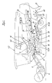
- FIG. 1 an executed as a combine harvester 2 agricultural harvester 1 is shown arranged at the front inclined conveyor 3 the harvested by an arbitrarily executed attachment 4 and merged into a crop strand 5 crop in its rear region to a threshing 6 passes.
- the crop strand 5 is conveyed in a manner known per se between one or more rotating threshing drums 7 and threshing and separating baskets 8, which wrap around them at least partially.
- the fruits are dissolved out of the fruit stalls and are separated to a considerable extent in the threshing and separating baskets 8 together with short straw and chaff as a first crop stream 9 and fed to a preparation tray 10 assigned to these threshing and separating baskets 8 at the bottom.
- a preparation tray 10 of this first Erntegutstrom 9 finally passes into a cleaning device 11, the means of vibrating screens 12 and blower 13 generated by air currents 14 a separation of the so-called non-grain components of the fruits, in the harvest of grain that would be the grains realized.
- the cleaned grains are in the simplest case conveyed away from the cleaning device 11 by means of conveying screws 15.
- Another Erntegutstrom 16 occurs in the rear region of the threshing device 6 from this and is supplied in the illustrated embodiment of a designed as Horden presentler 18 grain straw separating device 17.
- a further Erntegutstrom 19 is deposited in the lower side region of the grain-straw separator 17, which also consists essentially of grains, short straw and chaff.
- this Erntegutstrom 19 Via a arranged below the tray shaker 18 inclined return tray 20 of this Erntegutstrom 19 also passes into the cleaning device 11, wherein, as already described, the grains are separated from the non-grain components.
- this crop stream 21 essentially consisting of non-grain constituents such as straw and chaff.
- a small proportion of this Erntegutstromes 21 21 is formed by the loss of the harvester 1 embodying grains.
- the threshing 6, the grain-straw separator 17 and the cleaning device 11 separating devices 23 are deposited on which grain-containing Erntegutströme 9, 16, 19, 21, so that each of these Abscheideorgane 23 may be causally responsible for grain losses. Consequently, the invention described below using the example of the threshing device 6 and the Horden oftenlers 18 can be used in the same way also on the cleaning device 11 or only one of these Abscheideorgane 23 in order to achieve the effects described.
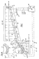
- Fig. 2 shows a detailed view of the threshing 6 with downstream Horden—ler 18.
- the threshing and Abscheidekörben 8 are assigned in their erntegutabscheidenden area 25 a plurality of known Abscheidesensoren 26, which are designed in the simplest case as rod sensors 27 and at least partially over the width of the threshing 6 extend.
- the separation sensors 26 arranged in the harvesting-depositing region 25 of the threshing device 6 are contacted more or less frequently as a function of the quantity of grains contained in the crop stream 9.
- the structure-borne noise generated thereby in the rod-shaped Abscheidesensoren 26 is used to determine the amount of deposited grains.
- the Abscheidesensoren 26 of this method are also referred to as so-called "knock sensors”.
- the separation sensors 30, 31 which in turn generate signals as a function of structure-borne noise, which are used to determine the quantity of separated grains can.
- the deposited in the separation sensors 26, 30 of the separated crop quantity adequate signals X1-X20 are transmitted via suitable data transmission systems 33 transmitted to the evaluation unit 34 according to the invention.
- suitable data transmission systems 33 transmitted to the evaluation unit 34 according to the invention.
- the Data transmission systems 33 lines or wireless transmission links can.
- a deposition efficiency value is determined AE1-AE20 determines a ratio between that in the respective deposition zone A1-A20 separated crop 19 and that of this separation zone A1-A20 supplied to be deposited crop amount, in the embodiment the grains 22, forms.
- these deposition efficiency values become AE1-AE20 in the evaluation unit 34 to a mean deposition efficiency value AEm summarized.
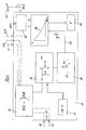
- the inventive method can be used flexibly, can in the evaluation unit 34 also several characteristics 38 as a function of different specific crop parameters, whereby the crop type and the moisture content of the crop is the most important crop-specific parameter are.
- those in the evaluation unit 34 stored characteristics 38 changeable or it can the evaluation 34 more Characteristic curves 38 are added.
- this is possible by that the driver of the harvester 1 defined over a certain period of time Erntegutmengen by means of the attachment 4 receives.
- the case from the rear Range of the combine 2 exiting crop 21 is thereby above per se known grain loss sensors 42 promoted.
- the from this Erntegutstrom 21 leaking grains 22 generate in the grain loss sensors 42 the grain mass adequate signals KS2.
- the harvester has 2 in known manner via a grain quantity sensor 43 in the simplest case in at least one grain elevator 44 of the combine harvester 2 is arranged and one of the generated by the combine harvester 2 total amount of seed adequate signal KS1 generated. In a first calculation step 45, these become adequate for the respective grain quantities Signals KS1, KS2 a loss value V determined, which then depends on the respectively determined according to the invention characteristics Y as a new or additional characteristic 38 is stored in the evaluation unit 34. It is within the scope of the invention the loss values V are also determined without in and from the harvester 1 itself to have been deposited in the evaluation unit 34.
Landscapes
- Life Sciences & Earth Sciences (AREA)
- Environmental Sciences (AREA)
- Management, Administration, Business Operations System, And Electronic Commerce (AREA)
- Threshing Machine Elements (AREA)
- Catching Or Destruction (AREA)
Abstract
Description
- Figur 1
- die schematische Seitenansicht eines Mähdreschers
- Figur 2
- eine Detailansicht des Mähdreschers nach Fig. 1 mit erfindungsgemäßen Abscheidesensoren und Auswerteinheit
- Figur 2a
- Detailansicht nach Figur 2
- Figur 3
- eine Funktionsschema der erfindungsgemäßen Auswerteinheit.
- Figur 4
- ein weiteres Funktionsschema der erfindungsgemäßen Auswerteinheit.
Ein weiterer Erntegutstrom 16 tritt im rückwärtigen Bereich der Drescheinrichtung 6 aus dieser aus und wird im dargestellten Ausführungsbeispiel einer als Hordenschüttler 18 ausgeführten Korn-Stroh-Trenneinrichtung 17 zugeführt. Während der Bewegung dieses Erntegutstromes 16 auf der Korn-Stroh-Trenneinrichtung 17 wird ein weiterer Erntegutstrom 19 im untenseitigen Bereich der Korn-Stroh-Trenneinrichtung 17 abgeschieden, der im Wesentlichen ebenfalls aus Körnern, Kurzstroh und Spreu besteht. Über einen unterhalb des Hordenschüttlers 18 angeordneten geneigten Rücklaufboden 20 gelangt dieser Erntegutstrom 19 ebenfalls in die Reinigungseinrichtung 11, wobei, wie bereits beschrieben, die Körner von den Nichtkornbestandteilen getrennt werden.
Im rückwärtigen Bereich des Mähdreschers werden die nicht verwertbaren Anteile der verschiedenen Erntegutströme 9, 16, 19 aus dem Mähdrescher 2 herausgefördert, wobei dieser Erntegutstrom 21 im Wesentlichen aus Nichtkornbestandteilen wie Stroh und Spreu besteht. Ein geringer Anteil dieses Erntegutstromes 21 wird jedoch von den Verlust der Erntemaschine 1 verkörpernden Körner 22 gebildet.
Im dargestellten Ausführungsbeispiel bilden das Dreschwerk 6, die Korn-Stroh-Trenneinrichtung 17 und die Reinigungseinrichtung 11 Abscheideorgane 23 an denen körnerhaltige Erntegutströme 9, 16, 19, 21 abgeschieden werden, sodass jedes dieser Abscheideorgane 23 ursächlich für Kornverluste verantwortlich sein kann. Folglich kann die nachfolgend am Beispiel der Drescheinrichtung 6 und des Hordenschüttlers 18 beschriebene Erfindung in gleicher Weise auch an der Reinigungseinrichtung 11 oder nur einem dieser Abscheideorgane 23 eingesetzt werden, um die beschriebenen Effekte zu erzielen. Zudem liegt es im Rahmen der Erfindung, das zu beschreibende Verfahren auf Mähdrescher 2 anzuwenden, die an Stelle des Hordenschüttlers 18 einen Axialtrennrotor 24 aufweisen oder deren Dresch- und Trenneinrichtungen 6, 17 durch an sich bekannte und nicht näher dargestellte Dresch- und Trennrotoren ersetzt sind.
Ferner sind dem Hordenschüttler 18 unterhalb seiner Trennfläche 28 in seinem erntegutabscheidenden Bereich 29 ebenfalls eine Vielzahl von Abscheidesensoren 30 zugeordnet, die einfachstenfalls auch als Stabsensoren 31 ausgeführt sein können und sich zumindest über einen Teil der Breite der Korn-Stroh-Trenneinrichtung 17 erstrecken. Auch hier kommt es beim Durchtreten des im Bereich des Hordenschüttlers 18 abgeschiedenen Erntegutstromes 19 zum Auftreffen der in dem Erntegutstrom 19 befindlichen Körner 22 auf die Abscheidesensoren 30, 31 die dann wiederum in Abhängigkeit vom Körperschall Signale generieren, die zur Ermittlung der Menge abgeschiedener Körner herangezogen werden können.
- 1
- Erntemaschine
- 2
- Mähdrescher
- 3
- Schrägförderer
- 4
- Vorsatzgerät
- 5
- Erntegutstrang
- 6
- Dreschwerk
- 7
- Dreschtrommel
- 8
- Dresch- und Abscheidekorb
- 9
- Erntegutstrom
- 10
- Vorbereitungsboden
- 11
- Reinigungseinrichtung
- 12
- Sieb
- 13
- Gebläse
- 14
- Luftströmung
- 15
- Förderschnecke
- 16
- Erntegutstrom
- 17
- Korn-Stroh-Trenneinrichtung
- 18
- Hordenschüttler
- 19
- Erntegutstrom
- 20
- Rücklaufboden
- 21
- Erntegutstrom
- 22
- Körner
- 23
- Abscheideorgane
- 24
- Axialtrennrotor
- 25
- erntegutabscheidender Bereich
- 26
- Abscheidesensoren
- 27
- Stabsensoren
- 28
- Trennfläche
- 29
- erntegutabscheidender Bereich
- 30
- Abscheidesensor
- 31
- Stabsensor
- 32
- Quersteg
- 33
- Datenübertragungssystem
- 34
- Auswerteinheit
- 35
- Rechenschritt
- 36
- Rechenschritt
- 37
- Rechenschritt
- 38
- Kennlinie
- 39
- Rechenschritt
- 40
- Anzeige
- 41
- Blockbild
- 42
- Kornverlustsensor
- 43
- Kornmengensensorik
- 44
- Kornelevator
- 45
- Rechenschritt
- AE
- Abscheideeffizienzwert
- AEm
- mittlerer Abscheideeffizienzwert
- AV
- Abscheideverlauf
- A1-20
- Abscheidezone
- KS1
- Körnermassesignal
- KS2
- Körnermassesignal
- L
- Abscheidelänge
- V
- Verlustwert
- VM
- Verlustmasse
- X
- Erntegutmengensignal
- Xa..c
- Erntegutmengensignal
- Y
- Kenngröße
Claims (15)
- Verfahren zur Bestimmung des Verlustes einer Erntemaschine, mit einem oder mehreren Abscheideorganen, wobei dem oder den Abscheideorganen in ihrem erntegutabscheidenden Bereich zumindest ein Abscheidesensor zur Generierung zumindest eines der abgeschiedenen Erntegutmenge adäquaten Signals zugeordnet ist und dieses zumindest eine Signal zur Weiterverarbeitung einer Auswerteinheit zugeführt wird,
dadurch gekennzeichnet, dass der erntegutabscheidende Bereich (25, 29) des wenigstens einen Abscheideorgans (6, 11, 17, 23) oder der mehreren Abscheideorgane (6, 11, 17, 23) in Abscheidezonen (A1-A20) unterteilt ist, wobei der Abscheideverlauf (AV) zumindest eines Teils der Abscheidezonen (A1-A20) ermittelt und zu einer Kenngröße (Y) verrechnet wird und für diese ermittelte Kenngröße (Y) in der Auswerteinheit (34) zumindest eine Kennlinie (38) hinterlegt ist aus der sich der der ermittelten Kenngröße (Y) entsprechende Verlust (V) ergibt. - Verfahren zur Bestimmung der Verluste einer Erntemaschine nach Anspruch 1,
dadurch gekennzeichnet, dass die über der in Gutaustragrichtung letzten Abscheidezone (A20) nicht abgeschiedene, die Verlustmasse (VM) bildende Erntegutmenge (22) vernachlässigt und eine vollständige Abscheidung in dieser letzten Abscheidezone (A20) angenommen wird. - Verfahren zur Bestimmung der Verluste einer Erntemaschine nach einem oder mehreren Ansprüche,
dadurch gekennzeichnet, dass der erntegutabscheidende Bereich (25, 29) des oder der Abscheideorgane (6, 11, 17, 23) in aneinandergrenzende Abscheidezonen (A1-A20) unterteilt ist und jeder Abscheidezone (A1-A20) zumindest ein Abscheidesensor (26, 30) zur Generierung zumindest eines der abgeschiedenen Erntegutmenge (9, 19) adäquaten Signals (X1-X20, Xa..c) zugeordnet ist. - Verfahren zur Bestimmung der Verluste einer Erntemaschine nach einem oder mehreren der vorhergehenden Ansprüche,
dadurch gekennzeichnet, dass die der abgeschiedenen Erntegutmenge (9, 19) adäquaten Signale (X1-X20, Xa..c) einer Abscheidezone (A1-A20) in der Auswerteinheit (34) zu einem Abscheideeffizienzwert (AE) verrechnet werden. - Verfahren zur Bestimmung der Verluste einer Erntemaschine nach einem oder mehreren der vorhergehenden Ansprüche,
dadurch gekennzeichnet, dass der Abscheideeffizienzwert (AE) durch Integration des Abscheideverlaufs (AV) innerhalb der jeweiligen Abscheidezone (A1-A20) ermittelt wird und sich aus dem Verhältnis zwischen dem über der jeweiligen Abscheidezone (A1-A20) abgeschiedenen Erntegutmenge (9, 19) und der dieser Abscheidezone (A1-A20) zugeführten abzuscheidenden Erntegutmenge (22) ergibt. - Verfahren zur Bestimmung der Verluste einer Erntemaschine nach einem oder mehreren der vorhergehenden Ansprüche,
dadurch gekennzeichnet, dass die Abscheideeffizienzwerte (AE) zumindest eines Teils der Abscheidezonen (A1-A20) zu einem mittleren Abscheideeffizienzwert (AEm) verrechnet werden und dieser mittlere Abscheideeffizienzwert (AEm) die Kenngröße (Y) zur Ermittlung des Verlustwertes (V) bildet. - Verfahren zur Bestimmung der Verluste einer Erntemaschine nach einem oder mehreren der vorhergehenden Ansprüche,
dadurch gekennzeichnet, dass die in der Auswerteinheit (34) hinterlegte zumindest eine Kennlinien (38) den Verlust (V) in Abhängigkeit vom mittleren Abscheideeffizienzwert (AEm) darstellt. - Verfahren zur Bestimmung der Verluste einer Erntemaschine nach Anspruch 7,
dadurch gekennzeichnet, dass die wenigstens eine Kennlinie (38) in Abhängigkeit von erntegutspezifischen Parametern hinterlegt ist. - Verfahren zur Bestimmung der Verluste einer Erntemaschine nach Anspruch 8,
dadurch gekennzeichnet, dass die erntegutspezifischen Parameter die Gutart und/oder die Erntegutfeuchte sein können. - Verfahren zur Bestimmung der Verluste einer Erntemaschine nach einem oder mehreren der vorhergehenden Ansprüche,
dadurch gekennzeichnet, dass in der Auswerteinheit (34) eine Vielzahl von Kennlinien (38) hinterlegt sind. - Verfahren zur Bestimmung der Verluste einer Erntemaschine nach einem oder mehreren der vorhergehenden Ansprüche,
dadurch gekennzeichnet, dass die in der Auswerteinheit (34) hinterlegten Kennlinien (38) änderbar sind. - Verfahren zur Bestimmung der Verluste einer Erntemaschine nach Anspruch 11,
dadurch gekennzeichnet, dass zur Änderung der Kennlinien (38) die der abgeschiedenen Erntegutmenge (9, 19) adäquaten Signale (X1-X20, Xa..c) der Abscheidesensoren (26, 30) in Abhängigkeit von verschiedenen Erntegutdurchsätzen in der Auswerteinheit (34) zu mittleren Abscheideeffizienzwerten (AEm) verrechnet werden, wobei jeweils Verlustwerte (V) und mittlere Abscheideeffizienzwerte (AEm) eines Durchsatzes ein Wertepaar der neu zu generierenden Kennlinie (38) bilden. - Verfahren zur Bestimmung der Verluste einer Erntemaschine nach Anspruch 12,
dadurch gekennzeichnet, dass die den mittleren Abscheideeffizienzwerten (AEm) zugeordneten Verlustwerte (V) auf der Erntemaschine (1, 2) und/oder separat von dieser ermittelt und in der Auswerteinheit (34) hinterlegt werden. - Vorrichtung zur Durchführung des Verfahrens zur Bestimmung des Verlustes einer Erntemaschine nach Anspruch 1,
dadurch gekennzeichnet, dass dem oder den Arbeitsorganen (6, 11, 17, 23) ein oder mehrere Abscheidesensoren (26, 30) im erntegutabscheidenden Bereich (25, 29) zugeordnet sind, die mittels Datenübertragungsystemen (33) mit einer Auswerteinheit (34) in Wirkverbindung stehen, wobei die Abscheidesensoren (26, 30) den erntegutabscheidenden Bereich (25, 29) in voneinander getrennte Abscheidezonen (A1-A20) unterteilen. - Vorrichtung zur Bestimmung des Verlustes einer Erntemaschine nach Anspruch 14,
dadurch gekennzeichnet, dass die voneinander getrennten Abscheidezonen (A1-A20) durch ortsfeste Trennelemente (32) und/oder software-seitig in der Auswerteinheit (34) voneinander abgegrenzt sind.
Applications Claiming Priority (2)
| Application Number | Priority Date | Filing Date | Title |
|---|---|---|---|
| DE10162354 | 2001-12-18 | ||
| DE10162354A DE10162354A1 (de) | 2001-12-18 | 2001-12-18 | Verfahren zur Verlustbestimmung an landwirtschaftlichen Erntemaschinen |
Publications (2)
| Publication Number | Publication Date |
|---|---|
| EP1321023A1 true EP1321023A1 (de) | 2003-06-25 |
| EP1321023B1 EP1321023B1 (de) | 2009-02-25 |
Family
ID=7709779
Family Applications (1)
| Application Number | Title | Priority Date | Filing Date |
|---|---|---|---|
| EP02026556A Expired - Lifetime EP1321023B1 (de) | 2001-12-18 | 2002-11-28 | Verfahren zur Verlustbestimmung an landwirtschaftlichen Erntemaschinen |
Country Status (4)
| Country | Link |
|---|---|
| US (1) | US6869355B2 (de) |
| EP (1) | EP1321023B1 (de) |
| AT (1) | ATE423453T1 (de) |
| DE (2) | DE10162354A1 (de) |
Cited By (6)
| Publication number | Priority date | Publication date | Assignee | Title |
|---|---|---|---|---|
| EP1470749A1 (de) * | 2003-04-22 | 2004-10-27 | CLAAS Selbstfahrende Erntemaschinen GmbH | Dresch-/Separator-System |
| EP3141102A1 (de) * | 2015-09-10 | 2017-03-15 | Deere & Company | Erweiterte ernteverlusterfassung |
| EP3150058A1 (de) * | 2015-10-01 | 2017-04-05 | CLAAS Selbstfahrende Erntemaschinen GmbH | Mähdrescher |
| EP3662737A1 (de) * | 2018-12-07 | 2020-06-10 | CLAAS Selbstfahrende Erntemaschinen GmbH | Selbstfahrender mähdrescher |
| EP4696126A1 (de) * | 2024-08-12 | 2026-02-18 | CLAAS Selbstfahrende Erntemaschinen GmbH | Verteilvorrichtung für einen mähdrescher |
| EP4714251A1 (de) * | 2024-09-23 | 2026-03-25 | CLAAS Selbstfahrende Erntemaschinen GmbH | Verfahren zum bestimmen einer sensorposition in einem abscheideorgan einer erntemaschine |
Families Citing this family (17)
| Publication number | Priority date | Publication date | Assignee | Title |
|---|---|---|---|---|
| DE10360597A1 (de) * | 2003-12-19 | 2005-07-28 | Claas Selbstfahrende Erntemaschinen Gmbh | Verfahren und Vorrichtung zur Regelung von Arbeitsorganen eines Mähdreschers |
| AR046597A1 (es) | 2004-10-21 | 2005-12-14 | Ariel Gustavo Melano | Disposicion para reducir perdidas por desgrane en cabezales sojeros |
| DE102007029218A1 (de) * | 2007-06-22 | 2008-12-24 | Claas Selbstfahrende Erntemaschinen Gmbh | Selbstfahrende landwirtschaftliche Erntemaschine mit Verlustmesseinrichtung |
| FR2958911B1 (fr) * | 2010-04-19 | 2012-04-27 | Snecma | Procede et systeme de surveillance du niveau d'huile contenue dans un reservoir d'un moteur d'aeronef |
| DE102010017687A1 (de) * | 2010-07-01 | 2012-01-05 | Claas Selbstfahrende Erntemaschinen Gmbh | Verfahren zur Einstellung zumindest eines Arbeitsorganes einer selbstfahrenden Erntemaschine |
| DE102011052282A1 (de) * | 2011-07-29 | 2013-01-31 | Claas Selbstfahrende Erntemaschinen Gmbh | Reinigungssensor zur Steuerung der Erntegut- und Gebläsedruckverteilung |
| US8821229B2 (en) | 2012-12-06 | 2014-09-02 | Cnh Industrial America Llc | Grain cleaning system for an agricultural combine |
| DE102013214984A1 (de) | 2013-07-31 | 2015-02-05 | Deere & Company | Anordnung zur Verlustmessung in einem Mähdrescher |
| GB201322403D0 (en) * | 2013-12-18 | 2014-02-05 | Agco As | Combine harvester grain cleaning system |
| US9526211B2 (en) * | 2014-02-28 | 2016-12-27 | Cnh Industrial America Llc | System and method of controlling airflow characteristics in an agricultural harvester |
| DE102015102056A1 (de) * | 2015-02-12 | 2016-08-18 | Claas Selbstfahrende Erntemaschinen Gmbh | Verfahren zur Bestimmung von Kalibrierungsdaten für einen Kornverlustsensor |
| BR112020010680A2 (pt) * | 2018-03-05 | 2020-11-10 | Agco Corporation | máquina de colheita com sistema de visualização |
| US11013175B2 (en) | 2018-07-26 | 2021-05-25 | Deere & Company | Grain loss apparatus for a grain harvesting vehicle |
| EP3714674B1 (de) * | 2019-03-28 | 2023-09-06 | CNH Industrial Belgium NV | Strohschüttlerlastüberwachung |
| CN110622684B (zh) * | 2019-10-22 | 2020-12-29 | 山东理工大学 | 一种谷物收获机籽粒损失检测方法和系统 |
| US12310285B2 (en) | 2023-02-27 | 2025-05-27 | Deere & Company | Agricultural operation evaluation system and method |
| DE102024124584A1 (de) | 2024-08-28 | 2026-03-05 | Claas Selbstfahrende Erntemaschinen Gmbh | Verfahren zum Bestimmen eines Verlusts einer Erntemaschine und Erntemaschine |
Citations (5)
| Publication number | Priority date | Publication date | Assignee | Title |
|---|---|---|---|---|
| US4360998A (en) * | 1981-03-27 | 1982-11-30 | Sperry Corporation | Absolute grain loss monitor |
| EP0347979A1 (de) * | 1988-06-23 | 1989-12-27 | New Holland Belgium N.V. | Fahrgeschwindigkeits-Überwachungssystem für Mähdrescher |
| US5015997A (en) * | 1988-04-26 | 1991-05-14 | Ford New Holland, Inc. | Method and apparatus for measuring combine grain loss |
| EP0728409A1 (de) * | 1995-02-22 | 1996-08-28 | Deere & Company | Verfahren zur automatischen Regelung wenigstens eines Abschnitts der Gutbearbeitung in einer Erntemaschine |
| DE19807145A1 (de) * | 1998-02-20 | 1999-09-02 | Claas Selbstfahr Erntemasch | Mähdrescher mit Vorrichtung zur automatischen Reinigungseinstellung |
Family Cites Families (3)
| Publication number | Priority date | Publication date | Assignee | Title |
|---|---|---|---|---|
| DE3874325T2 (de) | 1988-04-26 | 1993-02-25 | Ford New Holland Inc | Prall-detektoren. |
| DE19800238C1 (de) * | 1998-01-07 | 1999-08-26 | Claas Selbstfahr Erntemasch | System zur Einstellung einer selbstfahrenden Erntemaschine |
| DE19921466A1 (de) * | 1999-05-08 | 2000-11-09 | Deere & Co | Einrichtung zum Regeln der Vortriebsgeschwindigkeit einer Erntemaschine mit unscharfer Logik |
-
2001
- 2001-12-18 DE DE10162354A patent/DE10162354A1/de not_active Withdrawn
-
2002
- 2002-11-28 EP EP02026556A patent/EP1321023B1/de not_active Expired - Lifetime
- 2002-11-28 DE DE50213311T patent/DE50213311D1/de not_active Expired - Lifetime
- 2002-11-28 AT AT02026556T patent/ATE423453T1/de not_active IP Right Cessation
- 2002-12-18 US US10/322,927 patent/US6869355B2/en not_active Expired - Lifetime
Patent Citations (5)
| Publication number | Priority date | Publication date | Assignee | Title |
|---|---|---|---|---|
| US4360998A (en) * | 1981-03-27 | 1982-11-30 | Sperry Corporation | Absolute grain loss monitor |
| US5015997A (en) * | 1988-04-26 | 1991-05-14 | Ford New Holland, Inc. | Method and apparatus for measuring combine grain loss |
| EP0347979A1 (de) * | 1988-06-23 | 1989-12-27 | New Holland Belgium N.V. | Fahrgeschwindigkeits-Überwachungssystem für Mähdrescher |
| EP0728409A1 (de) * | 1995-02-22 | 1996-08-28 | Deere & Company | Verfahren zur automatischen Regelung wenigstens eines Abschnitts der Gutbearbeitung in einer Erntemaschine |
| DE19807145A1 (de) * | 1998-02-20 | 1999-09-02 | Claas Selbstfahr Erntemasch | Mähdrescher mit Vorrichtung zur automatischen Reinigungseinstellung |
Cited By (8)
| Publication number | Priority date | Publication date | Assignee | Title |
|---|---|---|---|---|
| EP1470749A1 (de) * | 2003-04-22 | 2004-10-27 | CLAAS Selbstfahrende Erntemaschinen GmbH | Dresch-/Separator-System |
| EP3141102A1 (de) * | 2015-09-10 | 2017-03-15 | Deere & Company | Erweiterte ernteverlusterfassung |
| US10729065B2 (en) | 2015-09-10 | 2020-08-04 | Deere & Company | Augmented crop loss sensing |
| US12342750B2 (en) | 2015-09-10 | 2025-07-01 | Deere & Company | Augmented crop loss sensing |
| EP3150058A1 (de) * | 2015-10-01 | 2017-04-05 | CLAAS Selbstfahrende Erntemaschinen GmbH | Mähdrescher |
| EP3662737A1 (de) * | 2018-12-07 | 2020-06-10 | CLAAS Selbstfahrende Erntemaschinen GmbH | Selbstfahrender mähdrescher |
| EP4696126A1 (de) * | 2024-08-12 | 2026-02-18 | CLAAS Selbstfahrende Erntemaschinen GmbH | Verteilvorrichtung für einen mähdrescher |
| EP4714251A1 (de) * | 2024-09-23 | 2026-03-25 | CLAAS Selbstfahrende Erntemaschinen GmbH | Verfahren zum bestimmen einer sensorposition in einem abscheideorgan einer erntemaschine |
Also Published As
| Publication number | Publication date |
|---|---|
| US6869355B2 (en) | 2005-03-22 |
| DE10162354A1 (de) | 2003-07-03 |
| US20030199291A1 (en) | 2003-10-23 |
| EP1321023B1 (de) | 2009-02-25 |
| ATE423453T1 (de) | 2009-03-15 |
| DE50213311D1 (de) | 2009-04-09 |
Similar Documents
| Publication | Publication Date | Title |
|---|---|---|
| EP1321023B1 (de) | Verfahren zur Verlustbestimmung an landwirtschaftlichen Erntemaschinen | |
| EP1516522B1 (de) | Verfahren und Vorrichtung zur Ermittlung der Überkehrerntegutmenge | |
| EP3613272B1 (de) | Mähdrescher | |
| EP1543712B1 (de) | Verfahren und Vorrichtung zur Regelung von Arbeitsorganen eines Mähdreschers | |
| EP2057882B1 (de) | Verfahren zur Qualitätsüberwachung von Erntegut | |
| EP1769667B1 (de) | Selbstfahrende Erntemaschine und Betriebsverfahren dafür | |
| DE3850570T2 (de) | Verfahren und Vorrichtung zur Körnerverlustmessung an Dreschmaschinen. | |
| EP1741329B1 (de) | Verfahren und Vorrichtung zur Optimierung von Betriebsparametern einer landwirtschaftlichen Arbeitsmaschine | |
| EP0728409B1 (de) | Verfahren zur automatischen Regelung wenigstens eines Abschnitts der Gutbearbeitung in einer Erntemaschine | |
| DE102005043991A1 (de) | Verfahren zur Einstellung eines Arbeitsaggregats einer Erntemaschine | |
| DE10147733A1 (de) | Verfahren und Vorrichtung zur Ermittlung einer Erntemaschineneinstellung | |
| DE10307705A1 (de) | Verfahren und Vorrichtung zum Trennen eines Erntegutstroms | |
| DE102011052280A1 (de) | Vermeidung von Reinigungsverlusten bei starker Seitenneigung | |
| EP3797575A1 (de) | Mähdrescher und fahrerassistenzsystem dafür | |
| EP2168419B1 (de) | Landwirtschaftliche Erntemaschine | |
| EP1584225B1 (de) | Mähdrescher | |
| EP4151072A1 (de) | Abscheideeinrichtung für einen mähdrescher sowie mähdrescher mit einer solchen abscheideeinrichtung | |
| EP3797577B1 (de) | Mähdrescher mit restkornsensor | |
| EP1479280A1 (de) | Vorrichtung und Verfahren zum Trennen eines Erntegutstroms | |
| EP2805602B1 (de) | Mähdrescher | |
| EP3459337B1 (de) | Landwirtschaftliche arbeitsmaschine | |
| EP3150058B1 (de) | Mähdrescher | |
| DE102006044159A1 (de) | Anzeigeeinheit einer landwirtschaftlichen Arbeitsmaschine | |
| DE102021110556A1 (de) | Mähdrescher sowie Verfahren zum Betreiben eines Mähdreschers | |
| DE2913657A1 (de) | Erntemaschine zur gewinnung von tierfutter (corn-cop-mix) aus maiskolben |
Legal Events
| Date | Code | Title | Description |
|---|---|---|---|
| PUAI | Public reference made under article 153(3) epc to a published international application that has entered the european phase |
Free format text: ORIGINAL CODE: 0009012 |
|
| AK | Designated contracting states |
Designated state(s): AT BE BG CH CY CZ DE DK EE ES FI FR GB GR IE IT LI LU MC NL PT SE SK TR |
|
| AX | Request for extension of the european patent |
Extension state: AL LT LV MK RO SI |
|
| 17P | Request for examination filed |
Effective date: 20031229 |
|
| AKX | Designation fees paid |
Designated state(s): AT BE BG CH CY CZ DE DK EE ES FI FR GB GR IE IT LI LU MC NL PT SE SK TR |
|
| 17Q | First examination report despatched |
Effective date: 20070820 |
|
| GRAP | Despatch of communication of intention to grant a patent |
Free format text: ORIGINAL CODE: EPIDOSNIGR1 |
|
| RTI1 | Title (correction) |
Free format text: METHOD OF DETERMINING THE LOSS IN AGRICULTURAL MACHINES |
|
| GRAS | Grant fee paid |
Free format text: ORIGINAL CODE: EPIDOSNIGR3 |
|
| GRAA | (expected) grant |
Free format text: ORIGINAL CODE: 0009210 |
|
| AK | Designated contracting states |
Kind code of ref document: B1 Designated state(s): AT BE BG CH CY CZ DE DK EE ES FI FR GB GR IE IT LI LU MC NL PT SE SK TR |
|
| REG | Reference to a national code |
Ref country code: GB Ref legal event code: FG4D Free format text: NOT ENGLISH |
|
| REG | Reference to a national code |
Ref country code: CH Ref legal event code: EP |
|
| REG | Reference to a national code |
Ref country code: IE Ref legal event code: FG4D Free format text: LANGUAGE OF EP DOCUMENT: GERMAN |
|
| REF | Corresponds to: |
Ref document number: 50213311 Country of ref document: DE Date of ref document: 20090409 Kind code of ref document: P |
|
| PG25 | Lapsed in a contracting state [announced via postgrant information from national office to epo] |
Ref country code: FI Free format text: LAPSE BECAUSE OF FAILURE TO SUBMIT A TRANSLATION OF THE DESCRIPTION OR TO PAY THE FEE WITHIN THE PRESCRIBED TIME-LIMIT Effective date: 20090225 Ref country code: NL Free format text: LAPSE BECAUSE OF FAILURE TO SUBMIT A TRANSLATION OF THE DESCRIPTION OR TO PAY THE FEE WITHIN THE PRESCRIBED TIME-LIMIT Effective date: 20090225 |
|
| NLV1 | Nl: lapsed or annulled due to failure to fulfill the requirements of art. 29p and 29m of the patents act | ||
| PG25 | Lapsed in a contracting state [announced via postgrant information from national office to epo] |
Ref country code: SE Free format text: LAPSE BECAUSE OF FAILURE TO SUBMIT A TRANSLATION OF THE DESCRIPTION OR TO PAY THE FEE WITHIN THE PRESCRIBED TIME-LIMIT Effective date: 20090525 |
|
| REG | Reference to a national code |
Ref country code: IE Ref legal event code: FD4D |
|
| PG25 | Lapsed in a contracting state [announced via postgrant information from national office to epo] |
Ref country code: IE Free format text: LAPSE BECAUSE OF FAILURE TO SUBMIT A TRANSLATION OF THE DESCRIPTION OR TO PAY THE FEE WITHIN THE PRESCRIBED TIME-LIMIT Effective date: 20090225 Ref country code: ES Free format text: LAPSE BECAUSE OF FAILURE TO SUBMIT A TRANSLATION OF THE DESCRIPTION OR TO PAY THE FEE WITHIN THE PRESCRIBED TIME-LIMIT Effective date: 20090605 Ref country code: DK Free format text: LAPSE BECAUSE OF FAILURE TO SUBMIT A TRANSLATION OF THE DESCRIPTION OR TO PAY THE FEE WITHIN THE PRESCRIBED TIME-LIMIT Effective date: 20090225 Ref country code: CZ Free format text: LAPSE BECAUSE OF FAILURE TO SUBMIT A TRANSLATION OF THE DESCRIPTION OR TO PAY THE FEE WITHIN THE PRESCRIBED TIME-LIMIT Effective date: 20090225 Ref country code: PT Free format text: LAPSE BECAUSE OF FAILURE TO SUBMIT A TRANSLATION OF THE DESCRIPTION OR TO PAY THE FEE WITHIN THE PRESCRIBED TIME-LIMIT Effective date: 20090812 Ref country code: EE Free format text: LAPSE BECAUSE OF FAILURE TO SUBMIT A TRANSLATION OF THE DESCRIPTION OR TO PAY THE FEE WITHIN THE PRESCRIBED TIME-LIMIT Effective date: 20090225 |
|
| PG25 | Lapsed in a contracting state [announced via postgrant information from national office to epo] |
Ref country code: SK Free format text: LAPSE BECAUSE OF FAILURE TO SUBMIT A TRANSLATION OF THE DESCRIPTION OR TO PAY THE FEE WITHIN THE PRESCRIBED TIME-LIMIT Effective date: 20090225 |
|
| PLBE | No opposition filed within time limit |
Free format text: ORIGINAL CODE: 0009261 |
|
| STAA | Information on the status of an ep patent application or granted ep patent |
Free format text: STATUS: NO OPPOSITION FILED WITHIN TIME LIMIT |
|
| PG25 | Lapsed in a contracting state [announced via postgrant information from national office to epo] |
Ref country code: BG Free format text: LAPSE BECAUSE OF FAILURE TO SUBMIT A TRANSLATION OF THE DESCRIPTION OR TO PAY THE FEE WITHIN THE PRESCRIBED TIME-LIMIT Effective date: 20090525 |
|
| 26N | No opposition filed |
Effective date: 20091126 |
|
| PG25 | Lapsed in a contracting state [announced via postgrant information from national office to epo] |
Ref country code: MC Free format text: LAPSE BECAUSE OF NON-PAYMENT OF DUE FEES Effective date: 20091130 |
|
| REG | Reference to a national code |
Ref country code: CH Ref legal event code: PL |
|
| PG25 | Lapsed in a contracting state [announced via postgrant information from national office to epo] |
Ref country code: GR Free format text: LAPSE BECAUSE OF FAILURE TO SUBMIT A TRANSLATION OF THE DESCRIPTION OR TO PAY THE FEE WITHIN THE PRESCRIBED TIME-LIMIT Effective date: 20090526 Ref country code: CH Free format text: LAPSE BECAUSE OF NON-PAYMENT OF DUE FEES Effective date: 20091130 Ref country code: LI Free format text: LAPSE BECAUSE OF NON-PAYMENT OF DUE FEES Effective date: 20091130 |
|
| PG25 | Lapsed in a contracting state [announced via postgrant information from national office to epo] |
Ref country code: AT Free format text: LAPSE BECAUSE OF NON-PAYMENT OF DUE FEES Effective date: 20091128 |
|
| PG25 | Lapsed in a contracting state [announced via postgrant information from national office to epo] |
Ref country code: LU Free format text: LAPSE BECAUSE OF NON-PAYMENT OF DUE FEES Effective date: 20091128 |
|
| PG25 | Lapsed in a contracting state [announced via postgrant information from national office to epo] |
Ref country code: TR Free format text: LAPSE BECAUSE OF FAILURE TO SUBMIT A TRANSLATION OF THE DESCRIPTION OR TO PAY THE FEE WITHIN THE PRESCRIBED TIME-LIMIT Effective date: 20090225 |
|
| PG25 | Lapsed in a contracting state [announced via postgrant information from national office to epo] |
Ref country code: CY Free format text: LAPSE BECAUSE OF FAILURE TO SUBMIT A TRANSLATION OF THE DESCRIPTION OR TO PAY THE FEE WITHIN THE PRESCRIBED TIME-LIMIT Effective date: 20090225 |
|
| REG | Reference to a national code |
Ref country code: FR Ref legal event code: PLFP Year of fee payment: 14 |
|
| REG | Reference to a national code |
Ref country code: FR Ref legal event code: PLFP Year of fee payment: 15 |
|
| REG | Reference to a national code |
Ref country code: FR Ref legal event code: PLFP Year of fee payment: 16 |
|
| PGFP | Annual fee paid to national office [announced via postgrant information from national office to epo] |
Ref country code: FR Payment date: 20171121 Year of fee payment: 16 |
|
| PGFP | Annual fee paid to national office [announced via postgrant information from national office to epo] |
Ref country code: GB Payment date: 20171123 Year of fee payment: 16 |
|
| GBPC | Gb: european patent ceased through non-payment of renewal fee |
Effective date: 20181128 |
|
| REG | Reference to a national code |
Ref country code: DE Ref legal event code: R084 Ref document number: 50213311 Country of ref document: DE |
|
| PG25 | Lapsed in a contracting state [announced via postgrant information from national office to epo] |
Ref country code: FR Free format text: LAPSE BECAUSE OF NON-PAYMENT OF DUE FEES Effective date: 20181130 |
|
| PG25 | Lapsed in a contracting state [announced via postgrant information from national office to epo] |
Ref country code: GB Free format text: LAPSE BECAUSE OF NON-PAYMENT OF DUE FEES Effective date: 20181128 |
|
| PGFP | Annual fee paid to national office [announced via postgrant information from national office to epo] |
Ref country code: DE Payment date: 20190930 Year of fee payment: 18 |
|
| PGFP | Annual fee paid to national office [announced via postgrant information from national office to epo] |
Ref country code: IT Payment date: 20191128 Year of fee payment: 18 Ref country code: BE Payment date: 20191120 Year of fee payment: 18 |
|
| REG | Reference to a national code |
Ref country code: DE Ref legal event code: R119 Ref document number: 50213311 Country of ref document: DE |
|
| REG | Reference to a national code |
Ref country code: BE Ref legal event code: MM Effective date: 20201130 |
|
| PG25 | Lapsed in a contracting state [announced via postgrant information from national office to epo] |
Ref country code: IT Free format text: LAPSE BECAUSE OF NON-PAYMENT OF DUE FEES Effective date: 20201128 |
|
| PG25 | Lapsed in a contracting state [announced via postgrant information from national office to epo] |
Ref country code: DE Free format text: LAPSE BECAUSE OF NON-PAYMENT OF DUE FEES Effective date: 20210601 |
|
| PG25 | Lapsed in a contracting state [announced via postgrant information from national office to epo] |
Ref country code: BE Free format text: LAPSE BECAUSE OF NON-PAYMENT OF DUE FEES Effective date: 20201130 |