EP1320457B1 - Method for forming in-mold decorated article - Google Patents
Method for forming in-mold decorated article Download PDFInfo
- Publication number
- EP1320457B1 EP1320457B1 EP01977858.8A EP01977858A EP1320457B1 EP 1320457 B1 EP1320457 B1 EP 1320457B1 EP 01977858 A EP01977858 A EP 01977858A EP 1320457 B1 EP1320457 B1 EP 1320457B1
- Authority
- EP
- European Patent Office
- Prior art keywords
- polymeric material
- blowing agent
- substrate
- mold
- polymeric
- Prior art date
- Legal status (The legal status is an assumption and is not a legal conclusion. Google has not performed a legal analysis and makes no representation as to the accuracy of the status listed.)
- Expired - Lifetime
Links
- 238000000034 method Methods 0.000 title claims description 56
- 239000000463 material Substances 0.000 claims description 148
- 239000004604 Blowing Agent Substances 0.000 claims description 96
- 239000000758 substrate Substances 0.000 claims description 84
- 239000000203 mixture Substances 0.000 claims description 31
- 239000004744 fabric Substances 0.000 claims description 24
- CURLTUGMZLYLDI-UHFFFAOYSA-N Carbon dioxide Chemical compound O=C=O CURLTUGMZLYLDI-UHFFFAOYSA-N 0.000 claims description 17
- IJGRMHOSHXDMSA-UHFFFAOYSA-N Atomic nitrogen Chemical compound N#N IJGRMHOSHXDMSA-UHFFFAOYSA-N 0.000 claims description 11
- 229910002092 carbon dioxide Inorganic materials 0.000 claims description 11
- 238000000465 moulding Methods 0.000 claims description 11
- 239000012530 fluid Substances 0.000 claims description 10
- 239000004743 Polypropylene Substances 0.000 claims description 7
- 239000001569 carbon dioxide Substances 0.000 claims description 6
- 229910052757 nitrogen Inorganic materials 0.000 claims description 6
- -1 polypropylene Polymers 0.000 claims description 6
- 229920001169 thermoplastic Polymers 0.000 claims description 6
- 238000002156 mixing Methods 0.000 claims description 5
- 229920001155 polypropylene Polymers 0.000 claims description 5
- 239000004416 thermosoftening plastic Substances 0.000 claims description 5
- 239000004793 Polystyrene Substances 0.000 claims description 3
- 239000004676 acrylonitrile butadiene styrene Substances 0.000 claims description 3
- 229920002223 polystyrene Polymers 0.000 claims description 3
- 239000002356 single layer Substances 0.000 claims description 3
- XECAHXYUAAWDEL-UHFFFAOYSA-N acrylonitrile butadiene styrene Chemical compound C=CC=C.C=CC#N.C=CC1=CC=CC=C1 XECAHXYUAAWDEL-UHFFFAOYSA-N 0.000 claims description 2
- 229920000122 acrylonitrile butadiene styrene Polymers 0.000 claims description 2
- 239000002985 plastic film Substances 0.000 claims 1
- 229920006255 plastic film Polymers 0.000 claims 1
- 238000002347 injection Methods 0.000 description 48
- 239000007924 injection Substances 0.000 description 48
- 230000009467 reduction Effects 0.000 description 16
- 239000010410 layer Substances 0.000 description 14
- 238000001746 injection moulding Methods 0.000 description 13
- 229920000642 polymer Polymers 0.000 description 12
- 239000004033 plastic Substances 0.000 description 11
- 229920003023 plastic Polymers 0.000 description 11
- 238000012545 processing Methods 0.000 description 10
- 239000000243 solution Substances 0.000 description 10
- 230000004888 barrier function Effects 0.000 description 9
- 239000011800 void material Substances 0.000 description 9
- 239000006260 foam Substances 0.000 description 8
- 230000008569 process Effects 0.000 description 8
- 238000010094 polymer processing Methods 0.000 description 7
- 230000015572 biosynthetic process Effects 0.000 description 5
- 239000006261 foam material Substances 0.000 description 5
- 238000004519 manufacturing process Methods 0.000 description 5
- 239000007787 solid Substances 0.000 description 4
- 230000008901 benefit Effects 0.000 description 3
- 230000006911 nucleation Effects 0.000 description 3
- 238000010899 nucleation Methods 0.000 description 3
- 238000011144 upstream manufacturing Methods 0.000 description 3
- VTYYLEPIZMXCLO-UHFFFAOYSA-L Calcium carbonate Chemical compound [Ca+2].[O-]C([O-])=O VTYYLEPIZMXCLO-UHFFFAOYSA-L 0.000 description 2
- 230000000740 bleeding effect Effects 0.000 description 2
- 229910052799 carbon Inorganic materials 0.000 description 2
- 239000002666 chemical blowing agent Substances 0.000 description 2
- 238000007796 conventional method Methods 0.000 description 2
- 230000007423 decrease Effects 0.000 description 2
- 239000002667 nucleating agent Substances 0.000 description 2
- 230000037361 pathway Effects 0.000 description 2
- 239000008188 pellet Substances 0.000 description 2
- 239000000454 talc Substances 0.000 description 2
- 229910052623 talc Inorganic materials 0.000 description 2
- 229920006942 ABS/PC Polymers 0.000 description 1
- 229920000742 Cotton Polymers 0.000 description 1
- 229920007019 PC/ABS Polymers 0.000 description 1
- 239000004952 Polyamide Substances 0.000 description 1
- 239000004698 Polyethylene Substances 0.000 description 1
- 239000004642 Polyimide Substances 0.000 description 1
- 238000009825 accumulation Methods 0.000 description 1
- 239000000654 additive Substances 0.000 description 1
- 239000000853 adhesive Substances 0.000 description 1
- 230000001070 adhesive effect Effects 0.000 description 1
- 229920001871 amorphous plastic Polymers 0.000 description 1
- 230000004323 axial length Effects 0.000 description 1
- 238000000071 blow moulding Methods 0.000 description 1
- 239000006227 byproduct Substances 0.000 description 1
- 229910000019 calcium carbonate Inorganic materials 0.000 description 1
- 239000003086 colorant Substances 0.000 description 1
- 238000004891 communication Methods 0.000 description 1
- 238000001816 cooling Methods 0.000 description 1
- 239000002537 cosmetic Substances 0.000 description 1
- 239000002178 crystalline material Substances 0.000 description 1
- 230000001419 dependent effect Effects 0.000 description 1
- 238000013461 design Methods 0.000 description 1
- 238000001125 extrusion Methods 0.000 description 1
- 239000000945 filler Substances 0.000 description 1
- 230000010006 flight Effects 0.000 description 1
- 230000009969 flowable effect Effects 0.000 description 1
- 229920002313 fluoropolymer Polymers 0.000 description 1
- 239000004811 fluoropolymer Substances 0.000 description 1
- 239000007789 gas Substances 0.000 description 1
- 230000009477 glass transition Effects 0.000 description 1
- 238000010438 heat treatment Methods 0.000 description 1
- 229930195733 hydrocarbon Natural products 0.000 description 1
- 150000002430 hydrocarbons Chemical class 0.000 description 1
- 238000010030 laminating Methods 0.000 description 1
- 239000007788 liquid Substances 0.000 description 1
- 239000000314 lubricant Substances 0.000 description 1
- 239000011159 matrix material Substances 0.000 description 1
- 239000000155 melt Substances 0.000 description 1
- 238000002844 melting Methods 0.000 description 1
- 230000008018 melting Effects 0.000 description 1
- 239000002184 metal Substances 0.000 description 1
- 229910052751 metal Inorganic materials 0.000 description 1
- QJGQUHMNIGDVPM-UHFFFAOYSA-N nitrogen group Chemical group [N] QJGQUHMNIGDVPM-UHFFFAOYSA-N 0.000 description 1
- 229910052756 noble gas Inorganic materials 0.000 description 1
- 150000002835 noble gases Chemical class 0.000 description 1
- 238000004806 packaging method and process Methods 0.000 description 1
- 230000002093 peripheral effect Effects 0.000 description 1
- 239000004014 plasticizer Substances 0.000 description 1
- 229920002647 polyamide Polymers 0.000 description 1
- 229920000728 polyester Polymers 0.000 description 1
- 229920000573 polyethylene Polymers 0.000 description 1
- 229920001721 polyimide Polymers 0.000 description 1
- 229920000098 polyolefin Polymers 0.000 description 1
- 239000011148 porous material Substances 0.000 description 1
- 239000000047 product Substances 0.000 description 1
- 239000004753 textile Substances 0.000 description 1
- 229920005992 thermoplastic resin Polymers 0.000 description 1
Images



Classifications
-
- B—PERFORMING OPERATIONS; TRANSPORTING
- B29—WORKING OF PLASTICS; WORKING OF SUBSTANCES IN A PLASTIC STATE IN GENERAL
- B29C—SHAPING OR JOINING OF PLASTICS; SHAPING OF MATERIAL IN A PLASTIC STATE, NOT OTHERWISE PROVIDED FOR; AFTER-TREATMENT OF THE SHAPED PRODUCTS, e.g. REPAIRING
- B29C44/00—Shaping by internal pressure generated in the material, e.g. swelling or foaming ; Producing porous or cellular expanded plastics articles
- B29C44/02—Shaping by internal pressure generated in the material, e.g. swelling or foaming ; Producing porous or cellular expanded plastics articles for articles of definite length, i.e. discrete articles
- B29C44/12—Incorporating or moulding on preformed parts, e.g. inserts or reinforcements
-
- B—PERFORMING OPERATIONS; TRANSPORTING
- B29—WORKING OF PLASTICS; WORKING OF SUBSTANCES IN A PLASTIC STATE IN GENERAL
- B29C—SHAPING OR JOINING OF PLASTICS; SHAPING OF MATERIAL IN A PLASTIC STATE, NOT OTHERWISE PROVIDED FOR; AFTER-TREATMENT OF THE SHAPED PRODUCTS, e.g. REPAIRING
- B29C44/00—Shaping by internal pressure generated in the material, e.g. swelling or foaming ; Producing porous or cellular expanded plastics articles
- B29C44/34—Auxiliary operations
- B29C44/3469—Cell or pore nucleation
- B29C44/348—Cell or pore nucleation by regulating the temperature and/or the pressure, e.g. suppression of foaming until the pressure is rapidly decreased
-
- B—PERFORMING OPERATIONS; TRANSPORTING
- B32—LAYERED PRODUCTS
- B32B—LAYERED PRODUCTS, i.e. PRODUCTS BUILT-UP OF STRATA OF FLAT OR NON-FLAT, e.g. CELLULAR OR HONEYCOMB, FORM
- B32B3/00—Layered products comprising a layer with external or internal discontinuities or unevennesses, or a layer of non-planar shape; Layered products comprising a layer having particular features of form
- B32B3/26—Layered products comprising a layer with external or internal discontinuities or unevennesses, or a layer of non-planar shape; Layered products comprising a layer having particular features of form characterised by a particular shape of the outline of the cross-section of a continuous layer; characterised by a layer with cavities or internal voids ; characterised by an apertured layer
-
- B—PERFORMING OPERATIONS; TRANSPORTING
- B32—LAYERED PRODUCTS
- B32B—LAYERED PRODUCTS, i.e. PRODUCTS BUILT-UP OF STRATA OF FLAT OR NON-FLAT, e.g. CELLULAR OR HONEYCOMB, FORM
- B32B5/00—Layered products characterised by the non- homogeneity or physical structure, i.e. comprising a fibrous, filamentary, particulate or foam layer; Layered products characterised by having a layer differing constitutionally or physically in different parts
- B32B5/18—Layered products characterised by the non- homogeneity or physical structure, i.e. comprising a fibrous, filamentary, particulate or foam layer; Layered products characterised by having a layer differing constitutionally or physically in different parts characterised by features of a layer of foamed material
-
- B—PERFORMING OPERATIONS; TRANSPORTING
- B29—WORKING OF PLASTICS; WORKING OF SUBSTANCES IN A PLASTIC STATE IN GENERAL
- B29C—SHAPING OR JOINING OF PLASTICS; SHAPING OF MATERIAL IN A PLASTIC STATE, NOT OTHERWISE PROVIDED FOR; AFTER-TREATMENT OF THE SHAPED PRODUCTS, e.g. REPAIRING
- B29C44/00—Shaping by internal pressure generated in the material, e.g. swelling or foaming ; Producing porous or cellular expanded plastics articles
- B29C44/02—Shaping by internal pressure generated in the material, e.g. swelling or foaming ; Producing porous or cellular expanded plastics articles for articles of definite length, i.e. discrete articles
- B29C44/12—Incorporating or moulding on preformed parts, e.g. inserts or reinforcements
- B29C44/14—Incorporating or moulding on preformed parts, e.g. inserts or reinforcements the preformed part being a lining
-
- Y—GENERAL TAGGING OF NEW TECHNOLOGICAL DEVELOPMENTS; GENERAL TAGGING OF CROSS-SECTIONAL TECHNOLOGIES SPANNING OVER SEVERAL SECTIONS OF THE IPC; TECHNICAL SUBJECTS COVERED BY FORMER USPC CROSS-REFERENCE ART COLLECTIONS [XRACs] AND DIGESTS
- Y10—TECHNICAL SUBJECTS COVERED BY FORMER USPC
- Y10T—TECHNICAL SUBJECTS COVERED BY FORMER US CLASSIFICATION
- Y10T428/00—Stock material or miscellaneous articles
- Y10T428/249921—Web or sheet containing structurally defined element or component
- Y10T428/249953—Composite having voids in a component [e.g., porous, cellular, etc.]
- Y10T428/249978—Voids specified as micro
Definitions
- the present invention relates generally to injection molding of polymeric materials and, more particularly, to methods for producing in-mold decorated articles.
- the features of the pre-characterizing part of claim 1 are disclosed in DE-A1-2341060 .
- Polymeric materials may be processed to form articles having a number of different shapes and sizes.
- Conventional polymer processing techniques include injection molding, extrusion, and blow molding.
- Injection molding generally involves injecting molten plastic into a mold cavity, cooling the molten plastic, and opening the mold to produce an injected molded article having a shape similar to the mold cavity.
- a substrate material may be adhered to an exterior surface of a polymeric article.
- Such substrates may be used to enhance the appearance of the article and/or to improve properties (e. g., stiffness) of the article.
- Exemplary substrate materials include films and fabrics.
- In-mold decorating techniques produce molded articles which include a substrate adhered to a surface of the article. These techniques typically involve placing a substrate within the mold cavity so that molten polymer injected into the mold forces the substrate material against a mold wall. When the polymer cools, it adheres to the substrate material.
- the mold may be opened to produce a molded article having a substrate on its exterior surface. For examples, see GB-A-1157616 and US-A-3555130 .
- WO98/31521 includes disclosure helpful to the reader, which is explained hereinbelow.
- WO99/04968 also of the present Applicant, teaches laminating sheet material to an exterior surface of an extrudate strand.
- US-A-5997781 discloses a process for the production of an injection-expansion molded thermoplastic resin product.
- the in-mold decorated articles include a thermoplastic polymeric portion having a substrate material adhered to a surface of the polymeric portion.
- the substrate material may be, for example, a film or a fabric.
- the polymeric portion may be, particularly, a microcellular polymeric material.
- the articles are formed by injecting a mixture of blowing agent and polymeric material into a mold cavity in which the substrate material is disposed, so that the substrate material is forced against a wall of the mold cavity.
- the blowing agent which in certain preferred cases is a supercritical fluid, decreases the viscosity of the polymeric material and, therefore, enables reductions in injection pressures and temperatures. Reduced injection temperature and pressure may widen the processing window, increase flexibility in the selection of substrate materials, and can eliminate the need for a barrier layer that is sometimes used in conventional processes.
- the method may be used to produce a variety of in-mold decorated articles.
- An in-mold decorated article of injection-molded thermoplastic polymeric foam material wherein at least 70% of the total number of cells have a cell size of less than 150 microns, and a substrate adhered to a surface of the polymeric foam material can be provided.
- the method can be used to make an article which includes an injection-molded thermoplastic polymeric material having a softening temperature, and a substrate adhered to a surface of the injection molded polymeric material.
- the substrate includes a polymer having a softening temperature within 20 C of the softening temperature of the injection molded polymeric material.
- the invention provides a method for forming an in-mold decorated article.
- the method includes molding a fluid thermoplastic polymeric material against a substrate, and allowing the fluid polymeric material to harden and adhere to the substrate as a microcellular polymeric material having an average cell size of less than 100 microns.
- the method can include introducing a physical blowing agent into polymeric material in a polymer processing apparatus.
- the method further can include mixing the blowing agent and the polymeric material under conditions at which the blowing agent is a supercritical fluid, and injecting a mixture of polymeric material and blowing agent into the mold cavity.
- the method can make use of a polymer molding system including an extruder, a mold, and a substrate disposed within a cavity of the mold.
- the system is constructed and arranged to deliver blowing-agent-free molten polymeric material from the extruder into the mold cavity at a minimum injection pressure and to solidify the polymeric material in the mold to form an in-mold decorated article having the substrate adhered to a surface of a polymeric material portion.
- the method can further include delivering polymeric material admixed with a blowing agent from the extruder into the mold cavity, at an injection pressure of less than 95% of the minimum injection pressure, and solidifying the polymeric material in the mold to form an in-mold decorated article having the substrate adhered to a surface of a polymeric material portion.
- an in-molded decorated article and a method for producing the article includes introducing a blowing agent into polymeric material in a polymer processing apparatus to form a mixture of blowing agent and polymeric material having a reduced viscosity relative to the polymeric material.
- the mixture is injected into a mold cavity in which a substrate material is positioned.
- the substrate is forced against the mold wall and the mixture is cooled to form an in-mold decorated article having a substrate covering a polymeric portion of the article.
- the polymeric portion of the article may be a polymeric foam and, in particular, a microcellular polymeric material.
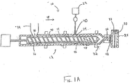
- an injection molding system 10 is used to produce an in-mold decorated article.
- An extruder 12 of molding system 10 includes a polymer processing screw 14 that is rotatable within a barrel 16 to convey polymeric material in a downstream direction 18 within a polymer processing space 20 defined between the screw and the barrel.
- a source 22 of blowing agent is connected to a blowing agent port 24 formed within the barrel to introduce blowing agent into the polymeric material, as described further below.
- Extruder 12 includes an outlet 26 of the extruder, for example a gate, connected to an injection mold 28 in which a substrate material 30 is positioned.
- injection molding system 10 operates cyclically to produce a series of in-mold decorated articles.
- screw 14 is positioned at a downstream end 32 of barrel 16 as illustrated in Fig. 1A .
- Polymeric material typically in pelletized form, is fed into polymer processing space 20 from a hopper 34 through an orifice 36.
- Barrel 16 may be heated by one or more heating units 37.
- Screw 14 rotates to plasticate polymeric material and to convey the polymeric material in downstream direction 18.
- Blowing agent is introduced into the polymeric material from source 22 through blowing agent port 24 to form a mixture of blowing agent and polymeric material in processing space 20. The mixture is conveyed downstream by the rotating screw and accumulated in a region 38 within the barrel downstream of the screw.
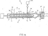
- the accumulation of the mixture in region 38 creates a pressure that forces the screw axially in an upstream direction in the barrel.
- screw 14 ceases to rotate and stops moving in the upstream direction ( Fig. 1B ).
- the flow of blowing agent into the polymeric material may be stopped, for example, by the operation of a shut-off valve 40 associated with the blowing agent port.
- the screw is moved axially in a downstream direction to downstream end 32 of the barrel ( Fig. 1C ) to inject the accumulated charge of the mixture through outlet 26 of the extruder and into a cavity 33 of mold 28.
- a valve 42 associated with the outlet of the extruder typically is opened to permit the mixture to flow into the mold.
- the injected mixture forces substrate 30 against a mold wall 44.
- the mixture of polymeric material and blowing agent is cooled in the mold, after which the mold is opened to produce an in-mold decorated article 60 ( Fig. 3 ) having a substrate formed integral with the molded polymeric portion.
- blowing agent introduction may be done through a plurality of blowing agent ports 24 arranged in the barrel, though it should be understood that a single port may also be utilized to form a single-phase solution.
- the ports can be arranged radially about the barrel or in a linear fashion along the axial length of the barrel. An arrangement of ports along the length of the barrel can facilitate injection of blowing agent at a relatively constant location relative to the screw when the screw moves axially (in an upstream direction) within the barrel as the mixture of polymeric material and blowing agent is accumulated.
- ports 24 may be placed at the 12:00 o'clock, 3:00 o'clock, 6:00 o'clock and 9:00 o'clock positions about the extruder barrel, or in any other configuration as desired.
- Blowing agent port 24 may include a single orifice or a plurality of orifices.
- the port may include at least about 2, and some cases at least about 4, and others at least about 10, and others at least about 40, and others at least about 100, and others at least about 300, and others at least about 500, and in still others at least about 700 blowing agent orifices.
- port 24 includes an orifice containing a porous material that permits blowing agent to flow therethrough and into the barrel, without the need to machine a plurality of individual orifices.
- blowing agent port 24 may be located at a blowing agent injection section 46 of the screw.
- the blowing agent injection section of the screw may include full, unbroken flight paths. In this manner, each flight, passes or “wipes" the blowing agent port including orifices periodically, when the screw is rotating. This wiping increases rapid mixing of blowing agent and polymeric material in the extruder and the result is a distribution of relatively finely divided, isolated regions of blowing agent in the polymeric material immediately upon injection into the barrel and prior to any mixing. This promotes formation of a uniform polymer and blowing agent mixture which may be desired in certain types of polymeric processing including microcellular processing.
- the screw Downstream of the blowing agent injection section, the screw may include a mixing section 48 which has highly broken flights to further mix the polymer and blowing agent mixture to promote formation of a single-phase solution.
- nucleation is achieved via a pressure drop, for example, that occurs when the solution passes through outlet 26 (e.g., a gate) which functions as a nucleating pathway.
- the nucleated sites in the solution grow into cells within the mold to form a polymeric foam material.
- the cell nucleation rate and growth may be controlled to form a microcellular polymeric material as described in International Publication No. WO 98/31521 (Pierick et. al.).
- nucleating pathways e. g. gates
- a high pressure drop rate for example greater than 0.1 GPa/s
- injection molding system 10 may be any suitable type known in the art. Examples of suitable injection molding systems, particularly when microcellular polymeric material are being produced, have been described, for example, in International Publication No. WO 98/31521 (Pierick et. al.) referenced above. Similarly, the in-mold decorating method of the present invention and the injection molding system 10 may have any number of variations known to one of ordinary skill in the art. For example, the methods and systems may utilize a separate accumulator external of the barrel to accumulate the mixture of polymeric material and blowing agent prior to injection into the mold. The methods and systems may also use a tandem extruder having a primary and secondary extruder.
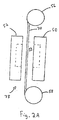
- substrate material 30 is provided as a continuous sheet .
- a first mold half 50 is separated from a second mold half 52 to provide a space 54 therebetween ( Fig. 2A ).
- a continuous sheet of substrate material 30 extends from a delivery roll 56 to a take-up roll 58 through space 54.
- Mold halves 50,52 are closed on peripheral portions of the continuous sheet so that substrate 30 is held across mold cavity 33 ( Fig. 2B ).
- a mixture of polymeric material and blowing agent is injected into mold cavity 33 and sufficiently cooled, after which mold halves 50,52 separate so that the article may be removed from the mold.
- Rolls 56,58 operate to provide a new portion of continuous sheet between the mold halves, and the process is repeated to produce additional in-mold decorated articles.
- substrate 30 may be provided according to any other technique known to one of ordinary skill in the art. For example, individual sheets of substrate material may be positioned within mold cavity 33 after each respective molding cycle. Also, substrate 30 may only extend across a portion of mold cavity 33 to provide in-mold decorated articles with substrate material covering selective regions of the article surface.
- injection pressure is defined as the pressure of the polymeric material entering the mold cavity.
- hydroaulic pressure is defined as the pressure of fluid (e. g., oil) used to provide the force that pushes the screw forward during the injection period of a molding cycle.
- injection temperature is defined as the melt temperature of the polymeric material entering the mold cavity.
- Conventional in-mold decorating processes generally require relatively high injection pressures (and hydraulic pressures) and temperatures to adequately fill the mold and, in some cases, to sufficiently impregnate the substrate to provide adequate adherence between the polymeric material and the substrate (e. g., between polymeric material and a fabric substrate).
- high injection pressures and injection temperatures may damage the substrate and can thus limit the types of substrates which are suitable.
- the present method advantageously expands the type of substrates that can be used as described further below.
- the injection pressure in the present method may be reduced by at least 0.69 MPa (100 psi) as compared to the injection pressure required for a polymeric material with no physical blowing agent under otherwise similar processing conditions. In some cases, the injection pressure is reduced by at least 1.38 MPa (200 psi), in other cases by at least 3.48 MPa (500 psi), and in still other cases by at least 6.90 MPa (1000 psi), as compared to polymeric material with no physical blowing agent under similar processing conditions.
- the injection pressure in the present method may be less than about 95% of the injection pressure, in other cases less than about 80% and in other cases less than about 70%, of the injection pressure required using a polymeric material with no physical blowing agent under otherwise similar processing conditions.
- the injection temperature may be reduced relative to the injection temperature required for a polymeric material with no physical blowing agent under otherwise similar processing conditions. In some cases, the injection temperature is reduced by at least 10 °C, in other cases by at least 30 °C, and in other cases by at least 50 °C as compared to polymeric material with no physical blowing agent under similar processing conditions.
- the physical blowing agent utilized in the method may have any suitable composition known in the art including nitrogen, carbon dioxide, hydrocarbons, chlorofluorocarbons, noble gases and the like, or mixtures thereof.
- the blowing agent may be introduced into the polymeric material in any flowable state, for example, a gas, liquid, or supercritical fluid.
- the blowing agent is in a supercritical state. That is, the blowing agent is a supercritical fluid under the temperature and pressure conditions within the extruder.
- Supercritical blowing agents are particularly effective at lowering the viscosity to a desired level for the methods of the present invention.
- the blowing agent is carbon dioxide.
- the blowing agent is nitrogen.
- the blowing agent is solely carbon dioxide or nitrogen. In preferred methods, carbon dioxide and nitrogen blowing agents are in the supercritical state within the extruder.
- Blowing agent may be introduced into the polymeric material to provide a mixture having the desired weight percentage for a particular process.
- the weight percentage of blowing agent may depend upon a number of variables including the selected viscosity reduction and the desired void fraction of the polymeric material in the in-mold decorated article. Generally, increasing the weight percentage of blowing agent in a mixture will further decrease the viscosity.
- the blowing agent percentage is typically less than about 15% by weight of the mixture of polymeric material and blowing agent. In some embodiments, the blowing agent level is less than about 8% and in some embodiments less than about 5%. In some cases, it may be preferable to use low weight percentages of blowing agent.
- the blowing agent level may be less than about 3%, in others less than about 1% and still others less than about 0.1% by weight of polymeric material and blowing agent mixture.
- the blowing agent weight percentage may also depend upon the type of blowing agent used. For example, to achieve the same reduction in viscosity, carbon dioxide typically has to be added at greater amounts than nitrogen.
- the blowing agent introduction rate may be coupled to the flow rate of polymeric material to produce a mixture having the desired weight percentage of blowing agent.
- Blowing agent may be introduced into the polymeric material over a wide range of flow rates.
- the blowing agent mass flow rate into the polymeric material may be between about 454 mg/hr (0.00 1 lbs/hr) and about 454 kg/hr (100 lbs/hr), in some cases between about 908 mg/hr (0.002 lbs/hr) and about 27.2 kg/hr (60 lbs/hr), and in some cases between about 9.08 g/hr (0.02 lbs/hr) and about 4.54 kg/hr (10 lbs/hr).
- Article 60 includes a polymeric material portion 62 and a substrate portion 64 adhered to a surface 66 of the polymeric material portion. As described above, substrate 64 is molded integral with the polymeric material portion and, thus, no external adhesive is required to adhere the portions together.
- In-mold decorated article 60 may be used in any number of applications including automotive, furniture, packaging, cosmetic, business equipment, and communication applications.
- Polymeric material portion 62 generally may comprise any type of polymeric material used in the art. Suitable materials include thermoplastic polymers which may be amorphous, semicrystalline, or crystalline materials. Typical examples of polymeric materials used to form portion 62 include styrenic polymers (e. g., polystyrene, ABS), polyolefins (e. g., polyethylene and polypropylene), fluoropolymers, polyamides, polyimides, polyesters, and the like.
- Substrate 64 generally may be any type of substrate used in the art to form in-mold decorated articles. Examples of substrates materials include fabrics, carpets, sheets, films such as plastic or metal films, and the like.
- the method of the present invention permits lower injection pressures and temperatures, a wider range of plastic material and substrate combinations may be utilized than with certain conventional in-mold decorating techniques.
- the high temperatures and pressures required to process certain polymeric materials cause damage to certain substrate materials (e. g., distortion or rupture).
- Relatively lower temperatures and pressures used in the methods of the present invention permit greater options for substrate materials selection.
- Polymeric substrate materials having a softening temperature similar to the softening temperature of the polymeric material portion may be utilized.
- the softening temperature of the substrate may be within than 20 °C of the softening temperature of the polymeric material, in some cases within than 10 °C of the softening temperature of the polymeric material, and in some cases substantially equal to the softening temperature of the polymeric material.
- softening temperature is defined as the melting temperature (T m ) for crystalline polymers and as the glass transition temperature (Tg) for amorphous plastics.
- in-mold decorated article 60 may include a substrate material 64 and a polymeric portion 62 each of which comprise the same polymeric component.
- the substrate material and the polymeric material may each be made of polypropylene.
- the substrate material may be made of acrylonitrile-butadiene-styrene (ABS) and the polymeric material may be made of polystyrene.
- Polymeric material portion 62 is a foam material which includes a plurality of cells formed within a polymer matrix.
- the blowing agent causes the nucleation and growth of the cells.
- plastic material portion 62 may be a solid plastic without any cells. In these cases, the blowing agent functions only as a viscosity lowering aid and does not nucleate and grow cells.
- the foam may have a wide range of void fractions.
- Polymeric foams may be used that have a void fraction of between about 1% and about 99%.
- higher density foams are used having a void fraction of less than 50%, in other cases a void fraction of less than 30%, and in some cases a void fraction of between about 5% and about 30%.
- the particular void fraction will depend upon the application.
- the plastic material portion is a microcellular material. Microcellular foams, or microcellular materials, have small cell sizes and high cell densities.
- the term "cell density" is defined as the number of cells per cubic centimeter of original, unexpanded polymeric material.
- the microcellular materials have an average cell size of less than 100 microns; in other embodiments, an average cell size of less than 75 microns; in other embodiments, an average cell size of less than 50 microns; in other embodiments, an average cell size of less than 25 microns; and, in still other embodiments, an average cell size of less than 10 microns.
- the cell size may be uniform, though a minority amount of cells may have a considerably larger or smaller cells size.
- the microcellular materials have a cell density of greater than 10 6 cells/cm 3 , in others greater than 10 7 cells/cm 3 , in others greater than 10 8 cells/cm 3 , and in others greater than 10 9 cells/cm 3 .
- in-mold decorated article 60 includes a polymeric foam portion 62, wherein at least 70% of the total number of cells in the polymeric portion have a cell size of less than 150 microns. In some embodiments at least 80%, in other cases at least 90%, in other cases at least 95%, and in other cases at least 99% of the total number of cells have a cell size of less than 150 microns. In other embodiments, the foam portion may be provided in which at least 30% of the total number of cells have a cell size of less than 800 microns, more preferably less than 500 microns, and more preferably less than 200 microns.
- polymeric material portion 62 may be a foam having a nonuniform cell size.
- different regions of portion 62 may have cells of different size.
- edge regions of portion 62 may generally have a smaller cell size than interior regions of portion 62.
- Polymeric material portion 62 is processed using a physical blowing agent and, thus, is generally free of residual chemical blowing agents or reaction byproducts of chemical blowing agents.
- the polymeric material may include a nucleating agent, such as talc or calcium carbonate.
- polymeric material portion 62 may be free of a nucleating agent.
- Polymeric material portion 62 may also include any number of other additives known in the art such as lubricants, plasticizers, colorants, fillers and the like.
- Polymeric material portion 62 may be formed over a wide variety of thicknesses depending upon the particular application. In some cases not according to the present invention, the thickness may be less than 0.5 inches. In other cases, relatively thin polymeric material portions are produced having a thickness of less than 2.5 mm (0.1 inches). The reduction of viscosity of polymeric material via the addition of the blowing agent permits formation of thin polymeric material portion and polymeric portions having large length-to-thickness ratios (1/t). As used herein, "1/t ratio" is defined as the ratio of the length of extension of a section of polymeric portion extending away from an injection location (gate) in the mold and the average thickness across that length. In some cases, polymeric material portion has an 1/t ratio of greater than 50: 1, in other cases greater than 100: 1, and in still other cases greater than 200: 1.
- Substrate portion 64 may be any of the type used in the art and is selected for the particular application of the in-mold decorated article.
- Substrate portion 64 may include decorative features such as a design, print, or other indicia. In some cases, the decorative features are formed using ink which is applied to the substrate surface. In other cases, the decorative features are created during the molding process.
- Substrate portion 64 may be colored, clear, shiny, and the like. When the substrate is a fabric, it may have any fabric pattern known in the art.
- substrate portion 64 may include only a single layer even when the substrate is a fabric material.
- no additional layer e. g., a separate barrier layer or a backing layer
- Conventional techniques generally employ a barrier layer, such as a finely knit textile or plastic layer, which prevents polymer from bleeding through under typical injection conditions. Because low pressures may be utilized in the present method, as described above, such barrier layers are not required.
- Substrate portion 64 is thin, even when fabric substrates are utilized and has a thickness of less than 254 ⁇ m (0.01 inches).
- Example 1 Production of In-Mold Decorated Article Including Polymeric Portion and Fabric Substrate
- An injection molding machine (Engel-500 ton) was modified to have a configuration similar to the system illustrated in Figs. 1A-1C .
- a two cavity pillar mold was used.
- the mold contained 3 gates per cavity and a hot runner system with 9 control zones.
- a fabric including a suede layer with a non-woven cotton backing was placed within each mold cavity.
- the suede layer had a thickness of about 21.6 mm (0.850 inches) and the backing had a thickness of about 4.05 mm (0.160 inches) to give a total fabric thickness of about 6.2 mm (0.245 inches).
- Polymeric pellets having a PC/ABS composition (GE Plastics Cycoloy MC 2231) were fed into the molding machine using the hopper. Trials were run using a variety of different blowing agent conditions, gate configurations, injection speeds, barrel temperatures, and hydraulic pressures. The conditions were summarized in Table 1.
- Table 1 Processing conditions Blowing Agent (Type-Wt.
- In-mold decorated automotive pillars having a polymeric ABS/PC portion adhered to the fabric substrate were produced.
- the pillars had a curved cross-section, a length of about 61 cm (24 inches), and a thickness of about 2.5 mm (0.10 inches).
- blowing agent reduced the hydraulic pressures and barrel temperatures which were used to produce the in-mold decorated articles.
- the reduction in hydraulic pressure was indicative of a reduction in injection pressure and the reduction in barrel temperature was indicative of a reduction in injection temperature.
- the reduction in hydraulic pressure was achieved even while increasing the injection speed, which at a fixed blowing agent percentage, would otherwise be expected to increase hydraulic pressure.
- This example illustrates the effectiveness of the method of the invention for producing an in-mold decorated article at low injection pressures and temperatures.
- Example 2 Production of In-Mold Decorated Article Including Polymeric Material and Fabric Substrate Without A Barrier Layer
- An injection molding machine (Milacron-400 ton) was modified to have a configuration similar to the system illustrated in Figs. 1A-1C .
- a pillar mold was used.
- the mold contained 3 gates and a hot runner system with 6 control zones. Only 1 gate was utilized in the experimentation.
- In-mold decorated automotive pillars having a polymeric PP portion adhered to the fabric substrate were produced using blowing agent (N 2 ). No polymeric material bled through the fabric when blowing agent was used.
- the pillars had a curved crosssection, a length of about 76 cm (30 inches), and a thickness of about 5 mm (0.20 inches).
- the pillars produced using blowing agent (N 2 ) had a void fraction of about 0.14.
- the polymeric portion of the in-mold decorated pillars produced using blowing agent (N 2 ) was a microcellular material having an average cell size of about 50 microns.
- Fig. 4 is an SEM photo showing the microstructure of a typical cross-section of the microcellular material of the in-mold decorated article.
- blowing agent reduced the hydraulic pressure and barrel temperature which were used to produce the in-mold decorated articles.
- the reduction in hydraulic pressure was indicative of a reduction in injection pressure and the reduction in barrel temperature was indicative of a reduction in injection temperature.
- This example illustrates the effectiveness of the method of the invention for producing an in-mold decorated article including a single fabric substrate without a barrier layer due to reductions in injection pressure and temperature. Furthermore, this example illustrates the production of an in-mold decorated article including a microcellular polymeric portion.
Landscapes
- Injection Moulding Of Plastics Or The Like (AREA)
- Manufacture Of Porous Articles, And Recovery And Treatment Of Waste Products (AREA)
- Laminated Bodies (AREA)
Description
- The present invention relates generally to injection molding of polymeric materials and, more particularly, to methods for producing in-mold decorated articles. The features of the pre-characterizing part of
claim 1 are disclosed inDE-A1-2341060 . - Polymeric materials may be processed to form articles having a number of different shapes and sizes. Conventional polymer processing techniques include injection molding, extrusion, and blow molding. Injection molding generally involves injecting molten plastic into a mold cavity, cooling the molten plastic, and opening the mold to produce an injected molded article having a shape similar to the mold cavity.
- In some cases, it may be desirable to adhere a substrate material to an exterior surface of a polymeric article. Such substrates may be used to enhance the appearance of the article and/or to improve properties (e. g., stiffness) of the article. Exemplary substrate materials include films and fabrics.
- In-mold decorating techniques produce molded articles which include a substrate adhered to a surface of the article. These techniques typically involve placing a substrate within the mold cavity so that molten polymer injected into the mold forces the substrate material against a mold wall. When the polymer cools, it adheres to the substrate material. The mold may be opened to produce a molded article having a substrate on its exterior surface. For examples, see
GB-A-1157616 US-A-3555130 . - Conventional in-mold decorating techniques typically involve injecting molten polymer at high temperatures and pressures into the mold to ensure adequate filling and/or sufficient adherence of the substrate to the plastic molded article. However, these conditions may damage certain types of substrates. For example, film substrates may shrink or crack as a result of high temperatures. Furthermore, when fabric substrates are used, a barrier layer may be required to prevent polymer from bleeding through the fabric as a result of high injection pressures. The barrier layer may add to the cost of producing the injection molded article and may reduce the adherence of the fabric to the polymeric material.
- Accordingly, there is a need for improved in-mold decorated articles and a method to produce the articles.
-
WO98/31521 WO99/04968 - The invention is defined in
claim 1 below. The dependent claims are directed to preferred embodiments. -
US-A-5997781 discloses a process for the production of an injection-expansion molded thermoplastic resin product. - Disclosed are in-mold decorated articles and methods to form the articles. The in-mold decorated articles include a thermoplastic polymeric portion having a substrate material adhered to a surface of the polymeric portion. The substrate material may be, for example, a film or a fabric. The polymeric portion may be, particularly, a microcellular polymeric material. The articles are formed by injecting a mixture of blowing agent and polymeric material into a mold cavity in which the substrate material is disposed, so that the substrate material is forced against a wall of the mold cavity. The blowing agent, which in certain preferred cases is a supercritical fluid, decreases the viscosity of the polymeric material and, therefore, enables reductions in injection pressures and temperatures. Reduced injection temperature and pressure may widen the processing window, increase flexibility in the selection of substrate materials, and can eliminate the need for a barrier layer that is sometimes used in conventional processes. The method may be used to produce a variety of in-mold decorated articles.
- An in-mold decorated article of injection-molded thermoplastic polymeric foam material wherein at least 70% of the total number of cells have a cell size of less than 150 microns, and a substrate adhered to a surface of the polymeric foam material can be provided.
- The method can be used to make an article which includes an injection-molded thermoplastic polymeric material having a softening temperature, and a substrate adhered to a surface of the injection molded polymeric material. The substrate includes a polymer having a softening temperature within 20 C of the softening temperature of the injection molded polymeric material.
- The invention provides a method for forming an in-mold decorated article. The method includes molding a fluid thermoplastic polymeric material against a substrate, and allowing the fluid polymeric material to harden and adhere to the substrate as a microcellular polymeric material having an average cell size of less than 100 microns.
- The method can include introducing a physical blowing agent into polymeric material in a polymer processing apparatus. The method further can include mixing the blowing agent and the polymeric material under conditions at which the blowing agent is a supercritical fluid, and injecting a mixture of polymeric material and blowing agent into the mold cavity.
- The method can make use of a polymer molding system including an extruder, a mold, and a substrate disposed within a cavity of the mold. The system is constructed and arranged to deliver blowing-agent-free molten polymeric material from the extruder into the mold cavity at a minimum injection pressure and to solidify the polymeric material in the mold to form an in-mold decorated article having the substrate adhered to a surface of a polymeric material portion. The method can further include delivering polymeric material admixed with a blowing agent from the extruder into the mold cavity, at an injection pressure of less than 95% of the minimum injection pressure, and solidifying the polymeric material in the mold to form an in-mold decorated article having the substrate adhered to a surface of a polymeric material portion.
- Other advantages, aspects, and features will become apparent from the following detailed description when considered in conjunction with the accompanying drawings.
-
-
Fig. 1A schematically illustrates an injection molding system at the beginning of a molding cycle used to produce in-mold decorated articles. -
Fig. 1B schematically illustrates the injection molding system ofFig. 1A after a charge of polymeric material and blowing agent has been accumulated. -
Fig. 1C schematically illustrates the injection molding system ofFig. 1A after the charge of polymeric material and blowing agent has been injected into the mold to form the in-mold decorated article. -
Fig. 2A and2B schematically illustrate an injection mold and an assembly for providing a continuous sheet of substrate material to the mold when the mold is open and when the mold is closed, respectively. -
Fig. 3 schematically illustrates an in-mold decorated article. -
Fig. 4 is an SEM photo of the microstructure of the polymeric material portion of the in-mold decorated article produced in Example 1. - There is provided an in-molded decorated article and a method for producing the article. The method includes introducing a blowing agent into polymeric material in a polymer processing apparatus to form a mixture of blowing agent and polymeric material having a reduced viscosity relative to the polymeric material. The mixture is injected into a mold cavity in which a substrate material is positioned. The substrate is forced against the mold wall and the mixture is cooled to form an in-mold decorated article having a substrate covering a polymeric portion of the article. As described further below, the polymeric portion of the article may be a polymeric foam and, in particular, a microcellular polymeric material.
- Referring to
Figs. 1A-1C , aninjection molding system 10 is used to produce an in-mold decorated article. Anextruder 12 ofmolding system 10 includes apolymer processing screw 14 that is rotatable within abarrel 16 to convey polymeric material in adownstream direction 18 within apolymer processing space 20 defined between the screw and the barrel. Asource 22 of blowing agent is connected to ablowing agent port 24 formed within the barrel to introduce blowing agent into the polymeric material, as described further below.Extruder 12 includes anoutlet 26 of the extruder, for example a gate, connected to aninjection mold 28 in which asubstrate material 30 is positioned. - Generally,
injection molding system 10 operates cyclically to produce a series of in-mold decorated articles. At the beginning of a typical molding cycle, screw 14 is positioned at adownstream end 32 ofbarrel 16 as illustrated inFig. 1A . Polymeric material, typically in pelletized form, is fed intopolymer processing space 20 from ahopper 34 through anorifice 36.Barrel 16 may be heated by one or more heating units 37.Screw 14 rotates to plasticate polymeric material and to convey the polymeric material indownstream direction 18. Blowing agent is introduced into the polymeric material fromsource 22 throughblowing agent port 24 to form a mixture of blowing agent and polymeric material inprocessing space 20. The mixture is conveyed downstream by the rotating screw and accumulated in aregion 38 within the barrel downstream of the screw. The accumulation of the mixture inregion 38 creates a pressure that forces the screw axially in an upstream direction in the barrel. After a sufficient charge of the mixture has been accumulated, screw 14 ceases to rotate and stops moving in the upstream direction (Fig. 1B ). Preferably, when the screw no longer plasticates polymeric material the flow of blowing agent into the polymeric material may be stopped, for example, by the operation of a shut-offvalve 40 associated with the blowing agent port. Then, the screw is moved axially in a downstream direction todownstream end 32 of the barrel (Fig. 1C ) to inject the accumulated charge of the mixture throughoutlet 26 of the extruder and into acavity 33 ofmold 28. Avalve 42 associated with the outlet of the extruder typically is opened to permit the mixture to flow into the mold. The injectedmixture forces substrate 30 against amold wall 44. The mixture of polymeric material and blowing agent is cooled in the mold, after which the mold is opened to produce an in-mold decorated article 60 (Fig. 3 ) having a substrate formed integral with the molded polymeric portion. - In some embodiments, it may be preferable to form a single-phase solution of polymeric material and blowing agent within
polymer processing space 20 and to maintain the single-phase condition until the solution is injected intomold 28, particularly when the polymeric portion of the in-mold decorated article is a microcellular material. - To aid in the formation of the single-phase solution, blowing agent introduction may be done through a plurality of blowing
agent ports 24 arranged in the barrel, though it should be understood that a single port may also be utilized to form a single-phase solution. Whenmultiple ports 24 are utilized, the ports can be arranged radially about the barrel or in a linear fashion along the axial length of the barrel. An arrangement of ports along the length of the barrel can facilitate injection of blowing agent at a relatively constant location relative to the screw when the screw moves axially (in an upstream direction) within the barrel as the mixture of polymeric material and blowing agent is accumulated. Where radially-arranged ports are used,ports 24 may be placed at the 12:00 o'clock, 3:00 o'clock, 6:00 o'clock and 9:00 o'clock positions about the extruder barrel, or in any other configuration as desired.Blowing agent port 24 may include a single orifice or a plurality of orifices. In the multi-orifice embodiments (not illustrated), the port may include at least about 2, and some cases at least about 4, and others at least about 10, and others at least about 40, and others at least about 100, and others at least about 300, and others at least about 500, and in still others at least about 700 blowing agent orifices. In another embodiment,port 24 includes an orifice containing a porous material that permits blowing agent to flow therethrough and into the barrel, without the need to machine a plurality of individual orifices. - To further promote the formation of a single-phase solution, blowing
agent port 24 may be located at a blowingagent injection section 46 of the screw. The blowing agent injection section of the screw may include full, unbroken flight paths. In this manner, each flight, passes or "wipes" the blowing agent port including orifices periodically, when the screw is rotating. This wiping increases rapid mixing of blowing agent and polymeric material in the extruder and the result is a distribution of relatively finely divided, isolated regions of blowing agent in the polymeric material immediately upon injection into the barrel and prior to any mixing. This promotes formation of a uniform polymer and blowing agent mixture which may be desired in certain types of polymeric processing including microcellular processing. Downstream of the blowing agent injection section, the screw may include amixing section 48 which has highly broken flights to further mix the polymer and blowing agent mixture to promote formation of a single-phase solution. - In some embodiments in which a single-phase solution of polymeric material and blowing agent is formed, it may be preferable to nucleate the solution when injecting into
mold 28. Nucleation is achieved via a pressure drop, for example, that occurs when the solution passes through outlet 26 (e.g., a gate) which functions as a nucleating pathway. The nucleated sites in the solution grow into cells within the mold to form a polymeric foam material. In some cases, the cell nucleation rate and growth may be controlled to form a microcellular polymeric material as described in International Publication No.WO 98/31521 - It should be understood that
injection molding system 10 may be any suitable type known in the art. Examples of suitable injection molding systems, particularly when microcellular polymeric material are being produced, have been described, for example, in International Publication No.WO 98/31521 injection molding system 10 may have any number of variations known to one of ordinary skill in the art. For example, the methods and systems may utilize a separate accumulator external of the barrel to accumulate the mixture of polymeric material and blowing agent prior to injection into the mold. The methods and systems may also use a tandem extruder having a primary and secondary extruder. - Referring to
Figs. 2A-2B ,substrate material 30 is provided as a continuous sheet . At the beginning of a mold cycle, afirst mold half 50 is separated from asecond mold half 52 to provide aspace 54 therebetween (Fig. 2A ). A continuous sheet ofsubstrate material 30 extends from adelivery roll 56 to a take-up roll 58 throughspace 54. Mold halves 50,52 are closed on peripheral portions of the continuous sheet so thatsubstrate 30 is held across mold cavity 33 (Fig. 2B ). As described above, a mixture of polymeric material and blowing agent is injected intomold cavity 33 and sufficiently cooled, after which mold halves 50,52 separate so that the article may be removed from the mold.Rolls - It should be understood that
substrate 30 may be provided according to any other technique known to one of ordinary skill in the art. For example, individual sheets of substrate material may be positioned withinmold cavity 33 after each respective molding cycle. Also,substrate 30 may only extend across a portion ofmold cavity 33 to provide in-mold decorated articles with substrate material covering selective regions of the article surface. - The introduction of a physical blowing agent into the polymeric material in the method of the present invention reduces the viscosity of the polymeric material. The reduction in viscosity improves the flow of the mixture into the mold which can allow a decorated article to be molded at relatively low injection temperatures and pressures. As used herein, "injection pressure" is defined as the pressure of the polymeric material entering the mold cavity. The injection pressure is also related to the "hydraulic pressure" which, as used herein, is defined as the pressure of fluid (e. g., oil) used to provide the force that pushes the screw forward during the injection period of a molding cycle. Thus, the method of the invention also provides a reduction in hydraulic pressure. As used herein, "injection temperature" is defined as the melt temperature of the polymeric material entering the mold cavity. Conventional in-mold decorating processes generally require relatively high injection pressures (and hydraulic pressures) and temperatures to adequately fill the mold and, in some cases, to sufficiently impregnate the substrate to provide adequate adherence between the polymeric material and the substrate (e. g., between polymeric material and a fabric substrate). However, high injection pressures and injection temperatures may damage the substrate and can thus limit the types of substrates which are suitable. By lowering the injection temperature and pressure required, the present method advantageously expands the type of substrates that can be used as described further below.
- In some cases, the injection pressure in the present method may be reduced by at least 0.69 MPa (100 psi) as compared to the injection pressure required for a polymeric material with no physical blowing agent under otherwise similar processing conditions. In some cases, the injection pressure is reduced by at least 1.38 MPa (200 psi), in other cases by at least 3.48 MPa (500 psi), and in still other cases by at least 6.90 MPa (1000 psi), as compared to polymeric material with no physical blowing agent under similar processing conditions. In some cases, the injection pressure in the present method may be less than about 95% of the injection pressure, in other cases less than about 80% and in other cases less than about 70%, of the injection pressure required using a polymeric material with no physical blowing agent under otherwise similar processing conditions. Similarly, the injection temperature may be reduced relative to the injection temperature required for a polymeric material with no physical blowing agent under otherwise similar processing conditions. In some cases, the injection temperature is reduced by at least 10 °C, in other cases by at least 30 °C, and in other cases by at least 50 °C as compared to polymeric material with no physical blowing agent under similar processing conditions.
- The physical blowing agent utilized in the method may have any suitable composition known in the art including nitrogen, carbon dioxide, hydrocarbons, chlorofluorocarbons, noble gases and the like, or mixtures thereof. The blowing agent may be introduced into the polymeric material in any flowable state, for example, a gas, liquid, or supercritical fluid. Preferably, once introduced into the polymeric material in the extruder, the blowing agent is in a supercritical state. That is, the blowing agent is a supercritical fluid under the temperature and pressure conditions within the extruder. Supercritical blowing agents are particularly effective at lowering the viscosity to a desired level for the methods of the present invention. According to one preferred embodiment, the blowing agent is carbon dioxide. In another preferred embodiment the blowing agent is nitrogen. In certain embodiments, the blowing agent is solely carbon dioxide or nitrogen. In preferred methods, carbon dioxide and nitrogen blowing agents are in the supercritical state within the extruder.
- Blowing agent may be introduced into the polymeric material to provide a mixture having the desired weight percentage for a particular process. The weight percentage of blowing agent may depend upon a number of variables including the selected viscosity reduction and the desired void fraction of the polymeric material in the in-mold decorated article. Generally, increasing the weight percentage of blowing agent in a mixture will further decrease the viscosity. The blowing agent percentage is typically less than about 15% by weight of the mixture of polymeric material and blowing agent. In some embodiments, the blowing agent level is less than about 8% and in some embodiments less than about 5%. In some cases, it may be preferable to use low weight percentages of blowing agent. For example, the blowing agent level may be less than about 3%, in others less than about 1% and still others less than about 0.1% by weight of polymeric material and blowing agent mixture. The blowing agent weight percentage may also depend upon the type of blowing agent used. For example, to achieve the same reduction in viscosity, carbon dioxide typically has to be added at greater amounts than nitrogen.
- The blowing agent introduction rate may be coupled to the flow rate of polymeric material to produce a mixture having the desired weight percentage of blowing agent. Blowing agent may be introduced into the polymeric material over a wide range of flow rates. In some embodiments, the blowing agent mass flow rate into the polymeric material may be between about 454 mg/hr (0.00 1 lbs/hr) and about 454 kg/hr (100 lbs/hr), in some cases between about 908 mg/hr (0.002 lbs/hr) and about 27.2 kg/hr (60 lbs/hr), and in some cases between about 9.08 g/hr (0.02 lbs/hr) and about 4.54 kg/hr (10 lbs/hr).
- Referring to
Fig. 3 , an in-mold decoratedarticle 60 is schematically illustrated.Article 60 includes apolymeric material portion 62 and asubstrate portion 64 adhered to asurface 66 of the polymeric material portion. As described above,substrate 64 is molded integral with the polymeric material portion and, thus, no external adhesive is required to adhere the portions together. In-mold decoratedarticle 60 may be used in any number of applications including automotive, furniture, packaging, cosmetic, business equipment, and communication applications. -
Polymeric material portion 62 generally may comprise any type of polymeric material used in the art. Suitable materials include thermoplastic polymers which may be amorphous, semicrystalline, or crystalline materials. Typical examples of polymeric materials used to formportion 62 include styrenic polymers (e. g., polystyrene, ABS), polyolefins (e. g., polyethylene and polypropylene), fluoropolymers, polyamides, polyimides, polyesters, and the like.Substrate 64 generally may be any type of substrate used in the art to form in-mold decorated articles. Examples of substrates materials include fabrics, carpets, sheets, films such as plastic or metal films, and the like. - Because the method of the present invention permits lower injection pressures and temperatures, a wider range of plastic material and substrate combinations may be utilized than with certain conventional in-mold decorating techniques. For example using certain conventional techniques, the high temperatures and pressures required to process certain polymeric materials cause damage to certain substrate materials (e. g., distortion or rupture). Relatively lower temperatures and pressures used in the methods of the present invention permit greater options for substrate materials selection. Polymeric substrate materials having a softening temperature similar to the softening temperature of the polymeric material portion may be utilized. For example, the softening temperature of the substrate may be within than 20 °C of the softening temperature of the polymeric material, in some cases within than 10 °C of the softening temperature of the polymeric material, and in some cases substantially equal to the softening temperature of the polymeric material. As used herein, "softening temperature" is defined as the melting temperature (Tm) for crystalline polymers and as the glass transition temperature (Tg) for amorphous plastics. In some embodiments, in-mold decorated
article 60 may include asubstrate material 64 and apolymeric portion 62 each of which comprise the same polymeric component. For example, the substrate material and the polymeric material may each be made of polypropylene. Also, the substrate material may be made of acrylonitrile-butadiene-styrene (ABS) and the polymeric material may be made of polystyrene. -
Polymeric material portion 62 is a foam material which includes a plurality of cells formed within a polymer matrix. In these cases, the blowing agent causes the nucleation and growth of the cells. However, in other cases not according to the present invention,plastic material portion 62 may be a solid plastic without any cells. In these cases, the blowing agent functions only as a viscosity lowering aid and does not nucleate and grow cells. - In embodiments in which the polymeric material portion is a foam material, the foam may have a wide range of void fractions. Polymeric foams may be used that have a void fraction of between about 1% and about 99%. In some embodiments, higher density foams are used having a void fraction of less than 50%, in other cases a void fraction of less than 30%, and in some cases a void fraction of between about 5% and about 30%. The particular void fraction will depend upon the application. In the embodiments according to the invention, the plastic material portion is a microcellular material. Microcellular foams, or microcellular materials, have small cell sizes and high cell densities. As used herein, the term "cell density" is defined as the number of cells per cubic centimeter of original, unexpanded polymeric material. In some embodiments, the microcellular materials have an average cell size of less than 100 microns; in other embodiments, an average cell size of less than 75 microns; in other embodiments, an average cell size of less than 50 microns; in other embodiments, an average cell size of less than 25 microns; and, in still other embodiments, an average cell size of less than 10 microns. In some of these microcellular embodiments, the cell size may be uniform, though a minority amount of cells may have a considerably larger or smaller cells size. In some cases, the microcellular materials have a cell density of greater than 106 cells/cm3, in others greater than 107 cells/cm3, in others greater than 108 cells/cm3, and in others greater than 109 cells/cm3.
- In another set of embodiments, in-mold decorated
article 60 includes apolymeric foam portion 62, wherein at least 70% of the total number of cells in the polymeric portion have a cell size of less than 150 microns. In some embodiments at least 80%, in other cases at least 90%, in other cases at least 95%, and in other cases at least 99% of the total number of cells have a cell size of less than 150 microns. In other embodiments, the foam portion may be provided in which at least 30% of the total number of cells have a cell size of less than 800 microns, more preferably less than 500 microns, and more preferably less than 200 microns. - In certain cases,
polymeric material portion 62 may be a foam having a nonuniform cell size. In some of these cases, different regions ofportion 62 may have cells of different size. For example, edge regions ofportion 62 may generally have a smaller cell size than interior regions ofportion 62. -
Polymeric material portion 62, as described above, is processed using a physical blowing agent and, thus, is generally free of residual chemical blowing agents or reaction byproducts of chemical blowing agents. Optionally, the polymeric material may include a nucleating agent, such as talc or calcium carbonate. In other embodiments,polymeric material portion 62 may be free of a nucleating agent.Polymeric material portion 62 may also include any number of other additives known in the art such as lubricants, plasticizers, colorants, fillers and the like. -
Polymeric material portion 62 may be formed over a wide variety of thicknesses depending upon the particular application. In some cases not according to the present invention, the thickness may be less than 0.5 inches. In other cases, relatively thin polymeric material portions are produced having a thickness of less than 2.5 mm (0.1 inches). The reduction of viscosity of polymeric material via the addition of the blowing agent permits formation of thin polymeric material portion and polymeric portions having large length-to-thickness ratios (1/t). As used herein, "1/t ratio" is defined as the ratio of the length of extension of a section of polymeric portion extending away from an injection location (gate) in the mold and the average thickness across that length. In some cases, polymeric material portion has an 1/t ratio of greater than 50: 1, in other cases greater than 100: 1, and in still other cases greater than 200: 1. -
Substrate portion 64 may be any of the type used in the art and is selected for the particular application of the in-mold decorated article.Substrate portion 64 may include decorative features such as a design, print, or other indicia. In some cases, the decorative features are formed using ink which is applied to the substrate surface. In other cases, the decorative features are created during the molding process.Substrate portion 64 may be colored, clear, shiny, and the like. When the substrate is a fabric, it may have any fabric pattern known in the art. - When desired,
substrate portion 64 may include only a single layer even when the substrate is a fabric material. In these embodiments, no additional layer (e. g., a separate barrier layer or a backing layer) separates thefabric substrate portion 64 frompolymeric material portion 62. Conventional techniques generally employ a barrier layer, such as a finely knit textile or plastic layer, which prevents polymer from bleeding through under typical injection conditions. Because low pressures may be utilized in the present method, as described above, such barrier layers are not required.Substrate portion 64 is thin, even when fabric substrates are utilized and has a thickness of less than 254 µm (0.01 inches). - The function and advantages of these and other embodiments will be more fully understood from the examples below. The following examples are intended to illustrate the benefits but do not exemplify the full scope .
- An injection molding machine (Engel-500 ton) was modified to have a configuration similar to the system illustrated in
Figs. 1A-1C . A two cavity pillar mold was used. The mold contained 3 gates per cavity and a hot runner system with 9 control zones. - A fabric including a suede layer with a non-woven cotton backing was placed within each mold cavity. The suede layer had a thickness of about 21.6 mm (0.850 inches) and the backing had a thickness of about 4.05 mm (0.160 inches) to give a total fabric thickness of about 6.2 mm (0.245 inches). Polymeric pellets having a PC/ABS composition (GE Plastics Cycoloy MC 2231) were fed into the molding machine using the hopper. Trials were run using a variety of different blowing agent conditions, gate configurations, injection speeds, barrel temperatures, and hydraulic pressures. The conditions were summarized in Table 1.
Table 1: Processing conditions Blowing Agent (Type-Wt. %) # of Gates Injection Speed (inch/sec) Barrel Temperature (°C) Hydraulic Pressure MPa (psi) Solid - 0% 3 2 271 16.00 (2320) Solid - 0% 3 0.5 271 15.13 (2194) N2 - 0.5% 3 0.8 249 15.80 (2291) CO2 - 2% 3 0.7 249 12.03 (1745) CO2 - 3.4% 3 0.7 249 11.70 (1697) CO2 - 3.7% 3 1.0 249 10.03 (1455) CO2 - 3.1% 1 1.8 249 15.20 (2205) - In-mold decorated automotive pillars having a polymeric ABS/PC portion adhered to the fabric substrate were produced. The pillars had a curved cross-section, a length of about 61 cm (24 inches), and a thickness of about 2.5 mm (0.10 inches). The in-mold decorated articles produced using blowing agent (CO2 and N2), had a void fraction of between about 0.05 and 0.14.
- The use of blowing agent reduced the hydraulic pressures and barrel temperatures which were used to produce the in-mold decorated articles. The reduction in hydraulic pressure was indicative of a reduction in injection pressure and the reduction in barrel temperature was indicative of a reduction in injection temperature. The reduction in hydraulic pressure was achieved even while increasing the injection speed, which at a fixed blowing agent percentage, would otherwise be expected to increase hydraulic pressure.
- This example illustrates the effectiveness of the method of the invention for producing an in-mold decorated article at low injection pressures and temperatures.
- An injection molding machine (Milacron-400 ton) was modified to have a configuration similar to the system illustrated in
Figs. 1A-1C . A pillar mold was used. The mold contained 3 gates and a hot runner system with 6 control zones. Only 1 gate was utilized in the experimentation. - A single layer polypropylene fabric with no backing or separate barrier layer was placed within the mold cavity. The fabric had a thickness of about 254µm (0.010 inches). Polymeric pellets having a PP composition which included 20% talc by weight (Mitsui Plastics TS0P5, 30 MFR) were fed into the molding machine using the hopper. Trials were run using different blowing agent conditions, barrel temperatures, and hydraulic pressures. The conditions were summarized in Table 2.
Table 2: Process Conditions Blowing Agent (Type-Wt. %) Barrel Temperature (°C) Injection Speed mm/sec (inch/sec) Hydraulic Pressure MPa (psi) Solid - 0% 204 25.4 (1.0) 10.69 (1550) N2 - 0.5% 193 25.4 (1.0) 9.79 (1420) - When no blowing agent was used, polymeric material bled through the fabric substrate. Thus, the in-mold decorated article produced without blowing agent was unacceptable.
- In-mold decorated automotive pillars having a polymeric PP portion adhered to the fabric substrate were produced using blowing agent (N2). No polymeric material bled through the fabric when blowing agent was used. The pillars had a curved crosssection, a length of about 76 cm (30 inches), and a thickness of about 5 mm (0.20 inches). The pillars produced using blowing agent (N2) had a void fraction of about 0.14. The polymeric portion of the in-mold decorated pillars produced using blowing agent (N2) was a microcellular material having an average cell size of about 50 microns.
Fig. 4 is an SEM photo showing the microstructure of a typical cross-section of the microcellular material of the in-mold decorated article. - The use of blowing agent reduced the hydraulic pressure and barrel temperature which were used to produce the in-mold decorated articles. The reduction in hydraulic pressure was indicative of a reduction in injection pressure and the reduction in barrel temperature was indicative of a reduction in injection temperature.
- This example illustrates the effectiveness of the method of the invention for producing an in-mold decorated article including a single fabric substrate without a barrier layer due to reductions in injection pressure and temperature. Furthermore, this example illustrates the production of an in-mold decorated article including a microcellular polymeric portion.
- Those skilled in the art would readily appreciate that all parameters listed herein are meant to be exemplary and that the actual parameters would depend upon the specific application for which the methods and articles of the invention are used. It is, therefore, to be understood that the foregoing embodiments are presented by way of example only and that, within the scope of the appended claims, the invention may be practiced otherwise than as specifically described.
Claims (11)
- A method for forming an in-mold decorated article in a mold cavity (33), the method comprising:placing in the mold cavity a sheet substrate (30), the substrate having a thickness of less than 254 µm (0.01 inch);molding a fluid thermoplastic polymeric material against the substrate;allowing the fluid polymeric material to harden and adhere to the substrate; andopening the mold to release a molded article (60) with an exterior surface decorated with said substrate; andcharacterized by the further steps of:introducing a physical blowing agent into the polymeric material to form the mixture of polymeric material and blowing agent; andinjecting the mixture of polymeric material and blowing agent into the mold cavity, whereby the material hardens as a microcellular polymeric material having an average cell size of less than 100 microns and having a thickness of less than 2.54 mm (0.1 inch).
- The method of claim 1, comprising mixing the blowing agent and the polymeric material under conditions at which the blowing agent is a supercritical fluid.
- The method of claim 1 or 2, wherein the blowing agent comprises carbon dioxide.
- The method of claim 1 or 2, wherein the blowing agent comprises nitrogen.
- The method of any one of the preceding claims, comprising injecting a single-phase solution of polymeric material and blowing agent into the mold cavity.
- The method of any one of the preceding claims, wherein the substrate material has a single layer.
- The method of any one of the preceding claims, wherein the substrate comprises a fabric material.
- The method of any one of claims 1 to 6, wherein the substrate comprises a plastic film.
- The method of any one of the preceding claims, wherein the polymeric material comprises polypropylene and the substrate comprises polypropylene.
- The method of any one of claims 1 to 8, wherein the polymeric material comprises acrylonitrile-butadiene-styrene and the substrate comprises polystyrene.
- The method of any one of the preceding claims, wherein the microcellular polymeric material has an average cell size of less than 50 microns.
Applications Claiming Priority (3)
| Application Number | Priority Date | Filing Date | Title |
|---|---|---|---|
| US67625100A | 2000-09-29 | 2000-09-29 | |
| US676251 | 2000-09-29 | ||
| PCT/US2001/042396 WO2002026484A1 (en) | 2000-09-29 | 2001-10-01 | In-mold decorated articles and methods |
Publications (3)
| Publication Number | Publication Date |
|---|---|
| EP1320457A1 EP1320457A1 (en) | 2003-06-25 |
| EP1320457A4 EP1320457A4 (en) | 2008-12-17 |
| EP1320457B1 true EP1320457B1 (en) | 2016-04-20 |
Family
ID=24713775
Family Applications (1)
| Application Number | Title | Priority Date | Filing Date |
|---|---|---|---|
| EP01977858.8A Expired - Lifetime EP1320457B1 (en) | 2000-09-29 | 2001-10-01 | Method for forming in-mold decorated article |
Country Status (6)
| Country | Link |
|---|---|
| US (2) | US7364677B2 (en) |
| EP (1) | EP1320457B1 (en) |
| JP (1) | JP2004523375A (en) |
| KR (1) | KR20030034229A (en) |
| AU (1) | AU2001296942A1 (en) |
| WO (1) | WO2002026484A1 (en) |
Families Citing this family (15)
| Publication number | Priority date | Publication date | Assignee | Title |
|---|---|---|---|---|
| AU2001296942A1 (en) * | 2000-09-29 | 2002-04-08 | Trexel, Inc. | In-mold decorated articles and methods |
| US20080034666A1 (en) * | 2005-02-15 | 2008-02-14 | Jyawook Sam M | Thermoplastic vehicle weather stripping |
| ES2324754B1 (en) * | 2007-03-20 | 2010-05-26 | Bsh Electrodomesticos España, S.A. | PLASTIC ELECTRODOMESTIC DOOR HANDLE. |
| FR2930738B1 (en) * | 2008-04-30 | 2013-03-01 | Veriplast Decorative | PROCESS FOR MAKING AT LEAST ONE AREA IN RELIEF ON A CONTAINER OF PLASTIC MATERIAL |
| WO2010083534A1 (en) * | 2009-01-19 | 2010-07-22 | Avery Dennison Corporation | Durable in-mold decoration laminates using semi-crystalline polymer as top film |
| US20100198133A1 (en) * | 2009-02-05 | 2010-08-05 | Playtex Products, Inc. | Microcellular injection molding processes for personal and consumer care products and packaging |
| RU2012111834A (en) * | 2009-08-28 | 2013-10-10 | Клоужер Системз Интернэшнл, Инк. | METHOD FOR COMPRESSION FORMING PLASTIC CAMPS FROM FOAM POLYMER MATERIAL |
| US8563621B2 (en) | 2010-04-21 | 2013-10-22 | Polyfil Corporation | Blowing agents formed from nanoparticles of carbonates |
| US8696957B2 (en) * | 2010-09-10 | 2014-04-15 | Eveready Battery Company, Inc | Methods for microcellular injection molding |
| KR101536399B1 (en) * | 2013-05-03 | 2015-07-14 | 한국기계연구원 | In mold coating device |
| EP2871085B1 (en) * | 2013-11-07 | 2019-01-09 | Inalfa Roof Systems Group B.V. | Rollo assembly |
| DE102017206090A1 (en) * | 2017-04-10 | 2018-10-11 | Bayerische Motoren Werke Aktiengesellschaft | A method of making a foamed decorative article for a motor vehicle, film for use in such a process and foamed decoratable carrier |
| US11332593B2 (en) | 2018-03-01 | 2022-05-17 | Trexel, Inc. | Blowing agents in polymer foam processing systems |
| US20190291314A1 (en) * | 2018-03-20 | 2019-09-26 | Trexel, Inc. | Polymer foam processing including different types of blowing agent |
| CN117901339B (en) * | 2024-02-08 | 2026-04-21 | 景德镇陶瓷大学 | A method and product for manufacturing microporous foam injection molded articles with eggshell-like membrane structure composite microporous membrane surface decoration. |
Citations (6)
| Publication number | Priority date | Publication date | Assignee | Title |
|---|---|---|---|---|
| GB1157616A (en) * | 1965-08-13 | 1969-07-09 | Marley Tile Co Ltd | Polyurethane Foam Materials. |
| US3555130A (en) * | 1966-08-29 | 1971-01-12 | Davidson Rubber Co | Forming pigmented integrally bonded coverings on articles of microcellular urethane foam |
| DE2341060A1 (en) * | 1972-10-24 | 1975-02-27 | Basf Ag | Injection mouldings with improved surface characteristics - by inserting a laminated foil into the mould prior to moulding |
| JPS5973928A (en) * | 1982-10-20 | 1984-04-26 | Polyurethan Kasei Kk | Manufacture of scavenger in piping |
| US4661391A (en) * | 1984-03-02 | 1987-04-28 | Noel, Marquet & Cie. S.A. | Method of making a moulded body of foam plastics material |
| EP0825010A2 (en) * | 1996-08-20 | 1998-02-25 | Sumitomo Chemical Company, Limited | A fiber-reinforced article and a method for producing the same |
Family Cites Families (94)
| Publication number | Priority date | Publication date | Assignee | Title |
|---|---|---|---|---|
| US2005A (en) * | 1841-03-16 | Improvement in the manner of constructing molds for casting butt-hinges | ||
| US2008A (en) * | 1841-03-18 | Gas-lamp eok conducting gas pkom ah elevated buhner to one below it | ||
| US2007A (en) * | 1841-03-16 | Improvement in the mode of harvesting grain | ||
| US2009A (en) * | 1841-03-18 | Improvement in machines for boring war-rockets | ||
| US2002A (en) * | 1841-03-12 | Tor and planter for plowing | ||
| FR1255499A (en) * | 1960-01-28 | 1961-03-10 | Ets Kuhlmann | Lightweight material resistant to pressure and stress, its manufacture and applications |
| US3227664A (en) * | 1961-12-07 | 1966-01-04 | Du Pont | Ultramicrocellular structures of crystalline organic polymer |
| US3384531A (en) * | 1961-12-07 | 1968-05-21 | Du Pont | Flattened ultra-microcellular structure and method for making same |
| US3251911A (en) * | 1963-04-16 | 1966-05-17 | Bell Telephone Labor Inc | Preparation of expanded polymers |
| GB1062086A (en) * | 1963-08-16 | 1967-03-15 | Du Pont | Improvements in or relating to ultramicrocellular structures |
| US3375211A (en) * | 1963-08-16 | 1968-03-26 | Du Pont | Ultramicrocellular polymeric structures containing an inflatant |
| GB1050197A (en) * | 1963-11-27 | |||
| US3436446A (en) * | 1966-06-08 | 1969-04-01 | Union Carbide Corp | Molding of foamed thermoplastic articles |
| US3812225A (en) * | 1967-01-23 | 1974-05-21 | Furukawa Electric Co Ltd | Method of manufacturing foamed crosslinked polyolefin slabs involving multiple expansion techniques and direct gas pressure |
| US3375212A (en) * | 1967-02-14 | 1968-03-26 | Du Pont | Microcellular polymeric structure |
| US3787543A (en) * | 1968-12-27 | 1974-01-22 | Du Pont | Process for the preparation of low density microcellular foam sheets exhibiting high work-to-tear values |
| US3637458A (en) * | 1968-12-27 | 1972-01-25 | Du Pont | Microcellular foam sheet |
| US3697204A (en) * | 1970-05-07 | 1972-10-10 | Usm Corp | Apparatus for injection molding articles of foam material |
| US3773873A (en) * | 1970-06-22 | 1973-11-20 | Allied Chem | Method of injection molding foamable plastic with minimized wastage |
| US4096218A (en) * | 1973-07-19 | 1978-06-20 | Asahi-Dow Limited | Method of producing foamed thermoplastic resin articles having smooth and glossy surfaces free from swirl marks and hair cracks |
| US3988403A (en) * | 1974-07-09 | 1976-10-26 | Union Carbide Corporation | Process for producing molded structural foam article having a surface that reproducibly and faithfully replicates the surface of the mold |
| US4229395A (en) * | 1976-03-13 | 1980-10-21 | Asahi-Dow Limited | Method for injection molding thick-walled articles |
| US4086384A (en) * | 1976-07-13 | 1978-04-25 | The Crowell Corporation | Reforced paper-microfoam sheet packaging material |
| US4124308A (en) * | 1977-06-21 | 1978-11-07 | Beloit Corporation | Sequential co-injection unit adapted for structural foam molding |
| DE3020122C2 (en) * | 1980-05-27 | 1984-04-26 | Battenfeld Maschinenfabriken Gmbh, 5882 Meinerzhagen | Circuit arrangement for metering gaseous or liquid substances, in particular physical blowing agents, into a flowable melt made of thermoplastic material |
| US4263360A (en) * | 1980-07-07 | 1981-04-21 | The Crowell Corporation | Coated paper-microfoam sheet packaging material |
| US4323528A (en) * | 1980-08-07 | 1982-04-06 | Valcour Imprinted Papers, Inc. | Method and apparatus for making large size, low density, elongated thermoplastic cellular bodies |
| JPS58197029A (en) | 1982-05-12 | 1983-11-16 | Ube Ind Ltd | Manufacture of synthetic resin molding |
| JPS58208328A (en) * | 1982-05-31 | 1983-12-05 | Asahi Chem Ind Co Ltd | Novel cellular material |
| US4473665A (en) * | 1982-07-30 | 1984-09-25 | Massachusetts Institute Of Technology | Microcellular closed cell foams and their method of manufacture |
| US4479914A (en) * | 1982-11-01 | 1984-10-30 | Cashiers Plastics | Process and mold for molding foamed plastic articles |
| US4561899A (en) * | 1984-11-21 | 1985-12-31 | E. I. Du Pont De Nemours And Company | Pigment toners with improved transparency |
| US4652498A (en) * | 1985-10-22 | 1987-03-24 | Minnesota Mining And Manufacturing Company | Environmentally protected optical recording media |
| US4783295A (en) * | 1985-12-17 | 1988-11-08 | Union Carbide Corporation | Process for preparing molded microcellular elastomers |
| DE3602669A1 (en) * | 1986-01-31 | 1987-07-30 | Japan National Railway | SPRING COVER FOR A DIRECT CONNECTION THRESHOLD |
| CA1311886C (en) * | 1986-06-12 | 1992-12-29 | Satoshi Nagou | Microporous film and process for production thereof |
| US4806094A (en) * | 1986-07-24 | 1989-02-21 | Ex-Cell-O Corporation | Injection molding apparatus for forming film covered inserts for instrument panels |
| US4761256A (en) * | 1987-01-27 | 1988-08-02 | Eastman Kodak Company | Method for producing microcellular foamed plastic material with smooth integral skin |
| JPS63268624A (en) | 1987-04-27 | 1988-11-07 | Tokyo Seat Kk | Preparation of porous resin material and porous composite base material |
| US4783292A (en) * | 1987-06-15 | 1988-11-08 | Rogers Roy K | Method of injection molding a foamed plastic article using a relatively light gas as a blowing agent |
| US5160674A (en) * | 1987-07-29 | 1992-11-03 | Massachusetts Institute Of Technology | Microcellular foams of semi-crystaline polymeric materials |
| WO1989000918A2 (en) | 1987-07-29 | 1989-02-09 | Massachusetts Institute Of Technology | A method of producing microcellular foams and microcellular foams of semi-crystalline polymeric materials |
| US4961983A (en) * | 1988-12-05 | 1990-10-09 | Reemay, Inc. | Printable paper substitute based on spunbonded polypropylene fabrics |
| WO1990007546A1 (en) | 1988-12-30 | 1990-07-12 | The Dow Chemical Company | Closed cell microcellular foams and their method of manufacture |
| US4877815A (en) * | 1989-02-17 | 1989-10-31 | E. I. Du Pont De Nemours And Company | Nucleating agents for thermoplastic resins |
| US5034171A (en) * | 1989-11-30 | 1991-07-23 | Air Products And Chemicals, Inc. | Process for extruding thermoplastic materials using low pressure inert gases as foaming agents |
| US5110998A (en) * | 1990-02-07 | 1992-05-05 | E. I. Du Pont De Nemours And Company | High speed insulated conductors |
| US5227103A (en) * | 1990-02-07 | 1993-07-13 | E. I. Du Pont De Nemours And Company | High speed insulated conductors |
| US5116881A (en) * | 1990-03-14 | 1992-05-26 | James River Corporation Of Virginia | Polypropylene foam sheets |
| CA2015639C (en) | 1990-04-27 | 1993-08-10 | Changize Sadr | Process and apparatus for molding foamed plastic article |
| GB9013747D0 (en) | 1990-06-20 | 1990-08-08 | Rapra Techn Ltd | Production of thermoplastics foams |
| US5098267A (en) * | 1990-06-22 | 1992-03-24 | Union Carbide Industrial Gases Technology Corporation | Apparatus and method for producing and molding structural foam |
| JP3014724B2 (en) | 1990-06-27 | 2000-02-28 | 日産自動車株式会社 | Injection molding |
| FR2663880B1 (en) * | 1990-06-29 | 1994-04-29 | Roth Sa Freres | PROCESS FOR THE MANUFACTURE OF POLYURETHANE FOAM MATTRESSES MOLDED IN SITU IN A TEXTILE HEADBAND AND CUSHION THUS OBTAINED. |
| US5124095A (en) * | 1990-10-30 | 1992-06-23 | Quantum Plastics, Inc. | Process of injection molding thermoplastic foams |
| US5182307A (en) * | 1990-11-21 | 1993-01-26 | Board Of Regents Of The University Of Washington | Polyethylene terephthalate foams with integral crystalline skins |
| US5158986A (en) * | 1991-04-05 | 1992-10-27 | Massachusetts Institute Of Technology | Microcellular thermoplastic foamed with supercritical fluid |
| US5234757A (en) * | 1991-04-30 | 1993-08-10 | The Dexter Corporation | Expandable films and molded products therefrom |
| JP3136685B2 (en) * | 1991-09-10 | 2001-02-19 | 住友化学工業株式会社 | Molding method of multilayer molded product |
| US5128382A (en) * | 1991-11-15 | 1992-07-07 | The University Of Akron | Microcellular foams |
| US5358675A (en) * | 1992-05-13 | 1994-10-25 | Mobil Oil Corporation | Controlling heterogeneous nucleation and growth of foams |
| CA2112863A1 (en) * | 1993-01-05 | 1994-07-06 | Louis J. Ii Lamarca | Resiliently padded laminate construction and injection molded thermoplastic articles faced therewith |
| US5670102A (en) * | 1993-02-11 | 1997-09-23 | Minnesota Mining And Manufacturing Company | Method of making thermoplastic foamed articles using supercritical fluid |
| DE4314869A1 (en) | 1993-05-05 | 1994-11-10 | Boehringer Ingelheim Kg | Process for shaping thermoplastics, in particular resorbable thermoplastics |
| US5503844A (en) * | 1993-05-18 | 1996-04-02 | Mli Acquisition Corp. Ii | Foam laminate transdermal patch |
| US5866053A (en) * | 1993-11-04 | 1999-02-02 | Massachusetts Institute Of Technology | Method for providing continuous processing of microcellular and supermicrocellular foamed materials |
| JPH09509975A (en) | 1994-03-11 | 1997-10-07 | エーシーアイ オペレイションズ プロプライエタリー リミテッド | Plastic foam and method of manufacturing the same |
| JPH0885129A (en) | 1994-09-19 | 1996-04-02 | Hitachi Ltd | METHOD OF MANUFACTURING FOAMED STRUCTURE, AND MOLDING APPARATUS |
| DE4437860A1 (en) | 1994-10-22 | 1996-04-25 | Basf Ag | Process for the production of microcellular foams |
| CA2134424A1 (en) | 1994-10-26 | 1996-04-27 | Raymond T. Woodhams | Injection molding process for the production of oriented thermoplastic and particulate matter composite articles |
| US5684055A (en) * | 1994-12-13 | 1997-11-04 | University Of Washington | Semi-continuous production of solid state polymeric foams |
| US5571848A (en) * | 1995-01-20 | 1996-11-05 | Massachusetts Institute Of Technology, A Ma Corp. | Method for producing a microcellular foam |
| KR100204380B1 (en) * | 1995-01-27 | 1999-06-15 | 나가시마 므쓰오 | Recording fluid for ink-jet printing and process for production thereof |
| US5500450A (en) * | 1995-04-05 | 1996-03-19 | The United States Of America As Represented By The Department Of Energy | Ultra-low density microcellular polymer foam and method |
| US5750323A (en) * | 1995-08-31 | 1998-05-12 | Eastman Kodak Company | Solid particle dispersions for imaging elements |
| US5997781A (en) * | 1996-04-04 | 1999-12-07 | Mitsui Chemicals, Inc. | Injection-expansion molded, thermoplastic resin product and production process thereof |
| US5851617A (en) * | 1996-07-03 | 1998-12-22 | Rexam Release, Inc. | Articles including microcellular foam materials as components thereof |
| US5830393A (en) | 1996-07-10 | 1998-11-03 | Mitsui Chemicals, Inc. | Process for preparing expanded product of thermoplastic resin |
| DE69733286T2 (en) | 1996-08-27 | 2006-01-19 | Trexel, Inc., Woburn | Process for extruding microcell polymers |
| US5713993A (en) * | 1996-08-30 | 1998-02-03 | E.I. Du Pont De Nemours And Company | Pigmented ink set and process for alleviating bleed in printed elements using carboxylic acid additives |
| US6884823B1 (en) * | 1997-01-16 | 2005-04-26 | Trexel, Inc. | Injection molding of polymeric material |
| WO1998031521A2 (en) * | 1997-01-16 | 1998-07-23 | Trexel, Inc. | Injection molding of microcellular material |
| CN1101748C (en) | 1997-05-21 | 2003-02-19 | 旭化成株式会社 | Method for injection molding of thermoplastic resins |
| AU725362B2 (en) * | 1997-06-17 | 2000-10-12 | Magna Interior Systems Inc. | Apparatus and method for forming an interior panel for a vehicle |
| US6235380B1 (en) * | 1997-07-24 | 2001-05-22 | Trexel, Inc. | Lamination of microcellular articles |
| US5948711A (en) * | 1997-08-12 | 1999-09-07 | Closson; Addison W. | Barrier fabric for incontinent material |
| US5897011A (en) * | 1997-08-19 | 1999-04-27 | Anchor Packaging, Inc. | Clamshell container with tear-away lid |
| US5955511A (en) * | 1998-08-31 | 1999-09-21 | Handa; Y. Paul | Manufacturing ultramicrocellular polymer foams at low pressure |
| US6232354B1 (en) * | 1999-01-25 | 2001-05-15 | Seng C. Tan | Microcellular polymer foams and method for their production |
| WO2001030919A1 (en) * | 1999-10-28 | 2001-05-03 | Cabot Corporation | Ink jet inks, inks, and other compositions containing colored pigments |
| US6386992B1 (en) * | 2000-05-04 | 2002-05-14 | Acushnet Company | Golf ball compositions including microcellular materials and methods for making same |
| AU2001296942A1 (en) * | 2000-09-29 | 2002-04-08 | Trexel, Inc. | In-mold decorated articles and methods |
| KR101059025B1 (en) * | 2003-01-17 | 2011-08-23 | 캐보트 코포레이션 | Process for preparing colored pigment aqueous dispersion and inkjet ink composition |
| DE10358211A1 (en) * | 2003-12-12 | 2005-07-14 | Clariant Gmbh | Use of a pigment preparation based on C.I. Pigment Yellow 74 |
-
2001
- 2001-10-01 AU AU2001296942A patent/AU2001296942A1/en not_active Abandoned
- 2001-10-01 EP EP01977858.8A patent/EP1320457B1/en not_active Expired - Lifetime
- 2001-10-01 WO PCT/US2001/042396 patent/WO2002026484A1/en not_active Ceased
- 2001-10-01 KR KR10-2003-7004481A patent/KR20030034229A/en not_active Withdrawn
- 2001-10-01 JP JP2002530296A patent/JP2004523375A/en active Pending
-
2004
- 2004-05-18 US US10/849,277 patent/US7364677B2/en not_active Expired - Lifetime
-
2008
- 2008-04-11 US US12/101,355 patent/US20080187741A1/en not_active Abandoned
Patent Citations (6)
| Publication number | Priority date | Publication date | Assignee | Title |
|---|---|---|---|---|
| GB1157616A (en) * | 1965-08-13 | 1969-07-09 | Marley Tile Co Ltd | Polyurethane Foam Materials. |
| US3555130A (en) * | 1966-08-29 | 1971-01-12 | Davidson Rubber Co | Forming pigmented integrally bonded coverings on articles of microcellular urethane foam |
| DE2341060A1 (en) * | 1972-10-24 | 1975-02-27 | Basf Ag | Injection mouldings with improved surface characteristics - by inserting a laminated foil into the mould prior to moulding |
| JPS5973928A (en) * | 1982-10-20 | 1984-04-26 | Polyurethan Kasei Kk | Manufacture of scavenger in piping |
| US4661391A (en) * | 1984-03-02 | 1987-04-28 | Noel, Marquet & Cie. S.A. | Method of making a moulded body of foam plastics material |
| EP0825010A2 (en) * | 1996-08-20 | 1998-02-25 | Sumitomo Chemical Company, Limited | A fiber-reinforced article and a method for producing the same |
Also Published As
| Publication number | Publication date |
|---|---|
| EP1320457A4 (en) | 2008-12-17 |
| JP2004523375A (en) | 2004-08-05 |
| WO2002026484A1 (en) | 2002-04-04 |
| KR20030034229A (en) | 2003-05-01 |
| AU2001296942A1 (en) | 2002-04-08 |
| US20040212118A1 (en) | 2004-10-28 |
| US7364677B2 (en) | 2008-04-29 |
| EP1320457A1 (en) | 2003-06-25 |
| US20080187741A1 (en) | 2008-08-07 |
Similar Documents
| Publication | Publication Date | Title |
|---|---|---|
| US20080187741A1 (en) | In-mold decorated articles and methods | |
| EP1475208B1 (en) | Method for forming a molded polymeric part | |
| US6593384B2 (en) | Polymer foam processing with low blowing agent levels | |
| US7364788B2 (en) | Fiber-filled molded articles | |
| US6884823B1 (en) | Injection molding of polymeric material | |
| US5034171A (en) | Process for extruding thermoplastic materials using low pressure inert gases as foaming agents | |
| CA1181209A (en) | Process for skin foam | |
| EP1126959B1 (en) | Molded polymeric article | |
| EP1283767B1 (en) | Polymer foam processing with low blowing agent levels | |
| CN101678576B (en) | Method and device for producing fibre-reinforced plastic moulded parts | |
| DE19934693A1 (en) | Method and device for producing polymer foams | |
| KR102858510B1 (en) | Injection mold, injection molding machine comprising and the method for preparing mold product using the same | |
| US20250326166A1 (en) | Co-injection molding of foam articles | |
| JP2000052370A (en) | Method for producing multilayer foam molded article | |
| KR20200030950A (en) | Manufacturing method and manufacturing equipment of resin mold product by heating mold and mucell injection molding | |
| WO2002026485A1 (en) | Thin wall injection molding | |
| Sorrentino et al. | 11 Foaming Technologies for Thermoplastics | |
| JP2003159736A (en) | Method for producing thermoplastic resin foam molded article | |
| JP2004098459A (en) | Foamed structure and molding method thereof | |
| JP2001088183A (en) | Fiber-containing lightweight resin tray and method for producing the same | |
| JP2000025063A (en) | Method for producing foam molded article | |
| JP2000343553A (en) | Molded article with pattern and method for molding it | |
| Chalaya et al. | New technology for foaming plastics in injection moulding | |
| AU2032602A (en) | Injection molding of microcellular material |
Legal Events
| Date | Code | Title | Description |
|---|---|---|---|
| PUAI | Public reference made under article 153(3) epc to a published international application that has entered the european phase |
Free format text: ORIGINAL CODE: 0009012 |
|
| 17P | Request for examination filed |
Effective date: 20030402 |
|
| AK | Designated contracting states |
Designated state(s): AT BE CH CY DE DK ES FI FR GB GR IE IT LI LU MC NL PT SE TR |
|
| RIN1 | Information on inventor provided before grant (corrected) |
Inventor name: PIERICK, DAVID, E. Inventor name: VADALA, JOSEPH, P., JR. Inventor name: LEVESQUE, KEVIN, J. Inventor name: KISHBAUGH, LEVI, A. |
|
| A4 | Supplementary search report drawn up and despatched |
Effective date: 20081118 |
|
| RIC1 | Information provided on ipc code assigned before grant |
Ipc: B29C 44/14 20060101AFI20081113BHEP Ipc: B32B 5/18 20060101ALI20081113BHEP Ipc: B32B 3/26 20060101ALI20081113BHEP |
|
| 17Q | First examination report despatched |
Effective date: 20091005 |
|
| REG | Reference to a national code |
Ref country code: DE Ref legal event code: R079 Ref document number: 60149897 Country of ref document: DE Free format text: PREVIOUS MAIN CLASS: B32B0003260000 Ipc: B29C0044120000 |
|
| RIC1 | Information provided on ipc code assigned before grant |
Ipc: B32B 5/18 20060101ALI20150923BHEP Ipc: B29C 44/34 20060101ALI20150923BHEP Ipc: B29C 44/14 20060101ALI20150923BHEP Ipc: B32B 3/26 20060101ALI20150923BHEP Ipc: B29C 44/12 20060101AFI20150923BHEP |
|
| GRAP | Despatch of communication of intention to grant a patent |
Free format text: ORIGINAL CODE: EPIDOSNIGR1 |
|
| INTG | Intention to grant announced |
Effective date: 20151102 |
|
| RIN1 | Information on inventor provided before grant (corrected) |
Inventor name: VADALA, JOSEPH, P., JR. Inventor name: KISHBAUGH, LEVI, A. Inventor name: LEVESQUE, KEVIN, J. Inventor name: PIERICK, DAVID, E. |
|
| GRAS | Grant fee paid |
Free format text: ORIGINAL CODE: EPIDOSNIGR3 |
|
| GRAA | (expected) grant |
Free format text: ORIGINAL CODE: 0009210 |
|
| AK | Designated contracting states |
Kind code of ref document: B1 Designated state(s): AT BE CH CY DE DK ES FI FR GB GR IE IT LI LU MC NL PT SE TR |
|
| REG | Reference to a national code |
Ref country code: GB Ref legal event code: FG4D |
|
| REG | Reference to a national code |
Ref country code: CH Ref legal event code: EP |
|
| REG | Reference to a national code |
Ref country code: AT Ref legal event code: REF Ref document number: 791905 Country of ref document: AT Kind code of ref document: T Effective date: 20160515 |
|
| REG | Reference to a national code |
Ref country code: IE Ref legal event code: FG4D |
|
| REG | Reference to a national code |
Ref country code: DE Ref legal event code: R096 Ref document number: 60149897 Country of ref document: DE |
|
| REG | Reference to a national code |
Ref country code: AT Ref legal event code: MK05 Ref document number: 791905 Country of ref document: AT Kind code of ref document: T Effective date: 20160420 |
|
| REG | Reference to a national code |
Ref country code: NL Ref legal event code: MP Effective date: 20160420 |
|
| PG25 | Lapsed in a contracting state [announced via postgrant information from national office to epo] |
Ref country code: NL Free format text: LAPSE BECAUSE OF FAILURE TO SUBMIT A TRANSLATION OF THE DESCRIPTION OR TO PAY THE FEE WITHIN THE PRESCRIBED TIME-LIMIT Effective date: 20160420 Ref country code: FI Free format text: LAPSE BECAUSE OF FAILURE TO SUBMIT A TRANSLATION OF THE DESCRIPTION OR TO PAY THE FEE WITHIN THE PRESCRIBED TIME-LIMIT Effective date: 20160420 |
|
| PG25 | Lapsed in a contracting state [announced via postgrant information from national office to epo] |
Ref country code: ES Free format text: LAPSE BECAUSE OF FAILURE TO SUBMIT A TRANSLATION OF THE DESCRIPTION OR TO PAY THE FEE WITHIN THE PRESCRIBED TIME-LIMIT Effective date: 20160420 Ref country code: SE Free format text: LAPSE BECAUSE OF FAILURE TO SUBMIT A TRANSLATION OF THE DESCRIPTION OR TO PAY THE FEE WITHIN THE PRESCRIBED TIME-LIMIT Effective date: 20160420 Ref country code: AT Free format text: LAPSE BECAUSE OF FAILURE TO SUBMIT A TRANSLATION OF THE DESCRIPTION OR TO PAY THE FEE WITHIN THE PRESCRIBED TIME-LIMIT Effective date: 20160420 Ref country code: PT Free format text: LAPSE BECAUSE OF FAILURE TO SUBMIT A TRANSLATION OF THE DESCRIPTION OR TO PAY THE FEE WITHIN THE PRESCRIBED TIME-LIMIT Effective date: 20160822 Ref country code: GR Free format text: LAPSE BECAUSE OF FAILURE TO SUBMIT A TRANSLATION OF THE DESCRIPTION OR TO PAY THE FEE WITHIN THE PRESCRIBED TIME-LIMIT Effective date: 20160721 |
|
| PG25 | Lapsed in a contracting state [announced via postgrant information from national office to epo] |
Ref country code: IT Free format text: LAPSE BECAUSE OF FAILURE TO SUBMIT A TRANSLATION OF THE DESCRIPTION OR TO PAY THE FEE WITHIN THE PRESCRIBED TIME-LIMIT Effective date: 20160420 Ref country code: BE Free format text: LAPSE BECAUSE OF FAILURE TO SUBMIT A TRANSLATION OF THE DESCRIPTION OR TO PAY THE FEE WITHIN THE PRESCRIBED TIME-LIMIT Effective date: 20160420 |
|
| REG | Reference to a national code |
Ref country code: DE Ref legal event code: R097 Ref document number: 60149897 Country of ref document: DE |
|
| PG25 | Lapsed in a contracting state [announced via postgrant information from national office to epo] |
Ref country code: DK Free format text: LAPSE BECAUSE OF FAILURE TO SUBMIT A TRANSLATION OF THE DESCRIPTION OR TO PAY THE FEE WITHIN THE PRESCRIBED TIME-LIMIT Effective date: 20160420 |
|
| PLBE | No opposition filed within time limit |
Free format text: ORIGINAL CODE: 0009261 |
|
| STAA | Information on the status of an ep patent application or granted ep patent |
Free format text: STATUS: NO OPPOSITION FILED WITHIN TIME LIMIT |
|
| 26N | No opposition filed |
Effective date: 20170123 |
|
| REG | Reference to a national code |
Ref country code: IE Ref legal event code: MM4A |
|
| REG | Reference to a national code |
Ref country code: FR Ref legal event code: ST Effective date: 20170630 |
|
| PG25 | Lapsed in a contracting state [announced via postgrant information from national office to epo] |
Ref country code: FR Free format text: LAPSE BECAUSE OF NON-PAYMENT OF DUE FEES Effective date: 20161102 |
|
| PG25 | Lapsed in a contracting state [announced via postgrant information from national office to epo] |
Ref country code: LU Free format text: LAPSE BECAUSE OF NON-PAYMENT OF DUE FEES Effective date: 20161001 |
|
| PG25 | Lapsed in a contracting state [announced via postgrant information from national office to epo] |
Ref country code: IE Free format text: LAPSE BECAUSE OF NON-PAYMENT OF DUE FEES Effective date: 20161001 |
|
| PG25 | Lapsed in a contracting state [announced via postgrant information from national office to epo] |
Ref country code: CY Free format text: LAPSE BECAUSE OF FAILURE TO SUBMIT A TRANSLATION OF THE DESCRIPTION OR TO PAY THE FEE WITHIN THE PRESCRIBED TIME-LIMIT Effective date: 20160420 |
|
| PG25 | Lapsed in a contracting state [announced via postgrant information from national office to epo] |
Ref country code: MC Free format text: LAPSE BECAUSE OF FAILURE TO SUBMIT A TRANSLATION OF THE DESCRIPTION OR TO PAY THE FEE WITHIN THE PRESCRIBED TIME-LIMIT Effective date: 20160420 Ref country code: TR Free format text: LAPSE BECAUSE OF FAILURE TO SUBMIT A TRANSLATION OF THE DESCRIPTION OR TO PAY THE FEE WITHIN THE PRESCRIBED TIME-LIMIT Effective date: 20160420 |
|
| PGFP | Annual fee paid to national office [announced via postgrant information from national office to epo] |
Ref country code: DE Payment date: 20191029 Year of fee payment: 19 |
|
| PGFP | Annual fee paid to national office [announced via postgrant information from national office to epo] |
Ref country code: CH Payment date: 20191104 Year of fee payment: 19 |
|
| PGFP | Annual fee paid to national office [announced via postgrant information from national office to epo] |
Ref country code: GB Payment date: 20191028 Year of fee payment: 19 |
|
| REG | Reference to a national code |
Ref country code: DE Ref legal event code: R119 Ref document number: 60149897 Country of ref document: DE |
|
| REG | Reference to a national code |
Ref country code: CH Ref legal event code: PL |
|
| GBPC | Gb: european patent ceased through non-payment of renewal fee |
Effective date: 20201001 |
|
| PG25 | Lapsed in a contracting state [announced via postgrant information from national office to epo] |
Ref country code: DE Free format text: LAPSE BECAUSE OF NON-PAYMENT OF DUE FEES Effective date: 20210501 |
|
| PG25 | Lapsed in a contracting state [announced via postgrant information from national office to epo] |
Ref country code: GB Free format text: LAPSE BECAUSE OF NON-PAYMENT OF DUE FEES Effective date: 20201001 Ref country code: LI Free format text: LAPSE BECAUSE OF NON-PAYMENT OF DUE FEES Effective date: 20201031 Ref country code: CH Free format text: LAPSE BECAUSE OF NON-PAYMENT OF DUE FEES Effective date: 20201031 |