EP1320178B1 - Mechanism for compensating the gravitational force acting on a slider of a linear motor - Google Patents
Mechanism for compensating the gravitational force acting on a slider of a linear motor Download PDFInfo
- Publication number
- EP1320178B1 EP1320178B1 EP01129774A EP01129774A EP1320178B1 EP 1320178 B1 EP1320178 B1 EP 1320178B1 EP 01129774 A EP01129774 A EP 01129774A EP 01129774 A EP01129774 A EP 01129774A EP 1320178 B1 EP1320178 B1 EP 1320178B1
- Authority
- EP
- European Patent Office
- Prior art keywords
- slider
- accordance
- linear motor
- drum
- embodied
- Prior art date
- Legal status (The legal status is an assumption and is not a legal conclusion. Google has not performed a legal analysis and makes no representation as to the accuracy of the status listed.)
- Revoked
Links
Images


Classifications
-
- H—ELECTRICITY
- H02—GENERATION; CONVERSION OR DISTRIBUTION OF ELECTRIC POWER
- H02K—DYNAMO-ELECTRIC MACHINES
- H02K41/00—Propulsion systems in which a rigid body is moved along a path due to dynamo-electric interaction between the body and a magnetic field travelling along the path
- H02K41/02—Linear motors; Sectional motors
- H02K41/03—Synchronous motors; Motors moving step by step; Reluctance motors
-
- H—ELECTRICITY
- H02—GENERATION; CONVERSION OR DISTRIBUTION OF ELECTRIC POWER
- H02K—DYNAMO-ELECTRIC MACHINES
- H02K7/00—Arrangements for handling mechanical energy structurally associated with dynamo-electric machines, e.g. structural association with mechanical driving motors or auxiliary dynamo-electric machines
- H02K7/10—Structural association with clutches, brakes, gears, pulleys or mechanical starters
- H02K7/102—Structural association with clutches, brakes, gears, pulleys or mechanical starters with friction brakes
Definitions
- the invention relates to compensating gravitational force acting on a slider of a linear motor, in particular of an electro-magnetic direct linear motor, and acting on a load to be carried and moved by the slider, capable of moving along a travel path.
- Electro-magnetic direct linear motors consist essentially of two components, namely a fixed stator and a movable slider. These two components are connected by neither drag contact nor cable, in other words, they are electronically contact-free connected. The linear translational lifting movement is therefore generated directly, without mechanical gears, belts or levers, by means of electro-magnetic forces, i.e. without additional mechanical elements susceptible to wearing. This enables such linear motors to effect extremely dynamic movements with particular ease and without additional components.
- EP-A-1113568 discloses an engaging element for electromagnetic linear drives.
- JP-A-61247265 discloses a linear driving gear, in which a moving unit is controlled by compensating its weigth moving in the vertical direction by means of tensile force of a spring plate.
- this task is solved by the features of Claim 1, in particular in that a spring element is provided, which exerts on the slider an elastic restoring force opposite the gravitational force.
- a spring element which exerts on the slider an elastic restoring force opposite the gravitational force.
- use of the spring element as defined by the invention does not have a negative affect on the dynamics of the system.
- the purpose of the invention is therefore, with the aid of a spring element connected to the slider and the stator, to achieve compensation of the gravitational force acting on the slider and the load potentially to be supported and moved by it, with the aid of opposing, elastic restoring forces. Determined by this mechanical gravitational compensation, the mechanism can be designed simple and compact and the linear motor can be operated reliably and without interruption over long periods.
- the restoring force of the spring element is coordinated with and preferably adjustable to the mass of the slider and the load in such a way that the slider can be brought into a position of balance, wherein the state of balance, of the system is at a desired operating point of the linear motor, when said linear motor is idle.
- the rotor is accelerating up together with the load supported and moved by it, which in turn prevents risk of damage. It is also advantageous if the restoring force of the spring element is set or will be set such that the slider together with ist load is moved, when the linear motor is in an idle state, slowly in the direction of gravity, i.e. in a downwards direction.
- the restoring force of the spring element is essentially constant over the travel path and/or the stroke of the slider. This creates favourable and reproducible operating conditions for the linear motor.
- the spring element is embodied with a torsional or spiral spring, in particular with a spiral flat spring.
- a spring element allows the aforementioned functions in a particularly advantageous manner and allows for a particularly compact design of the mechanism.
- spiral spring is mounted in a drum rotatable on a rotational axis, wherein the spiral spring is supported at one of its ends against the drum and at its other end against a support component connected to a stator of the linear motor.
- a connecting element which can be rolled up and which is attached at one of its ends to the drum and at its other end to the slider of the linear motor. If this connecting element is further embodied as a strip or cable that can be rolled up on an outer periphery of the drum, the force transmission and operating conditions can be further improved.
- the support component is attached to an adjusting body, which is rotatable on a rotational axis and which is preferably designed with a housing for receiving the spiral spring and which is lockable against torsion at various positions of angular rotation with the aid of a fixing device.
- the zero point of the mechanism i.e. its position of angle of rotation can be set to precisely the centre of the maximum positioning range of the linear motor, by the adjusting body being rotated preferably manually into the desired position and then in this position, locked against torsion with the aid of the fixing device.
- a Screw or a bolt have proved to be particularly suitable fixing devices.
- a particularly compact arrangement, in particular an axle body (z-axis) of a handling apparatus enabling linear movements in a vertical direction, can be achieved in that the slider, preferably embodied as a coil component for an electro-magnetic direct linear motor, receives the stator in the form of a tube or rod and is mounted on it.
- the slider preferably embodied as a coil component for an electro-magnetic direct linear motor, receives the stator in the form of a tube or rod and is mounted on it.
- the slider preferably embodied as a magnetic component for an electro-magnetic direct linear motor, can also be formed as a tube or rod, which is received and mounted in the stator.
- the linear motor is advantageously embodied as a permanently excited, two-phase synchronous motor.
- Electro-magnetic direct linear motors also offer the advantage that with the aid of suitable sensors, for example magnetic field and/or hall sensors, an integrated position recording can be achieved.
- the invention relates also to a fluid analysis device, in particular for micro-fluid analysis, for example the bio-analysis, i.e. in particular for DNA, RNA and/or protein analysis, with a handling device for samples, for the analysis, removal and/or adding of samples, which contains a mechanism in accordance with one of the claims 1-10.
- a fluid analysis device in particular for micro-fluid analysis, for example the bio-analysis, i.e. in particular for DNA, RNA and/or protein analysis
- a handling device for samples for the analysis, removal and/or adding of samples, which contains a mechanism in accordance with one of the claims 1-10.
- the mechanism 20 for compensating the gravitational force 29 acting on a slider 22, 32 of a linear motor 26 and acting on a load to be carried and moved by it, capable of moving along a travel path 21, comprises as an essential construction element a spring element 28, which is embodied here as a spiral spring 35 with a flat spring.
- the linear motor 26 is embodied as an electro-magnetic direct linear motor 27 and in this case as a permanently excited, two-phase synchronous motor with a stator 24, 34 and a slider 22, 32 movable relative to it.
- the spiral spring 35 is received in a housing 41, which is in turn received in the drum 37 rotatable around the rotational axis 36.
- the spiral spring 35 In the fitted condition, the spiral spring 35 is supported at its outer end 39 against a support component 40, formed like a nose, of the adjusting body 50 formed with the housing 41, whilst the inside end 38 of the spiral spring 35 is supported against the supporting part 57, formed in the shape of a recess, of the drum 37. As shown by the Figures, in its fitted condition, the spiral spring 35 is completely received within the drum 37.
- the drum 37 exhibits a front wall 47 formed vertical to the rotational axis 36.
- the front wall 47 is embodied like a circular plate and at its periphery edges, passes into the cylindrical drum wall 48, formed like a tube and extending parallel to the rotational axis 36.
- the drum wall 48 exhibits a cross-section and has a local opening, extending in the direction of the periphery, for receiving a fixing bolt. This receives the drum-side end 44 of a connecting element 42 embodied as a strip 43, which is folded around the bolt for securing to the drum wall 48.
- the strip 43 is preferably embodied with a textile belt with a hook on the end side.
- the strip 43 which exhibits sufficient length to guarantee the travel path 21, is wound on the drum 37, where it lies adjacent to the-outer periphery 46 of the drum wall 48.
- the drum diameter and the strip length are embodied matching the travel path 21 in such a way that the strip 43, using almost the entire periphery of the drum, can be wound around the drum 37, without two parts of the strip overlapping each other. This creates a constant arm, which means that constant force or moment ratios are guaranteed.
- the housing 41 is part of an adjusting body 50, which serves to enable a precise positioning of the zero point of a body fixable to the free end 45 of the strip 43 via the connecting piece 31, or the load, in such a way that the connecting piece 31 is located in a basic position around the centre of the maximum possible travel path 21.
- This position can be achieved by the housing 41 being rotated manually around the rotational axis 36, until the desired zero point position is reached.
- This rotational position of the housing can then be locked against torsion using a fixing means embodied in this case with a screw 51.
- the housing wall exhibits a majority of through bore holes created here at equal distances along the periphery, running parallel to the rotational axis.
- the screw 51 can be inserted through one of these bore holes and then screwed into one of the openings 53 in the holding plate 55.
- the openings 53 are offset against each other at equal angular distances and arranged at the same radius as the continuous bore holes 52. However, the angular distances of the openings 53 are smaller here than the angular distances between the bore holes 52. This enables a precisely adjustable zero point position to be achieved in defined specified yet small distances.
- the holding plate 55 exhibits the bearing sleeve 56, on which the housing 41 of the adjusting body 50 is mounted via a suitably formed bearing opening.
- a bearing bolt 49 is used, which receives a ball bearing 54, onto which the drum 37 is rotatably mounted and which can be inserted and screwed through the bearing sleeve 56.
- the end wall 47 of the drum 37 exhibits, in the area of the internal fixing screw 51, here three elongated holes 58 arranged offset to each other at equal angular distances.
- a suitable operating tool for example an inserting key for screwing and/or unscrewing the screw 51 fitted with a hexagon socket can be inserted through these elongated holes.
- Figures 1 and 2 each show two alternative options for fixing the connecting piece 31 provided at the free end of the strip 43 to a slider 22, 32 of the linear motor 26.
- a slider 22 which embodies here the magnetic rod 23 of an electro-magnetic direct linear motor 27.
- the magnetic rod 23 is received into the coil component 25 of the stator 24 of the linear motor 26 and mounted there with a small degree of play.
- the stator 24 is firmly connected to the holding plate 55 via the yoke 33 so that these elements consequently remain fixed.
- the magnet rod 23 can be translationally moved along the travel path 21 and relative to the coil component 25 embodied as a stator 24.
- the magnetic rod 23 is securely connected to the yoke 33, i.e. in this case, the magnetic rod 23 forms the stator 34.
- the slider 32 is embodied with the coil component 25, which receives the magnetic rod 23 of the stator 34 and which is mounted on it with a small degree of play.
- Figures 5 and 6 show a preferred application example of the mechanism 20.
- This is an application for what is referred to as an z-axis 60, to be mounted vertically, for a handling apparatus 65.
- This type of handling apparatus 65 can be used, in accordance with a particularly preferred application, in a fluid analysis device 70, in particular for micro-fluid analysis, for example for bio-analysis, where it is used to manipulate samples, sample analysis and/or removing or adding samples.
- the fluid analysis device 70 is shown schematically in Figures 1 and 2 by dotted lines.
- the vertical z-axis 60 consists essentially from a guide rail 61 to which a running carriage 63 supporting the mechanism 20 is guidably mounted by means of two opposing bearing rollers 62.
- the mechanism 20 is securely connected to the guide rail 61 and also to the magnetic rod 23, which also in this case forms the stator, by means of the holding plate 55.
- the magnetic rod 23 exhibits at its upper end a fixing screw, wherein to improve clarity in Figure 4, the yoke 33 has been omitted.
- the coil component 25 in the design examples shown in Figure 5 and 6 embodies the slider, which is securely connected to the running carriage 63.
- the electrical connection of the linear motor 26 is created by means of the strip-shaped electrical cable 64, which is designed to have a length matching that of the maximum travel path 21.
- the linear motor 26 allows a maximum holding force of 33 Newton and a permanent force of 9 Newton, wherein the entire system can be used in a temperature range of between 0° Celsius and up to approximately 50° Celsius.
- the operating point of system can be accurately set, wherein the following characteristic data is achieved: travel path 21 or stroke of up to around 150 mm; loads of up to around 2 kg; small, compact device dimensions, as particularly used in laboratories.
- the compact structure of the linear motor 26 and the compact arrangement, together with the gravitational force compensation mechanism 20, contribute towards achieving a compact z-axis 60.
- the drive, with the described mechanism 20, the guide rails 61 and the carriage 63 are accommodated within a square cross-section of 148 x 55 mm.
Landscapes
- Engineering & Computer Science (AREA)
- Power Engineering (AREA)
- Physics & Mathematics (AREA)
- Chemical & Material Sciences (AREA)
- Combustion & Propulsion (AREA)
- Electromagnetism (AREA)
- Linear Motors (AREA)
- Transmission Devices (AREA)
- Connection Of Motors, Electrical Generators, Mechanical Devices, And The Like (AREA)
Description
- The invention relates to compensating gravitational force acting on a slider of a linear motor, in particular of an electro-magnetic direct linear motor, and acting on a load to be carried and moved by the slider, capable of moving along a travel path.
- Such linear motors exhibit significant advantages over conventional drives such as servo-motors with belts, step motors with spindles, mechanical disk cams, pneumatic cylinders or mechanical levers. Electro-magnetic direct linear motors consist essentially of two components, namely a fixed stator and a movable slider. These two components are connected by neither drag contact nor cable, in other words, they are electronically contact-free connected. The linear translational lifting movement is therefore generated directly, without mechanical gears, belts or levers, by means of electro-magnetic forces, i.e. without additional mechanical elements susceptible to wearing. This enables such linear motors to effect extremely dynamic movements with particular ease and without additional components.
- One problem encountered by such linear motors is that when arranged vertically and in a switched off condition, the slider falls down under gravity. A vertical arrangement also causes the working point of the drive to shift unfavourably. In the worst case, the constant force allowed by a vertically arranged linear motor is, due to the development of heat, insufficient to permanently support and move a certain load. The linear motor must then be switched off or cooled down, with considerable expense.
- EP-A-1113568 discloses an engaging element for electromagnetic linear drives. JP-A-61247265 discloses a linear driving gear, in which a moving unit is controlled by compensating its weigth moving in the vertical direction by means of tensile force of a spring plate.
- It is an object of the invention to provide a mechanism to compensate the gravitational force at linear motors.
- In accordance with the invention, this task is solved by the features of Claim 1, in particular in that a spring element is provided, which exerts on the slider an elastic restoring force opposite the gravitational force. Unlike an arrangement which enables the gravitational force to be compensated by a counter-weight, use of the spring element as defined by the invention does not have a negative affect on the dynamics of the system. The purpose of the invention is therefore, with the aid of a spring element connected to the slider and the stator, to achieve compensation of the gravitational force acting on the slider and the load potentially to be supported and moved by it, with the aid of opposing, elastic restoring forces. Determined by this mechanical gravitational compensation, the mechanism can be designed simple and compact and the linear motor can be operated reliably and without interruption over long periods.
- Advantageously, the restoring force of the spring element is coordinated with and preferably adjustable to the mass of the slider and the load in such a way that the slider can be brought into a position of balance, wherein the state of balance, of the system is at a desired operating point of the linear motor, when said linear motor is idle.
- In this way it is avoided with certainty that the rotor is accelerating up together with the load supported and moved by it, which in turn prevents risk of damage. It is also advantageous if the restoring force of the spring element is set or will be set such that the slider together with ist load is moved, when the linear motor is in an idle state, slowly in the direction of gravity, i.e. in a downwards direction.
- It is particularly advantageous if the restoring force of the spring element is essentially constant over the travel path and/or the stroke of the slider. This creates favourable and reproducible operating conditions for the linear motor.
- In accordance with a particularly advantageous embodyment of the invention, the spring element is embodied with a torsional or spiral spring, in particular with a spiral flat spring. Such a spring element allows the aforementioned functions in a particularly advantageous manner and allows for a particularly compact design of the mechanism.
- This situation can be further improved, if the spiral spring is mounted in a drum rotatable on a rotational axis, wherein the spiral spring is supported at one of its ends against the drum and at its other end against a support component connected to a stator of the linear motor.
- Particularly advantageous force transmission and operating conditions can be achieved by a connecting element which can be rolled up and which is attached at one of its ends to the drum and at its other end to the slider of the linear motor. If this connecting element is further embodied as a strip or cable that can be rolled up on an outer periphery of the drum, the force transmission and operating conditions can be further improved.
- It is also advantageous, if the support component is attached to an adjusting body, which is rotatable on a rotational axis and which is preferably designed with a housing for receiving the spiral spring and which is lockable against torsion at various positions of angular rotation with the aid of a fixing device. In this way, the zero point of the mechanism, i.e. its position of angle of rotation can be set to precisely the centre of the maximum positioning range of the linear motor, by the adjusting body being rotated preferably manually into the desired position and then in this position, locked against torsion with the aid of the fixing device. A Screw or a bolt have proved to be particularly suitable fixing devices. These can be inserted through and/or screwed into through holes parallel to the rotational axis, in the adjusting body and into openings on the stator side formed for this purpose. These openings are arranged on a radius around the rotational axis, preferably offset to the same distance. An even finer adjustment and proportioning option can be achieved in that several bore holes are arranged around the periphery of the adjusting body, offset by preferably the same distance, for receiving the screw or the bolt, wherein the distances between the bore holes in the adjusting body are designed to be varied and preferably larger than the distances between the bore holes in the support body on the stator side.
- A particularly compact arrangement, in particular an axle body (z-axis) of a handling apparatus enabling linear movements in a vertical direction, can be achieved in that the slider, preferably embodied as a coil component for an electro-magnetic direct linear motor, receives the stator in the form of a tube or rod and is mounted on it.
- It is understood however, that as an alternative, the slider preferably embodied as a magnetic component for an electro-magnetic direct linear motor, can also be formed as a tube or rod, which is received and mounted in the stator. In both cases, the linear motor is advantageously embodied as a permanently excited, two-phase synchronous motor. Electro-magnetic direct linear motors also offer the advantage that with the aid of suitable sensors, for example magnetic field and/or hall sensors, an integrated position recording can be achieved.
- In accordance with a particularly advantageous application, the invention relates also to a fluid analysis device, in particular for micro-fluid analysis, for example the bio-analysis, i.e. in particular for DNA, RNA and/or protein analysis, with a handling device for samples, for the analysis, removal and/or adding of samples, which contains a mechanism in accordance with one of the claims 1-10.
- It is understood that any combination whatsoever of the aforementioned measures are also possible.
- Further advantages, features and principal points of the invention appear in the section of the description below, in which a preferred embodyment of the invention is described in more detail with the aid of the Figures.
- It shows:
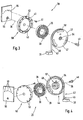
- Figure 1:
- a partially schematic top view of a mechanism for compensating the gravitational force acting on a slider of an electro-magnetic linear motor, wherein the slider is embodied here as a magnetic rod, which is taken up and mounted in the coil component of the stator and wherein the mechanism is fitted into a handling device of a fluid analysis device;
- Figure 2:
- a partially schematic top view of a mechanism for compensating the gravitational force acting on the slider of an electro-magnetic linear motor, wherein the slider is embodied here as a coil component, which takes up the magnetic rod of the stator and is mounted on it, wherein the mechanism is also fitted into a handling device of a fluid analysis device.
- Figure 3:
- an exploded drawing of the mechanism in a first view;
- Figure 4:
- an exploded drawing of the mechanism in a view rotated through 90° from Figure 3;
- Figure 5:
- a top view on a z-axis of a handling device with the mechanism in accordance with the invention for compensating the gravitational force acting on a slider of an electro-magnetic direct linear motor formed with a coil component;
- Figure 6:
- a three-dimensional view of the z-axis of the handling apparatus in accordance with Figure 5.
- The
mechanism 20 for compensating thegravitational force 29 acting on aslider linear motor 26 and acting on a load to be carried and moved by it, capable of moving along atravel path 21, comprises as an essential construction element aspring element 28, which is embodied here as aspiral spring 35 with a flat spring. Thelinear motor 26 is embodied as an electro-magnetic directlinear motor 27 and in this case as a permanently excited, two-phase synchronous motor with astator slider spiral spring 35 is received in ahousing 41, which is in turn received in thedrum 37 rotatable around therotational axis 36. In the fitted condition, thespiral spring 35 is supported at itsouter end 39 against asupport component 40, formed like a nose, of the adjustingbody 50 formed with thehousing 41, whilst theinside end 38 of thespiral spring 35 is supported against the supportingpart 57, formed in the shape of a recess, of thedrum 37. As shown by the Figures, in its fitted condition, thespiral spring 35 is completely received within thedrum 37. - The
drum 37 exhibits afront wall 47 formed vertical to therotational axis 36. Thefront wall 47 is embodied like a circular plate and at its periphery edges, passes into thecylindrical drum wall 48, formed like a tube and extending parallel to therotational axis 36. Thedrum wall 48 exhibits a cross-section and has a local opening, extending in the direction of the periphery, for receiving a fixing bolt. This receives the drum-side end 44 of a connectingelement 42 embodied as astrip 43, which is folded around the bolt for securing to thedrum wall 48. Thestrip 43 is preferably embodied with a textile belt with a hook on the end side. As shown in particular from Figure 3 and 4, thestrip 43, which exhibits sufficient length to guarantee thetravel path 21, is wound on thedrum 37, where it lies adjacent to the-outer periphery 46 of thedrum wall 48. The drum diameter and the strip length are embodied matching thetravel path 21 in such a way that thestrip 43, using almost the entire periphery of the drum, can be wound around thedrum 37, without two parts of the strip overlapping each other. This creates a constant arm, which means that constant force or moment ratios are guaranteed. - The
housing 41 is part of an adjustingbody 50, which serves to enable a precise positioning of the zero point of a body fixable to thefree end 45 of thestrip 43 via the connectingpiece 31, or the load, in such a way that the connectingpiece 31 is located in a basic position around the centre of the maximumpossible travel path 21. This position can be achieved by thehousing 41 being rotated manually around therotational axis 36, until the desired zero point position is reached. This rotational position of the housing can then be locked against torsion using a fixing means embodied in this case with ascrew 51. For this purpose, the housing wall exhibits a majority of through bore holes created here at equal distances along the periphery, running parallel to the rotational axis. Thescrew 51 can be inserted through one of these bore holes and then screwed into one of theopenings 53 in the holdingplate 55. Theopenings 53 are offset against each other at equal angular distances and arranged at the same radius as the continuous bore holes 52. However, the angular distances of theopenings 53 are smaller here than the angular distances between the bore holes 52. This enables a precisely adjustable zero point position to be achieved in defined specified yet small distances. - As shown by Figure 3, the holding
plate 55 exhibits the bearingsleeve 56, on which thehousing 41 of the adjustingbody 50 is mounted via a suitably formed bearing opening. With the aid of the two exploded diagrams shown in Figures 3 and 4, it can clearly be seen that to install and/or remove the mechanism, a bearingbolt 49 is used, which receives aball bearing 54, onto which thedrum 37 is rotatably mounted and which can be inserted and screwed through the bearingsleeve 56. In order to make an adjustment to the zero point position from outside when themechanism 20 is in the fitted condition, theend wall 47 of thedrum 37 exhibits, in the area of the internal fixingscrew 51, here threeelongated holes 58 arranged offset to each other at equal angular distances. A suitable operating tool, for example an inserting key for screwing and/or unscrewing thescrew 51 fitted with a hexagon socket can be inserted through these elongated holes. - Figures 1 and 2 each show two alternative options for fixing the connecting
piece 31 provided at the free end of thestrip 43 to aslider linear motor 26. - As shown by Figure 1, connected to the connecting
piece 31 is the end of aslider 22, which embodies here themagnetic rod 23 of an electro-magnetic directlinear motor 27. Themagnetic rod 23 is received into thecoil component 25 of thestator 24 of thelinear motor 26 and mounted there with a small degree of play. In contrast, thestator 24 is firmly connected to the holdingplate 55 via theyoke 33 so that these elements consequently remain fixed. In the design example shown in Figure 1, themagnet rod 23 can be translationally moved along thetravel path 21 and relative to thecoil component 25 embodied as astator 24. - In contrast, according to the design example shown in Figure 2, the
magnetic rod 23 is securely connected to theyoke 33, i.e. in this case, themagnetic rod 23 forms thestator 34. Accordingly in this design example, theslider 32 is embodied with thecoil component 25, which receives themagnetic rod 23 of thestator 34 and which is mounted on it with a small degree of play. - Figures 5 and 6 show a preferred application example of the
mechanism 20. This is an application for what is referred to as an z-axis 60, to be mounted vertically, for ahandling apparatus 65. This type ofhandling apparatus 65 can be used, in accordance with a particularly preferred application, in afluid analysis device 70, in particular for micro-fluid analysis, for example for bio-analysis, where it is used to manipulate samples, sample analysis and/or removing or adding samples. Thefluid analysis device 70 is shown schematically in Figures 1 and 2 by dotted lines. - The vertical z-
axis 60 consists essentially from aguide rail 61 to which a runningcarriage 63 supporting themechanism 20 is guidably mounted by means of two opposingbearing rollers 62. Themechanism 20 is securely connected to theguide rail 61 and also to themagnetic rod 23, which also in this case forms the stator, by means of the holdingplate 55. For this purpose, themagnetic rod 23 exhibits at its upper end a fixing screw, wherein to improve clarity in Figure 4, theyoke 33 has been omitted. Accordingly, thecoil component 25 in the design examples shown in Figure 5 and 6 embodies the slider, which is securely connected to the runningcarriage 63. The electrical connection of thelinear motor 26 is created by means of the strip-shapedelectrical cable 64, which is designed to have a length matching that of themaximum travel path 21. - In the design examples shown in Figure 5 and 6, the
linear motor 26 allows a maximum holding force of 33 Newton and a permanent force of 9 Newton, wherein the entire system can be used in a temperature range of between 0° Celsius and up to approximately 50° Celsius. In combination with themechanism 20 for compensating the gravitational force, the operating point of system can be accurately set, wherein the following characteristic data is achieved:travel path 21 or stroke of up to around 150 mm; loads of up to around 2 kg; small, compact device dimensions, as particularly used in laboratories. - The compact structure of the
linear motor 26 and the compact arrangement, together with the gravitationalforce compensation mechanism 20, contribute towards achieving a compact z-axis 60. At the same time, the drive, with the describedmechanism 20, the guide rails 61 and thecarriage 63 are accommodated within a square cross-section of 148 x 55 mm. Given a guide length of themagnetic rod 23 of around 300 mm, a stroke of around 160 mm is achieved, without the components projecting beyond the outline of the z-axis.
Claims (11)
- A mechanism for compensating the gravitational force (29) acting on a slider (22, 32) of a linear motor (26), in particular of an electro-magnetic direct linear motor (27), and acting on a load to be carried and moved by the slider (22, 32), capable of moving along a travel path (21),
characterized in that
a spring element (28) is provided ,which exerts on the slider (22,32) an elastic restoring force (30) opposite the gravitational force (29). - A mechanism in accordance with Claim 1, characterized in that the restoring force (30) of the spring element (28) is coordinated with and preferably adjustable to the mass of the slider (22,23) and the load in such a way that the slider (22,32) can be brought into a state of balance.
- A mechanism in accordance with either Claim 1 or 2, characterized in that the restoring force (30) of the spring element (28) is essentially constant over the travel path (21) of the slider (22,32).
- A mechanism in accordance with one of the Claims 1-3, characterized in that the spring element (28) is embodied with a torsional or spiral spring (35).
- A mechanism in accordance with Claim 4, characterized in that the spiral spring (35) is mounted in a drum (37) rotatable on a rotational axis (36), wherein the spiral spring (35) is supported at one of its ends against the drum (37) and at its other end against a support component (40) connected to a stator (24,34) of the linear motor (26).
- A mechanism in accordance with Claim 5, characterized in that a connecting element (42) which can be rolled up, is attached at one of its ends to the drum (37) and at its other end to the slider (22,32) of the linear motor (26).
- A mechanism in accordance with Claim 6, characterized in that the connecting element (42) is embodied as a strip (43) or cable that can be rolled up on an outer periphery (46) of the drum (37).
- A mechanism in accordance with one of the Claims 5-7, characterized in that the support component (40) is attached to an adjusting body (50) which is rotatable on a rotational axis (36) and preferably designed with a housing (41) for receiving the spiral spring (35) and which is lockable against torsion at various positions of angular rotation with the aid of a fixing device (51).
- A mechanism in accordance with one of the Claims 1-8, characterized in that the slider (22,32), preferably embodied as a coil component (25), takes up the stator (24,34) in the form of a tube or rod (23) and is mounted on it.
- A mechanism in accordance with one of the Claims 1-8, characterized in that the slider (22,32), preferably embodied as a magnetic component, is in the form of a tube or rod (23), which is taken up and mounted in the stator (24,34).
- A fluid analysis device, particularly for micro-fluid analysis, for example for bio-analysis, with a handling device (65) which contains a mechanism (20) in accordance with one of the Claims 1-10.
Priority Applications (3)
| Application Number | Priority Date | Filing Date | Title |
|---|---|---|---|
| DE60104321T DE60104321T2 (en) | 2001-12-14 | 2001-12-14 | Gravity compensation device for linear motor driven sliding element |
| EP01129774A EP1320178B1 (en) | 2001-12-14 | 2001-12-14 | Mechanism for compensating the gravitational force acting on a slider of a linear motor |
| US10/185,505 US6809435B2 (en) | 2001-12-14 | 2002-06-28 | Mechanism for compensating the gravitational force acting on a slider of a linear motor |
Applications Claiming Priority (1)
| Application Number | Priority Date | Filing Date | Title |
|---|---|---|---|
| EP01129774A EP1320178B1 (en) | 2001-12-14 | 2001-12-14 | Mechanism for compensating the gravitational force acting on a slider of a linear motor |
Publications (2)
| Publication Number | Publication Date |
|---|---|
| EP1320178A1 EP1320178A1 (en) | 2003-06-18 |
| EP1320178B1 true EP1320178B1 (en) | 2004-07-14 |
Family
ID=8179536
Family Applications (1)
| Application Number | Title | Priority Date | Filing Date |
|---|---|---|---|
| EP01129774A Revoked EP1320178B1 (en) | 2001-12-14 | 2001-12-14 | Mechanism for compensating the gravitational force acting on a slider of a linear motor |
Country Status (3)
| Country | Link |
|---|---|
| US (1) | US6809435B2 (en) |
| EP (1) | EP1320178B1 (en) |
| DE (1) | DE60104321T2 (en) |
Families Citing this family (5)
| Publication number | Priority date | Publication date | Assignee | Title |
|---|---|---|---|---|
| GB2478302B (en) | 2010-03-02 | 2012-02-15 | Cinetic Landis Ltd | A machine axis including a counterbalance and methods of operation thereof |
| AT513617B1 (en) | 2012-12-21 | 2014-06-15 | Seh Ltd | Magnetic device comprising an acceleration unit acting on the translator |
| WO2016187211A1 (en) | 2015-05-19 | 2016-11-24 | The Regents Of The University Of California | Dna structured linear actuator |
| CN108023460A (en) * | 2018-02-02 | 2018-05-11 | 上海莫戈纳机电科技有限公司 | Linear electric machine |
| US11915863B2 (en) | 2019-02-01 | 2024-02-27 | Zaber Technologies Inc. | Adjustable magnetic counterbalance |
Family Cites Families (15)
| Publication number | Priority date | Publication date | Assignee | Title |
|---|---|---|---|---|
| US4188552A (en) * | 1977-10-26 | 1980-02-12 | Linear International Corporation | Garage door opener including a linear actuator |
| US4215283A (en) * | 1978-05-03 | 1980-07-29 | Hinds Walter E | Linear stepping motor |
| JPS61247265A (en) * | 1985-04-23 | 1986-11-04 | Yaskawa Electric Mfg Co Ltd | Linear driving gear |
| US5297658A (en) * | 1992-10-07 | 1994-03-29 | Otis Elevator Company | Roller cam adjuster for linear motors |
| JPH07115056A (en) * | 1993-10-15 | 1995-05-02 | Canon Inc | Vertical substrate stage device |
| JPH08275453A (en) * | 1995-03-31 | 1996-10-18 | Oriental Motor Co Ltd | Braking mechanism of cylindrical linear pulse motor |
| US5668421A (en) * | 1995-04-06 | 1997-09-16 | E. B. Eddy Forest Products Ltd. | Pressurized air-gap guided active linear motor suspension system |
| JPH08339644A (en) * | 1995-06-06 | 1996-12-24 | Hewlett Packard Co <Hp> | Disk device with rigid actuator arm structure |
| US5817954A (en) * | 1995-10-09 | 1998-10-06 | Korea Ocean Research & Development Institute | Automated analyzing apparatus for measuring water quality with a cylinder-shaped syringe unit |
| US5726508A (en) * | 1995-12-06 | 1998-03-10 | Systems, Machines, Automation Components Corporation | Linear voice coil retractor |
| US5909710A (en) * | 1997-08-15 | 1999-06-08 | Cummins; Richard D. | Air-levitated train |
| JPH11287880A (en) * | 1998-04-01 | 1999-10-19 | Canon Inc | Stage device, aligner using the device and device production method |
| DE19963893A1 (en) * | 1999-12-30 | 2001-07-12 | Bison Stematec Maschb Und Huba | Drive device |
| JP2001230305A (en) * | 2000-02-18 | 2001-08-24 | Canon Inc | Supporting apparatus |
| US6664702B2 (en) * | 2000-12-11 | 2003-12-16 | Dpd, Inc. | Pseudoelastic springs with concentrated deformations and applications thereof |
-
2001
- 2001-12-14 EP EP01129774A patent/EP1320178B1/en not_active Revoked
- 2001-12-14 DE DE60104321T patent/DE60104321T2/en not_active Expired - Fee Related
-
2002
- 2002-06-28 US US10/185,505 patent/US6809435B2/en not_active Expired - Fee Related
Also Published As
| Publication number | Publication date |
|---|---|
| US6809435B2 (en) | 2004-10-26 |
| US20030111913A1 (en) | 2003-06-19 |
| DE60104321D1 (en) | 2004-08-19 |
| EP1320178A1 (en) | 2003-06-18 |
| DE60104321T2 (en) | 2005-08-04 |
Similar Documents
| Publication | Publication Date | Title |
|---|---|---|
| US9590471B2 (en) | Rotary lifting device | |
| JPH09100888A (en) | Electric actuator | |
| EP2071343B1 (en) | Self-guiding instrument carrier for in-situ operation in a generator | |
| DE69432192T2 (en) | linear actuator | |
| US5481929A (en) | Instrument holder and method for inspection of a dynamo-electric machine in a gap between a stator and a rotor and dynamo-electric machine having the instrument holder | |
| US20190152067A1 (en) | Gripping tool, gripping device, and gripping method | |
| CN1689704A (en) | Tube-plug extracting apparatus | |
| CA2410333C (en) | A robotic device for loading laboratory instruments | |
| WO2000014431A1 (en) | Motor-driven actuator | |
| EP1320178B1 (en) | Mechanism for compensating the gravitational force acting on a slider of a linear motor | |
| CN112010027B (en) | Crucible carrying clamping jaw mechanism | |
| WO2007149854A2 (en) | Vehicle tie rod adjustment device | |
| CN112260588A (en) | Magnetic driving device | |
| CN101019197B (en) | Energy accumulator | |
| US20080168914A1 (en) | Device with Several Rollers | |
| DE19931723C1 (en) | Toggle lever clamping assembly for bodywork sections in the automotive industry has a permanent magnet brake to secure the sections on a power failure even when carrying loads | |
| CN1078838C (en) | Industrial robot | |
| US5060533A (en) | Arm fitting structure of horizontal articulated robot | |
| CN110576083A (en) | bending device | |
| SE456027B (en) | HANGERS FOR MOTOR VEHICLES | |
| CN214030775U (en) | Crucible carrying clamping jaw mechanism | |
| CN210800625U (en) | Fixing support for optical instrument | |
| EP1619339B1 (en) | System to make a trolley slide into a profile and profile so realized | |
| DE102008038758A1 (en) | Electrical rotary-lift-drive for use in assembly head for handling and positioning tasks, has hollow shaft guided in bearing, which is formed for guidance of hollow shaft in axial and radial directions | |
| CN219986780U (en) | Shaft and bearing alignment assembling device |
Legal Events
| Date | Code | Title | Description |
|---|---|---|---|
| PUAI | Public reference made under article 153(3) epc to a published international application that has entered the european phase |
Free format text: ORIGINAL CODE: 0009012 |
|
| AK | Designated contracting states |
Designated state(s): AT BE CH CY DE DK ES FI FR GB GR IE IT LI LU MC NL PT SE TR |
|
| AX | Request for extension of the european patent |
Extension state: AL LT LV MK RO SI |
|
| 17P | Request for examination filed |
Effective date: 20030806 |
|
| 17Q | First examination report despatched |
Effective date: 20031006 |
|
| GRAP | Despatch of communication of intention to grant a patent |
Free format text: ORIGINAL CODE: EPIDOSNIGR1 |
|
| GRAP | Despatch of communication of intention to grant a patent |
Free format text: ORIGINAL CODE: EPIDOSNIGR1 |
|
| AKX | Designation fees paid |
Designated state(s): DE FR GB |
|
| GRAS | Grant fee paid |
Free format text: ORIGINAL CODE: EPIDOSNIGR3 |
|
| GRAA | (expected) grant |
Free format text: ORIGINAL CODE: 0009210 |
|
| AK | Designated contracting states |
Kind code of ref document: B1 Designated state(s): DE FR GB |
|
| PG25 | Lapsed in a contracting state [announced via postgrant information from national office to epo] |
Ref country code: FR Free format text: LAPSE BECAUSE OF FAILURE TO SUBMIT A TRANSLATION OF THE DESCRIPTION OR TO PAY THE FEE WITHIN THE PRESCRIBED TIME-LIMIT Effective date: 20040714 |
|
| REG | Reference to a national code |
Ref country code: GB Ref legal event code: FG4D |
|
| REF | Corresponds to: |
Ref document number: 60104321 Country of ref document: DE Date of ref document: 20040819 Kind code of ref document: P |
|
| REG | Reference to a national code |
Ref country code: IE Ref legal event code: FG4D |
|
| PGFP | Annual fee paid to national office [announced via postgrant information from national office to epo] |
Ref country code: FR Payment date: 20041217 Year of fee payment: 4 |
|
| PLAQ | Examination of admissibility of opposition: information related to despatch of communication + time limit deleted |
Free format text: ORIGINAL CODE: EPIDOSDOPE2 |
|
| PLBQ | Unpublished change to opponent data |
Free format text: ORIGINAL CODE: EPIDOS OPPO |
|
| PLAQ | Examination of admissibility of opposition: information related to despatch of communication + time limit deleted |
Free format text: ORIGINAL CODE: EPIDOSDOPE2 |
|
| PLAR | Examination of admissibility of opposition: information related to receipt of reply deleted |
Free format text: ORIGINAL CODE: EPIDOSDOPE4 |
|
| PLBI | Opposition filed |
Free format text: ORIGINAL CODE: 0009260 |
|
| PLBQ | Unpublished change to opponent data |
Free format text: ORIGINAL CODE: EPIDOS OPPO |
|
| PLAX | Notice of opposition and request to file observation + time limit sent |
Free format text: ORIGINAL CODE: EPIDOSNOBS2 |
|
| 26 | Opposition filed |
Opponent name: FESTO AG & CO Effective date: 20050413 |
|
| EN | Fr: translation not filed | ||
| PLBP | Opposition withdrawn |
Free format text: ORIGINAL CODE: 0009264 |
|
| PGFP | Annual fee paid to national office [announced via postgrant information from national office to epo] |
Ref country code: GB Payment date: 20051207 Year of fee payment: 5 |
|
| PGFP | Annual fee paid to national office [announced via postgrant information from national office to epo] |
Ref country code: DE Payment date: 20060131 Year of fee payment: 5 |
|
| RAP2 | Party data changed (patent owner data changed or rights of a patent transferred) |
Owner name: AGILENT TECHNOLOGIES, INC. |
|
| PG25 | Lapsed in a contracting state [announced via postgrant information from national office to epo] |
Ref country code: DE Free format text: LAPSE BECAUSE OF NON-PAYMENT OF DUE FEES Effective date: 20070703 |
|
| GBPC | Gb: european patent ceased through non-payment of renewal fee |
Effective date: 20061214 |
|
| PG25 | Lapsed in a contracting state [announced via postgrant information from national office to epo] |
Ref country code: GB Free format text: LAPSE BECAUSE OF NON-PAYMENT OF DUE FEES Effective date: 20061214 |
|
| RDAF | Communication despatched that patent is revoked |
Free format text: ORIGINAL CODE: EPIDOSNREV1 |
|
| RDAG | Patent revoked |
Free format text: ORIGINAL CODE: 0009271 |
|
| STAA | Information on the status of an ep patent application or granted ep patent |
Free format text: STATUS: PATENT REVOKED |
|
| 27W | Patent revoked |
Effective date: 20091214 |