EP1320161B1 - Apparatus support for cable channels - Google Patents
Apparatus support for cable channels Download PDFInfo
- Publication number
- EP1320161B1 EP1320161B1 EP02023320A EP02023320A EP1320161B1 EP 1320161 B1 EP1320161 B1 EP 1320161B1 EP 02023320 A EP02023320 A EP 02023320A EP 02023320 A EP02023320 A EP 02023320A EP 1320161 B1 EP1320161 B1 EP 1320161B1
- Authority
- EP
- European Patent Office
- Prior art keywords
- hood
- hooks
- base part
- bottom plate
- apparatus support
- Prior art date
- Legal status (The legal status is an assumption and is not a legal conclusion. Google has not performed a legal analysis and makes no representation as to the accuracy of the status listed.)
- Expired - Lifetime
Links
Images
Classifications
-
- H—ELECTRICITY
- H02—GENERATION; CONVERSION OR DISTRIBUTION OF ELECTRIC POWER
- H02G—INSTALLATION OF ELECTRIC CABLES OR LINES, OR OF COMBINED OPTICAL AND ELECTRIC CABLES OR LINES
- H02G3/00—Installations of electric cables or lines or protective tubing therefor in or on buildings, equivalent structures or vehicles
- H02G3/02—Details
- H02G3/08—Distribution boxes; Connection or junction boxes
- H02G3/10—Distribution boxes; Connection or junction boxes for surface mounting on a wall
- H02G3/105—Distribution boxes; Connection or junction boxes for surface mounting on a wall in association with a plinth, channel, raceway or similar
Definitions
- the invention relates to equipment rack according to the preamble of claim 1 for the installation of electrical installation equipment in addition to vertically or horizontally routed cable trunking, in particular baseboard channels.
- a device carrier according to the preamble of claim 1 is known from EP-A-1 137 142.
- the device carrier has a base part, which is fastened to the wall in addition to the baseboard channel what are provided in the bottom plate openings for screws and dowels.
- the electrical installation device which is provided with corresponding means, is attached.
- the gear tray is completed by a cover, which covers the base plate and the electrical installation device.
- a commercial type of electrical installation equipment has an approximately cuboid housing with a rectangular or square plan, on which right and left projecting a retaining tab is formed.
- a device carrier four mounted on the bottom plate latch hooks.
- the latching hooks are resilient. If now a firmly seated plug is pulled out of a latched socket, considerable forces act on the latching hooks. Since these springs, they can dodge to the side, whereupon the installation device detaches itself from the device carrier. Thus, the live cables and contacts are directly accessible, the electrical safety is no longer given. That is inadmissible.
- the present invention is therefore an object of the invention to improve a device carrier of the type mentioned in such a way that the snapped electrical appliances can not solve unintentionally even with large tensile forces.
- the main advantage of the present invention is that with the hood removed, the electric device holding latch hooks can spring freely, making the electrical device very easy to assemble and disassemble again if necessary, and that when snapping the hood on the base part, the locking hooks through the inside of the hood molded noses are blocked. Unintentional release of the electrical device is therefore excluded with attached hood. Locking screws are not required.
- the latching hooks are mounted on spring strips, comparable to the construction described in FR 27 70 047 A or EP 1 087 486 A.
- the noses formed on the inside of the hood can also block these spring strips.
- the cable guide channel adjacent latching hook is rigid. This takes into account the fact that this locking hook can be difficult to be blocked with the help of formed on the hood nose, because at this point the lines are inserted from the channel in the equipment carrier and vice versa.
- the locking hook opposite the locking hooks equipped with an extended suspension.
- hooks, ribs and / or eyes are integrally formed on the base part and on the hood, which allow the detachable attachment of the hood.
- the hood can be mounted very quickly and at the same time secured against accidental loosening.
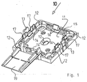
- Fig. 1 shows an isometric view of a base part 10 of a device carrier for the installation of electrical installation equipment in addition to vertically or horizontally routed cable trunking.
- the base part 10 has a bottom plate 11 with mounting holes 12 for wall mounting.
- guide rails 13 for a hood 20 (FIGS. 2 and 3) to be placed on the base part 10 are integrally formed on the base plate 11.
- hooks 17 are formed in addition to the guide rails 13, which correspond with corresponding hooks 27 and eyelets on the hood 20.
- apron 19 On the underside of the bottom plate 11 can be seen an apron 19, in a conventional manner a wiring channel (not shown), z. B. a baseboard channel, engages and thus causes the required system separation of the lead-out lines.
- the latching hook 14 'adjacent to the skirt 19 is, unlike the other latching hooks 14, 14 ", not springy but rigid .. Since lines are inserted and removed in the area of the skirt 19, these could prevent the hood 20 from being able to be put on. To compensate for the rigid latching hook 14 'opposite latching hook 14 "is equipped with an extended suspension. It is thus easily possible to mount the electrical device and possibly also to solve again.
- each a pair of hooks 27 which correspond to the hooks 17 on the base part 10 and are together responsible for the snap-fastening of the hood 20 on the base part 10.
Landscapes
- Engineering & Computer Science (AREA)
- Architecture (AREA)
- Civil Engineering (AREA)
- Structural Engineering (AREA)
- Casings For Electric Apparatus (AREA)
- Connections Arranged To Contact A Plurality Of Conductors (AREA)
- Laminated Bodies (AREA)
- Polyesters Or Polycarbonates (AREA)
- Details Of Connecting Devices For Male And Female Coupling (AREA)
- Linear Motors (AREA)
- Connector Housings Or Holding Contact Members (AREA)
- Laying Of Electric Cables Or Lines Outside (AREA)
- Communication Cables (AREA)
- Multi-Conductor Connections (AREA)
Abstract
Description
Die Erfindung betrifft Geräteträger gemäß dem Oberbegriff des Anspruchs 1 für die Montage von Elektro-Installationsgeräten neben senkrecht oder waagerecht verlegten Leitungsführungskanälen, insbesondere Sockelleistenkanälen.The invention relates to equipment rack according to the preamble of claim 1 for the installation of electrical installation equipment in addition to vertically or horizontally routed cable trunking, in particular baseboard channels.
Ein Geräteträger gemäß dem Oberbegriff des Anspruchs 1 ist aus EP-A-1 137 142 bekannt.A device carrier according to the preamble of claim 1 is known from EP-A-1 137 142.
Um Elektro-Installationsgeräte, z. B. Steckdosen, an einem Sockelleistenkanal anzubringen, werden spezielle Geräteträger verwendet. Man vergleiche EP 0 159 554 A, EP 0 239 456 A, FR 27 70 047 A oder EP 0 702 442 B oder EP 0 187 486 A. In allen Fällen besitzt der Geräteträger ein Basisteil, welches neben dem Sockelleistenkanal an der Wand befestigt wird, wozu in der Bodenplatte Öffnungen für Schrauben und Dübel vorgesehen sind. Auf der Bodenplatte sind Vorrichtungen vorgesehen, an denen das Elektro-Installationsgerät, welches mit korrespondierenden Einrichtungen versehen ist, befestigt wird. Komplettiert wird der Geräteträger durch eine Abdeckhaube, die Bodenplatte und Elektro-Installationsgerät überdeckt.To electrical installation equipment, eg. As sockets to attach to a baseboard channel, special equipment carriers are used. Compare EP 0 159 554 A, EP 0 239 456 A,
Eine handelsübliche Art von Elektro-Installationsgeräten besitzt ein etwa quaderförmiges Gehäuse mit rechteckigem oder quadratischem Grundriss, an dem recht und links abstehend eine Haltelasche angeformt ist. Zur Befestigung eines solchen Installationsgerätes besitzen die in der FR 27 70 047 A sowie in der EP 1 087 486 A beschriebenen Geräteträger vier auf der Bodenplatte befestigte Rasthaken. Um das Einschnappen der Haltelaschen zu ermöglichen, sind die Rasthaken federnd. Wird nun aus einer aufgerasteten Steckdose ein fest sitzender Stecker herausgezogen, so wirken erhebliche Kräfte auf die Rasthaken. Da diese federn, können sie zur Seite ausweichen, worauf sich das Installationsgerät vom Geräteträger löst. Damit sind die spannungsführenden Leitungen und Kontakte direkt zugänglich, die elektrische Sicherheit ist nicht mehr gegeben. Das ist unzulässig.A commercial type of electrical installation equipment has an approximately cuboid housing with a rectangular or square plan, on which right and left projecting a retaining tab is formed. To fix such an installation device have described in
Um zu verhindern, dass sich das Elektrogerät wie beschrieben in unerwünschter Weise vom Geräteträger lösen kann, wird in der FR-A 27 70 047 vorgeschlagen, die Haube mit dem Basisteil zu verschrauben. Dazu ist die Haube mit Schrauböffnungen, das Basisteil mit korrespondierenden Gewindepfosten ausgerüstet. Eine solche Schraubbefestigung ist zwar stabil, jedoch zeit- und damit kostenaufwändig. Außerdem wird das Anbringen der Sicherungsschrauben oft vergessen. Das ist unbefriedigend.In order to prevent the electrical appliance as described can solve undesirably from the equipment rack, in FR-
Der vorliegenden Erfindung liegt daher die Aufgabe zugrunde, einen Geräteträger der eingangs genannten Art dahingehend zu verbessern, dass sich die aufgeschnappten Elektrogeräte auch bei großen Zugkräften nicht unbeabsichtigt lösen können.The present invention is therefore an object of the invention to improve a device carrier of the type mentioned in such a way that the snapped electrical appliances can not solve unintentionally even with large tensile forces.
Diese Aufgabe wird gelöst durch einen Geräteträger mit den Merkmalen des Anspruchs 1.This object is achieved by a device carrier with the features of claim 1.
Der wesentliche Vorteil der vorliegenden Erfindung besteht darin, dass bei abgenommener Haube die das Elektrogerät haltenden Rasthaken frei federn können, wodurch sich das Elektrogerät besonders einfach montieren sowie bei Bedarf auch wieder demontieren lässt, und dass beim Aufrasten der Haube auf das Basisteil die Rasthaken durch an der Innenseite der Haube angeformte Nasen blockiert werden. Ein unbeabsichtigtes Lösen des Elektrogerätes ist daher bei aufgesetzter Haube ausgeschlossen. Sicherungsschrauben sind nicht erforderlich.The main advantage of the present invention is that with the hood removed, the electric device holding latch hooks can spring freely, making the electrical device very easy to assemble and disassemble again if necessary, and that when snapping the hood on the base part, the locking hooks through the inside of the hood molded noses are blocked. Unintentional release of the electrical device is therefore excluded with attached hood. Locking screws are not required.
Gemäß einer Ausgestaltung der Erfindung sind die Rasthaken auf Federleisten gelagert, vergleichbar der in der FR 27 70 047 A oder der EP 1 087 486 A beschriebenen Konstruktion. In diesem Fall können die an der Innenseite der Haube angeformten Nasen auch diese Federleisten blockieren.According to one embodiment of the invention, the latching hooks are mounted on spring strips, comparable to the construction described in
Gemäß einer bevorzugten Ausgestaltung der Erfindung ist der dem Leitungsführungskanal benachbarte Rasthaken starr. Damit wird der Tatsache Rechnung getragen, dass dieser Rasthaken nur schwer mit Hilfe von an der Haube angeformten Nasen blockiert werden kann, weil an dieser Stelle die Leitungen aus dem Kanal in den Geräteträger eingeführt werden und umgekehrt.According to a preferred embodiment of the invention, the cable guide channel adjacent latching hook is rigid. This takes into account the fact that this locking hook can be difficult to be blocked with the help of formed on the hood nose, because at this point the lines are inserted from the channel in the equipment carrier and vice versa.
Um auch in diesem Fall das Aufsetzen und wieder Lösen des Elektrogerätes auf dem bzw. von dem Geräteträger bei abgenommener Haube bequem durchführen zu können, ist gemäß einer Weiterbildung der Erfindung der dem starren Rasthaken gegenüberliegende Rasthaken mit einer erweiterten Federung ausgerüstet.In order to comfortably carry out in this case, the putting on and releasing the electrical appliance on or from the equipment rack with the hood removed can, according to a development of the invention, the locking hook opposite the locking hooks equipped with an extended suspension.
Vorteilhafterweise sind am Basisteil und an der Haube Haken, Rippen und/oder Ösen angeformt, die die lösbare Befestigung der Haube ermöglichen. Auf diese Weise lässt sich die Haube besonders schnell montieren und ist gleichzeitig gegen ein ungewolltes Lösen gesichert.Advantageously, hooks, ribs and / or eyes are integrally formed on the base part and on the hood, which allow the detachable attachment of the hood. In this way, the hood can be mounted very quickly and at the same time secured against accidental loosening.
Anhand der Zeichnung soll die Erfindung in Form eines Ausführungsbeispiels näher erläutert werden. Es zeigen jeweils in isometrischer Darstellung
- Fig. 1
- ein Basisteil eines Geräteträgers,
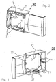
- Fig. 2
- die Außenseite einer Haube für den Geräteträger der Fig. 1 und
- Fig. 3
- die Innenseite der Haube nach Fig. 2.
- Fig. 1
- a base part of a device carrier,
- Fig. 2
- the outside of a hood for the equipment carrier of Fig. 1 and
- Fig. 3
- the inside of the hood of FIG. 2.
Fig. 1 zeigt in isometrischer Darstellung ein Basisteil 10 eines Geräteträgers für die Montage von Elektro-Installationsgeräten neben senkrecht oder waagerecht verlegten Leitungsführungskanälen. Das Basisteil 10 besitzt eine Bodenplatte 11 mit Befestigungsöffnungen 12 für eine Wandbefestigung. Rechts und links sind an der Bodenplatte 11 Führungsschienen 13 für eine auf das Basisteil 10 aufzusetzende Haube 20 (Fig. 2 und 3) angeformt. Für eine Rastbefestigung der Haube 20 sind neben den Führungsschienen 13 Haken 17 angeformt, die mit entsprechenden Haken 27 bzw. Ösen an der Haube 20 korrespondieren.Fig. 1 shows an isometric view of a
An der Unterseite der Bodenplatte 11 erkennt man eine Schürze 19, die in an sich bekannter Weise einen Leitungsführungskanal (nicht dargestellt), z. B. einen Sockelleistenkanal, übergreift und so die erforderliche Systemtrennung der herausgeführten Leitungen bewirkt.On the underside of the
Für eine Rastbefestigung von handelsüblichen Elektro-Installationsgeräten, die mit radial abstehenden Haltelaschen ausgerüstet sind, sind auf der Bodenplatte 11 vier federnde Rasthaken 14, 14', 14" errichtet. Zwecks Verbesserung der Federung sind die Rasthaken 14, 14" auf Federleisten 15 gelagert. Soll ein Elektro-Installationsgerät montiert werden, so wird es einfach von oben auf die Bodenplatte 11 gedrückt. Dabei weichen die federnden Rasthaken 14, 14" zunächst zur Seite aus. Sobald das Elektrogerät korrekt sitzt, federn die Rasthaken 14, 14" wieder zurück und halten das Gerät fest.For a latching attachment of commercial electrical installation equipment, which are equipped with radially projecting retaining tabs, four
Allerdings hat die Erfahrung gezeigt, dass die Rasthaken 14, 14" auch dann wieder zurückweichen, wenn größere Zugkräfte, wie sie beispielsweise beim Ziehen eines fest sitzenden Steckers aus einer Steckdose auftreten, auf sie einwirken. Dabei könnte sich das Elektrogerät mitsamt der Haube 20 vom Basisteil 10 ungewollt lösen. Daraufhin wären die spannungsführenden Drähte und Kontakte frei zugänglich, es bestünde Lebensgefahr. Um dies zu verhindern, besitzt die in den Fig. 2 und 3 dargestellte, zum Basisteil 10 gehörende Haube 20 an ihrer Innenseite an die umlaufenden Wände 21 angeformte Nasen 24. Beim Aufsetzen der Haube 20 auf das Basisteil 10 fahren diese Nasen 24 hinter die Rasthaken 14, 14" und/oder hinter die Federleisten 15 und blockieren diese. Auf diese Weise können die Rasthaken 14, 14" auch bei großen Zugkräften nicht mehr ausweichen, das Elektrogerät sitzt unverrückbar fest auf dem Basisteil 10.However, experience has shown that the
Der der Schürze 19 benachbarte Rasthaken 14' ist im Gegensatz zu den übrigen Rasthaken 14, 14" nicht federnd sondern starr ausgeführt. Da im Bereich der Schürze 19 Leitungen ein- und ausgeführt werden, könnten diese verhindern, dass die Haube 20 aufgesetzt werden kann. Zum Ausgleich ist der dem starren Rasthaken 14' gegenüberliegende Rasthaken 14" mit einer erweiterten Federung ausgerüstet. Es ist somit ohne weiteres möglich, das Elektrogerät zu montieren und gegebenenfalls auch wieder zu lösen.The latching hook 14 'adjacent to the
Schließlich erkennt man an der Innenseite der umlaufenden Wände 21 rechts und links je ein Paar von Haken 27, die mit den Haken 17 am Basisteil 10 korrespondieren und mit diesen zusammen für die Rastbefestigung der Haube 20 auf dem Basisteil 10 verantwortlich sind.Finally, one recognizes on the inside of the
Claims (5)
- Apparatus support for mounting electrical installation apparatus next to vertically or horizontally installed wiring trunking, in particular skirting trunking, with an apron (19) which engages over the trunking, at least comprising- a base part (10) with-- a bottom plate (11),-- fastening openings (12) in the bottom plate,-- lateral guide rails (13) at the bottom plate (11)-- and resilient locking hooks (14, 14") for snap-fastening the electrical apparatus to the bottom plate (11)- and a hood (20) which can be mounted in a detachable manner on the base part (10) and hascharacterised by the feature:-- circumferential side walls (21)-- and a central cut-out (22) as access to the electrical apparatus,- lugs (24), which clamp the locking hooks (14, 14"), are formed on the inside of the hood (20).
- Apparatus support according to Claim 1, characterised by the features:- the locking hooks (14, 14") are mounted on spring strips (15),- the lugs (24) clamp the spring strips (15).
- Apparatus support according to Claim 1 or 2, characterised by the feature:- the locking hook (14') adjacent to the wiring trunking is rigid.
- Apparatus support according to Claim 3, characterised by the feature:- the locking hook (14") lying opposite the rigid locking hook (14') has increased resilience.
- Apparatus support according to any one of Claims 1 to 4, characterised by the feature:- hooks (17, 27), ribs and/or eyes are formed on the base part (10) and on the hood (20), these enabling the hood (20) to be fastened in a detachable manner.
Priority Applications (1)
| Application Number | Priority Date | Filing Date | Title |
|---|---|---|---|
| SI200230365T SI1320161T1 (en) | 2001-12-11 | 2002-10-18 | Apparatus support for cable channels |
Applications Claiming Priority (2)
| Application Number | Priority Date | Filing Date | Title |
|---|---|---|---|
| DE20120026U | 2001-12-11 | ||
| DE20120026U DE20120026U1 (en) | 2001-12-11 | 2001-12-11 | Equipment carrier for baseboard channels |
Publications (2)
| Publication Number | Publication Date |
|---|---|
| EP1320161A1 EP1320161A1 (en) | 2003-06-18 |
| EP1320161B1 true EP1320161B1 (en) | 2006-05-17 |
Family
ID=7965007
Family Applications (1)
| Application Number | Title | Priority Date | Filing Date |
|---|---|---|---|
| EP02023320A Expired - Lifetime EP1320161B1 (en) | 2001-12-11 | 2002-10-18 | Apparatus support for cable channels |
Country Status (7)
| Country | Link |
|---|---|
| EP (1) | EP1320161B1 (en) |
| AT (1) | ATE326785T1 (en) |
| DE (2) | DE20120026U1 (en) |
| DK (1) | DK1320161T3 (en) |
| ES (1) | ES2265015T3 (en) |
| PT (1) | PT1320161E (en) |
| SI (1) | SI1320161T1 (en) |
Families Citing this family (4)
| Publication number | Priority date | Publication date | Assignee | Title |
|---|---|---|---|---|
| DE102007020958A1 (en) | 2007-05-03 | 2008-11-06 | In-Akustik Gmbh & Co. Kg Unterhaltungselektronik | Device for installing power and data cables and system components |
| DE102008019763B4 (en) * | 2008-04-18 | 2019-02-21 | Phoenix Contact Gmbh & Co. Kg | Assembly with a fastening device for releasably latching holder of an electrical distributor |
| DE202011103720U1 (en) | 2011-07-27 | 2012-11-15 | Tehalit Gmbh | Device carrier with snap closure for mounting an electrical installation device to a cable trunking |
| DE202011108285U1 (en) | 2011-11-25 | 2013-02-27 | Tehalit Gmbh | Device carrier for mounting an electrical installation device to a cable trunking |
Family Cites Families (3)
| Publication number | Priority date | Publication date | Assignee | Title |
|---|---|---|---|---|
| FR2770047B1 (en) * | 1997-10-20 | 2000-01-28 | Planet Wattohm Sa | MOUNTING ADAPTER FOR ELECTRICAL APPARATUS WITH NON-SQUARE CONTOUR |
| FR2799058B1 (en) * | 1999-09-24 | 2001-11-23 | Rehau Sa | ADAPTER FOR ELECTRICAL EQUIPMENT HAVING A MOUNTING DIRECTION |
| FR2806847B1 (en) * | 2000-03-24 | 2002-10-04 | Legrand Sa | APPARATUS HOUSING AVAILABLE ALONG A CHUTE, ESPECIALLY FOR ELECTRIC APPARATUS |
-
2001
- 2001-12-11 DE DE20120026U patent/DE20120026U1/en not_active Expired - Lifetime
-
2002
- 2002-10-18 AT AT02023320T patent/ATE326785T1/en active
- 2002-10-18 PT PT02023320T patent/PT1320161E/en unknown
- 2002-10-18 EP EP02023320A patent/EP1320161B1/en not_active Expired - Lifetime
- 2002-10-18 ES ES02023320T patent/ES2265015T3/en not_active Expired - Lifetime
- 2002-10-18 SI SI200230365T patent/SI1320161T1/en unknown
- 2002-10-18 DE DE50206796T patent/DE50206796D1/en not_active Expired - Lifetime
- 2002-10-18 DK DK02023320T patent/DK1320161T3/en active
Also Published As
| Publication number | Publication date |
|---|---|
| DK1320161T3 (en) | 2006-09-18 |
| ES2265015T3 (en) | 2007-02-01 |
| ATE326785T1 (en) | 2006-06-15 |
| DE20120026U1 (en) | 2003-04-17 |
| EP1320161A1 (en) | 2003-06-18 |
| DE50206796D1 (en) | 2006-06-22 |
| SI1320161T1 (en) | 2006-10-31 |
| PT1320161E (en) | 2006-09-29 |
Similar Documents
| Publication | Publication Date | Title |
|---|---|---|
| DE10036727B4 (en) | Disposed cable tray, electrical outlet and procedure for installing them | |
| DE102013112101B4 (en) | Components Mounting System | |
| EP3066902B1 (en) | Function component upper part for a component construction system | |
| DE60118314T2 (en) | Electric motor vehicle junction box | |
| EP2038976A1 (en) | Connection box | |
| DE68903836T2 (en) | CONSUMER UNITS. | |
| DE202008001961U1 (en) | Contacting system for light bands or lights | |
| EP3066904B1 (en) | Functional component for a component construction system | |
| EP0702441B1 (en) | Electrical installation apparatus, especially for cable ducts | |
| DE69316548T2 (en) | Bushing arrangement | |
| EP1320161B1 (en) | Apparatus support for cable channels | |
| EP0917276A1 (en) | Casing for an electric motor | |
| EP1394916B1 (en) | Apparatus holder for use with electrical trunkings | |
| EP3419128A1 (en) | Power strip for a distribution box | |
| DE102016010713A1 (en) | Cable, device installation and installation trunking system | |
| DE202008015921U1 (en) | cabinet arrangement | |
| DE4013970C2 (en) | socket body | |
| EP0419719B1 (en) | Junction unit for joining and connecting electrical cables together | |
| EP1315262B1 (en) | Apparatus holder for cable channels | |
| DE4103852A1 (en) | FURNITURE BUILT-IN BOX | |
| AT405583B (en) | COMPONENT FOR ELECTRICAL INSTALLATIONS | |
| DE3808294C2 (en) | ||
| DE102013112104A1 (en) | Components Mounting System | |
| DE9404835U1 (en) | Component for electrical installations | |
| EP1403990A1 (en) | Electrical installation device |
Legal Events
| Date | Code | Title | Description |
|---|---|---|---|
| PUAI | Public reference made under article 153(3) epc to a published international application that has entered the european phase |
Free format text: ORIGINAL CODE: 0009012 |
|
| AK | Designated contracting states |
Designated state(s): AT BE BG CH CY CZ DE DK EE ES FI FR GB GR IE IT LI LU MC NL PT SE SK TR |
|
| AX | Request for extension of the european patent |
Extension state: AL LT LV MK RO SI |
|
| 17P | Request for examination filed |
Effective date: 20030723 |
|
| AKX | Designation fees paid |
Designated state(s): AT BE BG CH CY CZ DE DK EE ES FI FR GB GR IE IT LI LU MC NL PT SE SK TR |
|
| AXX | Extension fees paid |
Extension state: RO Payment date: 20030723 Extension state: SI Payment date: 20030723 |
|
| RAP1 | Party data changed (applicant data changed or rights of an application transferred) |
Owner name: TEHALIT GMBH |
|
| RAP1 | Party data changed (applicant data changed or rights of an application transferred) |
Owner name: TEHALIT GMBH |
|
| GRAP | Despatch of communication of intention to grant a patent |
Free format text: ORIGINAL CODE: EPIDOSNIGR1 |
|
| RTI1 | Title (correction) |
Free format text: APPARATUS SUPPORT FOR CABLE CHANNELS |
|
| GRAS | Grant fee paid |
Free format text: ORIGINAL CODE: EPIDOSNIGR3 |
|
| GRAA | (expected) grant |
Free format text: ORIGINAL CODE: 0009210 |
|
| AK | Designated contracting states |
Kind code of ref document: B1 Designated state(s): AT BE BG CH CY CZ DE DK EE ES FI FR GB GR IE IT LI LU MC NL PT SE SK TR |
|
| AX | Request for extension of the european patent |
Extension state: RO SI |
|
| PG25 | Lapsed in a contracting state [announced via postgrant information from national office to epo] |
Ref country code: IT Free format text: LAPSE BECAUSE OF FAILURE TO SUBMIT A TRANSLATION OF THE DESCRIPTION OR TO PAY THE FEE WITHIN THE PRESCRIBED TIME-LIMIT;WARNING: LAPSES OF ITALIAN PATENTS WITH EFFECTIVE DATE BEFORE 2007 MAY HAVE OCCURRED AT ANY TIME BEFORE 2007. THE CORRECT EFFECTIVE DATE MAY BE DIFFERENT FROM THE ONE RECORDED. Effective date: 20060517 Ref country code: SK Free format text: LAPSE BECAUSE OF FAILURE TO SUBMIT A TRANSLATION OF THE DESCRIPTION OR TO PAY THE FEE WITHIN THE PRESCRIBED TIME-LIMIT Effective date: 20060517 Ref country code: GB Free format text: LAPSE BECAUSE OF FAILURE TO SUBMIT A TRANSLATION OF THE DESCRIPTION OR TO PAY THE FEE WITHIN THE PRESCRIBED TIME-LIMIT Effective date: 20060517 Ref country code: IE Free format text: LAPSE BECAUSE OF FAILURE TO SUBMIT A TRANSLATION OF THE DESCRIPTION OR TO PAY THE FEE WITHIN THE PRESCRIBED TIME-LIMIT Effective date: 20060517 |
|
| REG | Reference to a national code |
Ref country code: GB Ref legal event code: FG4D Free format text: NOT ENGLISH |
|
| REG | Reference to a national code |
Ref country code: CH Ref legal event code: EP |
|
| REG | Reference to a national code |
Ref country code: IE Ref legal event code: FG4D Free format text: LANGUAGE OF EP DOCUMENT: GERMAN |
|
| REF | Corresponds to: |
Ref document number: 50206796 Country of ref document: DE Date of ref document: 20060622 Kind code of ref document: P |
|
| PG25 | Lapsed in a contracting state [announced via postgrant information from national office to epo] |
Ref country code: SE Free format text: LAPSE BECAUSE OF FAILURE TO SUBMIT A TRANSLATION OF THE DESCRIPTION OR TO PAY THE FEE WITHIN THE PRESCRIBED TIME-LIMIT Effective date: 20060817 |
|
| REG | Reference to a national code |
Ref country code: CH Ref legal event code: NV Representative=s name: PATENTANWAELTE SCHAAD, BALASS, MENZL & PARTNER AG |
|
| REG | Reference to a national code |
Ref country code: DK Ref legal event code: T3 |
|
| REG | Reference to a national code |
Ref country code: PT Ref legal event code: SC4A Effective date: 20060727 |
|
| REG | Reference to a national code |
Ref country code: GR Ref legal event code: EP Ref document number: 20060402742 Country of ref document: GR |
|
| GBV | Gb: ep patent (uk) treated as always having been void in accordance with gb section 77(7)/1977 [no translation filed] |
Effective date: 20060517 |
|
| ET | Fr: translation filed | ||
| REG | Reference to a national code |
Ref country code: IE Ref legal event code: FD4D |
|
| REG | Reference to a national code |
Ref country code: ES Ref legal event code: FG2A Ref document number: 2265015 Country of ref document: ES Kind code of ref document: T3 |
|
| PLBE | No opposition filed within time limit |
Free format text: ORIGINAL CODE: 0009261 |
|
| STAA | Information on the status of an ep patent application or granted ep patent |
Free format text: STATUS: NO OPPOSITION FILED WITHIN TIME LIMIT |
|
| 26N | No opposition filed |
Effective date: 20070220 |
|
| PG25 | Lapsed in a contracting state [announced via postgrant information from national office to epo] |
Ref country code: TR Free format text: LAPSE BECAUSE OF FAILURE TO SUBMIT A TRANSLATION OF THE DESCRIPTION OR TO PAY THE FEE WITHIN THE PRESCRIBED TIME-LIMIT Effective date: 20060517 |
|
| PG25 | Lapsed in a contracting state [announced via postgrant information from national office to epo] |
Ref country code: CY Free format text: LAPSE BECAUSE OF FAILURE TO SUBMIT A TRANSLATION OF THE DESCRIPTION OR TO PAY THE FEE WITHIN THE PRESCRIBED TIME-LIMIT Effective date: 20060517 |
|
| PGFP | Annual fee paid to national office [announced via postgrant information from national office to epo] |
Ref country code: AT Payment date: 20101020 Year of fee payment: 9 |
|
| PGFP | Annual fee paid to national office [announced via postgrant information from national office to epo] |
Ref country code: DE Payment date: 20101015 Year of fee payment: 9 |
|
| PGFP | Annual fee paid to national office [announced via postgrant information from national office to epo] |
Ref country code: IT Payment date: 20101027 Year of fee payment: 9 Ref country code: GR Payment date: 20101020 Year of fee payment: 9 |
|
| PGFP | Annual fee paid to national office [announced via postgrant information from national office to epo] |
Ref country code: BG Payment date: 20110916 Year of fee payment: 10 |
|
| PGFP | Annual fee paid to national office [announced via postgrant information from national office to epo] |
Ref country code: EE Payment date: 20110906 Year of fee payment: 10 |
|
| PGFP | Annual fee paid to national office [announced via postgrant information from national office to epo] |
Ref country code: CH Payment date: 20111025 Year of fee payment: 10 Ref country code: MC Payment date: 20111021 Year of fee payment: 10 Ref country code: DK Payment date: 20111024 Year of fee payment: 10 Ref country code: PT Payment date: 20111004 Year of fee payment: 10 Ref country code: CZ Payment date: 20111007 Year of fee payment: 10 Ref country code: FI Payment date: 20111020 Year of fee payment: 10 Ref country code: FR Payment date: 20111103 Year of fee payment: 10 Ref country code: BE Payment date: 20111024 Year of fee payment: 10 Ref country code: NL Payment date: 20111025 Year of fee payment: 10 Ref country code: LU Payment date: 20111024 Year of fee payment: 10 Ref country code: ES Payment date: 20111024 Year of fee payment: 10 |
|
| REG | Reference to a national code |
Ref country code: DE Ref legal event code: R082 Ref document number: 50206796 Country of ref document: DE |
|
| REG | Reference to a national code |
Ref country code: PT Ref legal event code: MM4A Free format text: LAPSE DUE TO NON-PAYMENT OF FEES Effective date: 20130418 |
|
| BERE | Be: lapsed |
Owner name: *TEHALIT G.M.B.H. Effective date: 20121031 |
|
| REG | Reference to a national code |
Ref country code: NL Ref legal event code: V1 Effective date: 20130501 |
|
| PG25 | Lapsed in a contracting state [announced via postgrant information from national office to epo] |
Ref country code: MC Free format text: LAPSE BECAUSE OF NON-PAYMENT OF DUE FEES Effective date: 20121031 |
|
| REG | Reference to a national code |
Ref country code: CH Ref legal event code: PL |
|
| REG | Reference to a national code |
Ref country code: DK Ref legal event code: EBP |
|
| REG | Reference to a national code |
Ref country code: AT Ref legal event code: MM01 Ref document number: 326785 Country of ref document: AT Kind code of ref document: T Effective date: 20121018 |
|
| REG | Reference to a national code |
Ref country code: EE Ref legal event code: MM4A Ref document number: E000583 Country of ref document: EE Effective date: 20121031 |
|
| REG | Reference to a national code |
Ref country code: GR Ref legal event code: ML Ref document number: 20060402742 Country of ref document: GR Effective date: 20130508 |
|
| REG | Reference to a national code |
Ref country code: SI Ref legal event code: KO00 Effective date: 20130522 |
|
| REG | Reference to a national code |
Ref country code: FR Ref legal event code: ST Effective date: 20130628 |
|
| PG25 | Lapsed in a contracting state [announced via postgrant information from national office to epo] |
Ref country code: EE Free format text: LAPSE BECAUSE OF NON-PAYMENT OF DUE FEES Effective date: 20121031 Ref country code: DE Free format text: LAPSE BECAUSE OF NON-PAYMENT OF DUE FEES Effective date: 20130501 Ref country code: LI Free format text: LAPSE BECAUSE OF NON-PAYMENT OF DUE FEES Effective date: 20121031 Ref country code: CZ Free format text: LAPSE BECAUSE OF NON-PAYMENT OF DUE FEES Effective date: 20121018 Ref country code: BE Free format text: LAPSE BECAUSE OF NON-PAYMENT OF DUE FEES Effective date: 20121031 Ref country code: CH Free format text: LAPSE BECAUSE OF NON-PAYMENT OF DUE FEES Effective date: 20121031 Ref country code: AT Free format text: LAPSE BECAUSE OF NON-PAYMENT OF DUE FEES Effective date: 20121018 |
|
| REG | Reference to a national code |
Ref country code: DE Ref legal event code: R119 Ref document number: 50206796 Country of ref document: DE Effective date: 20130501 |
|
| PG25 | Lapsed in a contracting state [announced via postgrant information from national office to epo] |
Ref country code: FR Free format text: LAPSE BECAUSE OF NON-PAYMENT OF DUE FEES Effective date: 20121031 Ref country code: NL Free format text: LAPSE BECAUSE OF NON-PAYMENT OF DUE FEES Effective date: 20130501 Ref country code: IT Free format text: LAPSE BECAUSE OF NON-PAYMENT OF DUE FEES Effective date: 20121018 Ref country code: FI Free format text: LAPSE BECAUSE OF NON-PAYMENT OF DUE FEES Effective date: 20121018 Ref country code: GR Free format text: LAPSE BECAUSE OF NON-PAYMENT OF DUE FEES Effective date: 20130508 Ref country code: PT Free format text: LAPSE BECAUSE OF NON-PAYMENT OF DUE FEES Effective date: 20130418 |
|
| PG25 | Lapsed in a contracting state [announced via postgrant information from national office to epo] |
Ref country code: DK Free format text: LAPSE BECAUSE OF NON-PAYMENT OF DUE FEES Effective date: 20121031 |
|
| REG | Reference to a national code |
Ref country code: ES Ref legal event code: FD2A Effective date: 20140116 |
|
| PG25 | Lapsed in a contracting state [announced via postgrant information from national office to epo] |
Ref country code: ES Free format text: LAPSE BECAUSE OF NON-PAYMENT OF DUE FEES Effective date: 20121019 Ref country code: LU Free format text: LAPSE BECAUSE OF NON-PAYMENT OF DUE FEES Effective date: 20121018 |
|
| PG25 | Lapsed in a contracting state [announced via postgrant information from national office to epo] |
Ref country code: BG Free format text: LAPSE BECAUSE OF NON-PAYMENT OF DUE FEES Effective date: 20121031 |