EP1320149A2 - A connector for a flat cable and method of assembling it - Google Patents
A connector for a flat cable and method of assembling it Download PDFInfo
- Publication number
- EP1320149A2 EP1320149A2 EP02027139A EP02027139A EP1320149A2 EP 1320149 A2 EP1320149 A2 EP 1320149A2 EP 02027139 A EP02027139 A EP 02027139A EP 02027139 A EP02027139 A EP 02027139A EP 1320149 A2 EP1320149 A2 EP 1320149A2
- Authority
- EP
- European Patent Office
- Prior art keywords
- flat cable
- housing
- shell
- wires
- connector
- Prior art date
- Legal status (The legal status is an assumption and is not a legal conclusion. Google has not performed a legal analysis and makes no representation as to the accuracy of the status listed.)
- Granted
Links
Images






Classifications
-
- H—ELECTRICITY
- H01—ELECTRIC ELEMENTS
- H01R—ELECTRICALLY-CONDUCTIVE CONNECTIONS; STRUCTURAL ASSOCIATIONS OF A PLURALITY OF MUTUALLY-INSULATED ELECTRICAL CONNECTING ELEMENTS; COUPLING DEVICES; CURRENT COLLECTORS
- H01R13/00—Details of coupling devices of the kinds covered by groups H01R12/70 or H01R24/00 - H01R33/00
- H01R13/58—Means for relieving strain on wire connection, e.g. cord grip, for avoiding loosening of connections between wires and terminals within a coupling device terminating a cable
- H01R13/5804—Means for relieving strain on wire connection, e.g. cord grip, for avoiding loosening of connections between wires and terminals within a coupling device terminating a cable comprising a separate cable clamping part
- H01R13/5812—Means for relieving strain on wire connection, e.g. cord grip, for avoiding loosening of connections between wires and terminals within a coupling device terminating a cable comprising a separate cable clamping part the cable clamping being achieved by mounting the separate part on the housing of the coupling device
-
- H—ELECTRICITY
- H01—ELECTRIC ELEMENTS
- H01R—ELECTRICALLY-CONDUCTIVE CONNECTIONS; STRUCTURAL ASSOCIATIONS OF A PLURALITY OF MUTUALLY-INSULATED ELECTRICAL CONNECTING ELEMENTS; COUPLING DEVICES; CURRENT COLLECTORS
- H01R12/00—Structural associations of a plurality of mutually-insulated electrical connecting elements, specially adapted for printed circuits, e.g. printed circuit boards [PCB], flat or ribbon cables, or like generally planar structures, e.g. terminal strips, terminal blocks; Coupling devices specially adapted for printed circuits, flat or ribbon cables, or like generally planar structures; Terminals specially adapted for contact with, or insertion into, printed circuits, flat or ribbon cables, or like generally planar structures
- H01R12/50—Fixed connections
- H01R12/59—Fixed connections for flexible printed circuits, flat or ribbon cables or like structures
- H01R12/592—Fixed connections for flexible printed circuits, flat or ribbon cables or like structures connections to contact elements
-
- H—ELECTRICITY
- H01—ELECTRIC ELEMENTS
- H01R—ELECTRICALLY-CONDUCTIVE CONNECTIONS; STRUCTURAL ASSOCIATIONS OF A PLURALITY OF MUTUALLY-INSULATED ELECTRICAL CONNECTING ELEMENTS; COUPLING DEVICES; CURRENT COLLECTORS
- H01R13/00—Details of coupling devices of the kinds covered by groups H01R12/70 or H01R24/00 - H01R33/00
- H01R13/648—Protective earth or shield arrangements on coupling devices, e.g. anti-static shielding
- H01R13/658—High frequency shielding arrangements, e.g. against EMI [Electro-Magnetic Interference] or EMP [Electro-Magnetic Pulse]
- H01R13/6591—Specific features or arrangements of connection of shield to conductive members
- H01R13/6592—Specific features or arrangements of connection of shield to conductive members the conductive member being a shielded cable
Definitions
- the present invention relates to a connector used by being connected with an end of a flat cable in which a plurality of shielded wires are substantially juxtaposed or arranged side by side and to a method of assembling or mounting such connector.
- One type of flat cable is formed such that a plurality of juxtaposed shielded wires are covered by a film into a strip, a shorting element is so secured at an end of this flat cable as to cross through shielding layers of the respective shielded wires, and cores are exposed before the shorting element.
- a connector used by being connected with an end of such a flat cable is known from Japanese Unexamined Patent Publication No. 2000-77123. This connector is used such that an end portion of the flat cable is held in a housing and cores of shielded wires are individually connected with terminal fittings likewise held in the housing.
- the housing is covered by a shielding shell, which brings about shielding effects as such as removal of radiation noise by being connected with the shielding layers of the respective shielded wires via the shorting element.
- This connector is connected with a mating connector secured to a circuit board to connect the flat cable with a circuit on the circuit board.
- the housing and the shell are formed fairly thin in the above connector in response to a demand for miniaturization.
- the flat cable extending from the housing is pulled in thickness direction, middle portions of the housing and the shell with respect to widthwise direction are resiliently deformed outward to open, whereby the flat cable may be detached from the housing or the shielding cables may be cut at positions where the shorting element is secured.
- an object of the present invention is to provide a connector for a flat cable which can prevent the flat cable from being detached from a housing or being cut when being pulled in thickness direction.
- a connector for a plurality of wires wherein at least a part of the wires is shielded, in particular for a flat cable (to be preferably used by being connected with an end of the flat cable), wherein at least a partof the plurality of (shielded) wires are substantially juxtaposed or arranged substantially side by side, in which connector cores of the respective shielded wires are held substantially side by side along widthwise direction in a housing and a shielding shell (directly or indirectly) connectable with shielding layers of the respective shielded wires is so provided as to substantially cover or shield the housing, wherein:
- the base and lid shells are kept closed by the locking means preferably at least partly provided in the substantially widthwise middle portion at the rear end position of the housing.
- the housing and the shielding shell are not resiliently deformed to open when the flat cable is pulled in thickness direction. This prevents the flat cable from being detached from the housing or being cut.
- the locking means is provided at a side of the housing substantially opposite of the connecting side with a mating connector, wherein the locking means is provided at one or more intermediate positions between lateral side portions so that the shielding shell does advantageously not open even upon pulling on the wires.
- the locking means for keeping the base and lid shells substantially closed is at least partly provided in a substantially widthwise middle portion at the rear end position of the housing.
- the base and lid shells of the shielding shell are integrally or unitarily connected, preferably formed by pressing of one single conductive plate.
- the shielding shell comprises at least one wire pressing portion for preventing the flat cable from being displaced along thickness direction (or a direction substantially normal to the longitudinal direction of the flat cable) by being held substantially in contact with the shielded wires at the rear end position of the housing.
- the wire pressing portion prevents the shielded wires from being displaced when the flat cable is pulled in thickness direction, an external force is unlikely to be transmitted to a portion of the flat cable held in the housing.
- the flat cable can be prevented from being cut, for example, at a position thereof where the shorting element is secured.
- At least one wire pressing portion is provided at both base and lid shells, and the shielded wires are tightly held or sandwiched between these wire pressing portions.
- the flat cable is tightly held by a pair of wire pressing portions to prevent the shielded wires from being displaced along thickness direction (or a direction substantially normal to the longitudinal direction of the flat cable), an external force is unlikely to be transmitted to the portion of the flat cable held in the housing.
- the flat cable can be prevented from being cut, for example, at a position thereof where the shorting element is secured.
- the wire pressing portion is formed by bending a rear end portion of at least one of the base and lid shells to extend backward or outwardly.
- the wire pressing portion(s) is/are formed by bending the end portion(s) of the shell(s) to extend backward or outwardly or substantially parallel to the flat cable, large contact surface(s) with the shielded wires can be ensured, making it difficult to damage the shielded wires.
- At least one of the base and lid shells comprises at least one strengthening portion for enhancing bending strengths thereof substantially with respect to thickness direction (or a direction substantially normal to the longitudinal direction of the flat cable).
- the locking means is at least partly provided on the strengthening portion.
- the locking means comprises at least one lock plate which is to be inserted between adjacent shielded wires upon closing of the base and lid shells.
- the locking means for keeping the base and lid shells substantially closed is provided in a substantially widthwise middle portion at the rear end position of the housing.
- the invention is directed to a shielding shell for use in the connector according to the invention or a preferred embodiment thereof.
- a connector of this embodiment is roughly comprised of a housing 20 in which an end of a flat cable 10 is to be mounted and a shielding shell or member 40 mountable on the housing 20 as shown in FIG. 1.
- This connector is connectable with a mating connector (not shown) preferably secured or securable to a circuit board (not shown).
- a flat cable 10 is connected preferably with a circuit on the circuit board via terminal fittings provided in the mating connector.
- a plurality of shielded wires 11 are juxtaposed or adjacent to each other at specified (predetermined or predeterminable) intervals and are covered by a film 17 to form the flat cable 10 in the form of a strip as shown in FIG. 4 5.
- a shorting element 18 is secured to cross through shielding layers 14 of the respective shielded wires 11.
- This shorting element 18 is constructed such that the shielding layers 14 of the respective shielded wires 11 are tightly held substantially between or sandwiched by a pair of electrically conductive plates and the electrically conductive plates are joined or connected preferably by soldering.
- Cores 12 are exposed and project before the shorting element 18 (or adjacent to the shorting element 18 along the longitudinal direction of the shielded wires 11), and are kept juxtaposed at specified intervals by being connected by an alignment sheet 19.
- the same number of terminal fittings 21 connectable with the cores 12 of the respective shielded wires 11 as the shielding wires 11 are at least partly mounted or mountable in the housing 20.
- the terminal fittings 21 preferably are of the insulation-displacement type and have a narrow and long shape as a whole. As shown in FIG. 2, a front end side of each terminal fitting 21 is bent to be located at a slightly higher or different height or plane, thereby being formed into a contact portion 22, whereas a rear end side thereof is bent upward at an angle different from 0° or 180°, preferably substantially at right angles preferably while being forked, thereby being formed into an insulation-displacement portion 23.
- a preferably substantially vertically extending groove of this insulation-displacement portion 23 serves as an insulation-displacement groove to be brought into contact with the core 12 of the corresponding shielded wire 11 by insulation displacement.
- the housing 20 is made e.g. of a synthetic resin material and is laterally long and thick.
- a mounting area 26 for the terminal fittings 21 is set at slightly over two thirds of the front side (right side in FIG. 2) of the housing 20. This mounting area 26 is slightly raised at its front end side, thereby forming a step, and a plurality of terminal insertion grooves 27 into which the terminal fittings 21 are at least partly insertable or positionable are formed while being spaced apart along widthwise direction WD. Further, partition walls 29 partitioning the terminal insertion grooves 27 stand where the step is formed. Accordingly, each terminal fitting 21 is at least partly fitted or inserted into the corresponding terminal insertion groove 27 while having the contact portion 22 at its leading end placed on the slightly raised portion as shown in FIG. 2. With the housing 20 connected with the mating connector (not shown), the terminal fittings provided in the mating connector are or can be held in contact with the contact portions 22.
- Guiding portions 30 for suitably partitioning inner coatings 13 of the shielded wires 11 of the flat cable 10 are formed immediately behind or spaced from the distal end the mounting area 26 of the housing 20, and guiding portions 31 for suitably partitioning outer coatings 15 of the shielded wires 11 are formed at the rear end of the housing 20.
- a placing portion 32 in the form of a laterally long recess as a whole is formed between the guiding portions 30, 31.
- the shorting element 18 of the flat cable 10 can be placed on this placing portion 32 while being located at a position slightly distanced from the rear end of the housing 20.
- the housing 20 is preferably provided with a cover 35 for substantially covering or closing the upper surface thereof, i.e. covering, from above, an area extending from a position slightly behind a position where the partition wall 29 at the front side are aligned to a position where the guiding portion 31 at the rear end are substantially aligned.
- This cover 35 is made e.g. of a synthetic resin material separately from the housing 20, but can be pivotally mounted at or to one lateral end of the housing 20 via a hinge 36 so as to be assembled into an integral piece.
- a pair of pushing portions 37 to be located at both front and rear sides of the insulation-displacement portion 23 of each terminal fitting 21 when the cover 35 is closed are formed at a position substantially corresponding to each terminal insertion groove 27.
- the shielding shell 40 is an integral or unitary unit of a base shell 41 and a lid shell 42 obtained preferably by press-forming one electrically conductive metallic plate preferably made of phosphor bronze.
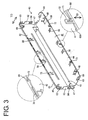
- the base shell 41 is so shaped as to be placeable on the substantially entire bottom surface of the housing 20, and an elevated portion 45 is formed with a step at the front end (back end in FIG. 3) of a flat main portion 44 excluding the opposite widthwise ends so as to be brought into contact with the slightly raised bottom surface of the housing 20 where the contact portion 22 is to be positioned on.
- Substantially gate-shaped inserting pieces 48 are formed preferably by cutting and bending at positions near the left and right or lateral ends of the rear end (front end in FIG. 1) of the base shell 41, whereas insertion grooves (not shown) vertically penetrating the placing portion 32 are formed at the lateral end positions of the placing portion 32 in the housing 20.
- the base shell 41 and the housing 20 are locked into each other by closely inserting the inserting pieces 48 of the base shell 41 into these insertion grooves.
- inserting pieces 49 are formed preferably by cutting and bending at positions near the left and right or lateral ends of a pivotal side of the lid shell 42, whereas insertion grooves 33 are formed at positions of the upper surface of the housing 20 outside the widthwise ends of the placing portion 32. With the lid shell 42 bent to become substantially parallel with the base shell 41, the inserting pieces 49 of the lid shell 42 are closely inserted into these insertion grooves 33 to lock the lid shell 42 and the housing 20 into each other.
- contact pieces 55 to be resiliently brought or bringable into contact with the bottom surface of the shorting element 18 of the above flat cable 10 are formed as shown preferably by cutting and bending at the rear end of the base shell 41, whereas windows 34 through which the contact pieces 55 are at least partly insertable are so formed in the bottom wall of the placing portion 32 as to substantially conform to the contact pieces 55.
- four contact pieces 56 to be resiliently brought or bringable into contact with the upper surface of the shorting element 18 are formed as shown preferably by cutting and bending at the pivotal end of the lid shell 42, whereas windows 38 through which the contact pieces 56 are at least partly insertable are so formed in the cover 35 as to substantially conform to the contact pieces 56.
- a locking plate 60 stands at each of the left and right or lateral edges of the base shell 41, and a locking piece 61 projecting obliquely downward or outwardly is formed preferably by cutting and bending at the outer surface of each locking plate 60.
- a locking projection 39 is formed at the front end of each of the left and right or lateral side surfaces of the housing 20.
- An engaging plate 62 stands at each of the left and right edges of the lid shell 42 and is formed with locking holes 63, 64 respectively engageable with the locking piece 61 and the locking projection 39 when the lid shell 42 is so bent as to become substantially parallel with the base shell 41.
- a finger placing portion 65 bulges out in widthwise direction at the rear end of each of the left and right ends of the housing 20, and a mount hole 66 into which the locking plate 60 is at least partly fittable vertically penetrates through each finger placing portion 65.
- a standing edge 68 is formed preferably over the substantially entire width at the rear end of the base shell 41, and a standing edge 69 is similarly formed at the pivotal end of the lid shell 42.
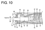
- the base and lid shells 41, 42 are enabled to have enhanced bending strengths with respect to thickness direction TD, TD' (vertical direction of the respective shells 41, 42) by providing these standing edges 68, 69.
- the leading end of the standing edge 68 of the base shell 41 serves as a wire pressing portion 68A, which is held substantially in contact with the shielded wires 11 after the base shell 41 is assembled with the housing 20.
- one or more, e.g. four wire pressing portions 70 are formed preferably near the substantially widthwise center as shown by bending portions extending from the leading end of the standing edge 69 of the lid shell 42 to extend toward the pivotal end (backward).
- the wire pressing portions 70 are held substantially in surface contact with the shielded wires 11 after the lid shell 42 is assembled with the housing 20. Since the wire pressing portions 68A, 70 are substantially opposed to each other, the shielded wires 11 are substantially tightly held between or sandwiched by the wire pressing portions 68A, 70 with the housing 20 and the shielding shell 40 assembled with each other.
- Three lock plates 72 each formed with a locking groove 71 stand at specified intervals at the standing edge 68 of the base shell 41 as shown, and hooks 73 engageable with the locking grooves 71 when the lid shell 42 is bent to become substantially parallel with the base shell 41 are so formed at the standing edge 69 of the lid shell 42 as to substantially conform to the lock plates 72.
- the terminal fittings 21 are at least partly mounted into the corresponding terminal insertion grooves 27 of the housing 20.
- the housing 20 is placed on the base shell 41 of the shielding shell 40 as indicated by an arrow (cover mounting direction CMD) in FIG. 2 while the inserting pieces 48 are at least partly inserted into the corresponding insertion holes (see FIG. 4).
- the end of the flat cable 10 is at least partly mounted into the mounting area 26 of the housing 20 from above as indicated by an arrow (flat cable mounting direction FCMD) in FIG. 4, whereby the shorting element 18 is positioned on the placing portion 32.
- FCMD flat cable mounting direction
- the cores 12 of the respective shielded wires 11 are pressed into the insulation-displacement grooves 24 of the insulation-displacement portions 23 of the corresponding terminal fittings 21 (see FIG. 6), thereby connecting the shielded wires 11 and the terminal fittings 21 with each other.
- each pair of front and rear pressing portions 37 provided on the rear surface of the cover 35 come to be located at the front and rear sides of the corresponding insulation-displacement portion 23, thereby pressing the core of the corresponding shielded wire 11 at the front and rear sides of its connected portion to keep the shielded wire 11 connected by insulation displacement.
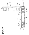
- the lid shell 42 is bent backward at specified positions of both coupling pieces 47 as indicated by an arrow in FIG. 7.
- the lid shell 42 is bent at 90°, at least part of the inserting pieces 49 are or can be substantially closely inserted into the insertion grooves 33 of the housing 20. Further, as shown in FIGS.
- the hooks 73 at the pivotal end of the lid shell 42 are at least partly resiliently fitted or inserted into the locking grooves 71 of the corresponding lock plates 72 of the base shell 41 at the rear end position of the housing 20, and the locking pieces 61 of the locking plates 60 and the locking projections 39 of the housing 20 are at least partly resiliently fitted or inserted into the locking holes 63, 64 of the corresponding engaging plates 62 at the lateral ends of the housing 20, whereby the base and lid shells 41, 42 are closed and locked into each other while tightly holding (or sandwiching) the housing 20 therebetween.
- the cover 35 is pressed by the lid shell 42 and the cores 12 of the respective shielded wires 11 are kept connected by insulation displacement as described above.
- the contact pieces 55, 56 of the base and lid shells 41, 42 are resiliently pressed against the outer surfaces of the shorting element 18 through the windows 34, 38 of the housing 20 and the cover 35 to establish electrical contacts.
- shielding effects such as removal of radiation noise can be obtained by the function of the shielding shell 40 provided to substantially surround the housing 20.
- the wire pressing portion 68A of the base shell 41 is held substantially in contact with the shielded wires 11 and the wire pressing portions 70 of the lid shell 42 are held substantially in surface contact with the shielded wires 11, with the result that the shielded wires 11 are tightly held between or sandwiched by the wire pressing portions 68A, 70.
- the base and lid shells 41, 42 are kept closed by a locking means (lock plates 72 and hooks 73) preferably provided in the substantially widthwise middle portion at the rear end position of the housing 20 or a position substantially opposed to the contact portion 22 or the elevated portion 45 or at a side where the flat cable 10 is to be drawn out of the connector.
- a locking means lock plates 72 and hooks 73
- the housing 20 and the shielding shell 40 are not resiliently deformed to open when the flat cable 10 is pulled in thickness direction TD, TD' or in a direction substantially normal to the plane of the flat cable 10 at that portion or to the longitudinal direction of the shielded wires 11, therefore preventing the flat cable 10 from being detached from the housing 20 or being cut.
- the wire pressing portions 70 are formed preferably by bending the end portions of the lid shell 42 to extend backward or outward or in a direction away from the elevated portion 45 or the coupling pieces 47 or in a direction substantially parallel to the shielded wires 11, a large contact surface with the shielded wires 11 can be ensured, thereby making it difficult to damage the shielded wires 11.
- a housing 20 holding an end of a flat cable 10 inside is covered by a base shell 41 and a lid shell 42.
- lock plates 72 provided on the base shell 41 and hooks 73 provided on the lid shell 42 are engaged with each other to keep the base and lid shells 41, 42 closed with respect to each other.
- the housing 20 and a shielding shell 40 are not resiliently deformed to open when the flat cable 10 is pulled in thickness direction. This prevents the flat cable 10 from being detached from the housing 20 or being cut.
Landscapes
- Details Of Connecting Devices For Male And Female Coupling (AREA)
- Coupling Device And Connection With Printed Circuit (AREA)
- Shielding Devices Or Components To Electric Or Magnetic Fields (AREA)
Abstract
Description
- 10
- flat cable
- 11
- shielded wire
- 12
- core
- 14
- shielding layer
- 18
- shorting element
- 20
- housing
- 21
- terminal fitting
- 35
- cover
- 40
- shielding shell
- 41
- base shell
- 42
- lid shell
- 57
- lock plate (locking means)
- 59
- hook (locking means)
- 70
- wire pressing portion
Claims (11)
- A connector for a plurality of wires (11), wherein at least a part of the wires (11) is shielded, in particular for a flat cable (10) in which the plurality of wires (11) are substantially juxtaposed, wherein at least a portion of connector cores (12) of the respective wires (11) are held substantially side by side along widthwise direction (WD) in a housing (20) and a shielding shell (41, 42) connectable with shielding layers (14) of the respective shielded wires (11) is so provided as to substantially cover the housing (20), wherein:the shielding shell (41, 42) is such that a lid shell (42) is openably and closably provided with respect to a base shell (41) to be mounted in or on the housing (20), anda locking means (72; 73) for keeping the base and lid shells (41, 42) substantially closed is provided at a rear end position of the housing (20) where the wires (11), in particular the flat cable (10) is to be drawn out between the base shell and the lid shell (41, 42).
- A connector for a flat cable according to claim 1, wherein the locking means (72; 73) for keeping the base and lid shells (41, 42) substantially closed is at least partly provided in a substantially widthwise middle portion at the rear end position of the housing (20).
- A connector for a flat cable according to one or more of the preceding claims, wherein the base and lid shells (42, 41) of the shielding shell (41, 42) are integrally or unitarily connected, preferably formed by pressing of one single conductive plate.
- A connector for a flat cable according to one or more of the preceding claims, wherein the shielding shell (41, 42) comprises at least one wire pressing portion (68A; 70; 76) for preventing the flat cable (10) from being displaced along thickness direction (TD; TD') by being held substantially in contact with the shielded wires (11) preferably at the rear end position of the housing (20).
- A connector for a flat cable according to one or more of the preceding claims, wherein at least one wire pressing portion (68A, 70; 70, 76) is provided at both base and lid shells (41, 42), and the shielded wires (11) are tightly held between these wire pressing portions (68A, 70; 70, 76).
- A connector for a flat cable according to claim 4 or 5, wherein the wire pressing portion (68A; 76) is formed by bending a rear end portion of at least one of the base and lid shells (41, 42) to extend backward or outwardly.
- A connector for a flat cable according to one or more of the preceding claims, wherein at least one of the base and lid shells (41, 42) comprises at least one strengthening portion (68; 69) for enhancing bending strengths thereof substantially with respect to thickness direction (TD; TD').
- A connector for a flat cable according to claim 7, wherein the locking means (72; 73) is at least partly provided on the strengthening portion (68; 69).
- A connector for a flat cable according to one or more of the preceding claims, wherein the locking means (72; 73) comprises at least one lock plate (72) which is to be inserted between adjacent shielded wires (11) upon closing of the base and lid shells (41, 42).
- A method of mounting a connector on a plurality of wires (11), wherein at least a part of the wires (11) is shielded, in particular for a flat cable (10), in which the plurality of wires (11) are substantially juxtaposed, wherein at least a portion of connector cores (12) of the respective wires (11) are held substantially side by side along widthwise direction (WD) in a housing (20) and a shielding shell (41, 42) connectable with shielding layers (14) of the respective shielded wires (11) is so provided as to substantially cover the housing (20), comprising the following steps:providing the shielding shell (41, 42) having a lid shell (42) being openably and closably provided with respect to a base shell (41)mounting the shielding shell (41, 42) on the housing (20), andkeeping the base and lid shells (41, 42) substantially closed by means of a locking means (72; 73) being provided at a rear end position of the housing (20) where the wires (11), in particular the flat cable (10), is drawn out between the base shell and the lid shell (41, 42).
- A method of assembling connector for a flat cable according to claim 10, wherein the locking means (72; 73) for keeping the base and lid shells (41, 42) substantially closed is provided in a substantially widthwise middle portion at the rear end position of the housing (20).
Applications Claiming Priority (2)
| Application Number | Priority Date | Filing Date | Title |
|---|---|---|---|
| JP2001381247A JP3887694B2 (en) | 2001-12-14 | 2001-12-14 | Flat cable connector |
| JP2001381247 | 2001-12-14 |
Publications (3)
| Publication Number | Publication Date |
|---|---|
| EP1320149A2 true EP1320149A2 (en) | 2003-06-18 |
| EP1320149A3 EP1320149A3 (en) | 2004-03-24 |
| EP1320149B1 EP1320149B1 (en) | 2006-11-08 |
Family
ID=19187309
Family Applications (1)
| Application Number | Title | Priority Date | Filing Date |
|---|---|---|---|
| EP02027139A Expired - Lifetime EP1320149B1 (en) | 2001-12-14 | 2002-12-04 | A connector for a flat cable and method of assembling it |
Country Status (6)
| Country | Link |
|---|---|
| US (1) | US6676444B2 (en) |
| EP (1) | EP1320149B1 (en) |
| JP (1) | JP3887694B2 (en) |
| CN (1) | CN1210845C (en) |
| DE (1) | DE60215906T2 (en) |
| TW (1) | TWI265658B (en) |
Cited By (6)
| Publication number | Priority date | Publication date | Assignee | Title |
|---|---|---|---|---|
| WO2005046001A1 (en) * | 2003-11-04 | 2005-05-19 | Molex Incorporated | Electrical connector assembly |
| EP2019452A1 (en) * | 2007-07-26 | 2009-01-28 | Japan Aviation Electronics Industry, Limited | Connector and electronic apparatus including the same |
| NL2001622C2 (en) * | 2007-05-28 | 2009-09-30 | Japan Aviation Electron | Connector, which is improved in connection reliability. |
| EP2037544A3 (en) * | 2007-09-06 | 2010-08-25 | J.S.T. Mfg. Co., Ltd. | Electric connector assembly kit and sheilded cable harness |
| EP1646114A3 (en) * | 2004-10-07 | 2011-03-09 | HONDA TSUSHIN KOGYO Co., Ltd. | Cable connector |
| EP1646113A3 (en) * | 2004-10-07 | 2011-03-09 | HONDA TSUSHIN KOGYO Co., Ltd. | Cable connector |
Families Citing this family (37)
| Publication number | Priority date | Publication date | Assignee | Title |
|---|---|---|---|---|
| US20040118976A1 (en) * | 2002-12-10 | 2004-06-24 | Joseph Albertelli | Secure composite cockpit door and method of manufacture |
| JP4098287B2 (en) * | 2003-10-03 | 2008-06-11 | 山一電機株式会社 | Flexible printed wiring board connector |
| US6755687B1 (en) * | 2003-10-15 | 2004-06-29 | Hon Hai Precision Ind. Co., Ltd. | Micro coaxial cable connector assembly with improved contacts |
| US6830478B1 (en) * | 2003-12-10 | 2004-12-14 | Hon Hai Precision Ind. Co., Ltd. | Micro coaxial connector assembly with latching means |
| JP2005243471A (en) * | 2004-02-27 | 2005-09-08 | D D K Ltd | Electric connector |
| JP4598431B2 (en) * | 2004-04-28 | 2010-12-15 | 株式会社フジクラ | Micro coaxial cable assembly and connector connection method of micro coaxial cable |
| JP2005322470A (en) * | 2004-05-07 | 2005-11-17 | Iriso Denshi Kogyo Kk | connector |
| US6994583B1 (en) * | 2004-07-21 | 2006-02-07 | L&K Precision Technology Co., Ltd. | Connector |
| JP2006066242A (en) * | 2004-08-27 | 2006-03-09 | Tyco Electronics Amp Kk | Electric connector for flat cable and shield member used for same |
| JP2006127943A (en) * | 2004-10-29 | 2006-05-18 | Tyco Electronics Amp Kk | Coupler for flat cable and electric connector assembly |
| US20060178048A1 (en) * | 2005-02-08 | 2006-08-10 | Ted Ju | Electrical connector and method for producing the same |
| JP4783096B2 (en) * | 2005-09-08 | 2011-09-28 | 山一電機株式会社 | Flexible conductor connector |
| JP2007280765A (en) * | 2006-04-06 | 2007-10-25 | Yokowo Co Ltd | Electrical connector |
| TW200832449A (en) * | 2006-10-23 | 2008-08-01 | Sumitomo Electric Industries | Coaxial cable and method for manufacturing the same |
| US8414961B1 (en) | 2006-12-13 | 2013-04-09 | Nanosolar, Inc. | Solution deposited transparent conductors |
| JP4879071B2 (en) * | 2007-04-02 | 2012-02-15 | タイコエレクトロニクスジャパン合同会社 | Connection structure of shielded wire |
| JP4900707B2 (en) * | 2007-04-26 | 2012-03-21 | 株式会社アイペックス | Electrical connector and manufacturing method thereof |
| JP5090055B2 (en) * | 2007-05-07 | 2012-12-05 | 日本航空電子工業株式会社 | connector |
| US7625231B2 (en) * | 2007-06-29 | 2009-12-01 | Yamaichi Electronics Co., Ltd. | Adaptor for cable connector |
| CN101350462B (en) * | 2007-07-21 | 2011-06-29 | 达昌电子科技(苏州)有限公司 | Structure for electric connector |
| JP2009193786A (en) * | 2008-02-13 | 2009-08-27 | Yamaichi Electronics Co Ltd | HDMI standard cable connector |
| JP4750811B2 (en) * | 2008-02-27 | 2011-08-17 | 京セラエルコ株式会社 | Cable connector |
| US8530262B2 (en) * | 2008-02-28 | 2013-09-10 | Nanosolar, Inc. | Roll-to-roll non-vacuum deposition of transparent conductive electrodes |
| JP2010056066A (en) * | 2008-07-29 | 2010-03-11 | Yamaichi Electronics Co Ltd | Cable connector |
| TW201103207A (en) * | 2009-07-15 | 2011-01-16 | Adv Flexible Circuits Co Ltd | Shielded insertion and connection structure of flat cable connector |
| JP5019079B2 (en) * | 2010-03-10 | 2012-09-05 | 第一精工株式会社 | Connector device |
| CN201797096U (en) * | 2010-04-19 | 2011-04-13 | 富士康(昆山)电脑接插件有限公司 | Cable connector component |
| JP5066243B2 (en) * | 2010-06-08 | 2012-11-07 | ヒロセ電機株式会社 | Electrical connector and method of connecting twisted pair cable and electrical connector |
| KR101139322B1 (en) | 2010-09-07 | 2012-04-26 | (주)우주일렉트로닉스 | Reinforcement Part For Flexible Cable |
| US8177564B1 (en) | 2010-12-03 | 2012-05-15 | Yamaichi Electronics Co., Ltd. | Receptacle connector and an electrical connector using the same |
| US8231407B1 (en) * | 2011-01-13 | 2012-07-31 | Hon Hai Precision Ind. Co., Ltd. | Cable assembly with improved grounding bar |
| JP5748335B2 (en) * | 2011-06-08 | 2015-07-15 | 日本航空電子工業株式会社 | connector |
| TWI458421B (en) * | 2011-12-21 | 2014-10-21 | Wistron Corp | Clamp mechanism |
| KR101920623B1 (en) | 2012-01-30 | 2018-11-21 | 삼성전자주식회사 | Signal cable, cable connector and signal cable connecting apparatus including the same |
| CN103247908A (en) * | 2012-02-06 | 2013-08-14 | 凡甲电子(苏州)有限公司 | Cable connector assembly |
| JP6002634B2 (en) * | 2013-06-14 | 2016-10-05 | 矢崎総業株式会社 | Flat cable connection structure |
| CN112531360A (en) * | 2020-12-16 | 2021-03-19 | 长春捷翼汽车零部件有限公司 | Terminal assembly and preparation method thereof |
Family Cites Families (11)
| Publication number | Priority date | Publication date | Assignee | Title |
|---|---|---|---|---|
| US4272148A (en) * | 1979-04-05 | 1981-06-09 | Hewlett-Packard Company | Shielded connector housing for use with a multiconductor shielded cable |
| US4457576A (en) * | 1982-12-17 | 1984-07-03 | Amp Incorporated | One piece metal shield for an electrical connector |
| US4534608A (en) * | 1984-05-21 | 1985-08-13 | Sperry Corporation | Shielded connector shell for flat cable |
| US4619487A (en) * | 1984-09-28 | 1986-10-28 | Thomas & Betts Corporation | Flat cable connector with grounding clip |
| US4772212A (en) * | 1987-05-20 | 1988-09-20 | Amp Incorporated | Electrical connector for shielded cables with shielded conductor pairs |
| NL9302005A (en) * | 1993-11-19 | 1995-06-16 | Framatome Connectors Belgium | Connector for shielded cables. |
| US5605469A (en) * | 1995-01-05 | 1997-02-25 | Thomas & Betts Corporation | Electrical connector having an improved conductor holding block and conductor shield |
| TW335229U (en) * | 1997-03-21 | 1998-06-21 | Hon Hai Prec Ind Co Ltd | Plug connector |
| US5980308A (en) * | 1998-05-13 | 1999-11-09 | Hu; Yu-Tung | Female socket of a connector |
| JP3383222B2 (en) | 1998-08-28 | 2003-03-04 | ケル株式会社 | Connector for cable connection |
| TW435873U (en) * | 1998-12-08 | 2001-05-16 | Hon Hai Prec Ind Co Ltd | Cable connector assembly |
-
2001
- 2001-12-14 JP JP2001381247A patent/JP3887694B2/en not_active Expired - Fee Related
-
2002
- 2002-12-02 US US10/307,825 patent/US6676444B2/en not_active Expired - Fee Related
- 2002-12-04 EP EP02027139A patent/EP1320149B1/en not_active Expired - Lifetime
- 2002-12-04 DE DE60215906T patent/DE60215906T2/en not_active Expired - Fee Related
- 2002-12-13 CN CNB021560625A patent/CN1210845C/en not_active Expired - Fee Related
- 2002-12-13 TW TW091136157A patent/TWI265658B/en not_active IP Right Cessation
Cited By (10)
| Publication number | Priority date | Publication date | Assignee | Title |
|---|---|---|---|---|
| WO2005046001A1 (en) * | 2003-11-04 | 2005-05-19 | Molex Incorporated | Electrical connector assembly |
| US7040917B2 (en) | 2003-11-04 | 2006-05-09 | Molex Incorporated | Electrical connector assembly |
| KR100797345B1 (en) * | 2003-11-04 | 2008-01-22 | 몰렉스 인코포레이티드 | Electrical connector assembly |
| EP1646114A3 (en) * | 2004-10-07 | 2011-03-09 | HONDA TSUSHIN KOGYO Co., Ltd. | Cable connector |
| EP1646113A3 (en) * | 2004-10-07 | 2011-03-09 | HONDA TSUSHIN KOGYO Co., Ltd. | Cable connector |
| NL2001622C2 (en) * | 2007-05-28 | 2009-09-30 | Japan Aviation Electron | Connector, which is improved in connection reliability. |
| US7674134B2 (en) | 2007-05-28 | 2010-03-09 | Japan Aviation Electronics Industry, Limited | Shielded connector |
| EP2019452A1 (en) * | 2007-07-26 | 2009-01-28 | Japan Aviation Electronics Industry, Limited | Connector and electronic apparatus including the same |
| US7597584B2 (en) | 2007-07-26 | 2009-10-06 | Japan Aviation Electronics Industry, Limited | Connector and electronic apparatus including the same |
| EP2037544A3 (en) * | 2007-09-06 | 2010-08-25 | J.S.T. Mfg. Co., Ltd. | Electric connector assembly kit and sheilded cable harness |
Also Published As
| Publication number | Publication date |
|---|---|
| JP2003187901A (en) | 2003-07-04 |
| DE60215906T2 (en) | 2007-06-14 |
| JP3887694B2 (en) | 2007-02-28 |
| EP1320149B1 (en) | 2006-11-08 |
| CN1427507A (en) | 2003-07-02 |
| DE60215906D1 (en) | 2006-12-21 |
| US6676444B2 (en) | 2004-01-13 |
| US20030114046A1 (en) | 2003-06-19 |
| TWI265658B (en) | 2006-11-01 |
| EP1320149A3 (en) | 2004-03-24 |
| TW200301027A (en) | 2003-06-16 |
| CN1210845C (en) | 2005-07-13 |
Similar Documents
| Publication | Publication Date | Title |
|---|---|---|
| EP1320149B1 (en) | A connector for a flat cable and method of assembling it | |
| TWI470878B (en) | Connector assembly | |
| US6840798B2 (en) | Shielding connector, a shielding connector system, a terminal fitting and use thereof | |
| US7134900B2 (en) | Electrical connector assembly with multi-function latching member | |
| US6210230B1 (en) | Cable connector | |
| JP2018063793A (en) | Connector structure | |
| US6997749B1 (en) | Shield connector | |
| JP2924857B2 (en) | Electrical connector | |
| US9231319B2 (en) | Electrical connector assembly with a supporting plate and assembly method of the same | |
| JP3887697B2 (en) | Flat cable connector | |
| US20070010124A1 (en) | Cable assembly with flat flexible cable | |
| US6142821A (en) | Electrical connector assembly with guiding device | |
| US6957975B2 (en) | Plug connector housing with locking mechanism and plug connector having such housing | |
| CN100505434C (en) | Multiconnection plug connector and longitudinally laminated and laterally laminated socket connectors | |
| US20040102083A1 (en) | Receptacle connector with latch arms and plug connector to be connected thereto | |
| US6780063B2 (en) | Wire connected modular jack and assembling method | |
| JP2002373739A (en) | Flat cable connector | |
| US7077690B2 (en) | Electrical connector with improved slider member | |
| KR100549788B1 (en) | Automotive Connector Assemblies | |
| JP3680767B2 (en) | Flat cable connector | |
| JP4228978B2 (en) | connector | |
| JP2000299167A (en) | Electrical connector | |
| JP4602050B2 (en) | Multi-connection type header connector and vertical socket connector and horizontal socket connector connected to this | |
| JP2001028282A (en) | Flat cable connector | |
| US7086883B2 (en) | Electrical connector assembly with two dielectric housings arrangeable at different angles |
Legal Events
| Date | Code | Title | Description |
|---|---|---|---|
| PUAI | Public reference made under article 153(3) epc to a published international application that has entered the european phase |
Free format text: ORIGINAL CODE: 0009012 |
|
| AK | Designated contracting states |
Designated state(s): AT BE BG CH CY CZ DE DK EE ES FI FR GB GR IE IT LI LU MC NL PT SE SI SK TR |
|
| AX | Request for extension of the european patent |
Extension state: AL LT LV MK RO |
|
| PUAL | Search report despatched |
Free format text: ORIGINAL CODE: 0009013 |
|
| AK | Designated contracting states |
Kind code of ref document: A3 Designated state(s): AT BE BG CH CY CZ DE DK EE ES FI FR GB GR IE IT LI LU MC NL PT SE SI SK TR |
|
| AX | Request for extension of the european patent |
Extension state: AL LT LV MK RO |
|
| RIC1 | Information provided on ipc code assigned before grant |
Ipc: 7H 01R 13/58 B Ipc: 7H 01R 13/658 B Ipc: 7H 01R 12/24 A |
|
| 17P | Request for examination filed |
Effective date: 20040422 |
|
| 17Q | First examination report despatched |
Effective date: 20040623 |
|
| AKX | Designation fees paid |
Designated state(s): DE FR GB |
|
| GRAP | Despatch of communication of intention to grant a patent |
Free format text: ORIGINAL CODE: EPIDOSNIGR1 |
|
| GRAS | Grant fee paid |
Free format text: ORIGINAL CODE: EPIDOSNIGR3 |
|
| GRAA | (expected) grant |
Free format text: ORIGINAL CODE: 0009210 |
|
| AK | Designated contracting states |
Kind code of ref document: B1 Designated state(s): DE FR GB |
|
| REG | Reference to a national code |
Ref country code: GB Ref legal event code: FG4D |
|
| REF | Corresponds to: |
Ref document number: 60215906 Country of ref document: DE Date of ref document: 20061221 Kind code of ref document: P |
|
| ET | Fr: translation filed | ||
| PLBE | No opposition filed within time limit |
Free format text: ORIGINAL CODE: 0009261 |
|
| STAA | Information on the status of an ep patent application or granted ep patent |
Free format text: STATUS: NO OPPOSITION FILED WITHIN TIME LIMIT |
|
| 26N | No opposition filed |
Effective date: 20070809 |
|
| GBPC | Gb: european patent ceased through non-payment of renewal fee |
Effective date: 20070208 |
|
| PG25 | Lapsed in a contracting state [announced via postgrant information from national office to epo] |
Ref country code: GB Free format text: LAPSE BECAUSE OF NON-PAYMENT OF DUE FEES Effective date: 20070208 |
|
| PGFP | Annual fee paid to national office [announced via postgrant information from national office to epo] |
Ref country code: FR Payment date: 20071210 Year of fee payment: 6 |
|
| PGFP | Annual fee paid to national office [announced via postgrant information from national office to epo] |
Ref country code: DE Payment date: 20071129 Year of fee payment: 6 |
|
| REG | Reference to a national code |
Ref country code: FR Ref legal event code: ST Effective date: 20090831 |
|
| PG25 | Lapsed in a contracting state [announced via postgrant information from national office to epo] |
Ref country code: DE Free format text: LAPSE BECAUSE OF NON-PAYMENT OF DUE FEES Effective date: 20090701 |
|
| PG25 | Lapsed in a contracting state [announced via postgrant information from national office to epo] |
Ref country code: FR Free format text: LAPSE BECAUSE OF NON-PAYMENT OF DUE FEES Effective date: 20081231 |