EP1320087A2 - Synthesis of an excitment signal for use in a comfort noise generator - Google Patents
Synthesis of an excitment signal for use in a comfort noise generator Download PDFInfo
- Publication number
- EP1320087A2 EP1320087A2 EP03005562A EP03005562A EP1320087A2 EP 1320087 A2 EP1320087 A2 EP 1320087A2 EP 03005562 A EP03005562 A EP 03005562A EP 03005562 A EP03005562 A EP 03005562A EP 1320087 A2 EP1320087 A2 EP 1320087A2
- Authority
- EP
- European Patent Office
- Prior art keywords
- frame
- excitation
- signal
- samples
- speech
- Prior art date
- Legal status (The legal status is an assumption and is not a legal conclusion. Google has not performed a legal analysis and makes no representation as to the accuracy of the status listed.)
- Granted
Links
Images

Classifications
-
- G—PHYSICS
- G10—MUSICAL INSTRUMENTS; ACOUSTICS
- G10L—SPEECH ANALYSIS OR SYNTHESIS; SPEECH RECOGNITION; SPEECH OR VOICE PROCESSING; SPEECH OR AUDIO CODING OR DECODING
- G10L19/00—Speech or audio signals analysis-synthesis techniques for redundancy reduction, e.g. in vocoders; Coding or decoding of speech or audio signals, using source filter models or psychoacoustic analysis
- G10L19/012—Comfort noise or silence coding
-
- H—ELECTRICITY
- H04—ELECTRIC COMMUNICATION TECHNIQUE
- H04J—MULTIPLEX COMMUNICATION
- H04J3/00—Time-division multiplex systems
- H04J3/17—Time-division multiplex systems in which the transmission channel allotted to a first user may be taken away and re-allotted to a second user if the first user becomes inactive, e.g. TASI
- H04J3/175—Speech activity or inactivity detectors
-
- G—PHYSICS
- G10—MUSICAL INSTRUMENTS; ACOUSTICS
- G10L—SPEECH ANALYSIS OR SYNTHESIS; SPEECH RECOGNITION; SPEECH OR VOICE PROCESSING; SPEECH OR AUDIO CODING OR DECODING
- G10L25/00—Speech or voice analysis techniques not restricted to a single one of groups G10L15/00 - G10L21/00
- G10L25/03—Speech or voice analysis techniques not restricted to a single one of groups G10L15/00 - G10L21/00 characterised by the type of extracted parameters
- G10L25/18—Speech or voice analysis techniques not restricted to a single one of groups G10L15/00 - G10L21/00 characterised by the type of extracted parameters the extracted parameters being spectral information of each sub-band
Definitions
- the invention relates to the synthesis of a signal. excitation used in a comfort noise generator, in a digital speech transmission system discontinuous.
- transmission systems discontinuous speech include a voice activity module allowing to deliver information relating to the presence or the absence of the voice signal.
- the speech signal delivered by the aforementioned systems, thus includes the voice signal proper aforementioned followed and / or preceded by rests.
- the system transmission is controlled so as to decrease the speed signal transmitted, or simply cut the transmission.
- the amplitude parameters of the excitation blocks and Log Area Ratios (LAR) from the LPC analysis of the encoder provide information on the level or amplitude and the envelope of the frequency spectrum (LAR) of the ambient noise.
- the comfort noise generator averages these parameters over a determined number of consecutive frames, quantifies them according to the quantization procedure used by the speech coder and generates a silence description frame, Silence Registration Descriptor (SID) frame. Anglo-Saxon language). Such a frame is generated at the end of an active period and every 480 ms of each inactive period.
- the SID frames are coded, provided with a SID code word ensuring the marking of these frames, then transmitted for reception by a decoder.
- the comfort noise is synthesized at the decoder by randomly drawing the codes of the excitation parameters, zeroing the gain code of the long-term predictor, replacing the codes corresponding to the LPC analysis and to the amplitude of the blocks d excitation by the SID frame codes.
- the decoding of the inactive frames is then carried out like that of the speech frames.
- the comfort noise generator modules are external to the speech coder and decoder, which has the advantage of greater system modularity at the cost of increasing the complexity of processing inactive frames: l
- the development of SID frames at the coder and the random formation of excitation codes are added to the normal processing of speech frames.
- the local decoder of the speech coder, on transmission, and the remote decoder, on reception, are no longer synchronous after an inactive period, because the operation of the coder is independent of the system.
- the European half-speed radiomobile system also has a comfort noise generator with a structure similar to that of the full-speed system, see ETSI Recommendation GSM 06.22 and GSM 06.20. Equivalent to the process implemented by the CNG generator of the full-rate system, the CNG generator uses the autocorrelations of the speech signal, input signal, on 8 successive frames to evaluate the spectrum of ambient noise.
- the speech coder has been adapted to operate during inactive periods, synchronously with the remote decoder, the random generator being reinitialized at each start of the inactive zone.
- the excitation signal can be carried out by random drawing of samples.
- the drawing of N excitation samples of a frame can be carried out for example in the interval [-g t ⁇ 3 , g t ⁇ 3 ] by means of a random generator of uniform law, where g t is the gain of the current frame.
- a more advantageous variant consists in randomly drawing the codes of the parameters characterizing the excitation signal and in providing these codes directly to the decoder.
- This method has the advantage of allowing an autonomous implantation of the comfort noise generator at the decoder, and avoids possible discontinuities in the excitation signal at the time of switching between the active frames and the comfort noise.
- the excitation parameter codes must be adjusted so that the energy of the excitation decoded for the current frame corresponds to the desired energy, namely Ng t 2 , where g t 2 corresponds to the average energy per sample. and Ng t 2 denotes the energy to be obtained for the N constituent samples of this frame.
- An object of the present invention is to achieve a level of synthesis quality comparable to that of the systems at high speed while allowing transmission rates comparable to those of systems with strong flow reduction.
- Another object of the present invention is further the creation of a good quality comfort noise, representative of the ambient environment while minimizing the volume and data rate to be transmitted to ensure this creation.
- the present invention relates to a process for the synthesis of excitation signal advantageously used in a generator comfort noise in a digital transmission system of discontinuous speech comprising a type speech coder predictive, from a determined number of samples excitement from past frames and data LTP long term prediction delivered by this speech coder.
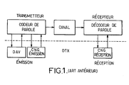
- a creation of a classic comfort noise in a digital speech transmission includes, on transmission, in addition to a speech coder, a voice activity detector, noted DAV, and a CNG generator.
- the set allows, transmission, periodically transmit frames descriptive of silence or SID frames, according to one of methods previously described in the description on a transmission channel proper.
- a speech decoder predictive type when the speech coder used at the emission is also a predictive type coder, allows decoding speech signals when these are transmitted, respectively SID frames, and creation thanks to a CNG generator upon receiving a noise corresponding comfort.
- the digital speech transmission is ensured in discontinuous, this transmission therefore consisting of successive active periods during which frames coded speech signal are transmitted, interspersed with inactive periods during which no signal frame speech is not transmitted.
- the respective duration of these periods is arbitrary due to the asynchronous nature of the transmission.
- the process for creating a comfort noise is set works on the broadcast, preferably following the detection of a inactive period.
- Detection of an inactive period can for example be made from the signal delivered by a voice activity detector DAV, at which a time delay is applied, to ensure the effective passage in period inactive.
- This time delay can also be adjusted to take into account the duration of the detection period, shown in Figure 2a, to ensure implementation correct creation of comfort noise.
- the detection period is represented by a interval delimited by dotted lines according to the period active considered.
- This description frame of silence consists of a set of coded parameters descriptions of comfort noise. This description frame of silence is in fact the first inactive frame of the inactive period following the active period and the period of previously cited detection.
- this reduces the flow of transmission of comfort noise to that of only description of silence whose frequency spectrum is different than the silence description frame previous.
- the spectrum of reference frequencies can be formed from the frequency spectrum of the ambient noise obtained during the creation of each silence description frame. So, we advantageously provides for a step 103 of memorizing the ambient noise to obtain the frequency spectrum for each SID frame.
- this reference spectrum Sfr is either estimated or advantageously directly obtained from the spectrum of reference calculated to design the SID frame, and stored for processing subsequent inactive frames. This spectrum of reference is refreshed with each new frame of description of silence issued, using the same method as that used to initialize it to the first SID frame of a inactive period.
- the estimated frequency spectrum calculated for each SID frame and which can also constitute the spectrum of reference frequencies can be performed according to the mode preferential realization which will now be described in link with Figure 2b.
- each silence description frame SID frame
- each SID frame we establishes each silence description frame, SID frame, according to a particular process allowing in a way adapt each SID frame to changes in ambient noise, and therefore to take into account, for the creation of the spectrum of the SID frame, some specific elements of this evolution.
- the process of establishing each description frame of silence can understand the step of determining the average frequency spectrum of successive inactive frames to establish a past average frequency spectrum, denoted SFmp, this step bearing the reference 1041 in FIG. 2b.
- the aforementioned step 1042 consists of an identity test of the past average frequency spectrum and the spectrum of frequencies of the current inactive frame symbolized by the relation (2): SFc ⁇ SFmp.
- the identity criterion does not correspond not a strict identity of frequency spectra compared, a law or criterion of correspondence which can be established. This step actually makes it possible to measure local stationarity of the frequency spectrum.
- step 1043 On identity criteria of frequency spectra above, we select in step 1043 as a frame of description of silence SID the average spectrum past SFmp, and, on lack of identity of the frequency spectra previously mentioned, in a step 1044, the spectrum of frequencies of the corresponding current inactive frame.
- This operating mode then allows, in a particularly advantageous, to estimate the spectrum of silence of any current inactive frame depending on whether such a frame belongs either to a locally stationary spectral zone, or to a non-stationary spectral zone.
- the number n of inactive frames successive on which the calculation of the past average spectrum is arbitrary, this can for example be taken equal to so as to get a corresponding time interval of around 100 ms. It is further indicated that the weft of description of SID silence thus constituted is subject to quantification prior to its transmission.
- this embodiment is well suited when the speech coder and speech decoder used on transmission, respectively on reception, are of the type predictive.
- the decoded signal is obtained by filtering an excitation signal, this signal coming from innovation dictionaries more than one long-term excitation, by an LPC synthesis filter hereinafter referred to as the LPC filter.
- the parameters representing the ambient noise spectrum are then given by the coefficients the LPC filter, for the spectrum envelope, and by the energy of the excitation signal for the spectrum level supra.
- step 100 ' we compare the LPC filter of the frame current, noted Fc, by storing in 101 'the current filter Fc, then comparison at 102 'of the current filter Fc to the filter of reference Fr obtained and memorized during the previous one SID frame according to step 103 '.
- Step 100' Absence of identity of the filters mentioned above in the step 102 ', a new SID frame is transmitted in step 100'.
- Steps 100 ', 101', 102 'and 103' are substantially unchanged from steps 100, 101, 102 and 103 of the Figure 2a.
- this comparison may consist of a comparison of the difference of these energies compared to a threshold value E 0 , a new SID frame is created and transmitted by returning to step 100 'previously described. If, on the contrary, in response to the test of step 104'c, the difference between the aforementioned excitation energies is not significant, we delay any transmission of a frame in step 104'd analogous to step 104d of FIG. 2a.
- the aforementioned distances can consist of the distance from ITAKURA-SAITO, that of the maximum likelihood, or Euclidean distances calculated on parameters derived from LPC coefficients, pairs of spectral lines, or log area ratios, for example.
- the quantifier used is that used to calculate the energy encoded in the SID frames.
- the aforementioned device comprises, associated with a speech coder labeled 1, module 2 of detection of the end of each active period during a detection period following each active period.
- module 2 can be constituted by a classic type voice activity detector, interconnected speech coder 1 and delivering a logic signal, noted VADin representative of the presence of a period activity during which coded speech frames are transmitted, respectively from a period of absence from activity during which silence description frames must be transmitted, or on the contrary no frame is transmitted.
- a CNG generator bearing the reference 3 is associated, of a hand, to speech coder 1, and, on the other hand, to module 2 voice activity.
- a multiplexer 4 receives, on the one hand, the coded speech frames delivered by the speech coder 1 and the signals constituted by the description frame of silence or coded SID frames delivered by the generator CNG 3, respectively a signal representative of the type of transmission to be provided by this same CNG 3 generator, and bearing the reference VADout.
- the CNG 3 generator includes a module 3a for creation and conditional transmission, during periods of inactivity, a description frame of silence, consisting of a set of coded parameters descriptions of comfort noise, a module 3b for analysis and memorizing the frequency spectrum of any inactive frame current, a 3c spectrum comparison module frequencies of the current inactive frame at a spectrum of reference frequencies delivering a control signal determined on criteria of identity and lack of identity of frequency spectra of the current and reference frame, a 3d module for estimating the type of transmission for current frame delivering for any frame a VADout signal to 3 levels coding the information respectively active frame, frame not transmitted and silence description frame.
- This 3d module receives, on the one hand, the signal produced by the voice activity detection module 2, on the other hand, the comparison signal produced by the module 3c as well as indicated below.
- the 3d module retransmits this information in the VADout signal. Otherwise, when the current frame is the first frame inactive during the active period, the 3d module assigns to signal VADout the value corresponding to the frame information description of silence, thereby authorizing transmission of a new silence description frame.
- module 3c compares the frequency spectrum of the current frame with the frequency spectrum of reference, and on criteria of identity and absence of identity of these spectra, delivers the representative CMP signal frame information not transmitted and frame respectively description of silence.
- the 3d module to from the CMP signal, ensures coding in the VADout signal transmission information to postpone any transmission during the identity of the spectra of frequencies of the current and reference frame and of transmit a new description frame of silence during the absence of identity of these specters.
- Modules 3a and 3b exchange with the encoder speech a number of encoder management signals from speech, noted Sg: as input, these modules receive the data allowing the evaluation of the frequency spectra of the current frame, module 3b, and a number of frames prior to the current frame, module 3a, at output, according to the needs of the speech coder, module 3a if necessary, communicates the signals to the speech coder to update its memories, to avoid a desynchronization with the speech decoder located at the reception.
- the module 3a also receives the frequency spectrum of the current frame generated by the module 3b, signal SF c .
- the speech encoder 1 is a speech encoder predictive, comprising for each speech frame a module LPC analysis order of analysis M, the order of analysis being defined from the number of coefficients of the LPC filter, producing in particular the (M + 1) function coefficients autocorrelation of the speech signal, the M parameters representative of the LPC filter of the frame, noted Lpc, being coded using a predictive coding method using for each frame the Lpc parameters of the previous frames.
- Predictive coding of Lpc parameters is not necessary for the operation of this device, but present however, repercussions on the design of the latter. In the case of an encoder not using predictive coding Lpc parameters, the device can easily be simplified.
- the speech coder 1 develops and stores for example using analysis-by-synthesis techniques a signal of excitation, noted in the following Exc, identical to that calculated at the decoder to excite the LPC synthesis filter.
- Figure 3a shows the general architecture of the device previously shown in Figure 2e.
- the generator CNG 3 receives, from speech coder 1 of predictive type, the autocorrelation function Acf of the speech signal, the Lpc parameters of the previous frame, and, if applicable, a number of samples of the excitation signal Exc (n) partially constituting the excitation signal Exc, originating previous frames. It is indicated that the introduction of aforementioned samples is conditional on use, for the synthesis of comfort noise, long excitement predictive coder term.
- the generator CNG 3 includes a module 30 for calculating the parameters relating to the current frame Pc, receiving the autocorrelation function signal of the speech signal Acf and producing the signals as an output. corresponding to the parameters of the current frame Pc. These parameters include the current filter Fc and the current excitation energy E c .
- the CNG 3 generator also includes, as well as shown in Figure 3b, a decision module 31 transmission of a coded speech frame, or a frame of description of silence, SID frame, or suspension of transmission, receiving the VADin voice activity signal and parameters relating to the current frame Pc and the parameters reference Pr delivered by a module 32, which will be described later.
- the CNG 3 generator also includes a module 32 conditionally calculating the incoming signal VADout signals corresponding to the calculated reference parameters Pr at each SID frame. These parameters include the reference Fr and the reference excitation energy Er. This module receives as input the autocorrelation signals Acf and the parameters of the current frame Pc.
- the CNG generator 3 then includes a module 33 SID silence description frame generator in form coded, receiving the VADout transmission type signal, and the signals corresponding to the reference parameters Pr, and conditionally delivering a description frame signal coded silence.
- the CNG generator 3 then comprises a module 34 generator of an excitation signal Exc, receiving the signal VADout transmission type, the signals corresponding to reference parameters Pr and, as will be seen below, a number of samples passed Signal Excpas excitation provided by the speech coder.
- This module conditionally issues a signal VADout, a signal excitation for the current frame Exc.
- the CNG 3 generator finally includes a module 35 generator of a descriptive signal of the filtering parameters Lpc refreshed, receiving transmission type signal VADout, and the signals corresponding to the parameters of reference Pr, the descriptive signal of the Lpc parameters of the previous frames delivered by the speech coder 1, and updating, conditionally on VADout, this signal for the current frame, Lpcr.
- the CNG 3 generator module output, for each frame, the three-way transmission type signal VADout levels previously mentioned.
- the CNG 3 generator also produces the insertion parameters silence codes, constituting SID frames.
- the CNG 3 generator module delivers plus, if necessary, a frame excitation signal current Exc, and the signal Lpcr of the parameters Lpc updated.
- the module 33 encodes the parameters of the SID frame.
- the coefficients a t (i) denote the coefficients of the LPC filter calculated from the autocorrelation coefficients of the autocorrelation signal Acf previously mentioned, i denoting the index of each coefficient.
- This filter is compared with a transfer function reference filter A ref (z) stored during the previous SID frame, as described above. This comparison can be made using the Itakura-Saito distance mentioned above. This distance is compared with a threshold value, which avoids the need to calculate a logarithm and eliminates any division operation, the comparison with the threshold value being carried out according to relation (4) below.
- Err t denotes the residual energy LPC for the current frame, sum of the squares of the residual signal LPC, this residual energy can be obtained in the filter calculation procedure by the Levinson / Durbin method
- R Aref denotes a function derived from the autocorrelation of the coefficients of the reference filter A ref (z) verifying the relation (5):
- an operation for estimating the energy of the excitation of the current frame E t is carried out on the basis of the residual energy LPC Err t .
- the residual energy LPC Err t is multiplied by a factor noted CE estimated by learning.
- CE estimated by learning.
- the aforementioned number m of frames is initialized to 1 at the start of each inactive zone, then it can be incremented at each frame up to a maximum value determined.
- the aforementioned operation 1023 is then followed by an operation 1024 consisting in comparing the LPC filter of the current frame and the reference filter A ref (z) as mentioned previously.
- the signal VADout is positioned at 2 in step 1027 thus authorizing the transmission of an SID frame.
- a test 1025 is then carried out, this test 1025 consisting of a test on the quantized values of the average of the energies obtained in relation (6) above, the quantization index for the current frame i ( t) being compared with that of the reference frame obtained during the previous SID frame, denoted i ref according to relation (7):
- the current frame is defined as a frame of silence not transmitted 1026, the signal VADout being equal to 0.
- a past average LPC filter whose transfer function is denoted A past (z) is evaluated in step 1100 according to the relation (8):
- This filter is calculated from the sum of the signal autocorrelations, denoted Acf previously, of the p 1 frames preceding the current frame.
- An autocorrelation calculation R Apast of the coefficients of this filter is then carried out in accordance with the method given by the above-mentioned relation (5).
- a local stationarity measurement test is carried out in 1101 in a similar manner to the test 1024 described in relation to FIG. 3c, in accordance with the relation (2) previously mentioned.
- the threshold value for test 1101 is a particular value equal to threshold.
- a quantification step 1104 is then carried out on the parameters representing the selected reference filter previously 1104, the quantization operation being performed according to the procedure used by the coder, the code thus obtained being inserted into the coded SID frame.
- a step 1105 the excitation energy already calculated and quantified in 1023 i (t) is inserted into the corresponding SID frame and stored as reference energy i ref .
- i ref denoting the quantification index of the reference energy
- ⁇ is a real coefficient between 0 and 1.
- a simple method of synthesizing this excitation signal can consist of randomly drawing a density signal from uniform probability and given amplitude, calculated from of the energy transmitted for example.
- Another method may be to synthesize by random draw an excitation of the same type as that used by the speech coder, the advantage of this second method residing in the possibility of carrying out a module external to the decoder in the reception part.
- the risk of breaking with the previous decoded frames is weaker because the excitement doesn't suddenly change type.
- the speech coder communicates to the CNG 3 module a certain number of samples excitation signal Excpas from past frames, signal shown in dotted lines in Figure 3b.
- the frame of N samples is divided into N / L blocks of L samples on which the excitation parameters are calculated and coded. according to the needs of the speech coder, these blocks can be subdivided, the calculation period of the excitation codes at long term does not necessarily correspond to that of innovation.
- step 1201 makes it possible to initialize at 0 the counting variable j relating to the completeness of a block of N / L samples.
- the codes of the parameters of the long-term excitation are drawn randomly, in a step 1202.
- a constraint is preferable on the code of the gain of the long-term excitation to limit the energy of it.
- the innovation excitement signal is then obtained, in a step 1203, by random drawing of the code of the innovation waveform.
- We then obtain the L waveform samples u (n), with n jL + k, k varying from 0 to L-1, on the block.
- Step 1204 makes it possible to search for the quantification index ind of the gain in the innovation excitation, and therefore, by the dequantification operation, the associated gain ⁇ .
- the excitation e LTP (n) is obtained by randomly drawing the codes representing the LTP delay, for a gain equal to 1.
- the relation (10) is then modified to (11): the dequantized gains ⁇ 1 , ⁇ 2 being selected jointly by exploring the dictionary of the vector quantizer.
- Step 1204 is followed by a step 1205 where the excitation signal Exc is updated by the calculation of Exc for the samples of the current block.
- the device on reception includes a module 5 comfort noise decoding or, more particularly, in each successive silence description frame, the set of coded parameters describing this noise of comfort.
- Module 5 is associated with the speech decoder properly says and receives frame type information current processed by this module 5, information noted VAD, this information reproducing the signal information at 3 VADout levels generated on transmission, as well as of course silence description frames or coded SID frames. he additionally receives from the speech decoder a management signal Sg ensuring synchronization with the decoder.
- Module 5 allows to generate parameters descriptions of the comfort noise PBc relating to the frame common.
- the speech signal decoder receives, on the one hand, the coded speech frames, and, on the other hand, the signal description of the PBc comfort noise parameters relating to the current frame. It synthesizes a signal of synthesized speech, designated by the term decoded signal, on the above figure.
- the decoding module 5 comprises, at least, a demultiplexer 50 receiving the transmitted coded silence description frame signal and delivering a coded signal describing the LPC filtering parameters, this signal relating to the current frame being denoted Lpc c in the figure 4b, as well as a quantized gain index signal i ref , describing the level of the synthesized excitation signal. These parameters are used until the next SID frame.
- a dequantizer module 51 which receives the aforementioned quantized gain index signal and delivers a dequantized gain signal, denoted g ref .
- a calculation module 52 is provided, which receives the coded descriptive signal of the LPC filtering parameters relating to the current frame, denoted Lpc c , the descriptive signal of the LPC filtering parameters relating to at least the previous frame, denoted Lpc, and l frame type information, denoted VAD. The calculation module 52 then delivers the updated LPC signal with the LPC parameters of the current frame.
- an excitation generator module 53 which receives the dequantized gain signal g ref , where appropriate the past excitation signal and the frame type information VAD, and delivers the excitation signal relating to the current frame Exc.
- the decoder module 5 only works when the frames are not active.
- the decoding module 5 produces for each frame inactivates the N new signal samples Exc excitation and new LPC parameters after dequantification, noted Lpc.
- the speech decoder uses this data to synthesize inactive frames.
- the calculation module 52 calculates a new set of LPC parameters by quantifying and dequantizing Lpc ref using the past parameters Lpc provided by the decoder, the dequantized gain g ref not changing and the gain relative to the current frame g t being updated according to the relationship previously mentioned in the description.
- module 53 calculates the new excitation Exc relative to the current frame and transmits it to the speech decoder, which synthesizes the signal decoded inactive frames.
- noise decoder module 5 of comfort can be made completely autonomous and implanted external to the decoder.
- the processes used are the same by transfer of certain basic functions of the decoder in this module.
- correction factor C E and the previous values were adapted for the ITU standard G 723 predictive coder, a predictive coder for PSTN video telephony.
- the invention in the context described above, allows the implementation and creation of good noise quality, which is synthesized even when the average rate of transmission is weak, at the cost of a complexity of moderate calculation.
Abstract
Description
L'invention concerne la synthèse d'un signal d'excitation utilisé dans un générateur de bruit de confort, dans un système de transmission numérique de parole discontinue.The invention relates to the synthesis of a signal. excitation used in a comfort noise generator, in a digital speech transmission system discontinuous.
De manière générale, les systèmes de transmission de parole discontinue incluent un module d'activité vocale permettant de délivrer une information relative à la présence ou à l'absence du signal vocal. Le signal de parole, délivré par les systèmes précités, comprend ainsi le signal vocal proprement dit précité suivi et/ou précédé par des silences. Lorsqu'un silence ou inactivité est détecté, le système de transmission est commandé de façon, soit à diminuer le débit de signal transmis, soit à couper simplement la transmission.Generally speaking, transmission systems discontinuous speech include a voice activity module allowing to deliver information relating to the presence or the absence of the voice signal. The speech signal, delivered by the aforementioned systems, thus includes the voice signal proper aforementioned followed and / or preceded by rests. When silence or inactivity is detected, the system transmission is controlled so as to decrease the speed signal transmitted, or simply cut the transmission.
Lorsque le bruit ambiant de la communication est élevé, la brusque suppression ou modification des caractéristiques de celui-ci, pendant les périodes inactives, produit un effet extrêmement désagréable pour l'auditeur, cet effet pouvant provoquer une impression de rupture de la communication. En outre, le signal de parole atteint parfois les limites de l'intelligibilité.When the ambient noise of the communication is high, abrupt removal or modification of characteristics of it, during inactive periods, produces an extremely unpleasant effect for the listener, this effect which may cause the impression that the communication. In addition, the speech signal sometimes reaches the limits of intelligibility.
Afin de remédier aux inconvénients précités, on a
proposé, plus récemment, d'insérer pendant les périodes non-actives,
un signal synthétique reproduisant le bruit de fond
présent avant l'interruption de la transmission. A ce titre,
on peut citer les travaux réalisés dans le cadre de l'établissement
du cahier des charges du système radiomobile
européen à plein débit et à demi-débit.
Le système radiomobile européen à plein débit a fait l'objet
de la Recommandation ETSI GSM 06.12. Ce système comprend un
dispositif générateur de bruit de confort CNG (Comfort Noise
Generator, en langage anglo-saxon). Il comprend en outre un
codeur de parole produisant des trames de paramètres codées
sur 260 bits, toutes les 20 ms. Un détecteur d'activité
vocale délivre à chaque trame une information relative au
caractère actif ou inactif de la trame. Les paramètres
d'amplitude des blocs d'excitation et Log Area Ratios (LAR)
issus de l'analyse LPC du codeur fournissent des informations
sur le niveau ou amplitude et l'enveloppe du spectre de
fréquences (LAR) du bruit ambiant. Le générateur de bruit de
confort effectue la moyenne de ces paramètres sur un nombre
déterminé de trames consécutives, les quantifie selon la
procédure de quantification utilisée par le codeur de parole
et engendre une trame de description de silence, trame SID
(Silence Inscription Descriptor, en langage anglo-saxon). Une
telle trame est engendrée à la fin d'une période active et
toutes les 480 ms de chaque période inactive. Les trames SID
sont codées, munies d'un mot de code SID assurant le marquage
de ces trames, puis transmises pour réception par un
décodeur. Le bruit de confort est synthétisé au décodeur par
tirage aléatoire des codes des paramètres de l'excitation,
mise à zéro du code de gain du prédicteur à long terme,
remplacement des codes correspondants à l'analyse LPC et à
l'amplitude des blocs d'excitation par les codes de la trame
SID. Le décodage des trames inactives est ensuite effectué
comme celui des trames de parole.
Dans un tel dispositif, les modules du générateur de bruit de
confort sont externes au codeur et au décodeur de parole, ce
qui a pour avantage une plus grande modularité du système au
prix d'une augmentation de la complexité du traitement des
trames inactives : l'élaboration des trames SID au codeur et
la formation aléatoire des codes de l'excitation s'ajoutent
au traitement normal des trames de parole. En outre, le
décodeur local du codeur de parole, à l'émission, et le
décodeur distant, à la réception, ne sont plus synchrones
après une période inactive, car le fonctionnement du codeur
est indépendant du système.
Le système radiomobile européen à demi-débit dispose
également d'un générateur de bruit de confort de structure
similaire à celle du système plein débit, confer Recommandation
ETSI GSM 06.22 et GSM 06.20. De manière équivalente au
processus mis en oeuvre par le générateur CNG du système à
plein débit, le générateur CNG utilise les autocorrélations
du signal de parole, signal d'entrée, sur 8 trames successives
pour évaluer le spectre du bruit ambiant. En ce qui
concerne l'énergie, il prend en compte l'énergie de ces 8
trames et procède à la quantification du paramètre du rapport
entre l'énergie estimée et l'énergie réelle, paramètre GS,
confer Recommandation ETSI GSM 06.20. En outre, le codeur de
parole a été adapté de façon à fonctionner pendant les
périodes inactives, de façon synchrone avec le décodeur
distant, le générateur aléatoire étant ré-initialisé à chaque
début de la zone inactive.In order to remedy the aforementioned drawbacks, it has been proposed, more recently, to insert during non-active periods, a synthetic signal reproducing the background noise present before the interruption of the transmission. As such, we can cite the work carried out within the framework of the establishment of the specifications of the European radiomobile system at full flow and at half flow.
The European full-speed radiomobile system was the subject of ETSI GSM 06.12 Recommendation. This system includes a comfort noise generator CNG ( Comfort Noise Generator ). It also includes a speech coder producing parameter frames coded on 260 bits, every 20 ms. A voice activity detector delivers to each frame information relating to the active or inactive character of the frame. The amplitude parameters of the excitation blocks and Log Area Ratios (LAR) from the LPC analysis of the encoder provide information on the level or amplitude and the envelope of the frequency spectrum (LAR) of the ambient noise. The comfort noise generator averages these parameters over a determined number of consecutive frames, quantifies them according to the quantization procedure used by the speech coder and generates a silence description frame, Silence Registration Descriptor (SID) frame. Anglo-Saxon language). Such a frame is generated at the end of an active period and every 480 ms of each inactive period. The SID frames are coded, provided with a SID code word ensuring the marking of these frames, then transmitted for reception by a decoder. The comfort noise is synthesized at the decoder by randomly drawing the codes of the excitation parameters, zeroing the gain code of the long-term predictor, replacing the codes corresponding to the LPC analysis and to the amplitude of the blocks d excitation by the SID frame codes. The decoding of the inactive frames is then carried out like that of the speech frames.
In such a device, the comfort noise generator modules are external to the speech coder and decoder, which has the advantage of greater system modularity at the cost of increasing the complexity of processing inactive frames: l The development of SID frames at the coder and the random formation of excitation codes are added to the normal processing of speech frames. In addition, the local decoder of the speech coder, on transmission, and the remote decoder, on reception, are no longer synchronous after an inactive period, because the operation of the coder is independent of the system.
The European half-speed radiomobile system also has a comfort noise generator with a structure similar to that of the full-speed system, see ETSI Recommendation GSM 06.22 and GSM 06.20. Equivalent to the process implemented by the CNG generator of the full-rate system, the CNG generator uses the autocorrelations of the speech signal, input signal, on 8 successive frames to evaluate the spectrum of ambient noise. With regard to energy, it takes into account the energy of these 8 frames and proceeds to quantify the parameter of the ratio between the estimated energy and the real energy, parameter GS, confer ETSI GSM Recommendation 06.20. In addition, the speech coder has been adapted to operate during inactive periods, synchronously with the remote decoder, the random generator being reinitialized at each start of the inactive zone.
Enfin, des systèmes mettant en oeuvre des codeurs
multidébit ont été proposés, dont le fonctionnement dans un
mode opératoire particulier s'apparente à celui d'un CNG.
Parmi ceux-ci, on peut citer le codeur multidébit décrit par
l'article publié par A.De JACO, W.GARDNER, P.JACOBS et CHONG
LEE, intitulé "QCELP : The North American CDMA Digital
Cellular Variable Rate Speech Coding Standard", Proc. IEEE
Workshop on Speech Coding for Telecomm, Quebec, Oct.1993,
pp.5-6. Dans un tel système, un dispositif de type détecteur
d'activité vocale détermine le débit nécessaire à la
transmission. Quatre débits sont possibles, 1, 1/2, 1/4 ou
1/8 bit par échantillon. La transmission n'est pas interrompue
et les paramètres transmis sont l'enveloppe du spectre
via les coefficients LPC et une indication relative à
l'énergie d'excitation. Ces paramètres sont transmis à chaque
trame et le système à débit le plus bas présente une fonction
voisine de celle d'un générateur CNG.Finally, systems using multi-bit coders have been proposed, the operation of which in a particular operating mode is similar to that of a CNG.
Among these, we can cite the multi-bit coder described by the article published by A.De JACO, W. GARDNER, P.JACOBS and CHONG LEE, entitled "QCELP: The North American CDMA Digital Cellular Variable Rate Speech Coding Standard " , Proc. IEEE Workshop on Speech Coding for Telecomm, Quebec, Oct.1993, pp.5-6. In such a system, a device of the voice activity detector type determines the bit rate necessary for transmission. Four bit rates are possible, 1, 1/2, 1/4 or 1/8 bit per sample. The transmission is not interrupted and the parameters transmitted are the spectrum envelope via the LPC coefficients and an indication relating to the excitation energy. These parameters are transmitted to each frame and the lowest bit rate system has a function close to that of a CNG generator.
En outre, on peut également citer le système décrit par A.GROSSMAN dans la publication intitulée "A High performance Audio Codec for Viedoconferencing" ICSPAT, Santa Clara, Oct.93, pp. 1039-1042. Dans un tel système en bande élargie et à débit variable, une procédure de remplacement des coefficients transformés par des codes de bruit est utilisée. Cependant, l'enveloppe spectrale du signal est également toujours transmise, un lissage inter-trames étant effectué.In addition, we can also cite the system described by A.GROSSMAN in the publication entitled "A High performance Audio Codec for Viedoconferencing" ICSPAT, Santa Clara, Oct.93, pp. 1039-1042. In such a wideband, variable rate system, a procedure for replacing the coefficients transformed by noise codes is used. However, the spectral envelope of the signal is also always transmitted, an inter-frame smoothing being carried out.
Dans le contexte de la présente invention, on propose avantageusement une création d'un bruit de confort dans un système de transmission numérique de parole discontinue, dans lequel le signal de parole codé est transmis pendant une période active, pendant laquelle des trames actives sont transmises, chaque période active étant suivie d'une période inactive, pendant laquelle au moins des tramés inactives sont transmises. Dans le contexte de la présente invention, cette création d'un bruit de confort consiste, de façon avantageuse, à l'émission, sur détection d'une période inactive, à :
- engendrer et transmettre une trame de description de silence, consistant en un ensemble de paramètres codés descriptifs du bruit de confort, cette trame de description de silence constituant la première trame de description de silence de la période inactive suivant cette période active ; et pour toute trame inactive courante successive de cette période inactive :
- analyser et mémoriser le spectre de fréquences de cette trame inactive courante ;
- comparer le spectre de fréquences de cette trame inactive courante à un spectre de fréquences de référence, et sur critère d'identité des spectres de fréquences de la trame courante et de référence :
- surseoir à toute transmission notamment celle d'une nouvelle trame de description de silence pendant cette trame inactive courante, et sur critère d'absence d'identité des spectres de fréquences de la trame courante et de référence :
- engendrer et transmettre une nouvelle trame de description de silence pendant cette trame inactive courante, ce qui permet de réduire le débit de transmission du bruit de confort à celui des seules trames de description de silence dont le spectre de fréquences est différent de celui de référence estimé pendant la trame de description de silence précédente.
- generate and transmit a silence description frame, consisting of a set of coded parameters describing comfort noise, this silence description frame constituting the first silence description frame of the inactive period following this active period; and for any successive current inactive frame of this inactive period:
- analyze and store the frequency spectrum of this current inactive frame;
- compare the frequency spectrum of this current inactive frame with a reference frequency spectrum, and on the criterion of identity of the frequency spectra of the current and reference frame:
- postpone any transmission, in particular that of a new silence description frame during this current inactive frame, and on the criterion of absence of identity of the frequency spectra of the current frame and of reference:
- generate and transmit a new silence description frame during this current inactive frame, which makes it possible to reduce the transmission rate of comfort noise to that of only silence description frames whose frequency spectrum is different from that of the estimated reference during the previous silence description frame.
Dans le contexte de la présente invention, à la réception, en liaison avec un décodeur de parole, le processus consiste avantageusement à :
- décoder, pour chaque trame de description de silence, successive, l'ensemble des paramètres codés descriptifs du bruit de confort, pour engendrer des paramètres décodés ;
- synthétiser au niveau du décodeur de parole, après traitement des paramètres décodés, le bruit de confort correspondant.
- decoding, for each successive silence description frame, all of the coded parameters describing the comfort noise, to generate decoded parameters;
- synthesize at the level of the speech decoder, after processing the decoded parameters, the corresponding comfort noise.
Pour ce qui concerne la synthèse du signal
d'excitation, elle peut être réalisée par tirage aléatoire
d'échantillons. Dans ce cas, on indique que le tirage de N
échantillons d'excitation d'une trame peut être effectué par
exemple dans l'intervalle [-gt×
Une variante plus avantageuse consiste à tirer aléatoirement les codes des paramètres caractérisant le signal d'excitation et à fournir directement ces codes au décodeur. Cette méthode présente l'avantage de permettre une implantation autonome du générateur de bruit de confort au décodeur, et évite les éventuelles discontinuités dans le signal d'excitation au moment du basculement entre les trames actives et le bruit de confort. Les codes des paramètres de l'excitation doivent être ajustés pour que l'énergie de l'excitation décodée pour la trame courante corresponde à l'énergie souhaitée, à savoir Ngt 2, où gt 2 correspond à l'énergie moyenne par échantillon et Ngt 2 désigne l'énergie à obtenir pour les N échantillons constitutifs de cette trame.A more advantageous variant consists in randomly drawing the codes of the parameters characterizing the excitation signal and in providing these codes directly to the decoder. This method has the advantage of allowing an autonomous implantation of the comfort noise generator at the decoder, and avoids possible discontinuities in the excitation signal at the time of switching between the active frames and the comfort noise. The excitation parameter codes must be adjusted so that the energy of the excitation decoded for the current frame corresponds to the desired energy, namely Ng t 2 , where g t 2 corresponds to the average energy per sample. and Ng t 2 denotes the energy to be obtained for the N constituent samples of this frame.
Le plus simple, lorsque les codeurs de parole utilisent une prédiction à long terme, ou de manière équivalente un dictionnaire adaptatif utilisant les échantillons de l'excitation passée, est de supprimer cette excitation en sélectionnant le plus petit gain quantifié de l'excitation LTP, excitation de prédiction à long terme, gain généralement nul ou voisin de zéro. L'excitation produite est alors pratiquement réduite à l'innovation dont on contrôle facilement l'énergie.The simplest, when speech coders use a long-term prediction, or in a way equivalent to an adaptive dictionary using samples of the past excitement, is to remove this excitement by selecting the smallest quantified gain of LTP excitement, long term prediction excitation, gain generally zero or close to zero. excitation produced is then practically reduced to innovation whose energy is easily controlled.
Cependant, pour beaucoup de codeurs de parole, la suppression de l'excitation à long terme produit une excitation spectralement pauvre, dont les caractéristiques ne sont pas celles d'un bruit blanc et la qualité du bruit de confort synthétisé par le décodeur s'en ressent.However, for many speech coders, the suppression of long-term excitement produces a spectrally poor excitation, the characteristics of which are not those of white noise and the quality of the noise comfort synthesized by the decoder.
Un objet de la présente invention est d'atteindre un niveau de qualité de synthèse comparable à celle des systèmes à débit élevé tout en permettant des débits de transmission comparables à ceux des systèmes à forte réduction de débit.An object of the present invention is to achieve a level of synthesis quality comparable to that of the systems at high speed while allowing transmission rates comparable to those of systems with strong flow reduction.
Un autre objet de la présente invention est en outre la création d'un bruit de confort de bonne qualité, représentatif du milieu ambiant tout en minimisant le volume et le débit de données à transmettre pour assurer cette création.Another object of the present invention is further the creation of a good quality comfort noise, representative of the ambient environment while minimizing the volume and data rate to be transmitted to ensure this creation.
La présente invention vise un procédé de synthèse du signal d'excitation utilisé avantageusement dans un générateur de bruit de confort dans un système de transmission numérique de parole discontinue comprenant un codeur de parole de type prédictif, à partir d'un nombre déterminé d'échantillons d'excitation issus de trames passées et de données de prédiction à long terme LTP délivrées par ce codeur de parole.The present invention relates to a process for the synthesis of excitation signal advantageously used in a generator comfort noise in a digital transmission system of discontinuous speech comprising a type speech coder predictive, from a determined number of samples excitement from past frames and data LTP long term prediction delivered by this speech coder.
Le procédé selon l'invention comporte les étapes suivantes :
- subdiviser chaque trame inactive courante, comportant N échantillons, en N/L blocs comportant chacun N/L échantillons successifs ;
- tirer aléatoirement les codes des paramètres de l'excitation à long terme, en utilisant lesdits échantillons d'excitation issus des trames passées, pour obtenir L échantillons d'excitation de prédiction à long terme eLTP(n) ;
- tirer aléatoirement des codes d'une forme d'onde d'innovation, pour obtenir L échantillons u(n) de ladite forme d'onde ;
- déterminer une valeur de gain β à partir de l'indice de quantification de ce gain ;
- déterminer, par mise à jour des échantillons du bloc courant, le signal d'excitation Exc, ledit signal d'excitation étant défini pour la trame courante comme une combinaison linéaire, à partir de la valeur de gain β, de l'excitation à long terme eLTP(n) et de la forme d'onde d'innovation u(n).
- subdivide each current inactive frame, comprising N samples, into N / L blocks each comprising N / L successive samples;
- randomly drawing the long-term excitation parameter codes, using said excitation samples from past frames, to obtain L long-term prediction excitation samples e LTP (n);
- randomly drawing codes from an innovation waveform, to obtain L samples u (n) of said waveform;
- determining a gain value β from the quantification index of this gain;
- determining, by updating the samples of the current block, the excitation signal Exc, said excitation signal being defined for the current frame as a linear combination, from the gain value β, of the long excitation term e LTP (n) and the innovation waveform u (n).
D'autres avantages et caractéristiques de l'invention apparaítront à la lecture de la description ci-après et à l'examen des dessins annexés dans lesquels, outre la figure 1 relative à l'art antérieur :
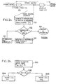
- la figure 2a représente, de manière illustrative, une succession d'étapes permettant une mise en oeuvre avantageuse d'un procédé de création d'un bruit de confort, à l'émission, dans le contexte de l'invention ;
- la figure 2b représente, sous forme d'organigramme, un mode préférentiel de création de trames de description de silence ;
- la figure 2c représente, de manière illustrative, la succession d'étapes permettant une mise en oeuvre avantageuse du procédé de création d'un bruit de confort, à la réception, dans le contexte de l'invention ;
- la figure 2d représente, de manière illustrative, la succession d'étapes permettant la mise en oeuvre du procédé de création d'un bruit de confort, dans le cas où le codeur de parole est de type prédictif mettant en oeuvre un filtre LPC ;
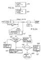
- la figure 2e représente, de manière illustrative, sous forme de blocs fonctionnels, le schéma d'un dispositif de création à l'émission d'un bruit de confort, conformément au procédé de la figure 2a ;
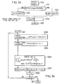
- la figure 3a représente, sous forme de blocs fonctionnels, un schéma du dispositif de création, à l'émission, d'un bruit de confort, conformément au procédé de la figure 2d, en particulier pour un codeur de parole de type prédictif ;
- la figure 3b représente un détail de réalisation d'un générateur de bruit de confort mis en oeuvre dans le dispositif représenté en figure 3a ;
- la figure 3c représente, sous forme d'un organigramme fonctionnel, l'ensemble des étapes successives permettant d'engendrer un signal de commande d'émission ou de non-émission d'une trame descriptive de silence ;
- la figure 3d représente, sous forme d'un organigramme fonctionnel, l'ensemble des étapes successives permettant de créer, coder et transmettre une trame de description de silence ;
- la figure 3e représente, sous forme d'un organigramme fonctionnel, l'ensemble des étapes successives permettant d'engendrer un signal d'excitation, selon l'invention ;
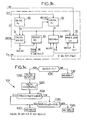
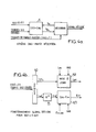
- la figure 4a représente, sous forme de blocs fonctionnels, un schéma du dispositif de création, à la réception, d'un bruit de confort, conformément au procédé de la figure 2c ;
- la figure 4b représente un détail de réalisation du générateur de bruit de confort mis en oeuvre dans le dispositif représenté figure 4a.
- FIG. 2a represents, in an illustrative manner, a succession of steps allowing an advantageous implementation of a method of creating comfort noise, on emission, in the context of the invention;
- FIG. 2b represents, in the form of a flowchart, a preferential mode of creation of silence description frames;
- FIG. 2c represents, in an illustrative manner, the succession of steps allowing an advantageous implementation of the method of creating comfort noise, on reception, in the context of the invention;
- FIG. 2d represents, in an illustrative manner, the succession of steps allowing the implementation of the method for creating comfort noise, in the case where the speech coder is of the predictive type implementing an LPC filter;
- FIG. 2e represents, by way of illustration, in the form of functional blocks, the diagram of a device for creating a comfort noise, in accordance with the method of FIG. 2a;
- FIG. 3a represents, in the form of functional blocks, a diagram of the device for creating, upon transmission, a comfort noise, in accordance with the method of FIG. 2d, in particular for a speech coder of predictive type;
- Figure 3b shows a detail of a comfort noise generator implemented in the device shown in Figure 3a;
- FIG. 3c represents, in the form of a functional flowchart, the set of successive steps making it possible to generate a signal for controlling the transmission or non-transmission of a descriptive frame of silence;
- FIG. 3d represents, in the form of a functional flowchart, the set of successive steps making it possible to create, code and transmit a frame of description of silence;
- FIG. 3e represents, in the form of a functional flowchart, all of the successive steps making it possible to generate an excitation signal, according to the invention;
- FIG. 4a represents, in the form of functional blocks, a diagram of the device for creating, upon reception, a comfort noise, in accordance with the method of FIG. 2c;
- Figure 4b shows a detail of the comfort noise generator used in the device shown in Figure 4a.
En premier lieu, on rappellera, en liaison avec la figure 1 relative à l'art antérieur, qu'un dispositif de création d'un bruit de confort classique dans un système de transmission numérique de parole comporte, à l'émission, outre un codeur de parole, un détecteur d'activité vocale, noté DAV, et un générateur CNG. L'ensemble permet, à l'émission, de transmettre périodiquement des trames descriptives de silence ou trames SID, selon l'une des méthodes décrites précédemment dans la description sur un canal de transmission proprement dit.Firstly, we will recall, in conjunction with the Figure 1 relating to the prior art, that a creation of a classic comfort noise in a digital speech transmission includes, on transmission, in addition to a speech coder, a voice activity detector, noted DAV, and a CNG generator. The set allows, transmission, periodically transmit frames descriptive of silence or SID frames, according to one of methods previously described in the description on a transmission channel proper.
A la réception, un décodeur de parole, décodeur de type prédictif lorsque le codeur de parole utilisé à l'émission est également un codeur de type prédictif, permet d'effectuer le décodage des signaux de parole lorsque ceux-ci sont transmis, respectivement des trames SID, et la création grâce à un générateur CNG à la réception d'un bruit de confort correspondant.On reception, a speech decoder, predictive type when the speech coder used at the emission is also a predictive type coder, allows decoding speech signals when these are transmitted, respectively SID frames, and creation thanks to a CNG generator upon receiving a noise corresponding comfort.
Ainsi qu'on l'a représenté en outre en figure 2a, la transmission numérique de parole est assurée en mode discontinu, cette transmission consistant donc en des périodes actives successives au cours desquelles des trames de signal de parole codé sont transmises, entrecoupées de périodes inactives au cours desquelles aucune trame de signal de parole n'est transmise. La durée respective de ces périodes est quelconque en raison du caractère asynchrone de la transmission.As shown further in Figure 2a, the digital speech transmission is ensured in discontinuous, this transmission therefore consisting of successive active periods during which frames coded speech signal are transmitted, interspersed with inactive periods during which no signal frame speech is not transmitted. The respective duration of these periods is arbitrary due to the asynchronous nature of the transmission.
Ainsi qu'on l'observera en outre sur la figure 2a précitée, le procédé de création d'un bruit de confort, avantageusement dans le contexte de l'invention, est mis en oeuvre à l'émission, de préférence suite à la détection d'une période inactive. La détection d'une période inactive peut par exemple être réalisée à partir du signal délivré par un détecteur d'activité vocale DAV, auquel une temporisation est appliquée, afin de s'assurer du passage effectif en période inactive. Cette temporisation peut également être ajustée afin de tenir compte de la durée de la période de détection, représentée en figure 2a, pour assurer une mise en oeuvre correcte de la création du bruit de confort. Sur la figure 2a précitée, la période de détection est représentée par un intervalle délimité par des pointillés suivant la période active considérée.As will be further observed in Figure 2a mentioned above, the process for creating a comfort noise, advantageously in the context of the invention, is set works on the broadcast, preferably following the detection of a inactive period. Detection of an inactive period can for example be made from the signal delivered by a voice activity detector DAV, at which a time delay is applied, to ensure the effective passage in period inactive. This time delay can also be adjusted to take into account the duration of the detection period, shown in Figure 2a, to ensure implementation correct creation of comfort noise. In Figure 2a above, the detection period is represented by a interval delimited by dotted lines according to the period active considered.
Suite à la détection de chaque période inactive, on
engendre et on transmet, à l'étape 100 de la figure 2a, dès
la fin de la période de détection précitée, une trame SID ou
de description de silence. Cette trame de description de
silence consiste en un ensemble de paramètres codés
descriptifs du bruit de confort. Cette trame de description
de silence constitue en fait la première trame inactive de la
période inactive suivant la période active et la période de
détection précédemment citées.Following the detection of each inactive period, we
generates and transmits, in
Ainsi qu'on l'observera en outre sur la figure 2a,
pour toute trame inactive courante successive de cette
période inactive, on analyse et on mémorise ensuite, en une
étape 101, le spectre de fréquences de cette trame inactive
courante considérée. Le spectre de fréquences de la trame
inactive courante précitée est ensuite comparé, en une étape
102, à un spectre de fréquences de référence dont l'obtention
sera décrite ultérieurement dans la description.As will also be observed in FIG. 2a,
for any successive current inactive frame of this
inactive period, we analyze and then store, in one
Sur critère d'identité des spectres de fréquences de la trame courante et de référence, ainsi que représenté à l'étape 102 précitée,
- soit il est prévu de surseoir à toute transmission, notamment celle d'une nouvelle trame de description de silence, trame SID,
- soit, sur critère d'absence d'identité des spectres de fréquences de la trame courante et de référence, on engendre et on transmet, en une étape 100, cette étape 100 étant réalisée, pour chaque trame SID, selon la même technique utilisée pour la première trame SID, une nouvelle trame de description de silence pendant cette trame inactive courante. Sur la figure 2a, on indique que le sursis de transmission de toute nouvelle trame, sur critère d'identité des spectres de fréquences de la trame de courante et de référence, porte la référence 104.
- either it is planned to postpone any transmission, in particular that of a new silence description frame, SID frame,
- or, on the criterion of absence of identity of the frequency spectra of the current frame and of reference, one generates and transmits, in a
step 100, thisstep 100 being carried out, for each SID frame, according to the same technique used for the first SID frame, a new silence description frame during this current inactive frame. In FIG. 2a, it is indicated that the suspension of transmission of any new frame, on the criterion of identity of the frequency spectra of the current and reference frame, carries thereference 104.
Avantageusement, on réduit ainsi le débit de transmission du bruit de confort à celui des seules trames de description de silence dont le spectre de fréquences est différent de celui de la trame de description de silence précédente.Advantageously, this reduces the flow of transmission of comfort noise to that of only description of silence whose frequency spectrum is different than the silence description frame previous.
Dans un mode de réalisation particulier, le spectre
de fréquences de référence peut être formé à partir du
spectre de fréquences du bruit ambiant obtenu lors de la
création de chaque trame de description de silence. Ainsi, on
prévoit avantageusement une étape 103 de mémorisation du
bruit ambiant permettant d'obtenir le spectre de fréquences
de référence pour chaque trame SID.In a particular embodiment, the spectrum
of reference frequencies can be formed from the
frequency spectrum of the ambient noise obtained during the
creation of each silence description frame. So, we
advantageously provides for a
En ce qui concerne l'initialisation du procédé illustré sur la figure 2a, on indique que pour la première trame inactive d'une période inactive, l'usage du spectre de référence est inutile puisque la décision d'émission d'une trame de description de silence ne repose pas dans ce cas sur la comparaison du spectre de fréquences de la trame courante et de celui de référence. Pendant cette première trame SID, ce spectre de référence Sfr est, soit estimé, soit, avantageusement, directement obtenu à partir du spectre de référence calculé pour concevoir la trame SID, et mémorisé pour le traitement des trames inactives suivantes. Ce spectre de référence est rafraíchi à chaque nouvelle trame de description de silence émise, selon la même méthode que celle utilisée pour l'initialiser à la première trame SID d'une période inactive.Regarding the initialization of the process illustrated in FIG. 2a, it is indicated that for the first inactive frame of an inactive period, the use of the spectrum of reference is useless since the decision to issue a silence description frame in this case is not based on comparison of the frequency spectrum of the current frame and the reference one. During this first SID frame, this reference spectrum Sfr is either estimated or advantageously directly obtained from the spectrum of reference calculated to design the SID frame, and stored for processing subsequent inactive frames. This spectrum of reference is refreshed with each new frame of description of silence issued, using the same method as that used to initialize it to the first SID frame of a inactive period.
L'estimation du spectre de fréquences calculé pour chaque trame SID et qui peut également constituer le spectre de fréquences de référence peut être effectué selon le mode de réalisation préférentiel qui sera maintenant décrit en liaison avec la figure 2b.The estimated frequency spectrum calculated for each SID frame and which can also constitute the spectrum of reference frequencies can be performed according to the mode preferential realization which will now be described in link with Figure 2b.
Dans le mode de réalisation de la figure 2b, on établit chaque trame de description de silence, trame SID, selon un processus particulier permettant en quelque sorte d'adapter chaque trame SID à l'évolution du bruit ambiant, et donc de prendre en compte, pour la création du spectre de la trame SID, certains éléments spécifiques de cette évolution.In the embodiment of FIG. 2b, we establishes each silence description frame, SID frame, according to a particular process allowing in a way adapt each SID frame to changes in ambient noise, and therefore to take into account, for the creation of the spectrum of the SID frame, some specific elements of this evolution.
Ainsi qu'on l'a représenté sur la figure 2b, le
processus d'établissement de chaque trame de description de
silence peut comprendre l'étape consistant à déterminer le
spectre de fréquences moyen des trames inactives successives
pour établir un spectre de fréquences moyen passé, noté SFmp,
cette étape portant la référence 1041 sur la figure 2b.As shown in Figure 2b, the
process of establishing each description frame of
silence can understand the step of determining the
average frequency spectrum of successive inactive frames
to establish a past average frequency spectrum, denoted SFmp,
this step bearing the
Dans ce cas, le spectre de fréquences moyen passé Smp
vérifie la relation (1) :
![]()
![]()
Dans cette relation, on indique que, pour une pluralité de trames successives inactives, notées SF1, SFi, SFn, antérieures à la trame inactive courante dont le spectre de fréquences est noté SFc, le spectre de fréquences moyen passé correspond à la moyenne arithmétique sur les n spectres de fréquences des n trames inactives successives précitées.In this relation, we indicate that, for a plurality of successive inactive frames, denoted SF1, SFi, SFn, prior to the current inactive frame whose spectrum of frequencies is denoted SFc, the average frequency spectrum past corresponds to the arithmetic mean over the n spectra frequencies of the aforementioned successive n inactive frames.
La création proprement dite de la trame SID est alors
réalisée à l'étape 1042 suivante.The actual creation of the SID frame is then
performed in
L'étape 1042 précitée consiste en un test d'identité
du spectre de fréquences moyen passé et du spectre de
fréquences de la trame inactive courante symbolisée par la
relation (2) : SFc ≡ SFmp.The
On indique que le critère d'identité ne correspond pas à une identité stricte des spectres de fréquences comparés, une loi ou critère de correspondance pouvant être établi. Cette étape permet en fait de réaliser une mesure de stationnarité locale du spectre de fréquences.It is indicated that the identity criterion does not correspond not a strict identity of frequency spectra compared, a law or criterion of correspondence which can be established. This step actually makes it possible to measure local stationarity of the frequency spectrum.
Sur critère d'identité des spectres de fréquences
précités, on sélectionne à l'étape 1043 comme trame de
description de silence SID le spectre moyen passé SFmp, et,
sur absence d'identité des spectres de fréquences
précédemment cités, en une étape 1044, le spectre de
fréquences de la trame inactive courante correspondante. On identity criteria of frequency spectra
above, we select in
Ce mode opératoire permet alors, de manière particulièrement avantageuse, d'estimer le spectre de silence de toute trame inactive courante selon qu'une telle trame appartient, soit à une zone spectrale localement stationnaire, soit à une zone spectrale non stationnaire.This operating mode then allows, in a particularly advantageous, to estimate the spectrum of silence of any current inactive frame depending on whether such a frame belongs either to a locally stationary spectral zone, or to a non-stationary spectral zone.
Bien entendu, le nombre n de trames inactives successives sur lesquelles le calcul du spectre moyen passé est arbitraire, celui-ci peut par exemple être pris égal de façon à obtenir un intervalle de temps correspondant de l'ordre de 100 ms. On indique en outre que la trame de description de silence SID ainsi constituée est soumise à quantification préalablement à sa transmission.Of course, the number n of inactive frames successive on which the calculation of the past average spectrum is arbitrary, this can for example be taken equal to so as to get a corresponding time interval of around 100 ms. It is further indicated that the weft of description of SID silence thus constituted is subject to quantification prior to its transmission.
On se réfère maintenant à la figure 2c pour décrire une création d'un bruit de confort dans un système de transmission numérique de parole discontinue, à la réception.We now refer to Figure 2c to describe creation of comfort noise in a digital discontinuous speech transmission, at reception.
Bien entendu, les trames SID ont été émises au préalable comme précédemment décrit.Of course, the SID frames were sent to the as previously described.
En référence à la figure 2c, on décode, pour chaque
trame de description de silence, successive, l'ensemble des
paramètres codés descriptifs du bruit de confort, pour
engendrer des paramètres décodés, en une étape 200, puis à
synthétiser au niveau du décodeur de parole, après traitement
des paramètres décodés, les paramètres permettant au décodeur
de parole de synthétiser le bruit de confort correspondant,
en une étape 201. On indique en particulier que le traitement
des paramètres décodés peut consister en un recodage
spécifique approprié.With reference to FIG. 2c, we decode, for each
silence description frame, successive, the set of
coded parameters describing comfort noise, for
generate decoded parameters, in a
Avantageusement, cette réalisation convient bien lorsque le codeur de parole et le décodeur de parole utilisés à l'émission, respectivement à la réception, sont de type prédictif.Advantageously, this embodiment is well suited when the speech coder and speech decoder used on transmission, respectively on reception, are of the type predictive.
Dans un tel cas, le signal décodé est obtenu en filtrant un signal d'excitation, ce signal provenant de dictionnaires d'innovation plus éventuellement d'une excitation à long terme, par un filtre de synthèse LPC désigné ci-après par filtre LPC.In such a case, the decoded signal is obtained by filtering an excitation signal, this signal coming from innovation dictionaries more than one long-term excitation, by an LPC synthesis filter hereinafter referred to as the LPC filter.
On engendre alors un signal d'excitation dont le spectre a des caractéristiques voisines de celles d'un bruit blanc pour exciter un filtre LPC permettant en fait d'effectuer la synthèse du signal pour produire le bruit de confort.We then generate an excitation signal whose spectrum has characteristics similar to those of noise white to excite an LPC filter actually allowing perform signal synthesis to produce noise comfort.
Dans un tel cas, les paramètres représentant le spectre du bruit ambiant sont alors donnés par les coefficients du filtre LPC, pour l'enveloppe du spectre, et par l'énergie du signal d'excitation pour le niveau du spectre précité.In such a case, the parameters representing the ambient noise spectrum are then given by the coefficients the LPC filter, for the spectrum envelope, and by the energy of the excitation signal for the spectrum level supra.
En se référant à la figure 2d, les mêmes étapes que celles de la figure 2a comportent les mêmes références affectées d'un indice ' en ce qui concerne les opérations relatives à la transmission d'une trame de description de silence.Referring to Figure 2d, the same steps as those of Figure 2a have the same references assigned an index 'with regard to operations relating to the transmission of a description frame of silence.
Conformément au mode de mise en oeuvre représenté en figure 2d, on fonde alors la décision de transmission d'une trame SID ou de non-transmission d'une telle trame sur le caractère de stationnarité du filtre LPC d'une part, et, d'autre part, sur le caractère de stationnarité de l'énergie d'excitation.In accordance with the mode of implementation represented in Figure 2d, we then found the decision to transmit a SID frame or non-transmission of such a frame on the stationarity of the LPC filter on the one hand, and, on the other hand, on the character of stationarity of energy excitation.
Ainsi, suite à la transmission de la première trame SID à l'étape 100', on compare le filtre LPC de la trame courante, noté Fc, par mémorisation en 101' du filtre courant Fc, puis comparaison en 102' du filtre courant Fc au filtre de référence Fr obtenu et mémorisé pendant la précédente trame SID selon l'étape 103'.Thus, following the transmission of the first frame SID in step 100 ', we compare the LPC filter of the frame current, noted Fc, by storing in 101 'the current filter Fc, then comparison at 102 'of the current filter Fc to the filter of reference Fr obtained and memorized during the previous one SID frame according to step 103 '.
Sur absence d'identité des filtres précités à l'étape
102', une nouvelle trame SID est transmise à l'étape 100'.
Les étapes 100', 101', 102' et 103' sont sensiblement
inchangées par rapport aux étapes 100, 101, 102 et 103 de la
figure 2a.Absence of identity of the filters mentioned above in the step
102 ', a new SID frame is transmitted in step 100'.
Steps 100 ', 101', 102 'and 103' are substantially
unchanged from
Si, au contraire, les filtres Fc relatifs aux filtres courants et Fr relatifs aux filtres de référence sont identiques, on estime l'énergie d'excitation de la trame courante Ec, en une étape 104'a, et on compare, en une étape 104'c, l'énergie d'excitation précitée Ec de la trame courante à l'énergie Er de référence estimée pendant la trame SID précédente. Cette estimation est représentée en une étape 104'b sur la figure 2d.If, on the contrary, the filters Fc relating to the filters currents and Fr relative to the reference filters are identical, we estimate the excitation energy of the frame current Ec, in one step 104'a, and we compare, in one step 104'c, the aforementioned excitation energy Ec of the frame current at the reference energy Er estimated during the frame Previous SID. This estimate is represented in one step 104'b in Figure 2d.
Dans le cas où, en réponse au test de l'étape 104'c,
la comparaison de l'énergie d'excitation de la trame courante
à celle de l'énergie de référence est significative, cette
comparaison pouvant consister en une comparaison de la
différence de ces énergies par rapport à une valeur de seuil
E0, on crée et on transmet une nouvelle trame SID par retour à
l'étape 100' précédemment décrite. Si, au contraire, en
réponse au test de l'étape 104'c, la différence entre les
énergies d'excitation précitées n'est pas significative, on
surseoit à toute transmission d'une trame en l'étape 104'd
analogue de l'étape 104d de la figure 2a.In the case where, in response to the test of step 104'c, the comparison of the excitation energy of the current frame to that of the reference energy is significant, this comparison may consist of a comparison of the difference of these energies compared to a threshold value E 0 , a new SID frame is created and transmitted by returning to step 100 'previously described. If, on the contrary, in response to the test of step 104'c, the difference between the aforementioned excitation energies is not significant, we delay any transmission of a frame in
Pour assurer la comparaison des filtres LPC, on peut utiliser des critères de distance mis en oeuvre notamment par les méthodes de quantification vectorielles des filtres LPC. Les distances précitées peuvent consister en la distance d'ITAKURA-SAITO, celle du maximum de vraisemblance, ou des distances euclidiennes calculées sur des paramètres issus des coefficients LPC, paires de raies spectrales, ou log area ratios, par exemple.To ensure the comparison of the LPC filters, it is possible to use distance criteria implemented in particular by the vector quantization methods of the LPC filters. The aforementioned distances can consist of the distance from ITAKURA-SAITO, that of the maximum likelihood, or Euclidean distances calculated on parameters derived from LPC coefficients, pairs of spectral lines, or log area ratios, for example.
En ce qui concerne le caractère de stationnarité en énergie du signal d'excitation, l'absence de linéarité de la sensibilité du système d'écoute humain est exploitée dans les quantificateurs de gain utilisés dans les codeurs. Pour cette raison, le processus de codage précédemment décrit effectue de préférence la comparaison entre l'énergie de l'excitation de la trame courante Ec avec l'énergie de référence Er à partir des indices de quantification de ces énergies. Afin de simplifier la procédure, le quantificateur utilisé est celui servant au calcul de l'énergie codée dans les trames SID. Regarding the character of stationarity in energy of the excitation signal, the lack of linearity of the sensitivity of the human listening system is exploited in gain quantizers used in coders. For this reason, the previously described coding process performs preferably the comparison between the energy of the excitation of the current frame Ec with the reference energy Er to from the quantification indices of these energies. In order to simplify the procedure, the quantifier used is that used to calculate the energy encoded in the SID frames.
Le processus d'estimation du filtre LPC et de l'estimation de l'énergie d'excitation pour les trames de description de silence SID sera décrit ultérieurement dans la description, pour une réalisation avantageuse d'un dispositif générateur de bruit de confort correspondant.The LPC filter estimation process and the estimation of the excitation energy for the frames of description of SID silence will be described later in the description, for an advantageous embodiment of a device corresponding comfort noise generator.
Une description plus détaillée d'un dispositif de création d'un bruit de confort dans un système de transmission numérique de parole discontinue, ce dispositif mettant bien entendu en oeuvre la création d'un tel bruit de confort, ainsi que mentionné précédemment dans la description, sera maintenant donnée en liaison avec la figure 2e.A more detailed description of a creation of comfort noise in a transmission system digital discontinuous speech, this device of course implements the creation of such comfort noise, as previously mentioned in the description, will now given in connection with Figure 2e.
Ainsi qu'on l'a représenté sur la figure 2e en
particulier, le dispositif précité comprend, associé à un
codeur de parole portant la référence 1, un module 2 de
détection de la fin de chaque période active pendant une
période de détection suivant chaque période active. On
comprend par exemple que le module 2 peut être constitué par
un détecteur d'activité vocale de type classique, interconnecté
au codeur de parole 1 et délivrant un signal logique,
noté VADin représentatif de la présence d'une période
d'activité pendant laquelle des trames de parole codée sont
transmises, respectivement d'une période d'absence d'activité
pendant laquelle des trames de description de silence doivent
être transmises, ou au contraire aucune trame n'est
transmise.As shown in Figure 2e in
particular, the aforementioned device comprises, associated with a
speech coder labeled 1,
En outre, ainsi que représenté sur la même figure 2e,
un générateur CNG portant la référence 3 est associé, d'une
part, au codeur de parole 1, et, d'autre part, au module 2
d'activité vocale. Un multiplexeur 4 reçoit, d'une part, les
trames de parole codées délivrées par le codeur de parole 1
et les signaux constitués par les trame de description de
silence ou trames SID codées délivrées par le générateur
CNG 3, respectivement un signal représentatif du type de
transmission à assurer délivré par ce même générateur CNG 3,
et portant la référence VADout. Furthermore, as shown in the same figure 2e,
a CNG generator bearing the
D'une manière générale, on indique que le dispositif
tel que représenté en figure 2e, reprend les principes du
processus décrit ci-avant. Le générateur CNG 3 comprend un
module 3a de création et de transmission conditionnelle,
pendant les périodes d'inactivité, d'une trame de description
de silence, consistant en un ensemble de paramètres codés
descriptifs du bruit de confort, un module 3b d'analyse et de
mémorisation du spectre de fréquences de toute trame inactive
courante, un module 3c de comparaison du spectre de
fréquences de la trame inactive courante à un spectre de
fréquences de référence délivrant un signal de commande
déterminé sur critère d'identité et d'absence d'identité des
spectres de fréquences de la trame courante et de référence,
un module 3d d'estimation du type de transmission pour la
trame courante délivrant pour toute trame un signal VADout à
3 niveaux codant l'information respectivement trame active,
trame non transmise et trame de description de silence.In general, it is indicated that the device
as shown in figure 2e, takes up the principles of
process described above. The
Ce module 3d reçoit, d'une part, le signal produit
par le module 2 de détection d'activité vocale, d'autre part,
le signal de comparaison produit par le module 3c ainsi
qu'indiqué ci-après. Lorsque la trame courante est active, le
module 3d retransmet cette information dans le signal VADout.
Sinon, lorsque la trame courante est la première trame
inactive de la période active, le module 3d attribue au
signal VADout la valeur correspondant à l'information trame
de description de silence, autorisant ainsi la transmission
d'une nouvelle trame de description de silence.This 3d module receives, on the one hand, the signal produced
by the voice
Si la trame courante est une trame inactive mais ne
constitue pas la première trame inactive d'une zone
d'inactivité, le module 3c compare le spectre de fréquences
de la trame courante avec le spectre de fréquences de
référence, et sur critère d'identité et d'absence d'identité
de ces spectres, délivre le signal CMP représentatif
respectivement de l'information trame non transmise et trame
de description de silence. Dans ce cas, le module 3d, à
partir du signal CMP, assure le codage dans le signal VADout
de l'information de transmission permettant de surseoir à
toute transmission lors de l'identité des spectres de
fréquences de la trame courante et de référence et de
réaliser la transmission d'une nouvelle trame de description
de silence lors de l'absence d'identité de ces spectres.If the current frame is an inactive frame but does not
is not the first inactive frame in an area
of inactivity,
Les modules 3a et 3b échangent avec le codeur de
parole un certain nombre de signaux de gestion du codeur de
parole, notés Sg : en entrée, ces modules reçoivent les
données permettant l'évaluation des spectres de fréquences de
la trame courante, module 3b, et d'un certain nombre de
trames antérieures à la trame courante, module 3a, en sortie,
selon les besoins du codeur de parole, le module 3a
communique le cas échéant au codeur de parole les signaux
permettant de remettre à jour ses mémoires, pour éviter une
désynchronisation avec le décodeur de parole situé à la
réception.
En entrée, le module 3a reçoit également le spectre
de fréquences de la trame courante engendré par le module 3b,
signal SFc.At the input, the
Une description plus détaillée d'un dispositif de
création d'un bruit de confort sera maintenant donnée en
liaison avec la figure 3a dans le cas particulier avantageux
dans lequel le codeur de parole 1 est un codeur de parole
prédictif, comportant pour chaque trame de parole un module
d'analyse LPC d'ordre d'analyse M, l'ordre d'analyse étant
défini à partir du nombre de coefficients du filtre LPC,
produisant notamment les (M+1) coefficients de fonction
d'autocorrélation Acf du signal de parole, les M paramètres
représentatifs du filtre LPC de la trame, notés Lpc, étant
codés à l'aide d'une méthode de codage prédictif utilisant
pour chaque trame les paramètres Lpc des trames précédentes.
Le codage prédictif des paramètres Lpc n'est pas nécessaire
pour le fonctionnement du présent dispositif, mais présente
cependant des répercussions sur la conception de ce dernier.
Dans le cas d'un codeur n'utilisant pas de codage prédictif
des paramètres Lpc, le dispositif pourra facilement être
simplifié.A more detailed description of a
comfort noise will now be given in
connection with FIG. 3a in the particular advantageous case
in which the
Le codeur de parole 1 élabore et mémorise par exemple
à l'aide de techniques d'analyse-par-synthèse un signal
d'excitation, noté dans ce qui suit Exc, identique à celui
calculé au décodeur pour exciter le filtre de synthèse LPC.The
La figure 3a reprend l'architecture générale du
dispositif représenté précédemment en figure 2e. Le générateur
CNG 3 reçoit, du codeur de parole 1 de type prédictif,
la fonction d'autocorrélation Acf du signal de parole, les
paramètres Lpc de la trame précédente, et, le cas échéant, un
certain nombre d'échantillons du signal d'excitation Exc(n)
partiellement constitutifs du signal d'excitation Exc, issus
des trames précédentes. On indique que l'introductio des
échantillons précités est conditionnelle à l'utilisation,
pour la synthèse du bruit de confort, de l'excitation à long
terme du codeur prédictif.Figure 3a shows the general architecture of the
device previously shown in Figure 2e. The
Une description plus détaillée du générateur CNG 3
sera maintenant donnée en liaison avec la figure 3b. Ce mode
de réalisation correspond au cas où le codeur de parole est
un codeur de type prédictif.A more detailed description of the
Ainsi qu'on l'observera sur la figure 3b, le
générateur CNG 3 comporte un module 30 de calcul des
paramètres relatifs à la trame courante Pc, recevant le
signal de fonction d'autocorrélation du signal de parole Acf
et produisant en sortie les signaux correspondant aux
paramètres de la trame courante Pc. Ces paramètres comprennent
le filtre courant Fc et l'énergie d'excitation courante
Ec.As will be seen in FIG. 3b, the
Le générateur CNG 3 comprend également, ainsi que
représenté sur la figure 3b, un module 31 de décision
d'émission d'une trame de parole codée, ou d'une trame de
description de silence, trame SID, ou de suspension d'émission,
recevant le signal d'activité vocale VADin et les
paramètres relatifs à la trame courante Pc et les paramètres
de référence Pr délivrés par un module 32, lequel sera décrit
ultérieurement. Ce module 31 délivre un signal de type de
transmission à trois niveaux, signal noté VADout, un premier
niveau VADout = 0 correspondant à l'absence totale d'émission
pendant une trame courante inactive, c'est-à-dire pour le
signal VADin = 0, signal délivré par le module 2 de détection
d'activité vocale, un deuxième niveau VADout = 1
correspondant à l'émission d'une trame de parole codée
pendant une trame active, c'est-à-dire pour VADin = 1, et un
troisième niveau VADout = 2 correspondant à l'émission d'une
trame SID pendant une trame inactive, c'est-à-dire pour
VADin = 0.The
Le générateur CNG 3 comprend également un module 32
calculant conditionnellement au signal entrant VADout les
signaux correspondant aux paramètres de référence Pr calculés
à chaque trame SID. Ces paramètres comprennent le filtre de
référence Fr et l'énergie d'excitation de référence Er. Ce
module reçoit en entrée les signaux d'autocorrélation Acf et
les paramètres de la trame courante Pc.The
Le générateur CNG 3 comprend ensuite un module 33
générateur de trame de description de silence SID sous forme
codée, recevant le signal de type de transmission VADout, et
les signaux correspondant aux paramètres de référence Pr, et
délivrant conditionnellement un signal de trame de description
de silence codée.The
Le générateur CNG 3 comprend ensuite un module 34
générateur d'un signal d'excitation Exc, recevant le signal
de type de transmission VADout, les signaux correspondant aux
paramètres de référence Pr et, comme on le verra plus loin,
un certain nombre d'échantillons passés Excpas du signal
d'excitation fournis par le codeur de parole. Ce module
délivre, conditionnellement au signal VADout, un signal
d'excitation pour la trame courante Exc.The
Le générateur CNG 3 comprend enfin un module 35
générateur d'un signal descriptif des paramètres de filtrage
Lpc réactualisés, recevant le signal de type de transmission
VADout, et les signaux correspondant aux paramètres de
référence Pr, le signal descriptif des paramètres Lpc des
trames précédentes délivré par le codeur de parole 1, et
réactualisant, conditionnellement à VADout, ce signal pour la
trame courante, Lpcr.The
Le fonctionnement du module générateur CNG 3 est le
suivant :The operation of the
En entrée, le module générateur CNG 3 reçoit l'information VADin trame inactive 0, trame active 1, délivrée par le module 2 détecteur d'activité vocale. Il reçoit également du module codeur de parole 1 et pour chaque trame :
- le signal de fonction d'autocorrélation du signal de parole de la trame courante Acf,
- le signal descriptif des paramètres Lpc relatifs au moins à la trame précédente, ce signal étant référencé Lpc et correspondant aux paramètres Lpc d'au moins la trame précédente du codeur 1, paramètres utilisés par le quantificateur prédictif, du codeur de parole,
- le cas échéant le signal d'excitation passé.
- the autocorrelation function signal of the speech signal of the current frame Acf,
- the descriptive signal of the parameters Lpc relating to at least the previous frame, this signal being referenced Lpc and corresponding to the parameters Lpc of at least the previous frame of the
coder 1, parameters used by the predictive quantizer, of the speech coder, - if applicable, the excitation signal passed.
Le module générateur CNG 3 produit en sortie, pour
chaque trame, le signal de type de transmission à trois
niveaux VADout précédemment mentionné.The
Pour les trames de description de silence SID, le
générateur CNG 3 produit en outre les paramètres d'insertion
de silence codés, constitutifs des trames SID.For SID silence description frames, the
Pour les trames inactives, c'est-à-dire telles que le
signal d'activité délivré par le module d'activité vocale 2,
VADin, est égal à 0, le module générateur CNG 3 délivre de
plus, le cas échéant, un signal d'excitation de la trame
courante Exc, et le signal Lpcr des paramètres Lpc
réactualisés.For inactive frames, i.e. such as the
activity signal delivered by the
Le fonctionnement global du générateur CNG 3 peut être résumé de la façon ci-après :
- si le signal VADin est égal à 1, la trame est
active et le générateur
CNG 3 se contente de répercuter cette information dans VADout = 1 ; - sinon,
le module 30 évalue tout d'abord les paramètres relatifs à la trame courante Pc.
- if the signal VADin is equal to 1, the frame is active and the
generator CNG 3 is content to pass on this information in VADout = 1; - otherwise, the
module 30 first evaluates the parameters relating to the current frame Pc.
Ensuite, le module 31 décide si la trame courante doit être non transmise ou constituer une trame SID à transmettre :
- si la trame courante est la première trame inactive après une période d'activité, alors, c'est une trame SID,
- sinon, le module 31 utilise les paramètres de
référence Pr engendrés
par le module 32 de calcul des paramètres de référence à la précédente trame SID et établit si la trame courante est une trame SID.
- if the current frame is the first inactive frame after an activity period, then it is an SID frame,
- otherwise, the module 31 uses the reference parameters Pr generated by the
module 32 for calculating the reference parameters to the previous SID frame and establishes whether the current frame is an SID frame.
Si la trame courante est une trame SID, alors, VADout = 2, sinon VADout = 0.If the current frame is an SID frame, then, VADout = 2, otherwise VADout = 0.
Si la trame courante est une trame SID, le module 33
code les paramètres de la trame SID.If the current frame is an SID frame, the
Dans les deux cas précédents, c'est-à-dire pour
VADout = 0 ou 2, le module 34 engendre, puis met à jour le
signal d'excitation relatif à la trame courante Exc, et le
module 35 met à jour le signal représentatif des paramètres
Lpc.In the two previous cases, that is to say for
VADout = 0 or 2,
Une description plus détaillée du mode opératoire du module 31 de décision d'émission d'une trame de parole codée, ou d'une trame de description de silence, trame SID, ou de suspension d'émission, sera maintenant donnée en liaison avec la figure 3c.A more detailed description of the operating mode of the module 31 for deciding to transmit a coded speech frame, or a silence description frame, SID frame, or emission suspension, will now be given in conjunction with Figure 3c.
Un test 1020 sur le signal VADin relatif à la trame précédente, indicée t-1, pour déterminer si la trame courante est la première trame inactive, soit VADin(t-1) = 1 pour VADin(t) = 0, provoque en 1021 la création d'un signal VADout = 2, c'est-à-dire la décision de transmission d'une trame SID. A 1020 test on the VADin signal relating to the frame previous, subscripted t-1, to determine if the current frame is the first inactive frame, i.e. VADin (t-1) = 1 for VADin (t) = 0, causes in 1021 the creation of a VADout signal = 2, i.e. the decision to transmit a frame SID.
Au contraire, sur réponse négative au test 1020, soit
lorsque VADin(t-1) = 0, la trame précédente étant inactive,
le filtre LPC relatif à la trame courante est calculé à
l'étape 1022 à partir de la relation (3) :
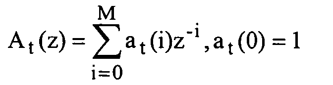
Dans cette relation, on indique que les coefficients at(i) désignent les coefficients du filtre LPC calculés à partir des coefficients d'autocorrélation du signal d'autocorrélation Acf précédemment mentionnés, i désignant l'indice de chaque coefficient.In this relation, it is indicated that the coefficients a t (i) denote the coefficients of the LPC filter calculated from the autocorrelation coefficients of the autocorrelation signal Acf previously mentioned, i denoting the index of each coefficient.
La valeur de ce filtre est comparée à un filtre de
référence de fonction de transfert Aref(z) mémorisé pendant la
trame SID précédente, ainsi que décrit précédemment. Cette
comparaison peut être effectuée à l'aide de la distance
d'Itakura-Saito précitée. Cette distance est comparée à une
valeur de seuil, ce qui permet d'éviter la nécessité de
calcul d'un logarithme et de supprimer toute opération de
division, la comparaison à la valeur de seuil étant réalisée
selon la relation (4) ci-après :
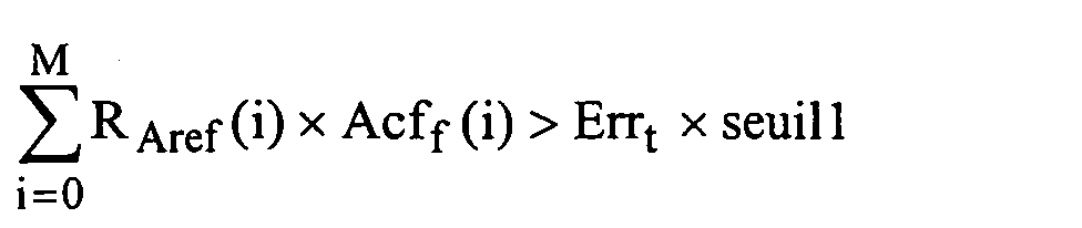
Dans la relation précitée, Errt désigne l'énergie
résiduelle LPC pour la trame courante, somme des carrés du
signal résiduel LPC, cette énergie résiduelle pouvant être
obtenue dans la procédure de calcul du filtre par la méthode
de Levinson/Durbin, RAref désigne une fonction dérivée de
l'autocorrélation des coefficients du filtre de référence
Aref(z) vérifiant la relation (5) :
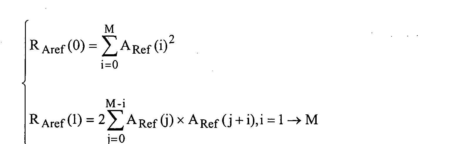
Lorsque l'inégalité de la relation (4) est vérifiée, le filtre LPC n'est pas considéré comme semblable au filtre de référence, la trame courante est alors définie comme une nouvelle trame SID, VADout = 2.When the inequality of relation (4) is verified, the LPC filter is not considered to be similar to the filter reference, the current frame is then defined as a new SID frame, VADout = 2.
Sinon : dans la même étape 1022, une opération
d'estimation de l'énergie de l'excitation de la trame
courante Et est effectuée à partir de l'énergie résiduelle
LPC Errt. Pour procéder à l'estimation de l'énergie d'excitation
courante Et, l'énergie résiduelle LPC Errt est multipliée
par un facteur noté CE estimé par apprentissage. On calcule
ensuite la moyenne de ces énergies sur m trames, m étant par
exemple un entier correspondant à un intervalle de temps de
100 à 200 ms, et l'on procède à une opération de quantification,
notée Q(.), selon la relation (6) :
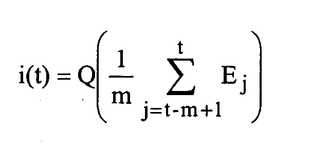
On indique que le nombre m de trames précité est initialisé à 1 au début de chaque zone inactive, puis il peut être incrémenté à chaque trame jusqu'à une valeur maximum déterminée.It is indicated that the aforementioned number m of frames is initialized to 1 at the start of each inactive zone, then it can be incremented at each frame up to a maximum value determined.
L'opération 1023 précitée est alors suivie d'une
opération 1024 consistant à comparer le filtre LPC de la
trame courante et le filtre de référence Aref(z) ainsi que
mentionné précédemment. Sur réponse positive au test 1024
précité, le signal VADout est positionné à 2 à l'étape 1027
autorisant ainsi la transmission d'une trame SID. Sur réponse
négative au test 1024, un test 1025 est alors effectué, ce
test 1025 consistant en un test sur les valeurs quantifiées
de la moyenne des énergies obtenues à la relation (6)
précédente, l'indice de quantification pour la trame courante
i(t) étant comparé à celui de la trame de référence obtenue
pendant la trame SID précédente, notée iref selon la relation
(7) :
Sur réponse positive au test 1025, l'inégalité étant
vérifiée, le niveau d'énergie de l'excitation a changé et la
trame courante est alors définie comme trame SID.On a positive response to
Sur réponse négative au test 1025, la trame courante
est définie comme une trame de silence non transmise 1026, le
signal VADout étant égal à 0.On negative response to
Une description plus détaillée du mode opératoire du module 31 générateur de trame de description de silence, trame SID codée, sera maintenant donnée en liaison avec la figure 3d.A more detailed description of the operating mode of the module 31 silence description frame generator, coded SID frame, will now be given in conjunction with the 3d figure.
D'une manière générale, on indique que lors du codage d'une trame SID, un nouveau filtre de référence Aref(z) est calculé.In general, it is indicated that during the coding of a SID frame, a new reference filter A ref (z) is calculated.
En premier lieu, et pour la réalisation de cette
opération, un filtre LPC moyen passé, dont la fonction de
transfert est notée Apast(z), est évalué à l'étape 1100 selon
la relation (8) :
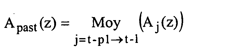
Ce filtre est calculé à partir de la somme des autocorrélations du signal, notées Acf précédemment, des p1 trames précédant la trame courante. Un calcul d'autocorrélation RApast des coefficients de ce filtre est alors réalisé conformément à la méthode donnée par la relation (5) précitée.This filter is calculated from the sum of the signal autocorrelations, denoted Acf previously, of the p 1 frames preceding the current frame. An autocorrelation calculation R Apast of the coefficients of this filter is then carried out in accordance with the method given by the above-mentioned relation (5).
Un test de mesure de stationnarité locale est
effectué en 1101 de manière semblable au test 1024 décrit en
relation avec la figure 3c, conformément à la relation (2)
précédemment mentionnée. La valeur de seuil pour le test 1101
est une valeur particulière égale à seuill. Sur réponse
positive au test 1101 précité, l'étape 1103 permet de
sélectionner le filtre courant comme filtre de référence
selon la relation Aref(z) = At(z) et la nouvelle fonction
d'autocorrélation du filtre de référence RAref est alors
calculée.A local stationarity measurement test is carried out in 1101 in a similar manner to the
Sur réponse négative au test 1101, le filtre moyen
passé est sélectionné comme filtre de référence selon la
relation Aref(z) = Apast(z) et la fonction d'autocorrélation des
coefficients du filtre de référence est réactualisée suivant
la relation (9) :
Une étape de quantification 1104 est alors effectuée
sur les paramètres représentant le filtre de référence sélectionné
précédemment 1104, l'opération de quantification étant
réalisée selon la procédure utilisée par le codeur, le code
ainsi obtenu étant inséré dans la trame SID codée.A
En une étape 1105, l'énergie d'excitation déjà
calculée et quantifiée en 1023 i(t) est insérée dans la trame
SID correspondante et mémorisée comme énergie de référence
iref.In a
En ce qui concerne la synthèse du signal d'excitation,
on indique que iref désignant l'indice de quantification
de l'énergie de référence, gref désigne le gain restitué égal
à la racine carrée de l'énergie moyenne par échantillon,
obtenu par la relation :
Le gain gt de la trame courante est alors donné par :
- gt = gref au début d'une période inactive,
- gt = α x gt-1 + (1-α) x gref en période inactive.
- g t = g ref at the start of an inactive period,
- g t = α xg t-1 + (1-α) xg ref in inactive period.
Dans cette relation, α est un coefficient réel compris entre 0 et 1.In this relation, α is a real coefficient between 0 and 1.
En ce qui concerne le calcul des signaux d'excitation, pour engendrer un signal d'excitation dont le spectre a des caractéristiques voisines de celles d'un bruit blanc et dont l'énergie moyenne est celle transmise au décodeur, une méthode simple de synthèse de ce signal d'excitation peut consister à tirer aléatoirement un signal de densité de probabilité uniforme et d'amplitude donnée, calculée à partir de l'énergie transmise par exemple.Regarding the calculation of the excitation signals, to generate an excitation signal whose spectrum has characteristics close to those of white noise and whose average energy is that transmitted to the decoder, a simple method of synthesizing this excitation signal can consist of randomly drawing a density signal from uniform probability and given amplitude, calculated from of the energy transmitted for example.
Une autre méthode peut consister à synthétiser par tirage aléatoire une excitation de même type que celle utilisée par le codeur de parole, l'avantage de cette deuxième méthode résidant dans la possibilité de réaliser un module externe au décodeur dans la partie réception. D'autre part, d'un point de vue perceptuel, le risque de rupture avec les trames décodées précédentes est plus faible car l'excitation ne change pas brutalement de type.Another method may be to synthesize by random draw an excitation of the same type as that used by the speech coder, the advantage of this second method residing in the possibility of carrying out a module external to the decoder in the reception part. Else on the other hand, from a perceptual point of view, the risk of breaking with the previous decoded frames is weaker because the excitement doesn't suddenly change type.
Le procédé au sens de l'invention permet alors d'utiliser l'excitation LTP et de contrôler le gain de l'excitation globale obtenue par addition de l'excitation LTP et d'une innovation. Le procédé de l'invention est décrit ci-après, en liaison avec la figure 3e.The process within the meaning of the invention then allows to use the LTP excitation and control the gain of the overall excitation obtained by adding the LTP excitation and innovation. The process of the invention is described below, in conjunction with Figure 3e.
Notons tout d'abord que le codeur de parole
communique au module CNG 3 un certain nombre d'échantillons
du signal d'excitation Excpas issus des trames passées,
signal représenté en pointillé dans la figure 3b.First of all, note that the speech coder
communicates to the
Dans ce mode de réalisation, la trame de N échantillons est divisée en N/L blocs de L échantillons sur lesquels sont calculés et codés les paramètres de l'excitation. Selon les besoins du codeur de parole, ces blocs peuvent être subdivisés, la période de calcul des codes de l'excitation à long terme ne correspondant pas nécessairement à celle de l'innovation.In this embodiment, the frame of N samples is divided into N / L blocks of L samples on which the excitation parameters are calculated and coded. according to the needs of the speech coder, these blocks can be subdivided, the calculation period of the excitation codes at long term does not necessarily correspond to that of innovation.
Sur la figure 3e, l'étape 1201 permet d'initialiser à
0 la variable de comptage j relative à la complétude d'un
bloc de N/L échantillons.In FIG. 3e,
Le signal d'excitation Exc constitué par des échantillons Exc(n) avec n = 0 à N-1 est défini pour la trame courante comme la combinaison linéaire d'une excitation de prédiction à long terme, notée eLTP(n), et une excitation innovatrice, notée β u(n), u(n) désignant la forme d'onde innovatrice et β son gain après déquantification, gain que l'on cherche à ajuster, pour chaque bloc, de manière à contrôler l'énergie de l'excitation ainsi engendrée.The excitation signal Exc constituted by samples Exc (n) with n = 0 to N-1 is defined for the current frame as the linear combination of a long-term prediction excitation, denoted e LTP (n), and an innovative excitation, noted β u (n), u (n) designating the innovative waveform and β its gain after dequantification, gain which one seeks to adjust, for each block, so as to control the energy of the excitement thus generated.
Pour chaque bloc d'indice j, les codes des paramètres
de l'excitation à long terme sont tirés aléatoirement, en une
étape 1202. Une contrainte est préférable sur le code du gain
de l'excitation à long terme pour limiter l'énergie de celle-ci.
On obtient ainsi les L échantillons du signal eLTP(n),
avec n = jL+k, k variant de 0 à L-1, sur le bloc, en
utilisant les échantillons du signal passé Excpas fourni par
le codeur de parole.For each block of index j, the codes of the parameters of the long-term excitation are drawn randomly, in a
Le signal d'excitation d'innovation est ensuite
obtenu, en une étape 1203, par tirage aléatoire du code de la
forme d'onde d'innovation. On obtient alors les L
échantillons de la forme d'onde u(n), avec n = jL+k, k
variant de 0 à L-1, sur le bloc.The innovation excitement signal is then
obtained, in a
L'étape 1204 permet de rechercher l'indice de
quantification ind du gain de l'excitation d'innovation, et
donc, par l'opération de déquantification, le gain β associé.
On sélectionnera l'indice permettant d'obtenir sur le bloc
l'énergie moyenne par échantillon la plus proche possible de
la valeur souhaitée gt 2 selon la relation (10) :
=
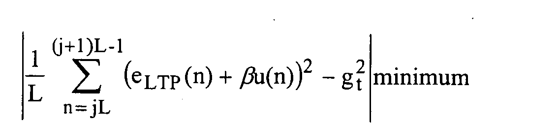
Dans le cas où les gains de l'excitation à long terme
et de l'excitation d'innovation sont quantifiés conjointement
par un quantificateur vectoriel, on peut prévoir qu'à l'étape
1202, l'excitation eLTP(n) est obtenue par tirage aléatoire
des codes représentant le délai LTP, pour un gain égal à 1.
La relation (10) est ensuite modifiée en (11) :
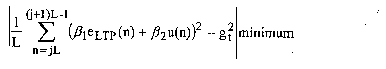
L'étape 1204 est suivie d'une étape 1205 où le signal
d'excitation Exc est mis à jour par le calcul de Exc pour les
échantillons du bloc courant.
Une incrémentation de la variable de comptage j, en une étape
1206 suivie d'un test de la valeur de cette variable, en
1207, permettent de compléter l'obtention du signal
d'excitation pour l'ensemble des échantillons constitutifs
d'une trame.
An increment of the counting variable j, in a
Une description plus détaillée du dispositif générateur d'un bruit de confort dans un système de transmission numérique de parole discontinue, au niveau de la réception, sera maintenant donnée en liaison avec les figures 4a et 4b.A more detailed description of the device comfort noise generator in a transmission system digital discontinuous speech, at the reception, will now be given in conjunction with the figures 4a and 4b.
Ainsi qu'on l'a représenté sur la figure 4a, on indique que le dispositif à la réception comprend un module 5 de décodage du bruit de confort ou, plus particulièrement, dans chaque trame de description de silence successive, de l'ensemble des paramètres codés descriptifs de ce bruit de confort.As shown in Figure 4a, we indicates that the device on reception includes a module 5 comfort noise decoding or, more particularly, in each successive silence description frame, the set of coded parameters describing this noise of comfort.
Le module 5 est associé au décodeur de parole proprement dit et il reçoit l'information relative au type de trame courante traitée par ce module 5, information notée VAD, cette information reproduisant l'information du signal à 3 niveaux VADout engendré à l'émission, ainsi bien entendu que les trames de description de silence ou trames SID codées. Il reçoit en outre du décodeur de parole un signal de gestion Sg assurant la synchronisation avec le décodeur.Module 5 is associated with the speech decoder properly says and receives frame type information current processed by this module 5, information noted VAD, this information reproducing the signal information at 3 VADout levels generated on transmission, as well as of course silence description frames or coded SID frames. he additionally receives from the speech decoder a management signal Sg ensuring synchronization with the decoder.
Le module 5 permet d'engendrer des paramètres descriptifs du bruit de confort PBc relatifs à la trame courante.Module 5 allows to generate parameters descriptions of the comfort noise PBc relating to the frame common.
Le décodeur de signal de parole reçoit, d'une part, les trames de parole codées, et, d'autre part, le signal descriptif des paramètres du bruit de confort PBc relatif à la trame courante. Il délivre par synthèse un signal de parole synthétisé, désigné par le terme signal décodé, sur la figure précitée.The speech signal decoder receives, on the one hand, the coded speech frames, and, on the other hand, the signal description of the PBc comfort noise parameters relating to the current frame. It synthesizes a signal of synthesized speech, designated by the term decoded signal, on the above figure.
Le module 5 représenté en figure 4a sera maintenant
décrit de manière plus détaillée en figure 4b dans le cas où
le décodeur de signal de parole est formé par un décodeur
prédictif. Le module de décodage 5 comporte, au moins, un
démultiplexeur 50 recevant le signal de trame de description
de silence codé transmis et délivrant un signal codé
descriptif des paramètres de filtrage LPC, ce signal relatif
à la trame courante étant noté Lpcc sur la figure 4b, ainsi
que un signal d'indice de gain quantifié iref, descriptif du
niveau du signal d'excitation synthétisé. Ces paramètres sont
utilisés jusqu'à la trame SID suivante.The module 5 shown in Figure 4a will now be described in more detail in Figure 4b in the case where the speech signal decoder is formed by a predictive decoder. The decoding module 5 comprises, at least, a
En outre, un module 51 déquantificateur est prévu, lequel reçoit le signal d'indice de gain quantifié précité et délivre un signal de gain déquantifié, noté gref.In addition, a dequantizer module 51 is provided, which receives the aforementioned quantized gain index signal and delivers a dequantized gain signal, denoted g ref .
Un module de calcul 52 est prévu, lequel reçoit le
signal codé descriptif des paramètres de filtrage LPC relatif
à la trame courante, noté Lpcc, le signal descriptif des
paramètres de filtrage LPC relatif au moins à la trame
précédente, noté Lpc, et l'information de type de transmission
de trame, noté VAD. Le module de calcul 52 délivre alors
le signal LPC mis à jour avec les paramètres LPC de la trame
courante.A
Enfin, un module 53 générateur d'excitation est
prévu, lequel reçoit le signal de gain déquantifié gref, le
cas échéant le signal d'excitation passé et l'information de
type de trame VAD, et délivre le signal d'excitation relatif
à la trame courante Exc.Finally, an
Le module 5 décodeur ne fonctionne que lorsque les trames ne sont pas actives.The decoder module 5 only works when the frames are not active.
En entrée, il reçoit l'information donnée par le signal VAD 0 : trame non transmise, 2 : trame SID et, dans le cas d'une trame SID, les paramètres codés de la trame. Le décodeur de parole fournit d'autre part les données ci-après :
- les paramètres LPC relatifs au moins à la trame précédente utilisés par le quantificateur prédictif, le signal relatif à ces paramètres LPC de la trame précédente étant noté Lpc ;
- le signal d'excitation passée Excpas, mémoire du prédicteur à long terme.
- the LPC parameters relating to at least the previous frame used by the predictive quantizer, the signal relating to these LPC parameters of the previous frame being denoted Lpc;
- the excitation signal passed Excpas, long-term predictor memory.
En sortie, le module 5 de décodage produit pour chaque trame inactive les N nouveaux échantillons du signal d'excitation Exc et des nouveaux paramètres LPC après déquantification, notés Lpc.At output, the decoding module 5 produces for each frame inactivates the N new signal samples Exc excitation and new LPC parameters after dequantification, noted Lpc.
Le décodeur de parole utilise ces données pour réaliser la synthèse des trames inactives.The speech decoder uses this data to synthesize inactive frames.
Lorsque le signal VAD = 2, les paramètres de la trame SID, Lpcc et iref pour l'énergie quantifiée sont décodés et mémorisés. On notera Lpcref et gref les paramètres mémorisés dans cette étape-là. When the signal VAD = 2, the parameters of the frame SID, Lpc c and i ref for the quantized energy are decoded and memorized. We will note Lpc ref and g ref the parameters memorized in this step.
Lorsque VAD = 0, le module de calcul 52 calcule un
nouvel ensemble de paramètres LPC en quantifiant et déquantifiant
Lpcref en utilisant les paramètres passés Lpc fournis
par le décodeur, le gain déquantifié gref ne changeant pas et
le gain relatif à la trame courante gt étant mis à jour selon
la relation précédemment mentionnée dans la description.When VAD = 0, the
Dans les deux cas, le module 53 calcule la nouvelle
excitation Exc relative à la trame courante et la transmet au
décodeur de parole, lequel effectue la synthèse du signal
décodé des trames inactives.In both cases,
On notera que le module 5 décodeur de bruit de confort peut être rendu totalement autonome et implanté de manière externe au décodeur. Dans ce cas, les processus utilisés sont les mêmes moyennant un transfert de certaines fonctions élémentaires du décodeur dans ce module.Note that the noise decoder module 5 of comfort can be made completely autonomous and implanted external to the decoder. In this case, the processes used are the same by transfer of certain basic functions of the decoder in this module.
Enfin, dans un mode de réalisation particulier, les
valeurs préférentielles des paramètres précédemment mentionnées
dans la description étaient les suivantes, pour une
trame N=240 échantillons échantillonnés à une fréquence de
8 kHz :
Le facteur de correction CE et les valeurs précédentes étaient adaptées pour le codeur prédictif G 723 normalisé par l'U.I.T., codeur de type prédictif pour la visiophonie RTC.The correction factor C E and the previous values were adapted for the ITU standard G 723 predictive coder, a predictive coder for PSTN video telephony.
On a ainsi décrit un procédé et un dispositif de création d'un bruit de confort dans un système de transmission numérique de parole discontinue particulièrement performant. Ce procédé et ce dispositif sont particulièrement avantageux dans la mesure où, s'appuyant sur une analyse du signal au cours des périodes inactives, un processus de rafraíchissement des paramètres utilisés pour reproduire le bruit lorsque les caractéristiques de celui-ci ont changé est réalisé. L'envoi de trames SID n'est pas limité à la première trame inactive, ni non plus reproduit périodiquement, mais commandé par le dispositif lui-même, ce qui permet d'assurer une bonne qualité de bruit de confort tout en minimisant le volume de données à transmettre. Ainsi, pour estimer des paramètres permettant de former les trames SID, il est avantageusement mis en oeuvre une méthode efficace prenant en compte la stationnarité ou la non-stationnarité du bruit ambiant, restituant l'évolution de ce dernier.We have thus described a method and a device for creation of comfort noise in a transmission system digital discontinuous speech particularly performance. This method and this device are particularly advantageous insofar as, based on an analysis of the signal during inactive periods a process of refresh of the parameters used to reproduce the noise when the characteristics of it have changed is realized. Sending of SID frames is not limited to the first inactive frame, neither reproduced periodically, but controlled by the device itself, which ensures good comfort noise quality while minimizing volume of data to be transmitted. So, to estimate parameters for forming SID frames it is advantageously implemented an effective method taking into counts the stationarity or non-stationarity of noise ambient, restoring the evolution of the latter.
Pour un dispositif associé à un codeur de parole de type prédictif, dans le but d'estimer la stationnarité en énergie, on effectue une comparaison des énergies du signal d'excitation quantifié, ce qui permet de tirer parti des propriétés perceptuelles du quantificateur de manière simple.For a device associated with a speech coder predictive type, in order to estimate stationarity in energy, we compare the signal energies of quantified excitation, which makes it possible to take advantage of perceptual properties of the quantifier in a simple way.
Pour la synthèse de l'onde excitatrice, on propose un moyen d'utiliser un dictionnaire adaptatif LTP en plus du dictionnaire d'innovation, l'ajustement du gain à l'énergie transmise étant effectué grâce à la mise en oeuvre du procédé au sens de l'invention. Les formes d'ondes excitatrices ainsi créées possèdent en général une plus grande richesse spectrale que celle n'utilisant que les dictionnaires d'innovation.For the synthesis of the excitation wave, we propose a way to use an adaptive LTP dictionary in addition to the dictionary of innovation, adjusting gain to energy transmitted being carried out thanks to the implementation of the method within the meaning of the invention. The exciting waveforms as well created in general have a greater spectral richness than the one using only innovation dictionaries.
Enfin, l'invention, dans le contexte décrit ci-avant, permet la mise en oeuvre et la création d'un bruit de bonne qualité, lequel est synthétisé même lorsque le taux moyen de transmission est faible, et ce, au prix d'une complexité de calcul modérée.Finally, the invention, in the context described above, allows the implementation and creation of good noise quality, which is synthesized even when the average rate of transmission is weak, at the cost of a complexity of moderate calculation.
Claims (3)


Applications Claiming Priority (3)
| Application Number | Priority Date | Filing Date | Title |
|---|---|---|---|
| FR9512039 | 1995-10-13 | ||
| FR9512039A FR2739995B1 (en) | 1995-10-13 | 1995-10-13 | METHOD AND DEVICE FOR CREATING COMFORT NOISE IN A DIGITAL SPEECH TRANSMISSION SYSTEM |
| EP96402150A EP0768770B1 (en) | 1995-10-13 | 1996-10-10 | Method and arrangement for the creation of comfort noise in a digital transmission system |
Related Parent Applications (1)
| Application Number | Title | Priority Date | Filing Date |
|---|---|---|---|
| EP96402150A Division EP0768770B1 (en) | 1995-10-13 | 1996-10-10 | Method and arrangement for the creation of comfort noise in a digital transmission system |
Publications (3)
| Publication Number | Publication Date |
|---|---|
| EP1320087A2 true EP1320087A2 (en) | 2003-06-18 |
| EP1320087A3 EP1320087A3 (en) | 2006-05-17 |
| EP1320087B1 EP1320087B1 (en) | 2008-06-11 |
Family
ID=9483505
Family Applications (3)
| Application Number | Title | Priority Date | Filing Date |
|---|---|---|---|
| EP03018358A Expired - Lifetime EP1372289B1 (en) | 1995-10-13 | 1996-10-10 | Generation of a frame descriptor of silence for generation of comfort noise |
| EP03005562A Expired - Lifetime EP1320087B1 (en) | 1995-10-13 | 1996-10-10 | Synthesis of an excitation signal for use in a comfort noise generator |
| EP96402150A Expired - Lifetime EP0768770B1 (en) | 1995-10-13 | 1996-10-10 | Method and arrangement for the creation of comfort noise in a digital transmission system |
Family Applications Before (1)
| Application Number | Title | Priority Date | Filing Date |
|---|---|---|---|
| EP03018358A Expired - Lifetime EP1372289B1 (en) | 1995-10-13 | 1996-10-10 | Generation of a frame descriptor of silence for generation of comfort noise |
Family Applications After (1)
| Application Number | Title | Priority Date | Filing Date |
|---|---|---|---|
| EP96402150A Expired - Lifetime EP0768770B1 (en) | 1995-10-13 | 1996-10-10 | Method and arrangement for the creation of comfort noise in a digital transmission system |
Country Status (8)
| Country | Link |
|---|---|
| US (1) | US5812965A (en) |
| EP (3) | EP1372289B1 (en) |
| JP (2) | JP3781495B2 (en) |
| KR (1) | KR100357254B1 (en) |
| CN (1) | CN1104710C (en) |
| DE (3) | DE69631318T2 (en) |
| FR (1) | FR2739995B1 (en) |
| HK (2) | HK1057939A1 (en) |
Families Citing this family (59)
| Publication number | Priority date | Publication date | Assignee | Title |
|---|---|---|---|---|
| US5978756A (en) * | 1996-03-28 | 1999-11-02 | Intel Corporation | Encoding audio signals using precomputed silence |
| SE507370C2 (en) * | 1996-09-13 | 1998-05-18 | Ericsson Telefon Ab L M | Method and apparatus for generating comfort noise in linear predictive speech decoders |
| US6269331B1 (en) * | 1996-11-14 | 2001-07-31 | Nokia Mobile Phones Limited | Transmission of comfort noise parameters during discontinuous transmission |
| US5960389A (en) | 1996-11-15 | 1999-09-28 | Nokia Mobile Phones Limited | Methods for generating comfort noise during discontinuous transmission |
| JP3575967B2 (en) * | 1996-12-02 | 2004-10-13 | 沖電気工業株式会社 | Voice communication system and voice communication method |
| KR100205251B1 (en) * | 1996-12-09 | 1999-07-01 | 정선종 | Voice coder and its coding method of cdma base station |
| FR2758676A1 (en) * | 1997-01-21 | 1998-07-24 | Philips Electronics Nv | METHOD OF REDUCING CLICKS IN A DATA TRANSMISSION SYSTEM |
| PT887958E (en) * | 1997-06-23 | 2003-06-30 | Liechti Ag | METHOD FOR COMPRESSING ENVIRONMENTAL NOISE GRAVACOES METHOD FOR DETECTING PROGRAM ELEMENTS IN THE SAME DEVICES AND COMPUTER PROGRAM FOR SUCH |
| US6347081B1 (en) * | 1997-08-25 | 2002-02-12 | Telefonaktiebolaget L M Ericsson (Publ) | Method for power reduced transmission of speech inactivity |
| US6023674A (en) * | 1998-01-23 | 2000-02-08 | Telefonaktiebolaget L M Ericsson | Non-parametric voice activity detection |
| US6122611A (en) * | 1998-05-11 | 2000-09-19 | Conexant Systems, Inc. | Adding noise during LPC coded voice activity periods to improve the quality of coded speech coexisting with background noise |
| US7072832B1 (en) * | 1998-08-24 | 2006-07-04 | Mindspeed Technologies, Inc. | System for speech encoding having an adaptive encoding arrangement |
| US6192335B1 (en) * | 1998-09-01 | 2001-02-20 | Telefonaktieboiaget Lm Ericsson (Publ) | Adaptive combining of multi-mode coding for voiced speech and noise-like signals |
| US6256606B1 (en) * | 1998-11-30 | 2001-07-03 | Conexant Systems, Inc. | Silence description coding for multi-rate speech codecs |
| US6691084B2 (en) | 1998-12-21 | 2004-02-10 | Qualcomm Incorporated | Multiple mode variable rate speech coding |
| US6519260B1 (en) | 1999-03-17 | 2003-02-11 | Telefonaktiebolaget Lm Ericsson (Publ) | Reduced delay priority for comfort noise |
| US7423983B1 (en) * | 1999-09-20 | 2008-09-09 | Broadcom Corporation | Voice and data exchange over a packet based network |
| US6381568B1 (en) | 1999-05-05 | 2002-04-30 | The United States Of America As Represented By The National Security Agency | Method of transmitting speech using discontinuous transmission and comfort noise |
| GB2350532B (en) * | 1999-05-28 | 2001-08-08 | Mitel Corp | Method to generate telephone comfort noise during silence in a packetized voice communication system |
| JP3451998B2 (en) * | 1999-05-31 | 2003-09-29 | 日本電気株式会社 | Speech encoding / decoding device including non-speech encoding, decoding method, and recording medium recording program |
| US7161931B1 (en) * | 1999-09-20 | 2007-01-09 | Broadcom Corporation | Voice and data exchange over a packet based network |
| FR1094446T (en) | 1999-10-18 | 2007-01-05 | Lucent Technologies Inc | Voice recording with silence compression and comfort noise generation for digital communication apparatus |
| GB2356538A (en) * | 1999-11-22 | 2001-05-23 | Mitel Corp | Comfort noise generation for open discontinuous transmission systems |
| US6615170B1 (en) * | 2000-03-07 | 2003-09-02 | International Business Machines Corporation | Model-based voice activity detection system and method using a log-likelihood ratio and pitch |
| GB0007655D0 (en) * | 2000-03-29 | 2000-05-17 | Simoco Int Ltd | Digital transmission |
| EP1279164A1 (en) * | 2000-04-28 | 2003-01-29 | Deutsche Telekom AG | Method for detecting a voice activity decision (voice activity detector) |
| US6898195B1 (en) * | 2000-05-09 | 2005-05-24 | Telefonaktiebolaget Lm Ericsson (Publ) | Method and apparatus for sustaining conversational services in a packet switched radio access network |
| US7246057B1 (en) * | 2000-05-31 | 2007-07-17 | Telefonaktiebolaget Lm Ericsson (Publ) | System for handling variations in the reception of a speech signal consisting of packets |
| EP1179819A1 (en) * | 2000-08-11 | 2002-02-13 | Lucent Technologies Inc. | Efficient comfort noise transmission |
| US6807525B1 (en) * | 2000-10-31 | 2004-10-19 | Telogy Networks, Inc. | SID frame detection with human auditory perception compensation |
| EP1204093A1 (en) * | 2000-11-02 | 2002-05-08 | Lucent Technologies Inc. | Discontinuous comfort noise transmission |
| US6662155B2 (en) * | 2000-11-27 | 2003-12-09 | Nokia Corporation | Method and system for comfort noise generation in speech communication |
| GB2370206A (en) * | 2000-12-15 | 2002-06-19 | Ericsson Telefon Ab L M | Storing a speech signal, e.g. in a mobile telephone |
| US6631139B2 (en) * | 2001-01-31 | 2003-10-07 | Qualcomm Incorporated | Method and apparatus for interoperability between voice transmission systems during speech inactivity |
| US20030120484A1 (en) * | 2001-06-12 | 2003-06-26 | David Wong | Method and system for generating colored comfort noise in the absence of silence insertion description packets |
| US20030212550A1 (en) * | 2002-05-10 | 2003-11-13 | Ubale Anil W. | Method, apparatus, and system for improving speech quality of voice-over-packets (VOP) systems |
| US7746797B2 (en) * | 2002-10-09 | 2010-06-29 | Nortel Networks Limited | Non-intrusive monitoring of quality levels for voice communications over a packet-based network |
| EP1414024A1 (en) * | 2002-10-21 | 2004-04-28 | Alcatel | Realistic comfort noise for voice calls over packet networks |
| US7406096B2 (en) * | 2002-12-06 | 2008-07-29 | Qualcomm Incorporated | Tandem-free intersystem voice communication |
| CA2510526C (en) * | 2002-12-16 | 2010-11-23 | Research In Motion Limited | Methods and apparatus for reducing power consumption in cdma communication device |
| US7436786B2 (en) * | 2003-12-09 | 2008-10-14 | International Business Machines Corporation | Telecommunications system for minimizing the effect of white noise data packets for the generation of required white noise on transmission channel utilization |
| US20060149536A1 (en) * | 2004-12-30 | 2006-07-06 | Dunling Li | SID frame update using SID prediction error |
| JP2008546341A (en) * | 2005-06-18 | 2008-12-18 | ノキア コーポレイション | System and method for adaptive transmission of pseudo background noise parameters in non-continuous speech transmission |
| KR100785471B1 (en) | 2006-01-06 | 2007-12-13 | 와이더댄 주식회사 | Method of processing audio signals for improving the quality of output audio signal which is transferred to subscriber?s terminal over networks and audio signal processing apparatus of enabling the method |
| CN101087319B (en) * | 2006-06-05 | 2012-01-04 | 华为技术有限公司 | A method and device for sending and receiving background noise and silence compression system |
| US20080059161A1 (en) * | 2006-09-06 | 2008-03-06 | Microsoft Corporation | Adaptive Comfort Noise Generation |
| CN101303855B (en) * | 2007-05-11 | 2011-06-22 | 华为技术有限公司 | Method and device for generating comfortable noise parameter |
| CN101483042B (en) | 2008-03-20 | 2011-03-30 | 华为技术有限公司 | Noise generating method and noise generating apparatus |
| CN101309487B (en) * | 2008-07-15 | 2011-05-11 | 华为技术有限公司 | Voice frame processing method, system and base station |
| WO2010044713A1 (en) * | 2008-10-16 | 2010-04-22 | Telefonaktiebolaget L M Ericsson (Publ) | Apparatus and method of controlling sporadic transmissions of silence insertion descriptor (sid) |
| US20100260273A1 (en) * | 2009-04-13 | 2010-10-14 | Dsp Group Limited | Method and apparatus for smooth convergence during audio discontinuous transmission |
| CN102034476B (en) * | 2009-09-30 | 2013-09-11 | 华为技术有限公司 | Methods and devices for detecting and repairing error voice frame |
| WO2011128342A1 (en) * | 2010-04-13 | 2011-10-20 | Fraunhofer Gesellschaft zur Förderung der angewandten Forschung e.V. | Method and encoder and decoder for gap - less playback of an audio signal |
| US20110273213A1 (en) * | 2010-05-06 | 2011-11-10 | Qualcomm Incorporated | Method and apparatus to dynamically adjust a clock rate in a mobile device |
| CN106169297B (en) | 2013-05-30 | 2019-04-19 | 华为技术有限公司 | Coding method and equipment |
| US9185506B1 (en) * | 2013-12-16 | 2015-11-10 | Amazon Technologies, Inc. | Comfort noise generation based on noise estimation |
| EP2980801A1 (en) * | 2014-07-28 | 2016-02-03 | Fraunhofer-Gesellschaft zur Förderung der angewandten Forschung e.V. | Method for estimating noise in an audio signal, noise estimator, audio encoder, audio decoder, and system for transmitting audio signals |
| GB2532041B (en) | 2014-11-06 | 2019-05-29 | Imagination Tech Ltd | Comfort noise generation |
| US10978096B2 (en) * | 2017-04-25 | 2021-04-13 | Qualcomm Incorporated | Optimized uplink operation for voice over long-term evolution (VoLte) and voice over new radio (VoNR) listen or silent periods |
Family Cites Families (12)
| Publication number | Priority date | Publication date | Assignee | Title |
|---|---|---|---|---|
| US5276765A (en) * | 1988-03-11 | 1994-01-04 | British Telecommunications Public Limited Company | Voice activity detection |
| ES2188588T3 (en) * | 1988-03-11 | 2003-07-01 | British Telecomm | VOICE ACTIVITY DETECTOR. |
| JPH0236628A (en) * | 1988-07-27 | 1990-02-06 | Toshiba Corp | Transmission system and transmission/reception system for voice signal |
| US5537509A (en) * | 1990-12-06 | 1996-07-16 | Hughes Electronics | Comfort noise generation for digital communication systems |
| JPH04312048A (en) * | 1991-04-11 | 1992-11-04 | Matsushita Electric Ind Co Ltd | Voice packet system |
| JP2518765B2 (en) * | 1991-05-31 | 1996-07-31 | 国際電気株式会社 | Speech coding communication system and device thereof |
| JP2897551B2 (en) * | 1992-10-12 | 1999-05-31 | 日本電気株式会社 | Audio decoding device |
| JPH06282297A (en) * | 1993-03-26 | 1994-10-07 | Idou Tsushin Syst Kaihatsu Kk | Voice coding method |
| JPH0750631A (en) * | 1993-08-05 | 1995-02-21 | Toshiba Corp | Digital radio communication equipment with pseudo background noise generation function |
| SE501981C2 (en) * | 1993-11-02 | 1995-07-03 | Ericsson Telefon Ab L M | Method and apparatus for discriminating between stationary and non-stationary signals |
| JP3182032B2 (en) * | 1993-12-10 | 2001-07-03 | 株式会社日立国際電気 | Voice coded communication system and apparatus therefor |
| JPH08254997A (en) * | 1995-03-16 | 1996-10-01 | Fujitsu Ltd | Voice encoding and decoding method |
-
1995
- 1995-10-13 FR FR9512039A patent/FR2739995B1/en not_active Expired - Lifetime
-
1996
- 1996-10-10 DE DE1996631318 patent/DE69631318T2/en not_active Expired - Lifetime
- 1996-10-10 DE DE69637565T patent/DE69637565D1/en not_active Expired - Lifetime
- 1996-10-10 EP EP03018358A patent/EP1372289B1/en not_active Expired - Lifetime
- 1996-10-10 DE DE69637612T patent/DE69637612D1/en not_active Expired - Lifetime
- 1996-10-10 EP EP03005562A patent/EP1320087B1/en not_active Expired - Lifetime
- 1996-10-10 EP EP96402150A patent/EP0768770B1/en not_active Expired - Lifetime
- 1996-10-11 KR KR1019960045255A patent/KR100357254B1/en not_active IP Right Cessation
- 1996-10-11 US US08/731,381 patent/US5812965A/en not_active Expired - Lifetime
- 1996-10-11 CN CN96121678.6A patent/CN1104710C/en not_active Expired - Lifetime
- 1996-10-14 JP JP30694396A patent/JP3781495B2/en not_active Expired - Lifetime
-
2003
- 2003-12-16 HK HK03109153A patent/HK1057939A1/en not_active IP Right Cessation
-
2004
- 2004-01-20 JP JP2004012387A patent/JP4422500B2/en not_active Expired - Lifetime
- 2004-06-17 HK HK04104421.7A patent/HK1062506A1/en not_active IP Right Cessation
Non-Patent Citations (1)
| Title |
|---|
| "European digital cellular telecommunications system (Phase 2); Comfort noise aspect for full rate speech traffic channels (GSM 06.12); ETS 300 580-4" ETSI STANDARDS, EUROPEAN TELECOMMUNICATIONS STANDARDS INSTITUTE, SOPHIA-ANTIPO, FR, vol. SMG2, no. First Edition, septembre 1994 (1994-09), XP014025692 ISSN: 0000-0001 * |
Also Published As
| Publication number | Publication date |
|---|---|
| CN1155801A (en) | 1997-07-30 |
| DE69631318T2 (en) | 2004-11-18 |
| FR2739995B1 (en) | 1997-12-12 |
| DE69631318D1 (en) | 2004-02-19 |
| HK1057939A1 (en) | 2004-04-23 |
| EP0768770A1 (en) | 1997-04-16 |
| JPH09179590A (en) | 1997-07-11 |
| DE69637565D1 (en) | 2008-07-24 |
| EP1372289B1 (en) | 2008-07-23 |
| CN1104710C (en) | 2003-04-02 |
| JP2004177978A (en) | 2004-06-24 |
| HK1062506A1 (en) | 2004-11-05 |
| EP0768770B1 (en) | 2004-01-14 |
| KR100357254B1 (en) | 2003-01-10 |
| FR2739995A1 (en) | 1997-04-18 |
| US5812965A (en) | 1998-09-22 |
| JP3781495B2 (en) | 2006-05-31 |
| JP4422500B2 (en) | 2010-02-24 |
| EP1372289A3 (en) | 2006-05-17 |
| DE69637612D1 (en) | 2008-09-04 |
| EP1372289A2 (en) | 2003-12-17 |
| EP1320087A3 (en) | 2006-05-17 |
| EP1320087B1 (en) | 2008-06-11 |
Similar Documents
| Publication | Publication Date | Title |
|---|---|---|
| EP0768770B1 (en) | Method and arrangement for the creation of comfort noise in a digital transmission system | |
| EP1316087B1 (en) | Transmission error concealment in an audio signal | |
| EP2277172B1 (en) | Concealment of transmission error in a digital signal in a hierarchical decoding structure | |
| EP0139803B1 (en) | Method of recovering lost information in a digital speech transmission system, and transmission system using said method | |
| EP2080195B1 (en) | Synthesis of lost blocks of a digital audio signal | |
| FR2736186A1 (en) | A METHOD FOR EVALUATING THE HOLD PERIOD IN A VOICE DECODER IN DISCONTINUOUS TRANSMISSION AND A VOICE ENCODER AND A TRANSCEIVER / RECEIVER | |
| EP1051703B1 (en) | Method for decoding an audio signal with transmission error correction | |
| KR20050061615A (en) | A speech communication system and method for handling lost frames | |
| EP0127718A1 (en) | Process for activity detection in a voice transmission system | |
| EP0906613B1 (en) | Method and device for coding an audio signal by "forward" and "backward" lpc analysis | |
| EP2080194B1 (en) | Attenuation of overvoicing, in particular for generating an excitation at a decoder, in the absence of information | |
| EP1356455B1 (en) | Method and device for processing numerous audio binary streams | |
| EP0428445B1 (en) | Method and apparatus for coding of predictive filters in very low bitrate vocoders | |
| EP1267325A1 (en) | Process for voice activity detection in a signal, and speech signal coder comprising a device for carrying out the process | |
| EP3175443A1 (en) | Determining a budget for lpd/fd transition frame encoding | |
| EP1665234B1 (en) | Information flow transmission method whereby said flow is inserted into a speech data flow, and parametric codec used to implement same | |
| EP2203915B1 (en) | Transmission error dissimulation in a digital signal with complexity distribution | |
| FR2830970A1 (en) | Telephone channel transmission speech signal error sample processing has errors identified and preceding/succeeding valid frames found/samples formed following speech signal period and part blocks forming synthesised frame. | |
| FR2885462A1 (en) | METHOD FOR ATTENUATING THE PRE- AND POST-ECHOS OF AN AUDIO DIGITAL SIGNAL AND CORRESPONDING DEVICE |
Legal Events
| Date | Code | Title | Description |
|---|---|---|---|
| PUAI | Public reference made under article 153(3) epc to a published international application that has entered the european phase |
Free format text: ORIGINAL CODE: 0009012 |
|
| 17P | Request for examination filed |
Effective date: 20030312 |
|
| AC | Divisional application: reference to earlier application |
Ref document number: 0768770 Country of ref document: EP Kind code of ref document: P |
|
| AK | Designated contracting states |
Designated state(s): DE GB IT |
|
| PUAL | Search report despatched |
Free format text: ORIGINAL CODE: 0009013 |
|
| AK | Designated contracting states |
Kind code of ref document: A3 Designated state(s): DE GB IT |
|
| AKX | Designation fees paid |
Designated state(s): DE GB IT |
|
| GRAP | Despatch of communication of intention to grant a patent |
Free format text: ORIGINAL CODE: EPIDOSNIGR1 |
|
| RTI1 | Title (correction) |
Free format text: SYNTHESIS OF AN EXCITATION SIGNAL FOR USE IN A COMFORT NOISE GENERATOR |
|
| GRAS | Grant fee paid |
Free format text: ORIGINAL CODE: EPIDOSNIGR3 |
|
| GRAA | (expected) grant |
Free format text: ORIGINAL CODE: 0009210 |
|
| AC | Divisional application: reference to earlier application |
Ref document number: 0768770 Country of ref document: EP Kind code of ref document: P |
|
| AK | Designated contracting states |
Kind code of ref document: B1 Designated state(s): DE GB IT |
|
| REG | Reference to a national code |
Ref country code: GB Ref legal event code: FG4D Free format text: NOT ENGLISH |
|
| REF | Corresponds to: |
Ref document number: 69637565 Country of ref document: DE Date of ref document: 20080724 Kind code of ref document: P |
|
| REG | Reference to a national code |
Ref country code: HK Ref legal event code: GR Ref document number: 1057939 Country of ref document: HK |
|
| PLBE | No opposition filed within time limit |
Free format text: ORIGINAL CODE: 0009261 |
|
| STAA | Information on the status of an ep patent application or granted ep patent |
Free format text: STATUS: NO OPPOSITION FILED WITHIN TIME LIMIT |
|
| 26N | No opposition filed |
Effective date: 20090312 |
|
| PGFP | Annual fee paid to national office [announced via postgrant information from national office to epo] |
Ref country code: GB Payment date: 20150924 Year of fee payment: 20 |
|
| PGFP | Annual fee paid to national office [announced via postgrant information from national office to epo] |
Ref country code: IT Payment date: 20150925 Year of fee payment: 20 Ref country code: DE Payment date: 20150922 Year of fee payment: 20 |
|
| REG | Reference to a national code |
Ref country code: DE Ref legal event code: R071 Ref document number: 69637565 Country of ref document: DE |
|
| REG | Reference to a national code |
Ref country code: GB Ref legal event code: PE20 Expiry date: 20161009 |
|
| PG25 | Lapsed in a contracting state [announced via postgrant information from national office to epo] |
Ref country code: GB Free format text: LAPSE BECAUSE OF EXPIRATION OF PROTECTION Effective date: 20161009 |