Technical Field
-
The present invention relates to an image apparatus
and image display method, and more particularly, to an
image apparatus and image display method ideally
applicable to an electronic apparatus equipped with at
least one of an image display function of displaying image
data or an image generation function of generating image
data.
Background Art
-
An image display apparatus such as a television
receiver or a liquid crystal panel generally transfers
and displays image data in a certain cycle.
-
To transfer image data at a certain speed or higher
speed in such a way as to prevent flickering on a display
screen, it is necessary to always keep a circuit that
transfers image data to an image display apparatus in
a predetermined refresh cycle continuously operating at
a high frequency, which causes power consumption to
increase.
-
As a method of solving this problem, there is a
configuration intended to achieve low power consumption
by improving the system of transferring image data as
described in the Unexamined Japanese Patent Publication
No.HEI 6-130910, for example.
-
In this configuration, an LCD module that displays
images incorporates an internal storage circuit. This
configuration also includes an external storage circuit
connected to a system bus under the control of an MPU
(microprocessor unit). Then, image data is transferred
intermittently between the internal storage circuit and
the external storage circuit. A high frequency clock
necessary for this intermittent image data transfer is
only generated when image data is transferred. A
dedicated circuit monitors the operation of the system
bus to which the external storage circuit is connected
and the high frequency clock generator is started and
the image data is transferred when this dedicated circuit
detects that the MPU accesses the external storage
circuit.
-
On the other hand, there is a growing demand for
portable terminals intended for image communications,
etc. in line with increasing applicability to multimedia
in recent years. An image display apparatus used for such
a portable terminal is required to have not only the
function of displaying images but also a variety of
functions such as a partial display function in a standby
mode or a function of displaying a still image as a
wallpaper. However, providing a dedicated interface
between the MPU and image display apparatus to perform
control over those functions from the MPU constitutes
an obstacle to miniaturization of the apparatus or cost
reduction.
-
On the other hand, there is a configuration
superimposing a display screen control signal on an image
signal or synchronization signal as described in the
Unexamined Japanese Patent Publication No.HEI 9-204167,
for example. According to this configuration, a control
signal superimposing circuit of a computer creates a
control signal under instructions from the user and
superimposes this control signal during a vertical
blanking period of an image signal or synchronization
signal generated by a display control circuit. The
display extracts the control signal superimposed on the
image signal or synchronization using a control signal
extraction circuit and the display control circuit
generates an adjustment signal based on the extracted
control signal.
-
However, for a conventional apparatus, for example,
an electronic device such as a portable terminal requiring
a large amount of processing such as radio control and
voice processing, connecting an external storage circuit
for storing image data to a system bus and transferring
image data having an enormous amount of information
through the system bus under the control of the MPU
constitute a large processing burden on the MPU.
-
Furthermore, the conventional apparatus requires
a dedicated circuit to transfer image data and also needs
to always supply an image signal and image synchronization
signal to the image display apparatus in order to carry
out control, which constitutes an obstacle to
miniaturization of the apparatus and reduction of power
consumption.
Disclosure of Invention
-
It is an object of the present invention to provide
an image display apparatus in a configuration with low
power consumption, a small circuit scale and a high degree
of versatility, capable of displaying pre-stored image
data and displaying external images.
-
This object is attained by storing image data,
displaying an image corresponding to the image data using
a synchronization signal generated inside the apparatus,
stopping power supplies to sections of the apparatus which
are not operating, selecting, when image data and a
synchronization signal are input from the outside, the
image data and synchronization signal input from the
outside and displaying the image.
Brief Description of Drawings
-
- FIG.1 is a block diagram showing a configuration
of an image apparatus according to Embodiment 1 of the
present invention;
- FIG.2 is a signal timing chart of the image apparatus
according to the above-described embodiment;
- FIG.3 is another signal timing chart of the image
apparatus according to the above-described embodiment;
- FIG.4 is another signal timing chart of the image
apparatus according to the above-described embodiment;
- FIG.5 is a block diagram showing a configuration
example of an image display apparatus according to
Embodiment 2;
- FIG.6 is a block diagram showing a configuration
example of an image apparatus according to Embodiment
3;
- FIG.7 is a block diagram showing a configuration
example of an image apparatus according to Embodiment
4;
- FIG.8 is a block diagram showing a configuration
example of an image apparatus according to Embodiment
5;
- FIG.9 is a block diagram showing a configuration
example of an image apparatus according to Embodiment
6;
- FIG.10 is a block diagram showing a configuration
example of an image generation apparatus according to
Embodiment 7;
- FIG.11 illustrates an example of a combination
section of the image generation apparatus according to
the above-described embodiment;
- FIG.12 is another example of the combination section
of the image generation apparatus according to the
above-described embodiment;
- FIG.13 is a block diagram showing a configuration
example of a communication apparatus according to
Embodiment 8; and
- FIG.14 is a block diagram showing a configuration
example of a communication apparatus according to
Embodiment 9.
-
Best Mode for Carrying out the Invention
-
With reference now to the attached drawings,
embodiments of the present invention will be explained
below.
(Embodiment 1)
-
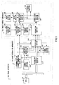
FIG.1 is a block diagram showing a configuration
of an image apparatus according to Embodiment 1 of the
present invention.
-
In FIG.1, image apparatus 100 is mainly constructed
of MPU 101, image generation apparatus 110 and image
display apparatus 120.
-
Image generation apparatus 110 is mainly
constructed of system bus interface section 111,
synchronization signal generation section 112, image data
generation section 113, selection section 114, signal
storage section 115 and power control section 116.
-
Image display apparatus 120 is mainly constructed
of separation section 121, display control section 122,
timing signal generation section 123, timing signal
selection 124, image data writing section 125, storage
section 126, image data reading section 127, drive section
128 and image display section 129.
-
When coded image data output from MPU 101 is
displayed, system bus interface section 111 outputs an
instruction for generating a synchronization signal to
synchronization signal generation section 112 and outputs
a signal output instruction for decoding and outputting
coded image data to image data generation section 113.
Furthermore, system bus interface section 111 notifies
power supply section 116 whether synchronization signal
generation section 112 and image data generation section
113 are operating or not.
-
When an instruction for generating a
synchronization signal is output from system bus
interface section 111, synchronization signal generation
section 112 outputs an image synchronization signal
indicating the timing of transmitting image data to image
data generation section 113, selection section 114 and
timing signal selection section 124.
-
Image data generation section 113 decodes the coded
image data according to the signal output instruction
output from system bus interface section 111 and outputs
the decoded image data, a write signal (WR signal) which
is an instruction for writing image data to storage section
126 and a selection signal (CS signal) for selecting
storage section 126 to selection section 114.
-
When image data, a write signal and selection signal
are output from image data generation section 113,
selection section 114 outputs these signals to separation
section 121, and during a blanking period during which
none of these signals is output from image data generation
section 113, selection section 114 outputs a blanking
notification signal indicating the blanking period to
signal storage section 115, reads a control command stored
in signal storage section 115 and outputs the control
command to separation section 121.
-
Furthermore, selection section 114 generates an
identification signal (A0 signal) to identify whether
the output signal is image data or a control command and
outputs the identification signal to separation section
121.
-
Signal storage section 115 stores the control
command output from MPU 101 through system bus interface
section 111 and outputs the stored control command to
selection section 114 when a blanking notification signal
is output from selection 114.
-
Power control section 116 supplies power to
synchronization signal generation section 112 and image
data generation section 113 and stops power supplies to
synchronization signal generation section 112 and image
data generation section 113 when synchronization signal
generation section 112 and image data generation section
113 are not operating.
-
Separation section 121 identifies whether the
signal output from selection section 114 is image data
or a control command based on an identification signal
and when the signal output from selection section 114
is image data, separation section 121 outputs the image
data to image data writing section 125 and when the signal
output from selection section 114 is a control command,
separation section 121 outputs the control command to
display control section 122.
-
When the control command output from separation
section 121 is a command instructing image display
apparatus 120 to operate in synchronization with an image
synchronization signal supplied from the outside, display
control section 122 outputs an instruction for selecting
the external synchronization signal to timing signal
selection section 124.
-
Timing signal generation section 123 generates a
frame timing signal to control timing of driving image
display section 129 and outputs the frame timing signal
to timing signal selection section 124.
-
Timing signal selection section 124 outputs the
frame timing signal output from timing signal generation
section 123 to drive section 128.
-
Furthermore, timing signal selection section 124
outputs a read timing signal for controlling timing of
reading the image data stored in storage section 126 and
supplying the image data to drive section 128 to image
reading section 127 and outputs a write enable signal
indicating timing at which the image data can be written
to storage section 126 to image data writing section 125.
-
When an instruction for selecting an external
synchronization signal from display control section 122
is input, timing signal selection section 124 outputs
a frame timing signal synchronized with an image
synchronization signal input from the outside to drive
section 128 and outputs a read timing signal to image
reading section 127.
-
When a write enable signal is output from timing
signal selection section 124, image data writing section
125 outputs the image data output from separation section
121 to storage section 126.
-
Storage section 126 stores the image data output
from image data writing section 125 and outputs the image
data to image data reading section 127 on demand.
-
When a read timing signal is output from timing
signal selection section 124, image data reading section
127 reads the image data from storage section 126 according
to the timing indicated by the read timing signal and
outputs the image data to drive section 128.
-
Drive section 128 outputs the image data output from
image data reading section 127 to image display section
129 according to the timing of the frame timing signal
output from timing signal selection section 124.
-
Image display section 129 displays the image data
output from drive section 128.
-
Next, an operation of image apparatus 100 will be
explained.
-
When image display apparatus 120 operates
independently, timing signal generation section 123
outputs a frame timing signal for controlling the timing
of driving image display section 129 to drive section
128 through timing signal selection section 124.
-
Furthermore, timing signal generation section 123
outputs a read timing signal indicating timing of reading
the image data stored in storage section 126 to image
data reading section 127 at timing synchronized with the
frame timing signal.
-
The image data is output from storage section 126
to drive section 128 through image data reading section
127 according to the timing of the read timing signal,
output to image display section 129 at timing synchronized
with the frame timing signal and displayed as an image
on image display section 129.
-
Thus, the image apparatus of Embodiment 1 displays
image data of storage section 126 using a frame timing
signal generated at timing signal generation section 123,
and can thereby autonomously display an image even if
no image synchronization signal or image data is supplied
from the outside.
-
When image data supplied from image generation
apparatus 110 is displayed on image display section 129,
coded image data output from MPU 101 is output to image
data generation section 113 through system bus interface
section 111.
-
Furthermore, an instruction signal for generating
an image synchronization signal is output to
synchronization signal generation section 112 based on
a control command output from MPU 101 and an instruction
signal for outputting image data is output to image data
generation section 113 (the control command is output
to signal storage section 115).
-
According to an instruction signal output from
system bus interface section 111, an image
synchronization signal is generated at synchronization
signal generation section 112 and output to image data
generation section 113, selection section 114 and timing
signal selection section 124.
-
Image data is generated by image data generation
section 113 decoding coded image data and written in
storage section 126 through selection section 114,
separation section 121 and image data writing section
125 in synchronization with an image synchronization
signal output from synchronization signal generation
section 112.
-
On the other hand, the image synchronization signal
output from synchronization signal generation section
112 is output to drive section 128 through timing signal
selection section 124.
-
Furthermore, a read timing signal indicating timing
of reading the image data stored in storage section 126
is output to image data reading section 127 at timing
synchronized with the frame timing signal.
-
The image data is output from storage section 126
to drive section 128 through image data reading section
127 according to timing of the read timing signal, output
to image display section 129 at timing synchronized with
the frame timing signal and displayed as an image on image
display section 129.
-
Thus, when the image synchronization signal and
image data are output to the above-described image display
apparatus, the image apparatus of Embodiment 1
synchronizes the timing of writing image data to the
storing means with the drive timing, and can thereby
display moving images without disturbance of a display
and provide a high definition image display.
-
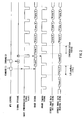
FIG.2 shows a signal timing chart of the image
apparatus according to Embodiment 1.
-
In FIG.2, the horizontal axis indicates the time.
-
When image display apparatus 120 operates
independently, image display apparatus 120 reads the
image data stored in storage section 126 in
synchronization with the frame timing signal output from
timing signal generation section 123.
-
When an independent operation of image display
apparatus 120 is switched to an operation of displaying
an image from the outside, a command (1) for instructing
generation and output of image data and an image
synchronization signal is output from MPU 101 to system
bus interface section 111.
-
According to command (1), synchronization signal
generation section 112 generates an image synchronization
signal (Vsync) and outputs to image data generation
section 113, selection section 114 and timing signal
selection section 124.
-
Furthermore, image data is generated by image data
generation section 113 in synchronization with the image
synchronization signal output from synchronization
signal generation section 112 and output to selection
section 114.
-
Then, MPU 101 outputs command (2) for instructing
image display apparatus 120 to operate in synchronization
with an image synchronization signal supplied from the
outside and when system bus interface section 111 decides
that command (2) is a command related to control over
image display apparatus 120, system bus interface section
111 writes command (2) to signal storage section 115.
-
Command ( 2 ) is read from signal storage section 115
during a period during which no image data is sent from
selection section 114 and output to separation section
121.
-
Then, command (2) is judged to be a control signal
by separation section 121 and output to timing signal
selection section 124 through display control section
122.
-
Writing to this signal storage section 115 is
performed with a data signal, selection signal (CS signal)
and write signal (WR signal).
-
Upon reception of command (2), timing signal
selection section 124 outputs the frame timing signal
output from timing signal generation section 123 and then
changes the frame timing signal to be output to the signal
output from synchronization signal generation section
112.
-
Thereafter, image data is written/read to/from
storage section 126 in synchronization with the frame
timing signal output from synchronization signal
generation section 112.
-
After receiving command (2), image display
apparatus 120 generates a frame timing signal
synchronized with the image synchronization signal
(Vsync) after a synchronization period and operates
reading and writing of the image data from/to storage
section 126 in synchronization with the image
synchronization signal (Vsync).
-
FIG.2 shows an example where command (2) issued by
MPU 101 to image display apparatus 120 is multiplexed
with a vertical blanking period of the vertical
synchronization signal (Vsync) and transferred to image
display apparatus 120, but command (2) may also be
multiplexed with the horizontal blanking period of a
horizontal synchronization signal (Hsync).
-
FIG.3 is another signal timing chart of the image
apparatus according to Embodiment 1.
-
In FIG.3, command (2) of MPU 101 is output during
a horizontal blanking period of horizontal
synchronization signal (Hsync) 301.
-
The image apparatus of Embodiment 1 uses the vertical
synchronization signal (Vsync) and horizontal
synchronization signal (Hsync) shown in FIG.3 as the image
synchronization signals generated by the image generation
apparatus and supplied to the image display apparatus,
but even if these signals are a vertical synchronization
signal (Vsync) and a valid data signal (VALID) as shown
in FIG.4, similar effects can be obtained.
-
Thus, according to the image apparatus 1 of
Embodiment 1, when the above-described image display
apparatus displays image data independently by displaying
the image data stored inside at timing of an internally
generated synchronization signal, the image generation
apparatus need not operate components such as the decoding
means and image synchronization signal generating means,
and can thereby reduce power consumption.
-
Furthermore, the image apparatus of Embodiment 1
sends a control command and image data through a common
signal line using a control signal distinguishing a
control command from image data, and can thereby display
images with fewer signal lines.
-
Furthermore, when an image synchronization signal
and image data are input from the outside to the image
display apparatus, the image apparatus of Embodiment 1
synchronizes the timing of writing the image data to
storage section 126 and the timing of driving image display
section 129, and can thereby display moving images without
disturbance of a display such as displaying an image being
rewritten.
-
Furthermore, the image apparatus of Embodiment 1
does not directly connect the MPU to the image display
apparatus and can perform control with fewer signal lines
by transferring a control command from the MPU to the
image display apparatus.
(Embodiment 2)
-
An image apparatus of Embodiment 2 performs control
and transfer of image data with the MPU connected to the
image display apparatus.
-
FIG.5 is a block diagram showing a configuration
example of the image apparatus according to Embodiment
2. However, components common to those in FIG.1 are
assigned the same reference numerals and detailed
explanations thereof will be omitted.
-
In FIG.5, MPU 101 is connected to separation section
121 through a system bus controlled by MPU 101.
-
This system bus connects image data through a data
bus, a CS signal through one selection signal, a WR signal
through a write signal and an A0 signal through one address
bus, respectively, and MPU 101 can thereby control the
A0 signal at a logical level by accessing a predetermined
address and can supply a control command and image data
to image display apparatus 120.
-
Thus, the image apparatus of this Embodiment 2 can
perform control and transfer of image data with the MPU
directly connected to the image display apparatus,
configure various electronic apparatuses irrespective
of whether or not to display moving images of image data,
eliminates the need to change the image display apparatus
for each electronic apparatus and thereby reduce the costs
of the electronic apparatus.
-
Furthermore, the image apparatus of this Embodiment
2 can use an image display apparatus in the same
configuration for the image display section irrespective
of the type of an image displayed.
-
The image apparatus of this Embodiment 2 connects
the CS signal to selection signal CS0 of the system bus
and the A0 signal to Address 0 of the address bus of the
system bus, but it is also possible to connect the CS
signal to an arbitrary selection signal and A0 signal
to any one address bus.
-
Furthermore, the image apparatus of this Embodiment
2 uses data, a CS signal and a WR signal as the interface
between the MPU or image generation apparatus and image
display apparatus, but similar effects can also be
achieved using data, a CS signal and read/write
identification signal (R/W signal) as the interface.
(Embodiment 3)
-
FIG.6 is a block diagram showing a configuration
example of an image apparatus according to Embodiment
3. However, the components common to those in FIG.1 are
assigned the same reference numerals as those in FIG.1
and detailed explanations thereof will be omitted.
-
The image apparatus in FIG.6 is different from FIG.1
in that the image apparatus in FIG.6 is equipped with
storage section 601 and performs writing and reading of
image data simultaneously.
-
In FIG.6, when a write enable signal is output from
timing signal selection section 124, image data writing
section 125 outputs image data output from separation
section 121 to storage section 601.
-
Storage section 601 stores the image data output
from image data writing section 125 and outputs the image
data to image data reading section 127 on demand.
Furthermore, storage section 601 has a dual port
configuration with reading and writing signal lines
provided separately and performs writing and reading of
image data simultaneously.
-
When a read timing signal is output from timing
signal selection section 124, image data reading section
127 reads image data from storage section 601 according
to the timing indicated by the read timing signal and
outputs to drive section 128.
-
Having a dual port configuration with reading and
writing signal lines provided separately, the image
apparatus of Embodiment 3 can write and read image data
simultaneously and thereby reduce the operating clock
rate.
(Embodiment 4)
-
FIG.7 is a block diagram showing a configuration
example of an image apparatus according to Embodiment
4. However, the components common to those in FIG.1 are
assigned the same reference numerals as those in FIG.1
and detailed explanations thereof will be omitted.
-
The image apparatus in FIG.7 is different from FIG. 1
in that it is equipped with system bus interface section
701 including flag 702 and MPU 101 references flag 702
and outputs a control command to selection section 114
during a period during which MPU 101 can output the control
command.
-
In FIG.7, system bus interface section 701 is
provided with flag 702, which is readable from MPU 101
through the system bus.
-
When selection section 114 selects a signal from
system bus interface section 701 and outputs to separation
section 121, selection section 114 sets flag 702 in such
a way as to indicate that transmission of a control command
is enabled, and when selection section 114 selects a signal
from image data generation section 113 and outputs to
separation section 121, selection section 114 sets flag
702 in such a way as to indicate that transmission of
a control command is disabled.
-
MPU 101 references flag 702 and issues a control
command to image generation apparatus 110 only when flag
702 is enabled.
-
Using the flag indicating whether it is possible
to issue a control command or not, the image apparatus
of Embodiment 4 can send, when a control command is input
from an external processing apparatus, the control
command to the image display apparatus during a period
during which no image data is sent, which eliminates the
need to store the control command and makes it possible
to reduce the circuit configuration.
(Embodiment 5)
-
FIG.8 is a block diagram showing a configuration
example of an image apparatus according to Embodiment
5. However, the components common to those in FIG.1 are
assigned the same reference numerals as those in FIG.1
and detailed explanations thereof will be omitted.
-
The image apparatus in FIG.8 is different from FIG.1
in that it is equipped with interrupt signal generation
section 801 and outputs an interrupt signal indicating
that it is possible to issue a control command to the
MPU.
-
In FIG.8, interrupt signal generation section 801
generates an interrupt signal at the beginning of a period
during which selection section 114 selects system bus
interface section 111 and outputs the interrupt signal
to MPU 101.
-
For example, when there is no image synchronization
signal input, selection section 114 always selects system
bus interface section 111 and sets a blanking notification
signal to be output to interrupt signal generation section
801 to "Low" and when an image synchronization signal
and image data are input, selection section 114 sets the
blanking notification signal to "Low" during only a period
during which selection section 114 selects system bus
interface section 111. Then, interrupt signal
generation section 801 generates an interrupt signal when
the blanking notification signal is changed from "High"
to "Low".
-
Here, since MPU 101 controls the operation of
synchronization signal generation section 112, MPU 101
can recognize whether an image synchronization signal
is generated or not and when no image synchronization
signal is generated, MPU 101 issues a control command
at arbitrary timing and when an image synchronization
signal is generated, MPU 101 issues a control command
within a predetermined time determined by the blanking
period of the image synchronization signal immediately
after an interrupt signal is received.
-
By outputting an interrupt signal indicating that
it is possible to issue a control command to an external
processing apparatus, the image apparatus of Embodiment
5 can send, when a control command is input from an external
processing apparatus, the control command to the image
display apparatus during a period during which no image
data is sent, which eliminates the need to store the control
command and makes it possible to reduce the circuit
configuration.
(Embodiment 6)
-
FIG.9 is a block diagram showing a configuration
example of an image apparatus according to Embodiment
6. However, the components common to those in FIG.1 are
assigned the same reference numerals as those in FIG.1
and detailed explanations thereof will be omitted.
-
The image apparatus in FIG.9 sends a control command
and an argument of the control command through a common
signal line using a control signal, which distinguishes
the control command and the argument of the control command.
Here, the argument refers to a parameter value to be passed
to the image display apparatus together with the control
command. The image display apparatus carries out
processing according to the control command and this
argument. For example, specifying an address at which
image data is written to or read from storage section
126 makes it possible to scroll the image displayed.
-
In FIG.9, system bus interface section 901 writes
one bit of the address bus of the system bus to signal
storage section 903 as an identification signal (A0
signal).
-
Selection section 902 reads a data signal and A0
signal from signal storage section 903 during a blanking
period during which no image data is output to separation
section 121.
-
Signal storage section 903 stores not only a data
signal input from system bus interface section 901 but
also an A0 signal and when selection section 902 selects
signal storage section 903, selection section 902 outputs
the data signal stored as a control command or an argument
of the control command together with the A0 signal to
separation section 121.
-
Thus , the image apparatus of this Embodiment 6 sends
a control command and an argument of the control command
through a common signal line using a control signal, which
distinguishes the control command and the argument of
the control command, and can thereby perform high-level
control with fewer signal lines.
(Embodiment 7)
-
FIG.10 is a block diagram showing a configuration
example of an image apparatus according to Embodiment
7. However, the components common to those in FIG.1 are
assigned the same reference numerals as those in FIG.1
and detailed explanations thereof will be omitted.
-
The image apparatus in FIG.10 is different from FIG. 1
in that it is provided with graphic data storage section
1001 and combination section 1002, and selects image data
and graphic data or combines these data with weights
assigned thereto.
-
In FIG.10, graphic data storage section 1001 stores
graphic data and a selector control signal output from
system bus interface section 111 and outputs the graphic
data and control signal to combination section 1002 in
synchronization with an image synchronization signal
output from synchronization signal generation section
112.
-
Combination section 1002 combines the image data
output from image data generation section 113 and graphic
data output from graphic data storage section 1001 and
outputs the combined image data to selection section 114.
-
Then, an example of the combination section will
be explained.
-
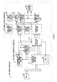
FIG.11 is a block diagram showing an example of the
combination section of the image generation apparatus
according to this Embodiment 7.
-
Combination section 1100 in FIG.11 is an image
combination apparatus operating as combination section
1002 of the image generation apparatus according to
Embodiment 7.
-
Selector 1101 selects either graphic data output
from system bus interface section 111 or image data output
from image data generation section 113 according to a
selector control signal output from system bus interface
section 111 and outputs to selection section 114.
-
Thus, by selecting and outputting either image data
or graphic data, the image generation apparatus according
to Embodiment 7 can improve power of expression of
displayed images.
-
For example, using one bit of data output from system
bus interface section 111, MPU 101 controls the selection
of images to be displayed and can thereby perform a display
in such a way as to overwrite the graphic data to be written
in graphic data storage section 1001 at any position of
the image data.
-
Then, another example of the combination section
will be explained.
-
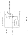
FIG.12 illustrates another example of the
combination section of the image generation apparatus
according to Embodiment 7.
-
Combination section 1200 in FIG.12 is an image
combination apparatus operating as combination section
1002 of the image generation apparatus according to
Embodiment 7.
-
In FIG.12, combination section 1200 is mainly
constructed of coefficient table 1201, multiplier 1202,
multiplier 1203 and adder 1204. Combination section 1200
combines graphic data output from system bus interface
section 111 and image data output from image data
generation section 113 with predetermined weights
assigned thereto and outputs the combined data to
selection section 114.
-
Coefficient table 1201 determines a combination
ratio between the graphic data and image data based on
a coefficient table signal output from system bus
interface section 111, outputs the weighting factor of
the image data in image combination to multiplier 1202
and outputs the weighting factor of the graphic data in
image combination to multiplier 1203.
-
Multiplier 1202 multiplies the image data by the
weighting factor output from coefficient table 1201 and
outputs the multiplication result to adder 1204.
-
Multiplier 1203 multiplies the graphic data by the
weighting factor output from coefficient table 1201 and
outputs the multiplication result to adder 1204.
-
Adder 1204 adds up the multiplication result output
from multiplier 1202 and the multiplication result output
from multiplier 1203 and outputs the addition result to
selection section 114 as the combined image data.
-
Thus, the image generation apparatus of Embodiment
7 can improve power of expression of displayed images
by combining image data and graphic data with weights
assigned thereto.
-
For example, graphic data can be transmitted to or
displayed at any position of image data using combination
section 1200.
(Embodiment 8)
-
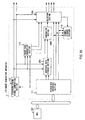
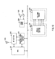
FIG.13 is a block diagram showing a configuration
example of a communication apparatus according to
Embodiment 8. The communication apparatus in FIG.13 is
mainly constructed of antenna 1301, RF section 1302,
baseband signal processing section 1303, voice CODEC
section 1304, receiver 1305, microphone 1306, MPEG-4
decoder section 1307, LCD panel module 1308 and MPU 101.
-
In FIG.13, antenna 1301 receives a radio signal and
outputs the received signal to RF section 1302 and
transmits a transmit signal output from RF section 1302.
-
RF section 1302 down-coverts the received signal
output from antenna 1301 to a baseband frequency, outputs
to baseband signal processing section 1303 and
up-converts the transmit signal output from baseband
signal processing section 1303 to a radio frequency and
outputs to antenna 1301.
-
Baseband signal processing section 1303 demodulates
the received signal output from RF section 1302, outputs
to MPU 101 and modulates the transmit signal output from
MPU 101 and outputs to RF section 1302.
-
When the received signal output from baseband signal
processing section 1303 is voice coded data, MPU 101
outputs the voice coded data to voice CODEC section 1304,
and when the received signal is image coded data, MPU
101 outputs the image coded data to MPEG-4 decoder section
1307. MPU 101 outputs the voice coded signal output from
voice CODEC section 1304 to baseband signal processing
section 1303 as a transmit signal.
-
Voice CODEC section 1304 decodes the voice coded
data output from MPU 101 and outputs the voice signal
obtained to receiver 1305, codes a voice signal output
from microphone 1306 and outputs the voice coded signal
obtained to MPU 101.
-
Receiver 1305 outputs the voice signal output from
voice CODEC section 1304 as voice.
-
Microphone 1306 receives voice and outputs the voice
signal to voice CODEC section 1304.
-
MPEG-4 decoder section 1307 decodes the image coded
data output from MPU 101, generates image data and outputs
the image data together with an image synchronization
signal to LCD panel module 1308.
-
LCD panel module 1308 displays moving images of the
decoded image data.
-
Then, an operation of the communication apparatus
according to Embodiment 8 will be explained.
-
A received signal is output to MPU 101 through
antenna 1301, RF section 1302 and baseband signal
processing section 1303.
-
When the received signal is image coded data, MPU
101 outputs the image coded data to MPEG-4 decoder section
1307, MPEG-4 decoder section 1307 decodes the image coded
data and generates image data, outputs the image data
together with an image synchronization signal to LCD panel
module 1308, and LCD panel module 1308 displays moving
images of the image data.
-
On the other hand, when the received signal is voice
coded data, MPU 101 outputs the voice coded data to voice
CODEC section 1304, voice CODEC section 1304 generates
a voice signal from the voice coded data and outputs to
receiver 1305. A voice signal input from microphone 1306
is coded by voice CODEC section 1304 and sent through
baseband signal processing section 1303, RF section 1302
and antenna 1301.
-
When the communication apparatus according to
Embodiment 8 displays no moving image of image data, MPU
101 can control LCD panel module 1308 through MPEG-4
decoder section 1307, and can thereby display graphics,
etc. on LCD panel module 1308. Furthermore, by stopping
a power supply to the part inside MPEG-4 decoder section
1307 that decodes image coded data, it is possible to
reduce power consumption of the cellular phone.
-
Thus, the communication apparatus of Embodiment 8
uses an interface that controls external signals to
transfer image data and control commands to the image
display apparatus through a common signal line, and can
thereby reduce the number of signal lines and reduce the
size of the communication apparatus.
-
Furthermore, the communication apparatus of
Embodiment 8 adds up image data and graphic data with
weights assigned thereto and displays the addition result,
and can thereby improve power of expression.
-
Furthermore, the communication apparatus of
Embodiment 8 stops a power supply to a part of the image
data generation section, and can thereby reduce power
consumption when there is no need to generate image data.
-
For example, it is possible to control LCD panel
module 1308 from MPU 101 without directly connecting MPU
101 and LCD panel module 1308.
-
Furthermore, using a common signal line to supply
image data and control commands to LCD panel module 1308
makes it possible to reduce the number of signal lines
and makes it easier to design the circuit board of the
communication apparatus and reduce the size of the
communication apparatus.
(Embodiment 9)
-
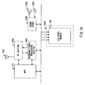
FIG.14 is a block diagram showing a configuration
example of a communication apparatus according to
Embodiment 9 of the present invention. However,
components common to those in FIG.13 are assigned the
same reference numerals and detailed explanations thereof
will be omitted.
-
The communication apparatus in FIG.14 is mainly
constructed of antenna 1301, RF section 1302, baseband
signal processing section 1303, voice CODEC section 1304,
receiver 1305, microphone 1306, LCD panel module 1308
and MPU 101.
-
Then, an operation of the communication apparatus
according to Embodiment 9 will be explained.
-
A received signal is output to MPU 101 through
antenna 1301, RF section 1302 and baseband signal
processing section 1303.
-
MPU 101 outputs the received signal to voice CODEC
section 1304, voice CODEC section 1304 generates a voice
signal from the received signal and outputs to receiver
1305. A voice signal input from microphone 1306 is coded
by voice CODEC section 1304 and sent through baseband
signal processing section 1303, RF section 1302 and
antenna 1301.
-
Furthermore, MPU 101 can control LCD panel module
1308 to display graphics, etc. on LCD panel module 1308,
for example.
-
In such a configuration, it is possible to directly
connect image display apparatus 120 made up of LCD panel
module 1308 to the system bus of MPU 101 to control the
image display apparatus 120 from MPU 101. The
communication apparatuses according to Embodiment 8 and
Embodiment 9 can use image display apparatus 120 made
up of common LCD panel module 1308 for individual cellular
phones having different functions, for example, with or
without functions of displaying moving images of image
data, and thereby contribute to a cost reduction compared
to a case where different LCD modules are used for different
types of apparatus.
-
Thus, the communication apparatus of Embodiment 9
can perform control and transfer image data with the MPU
connected to the image display apparatus.
-
The image apparatus of the present invention is
applicable to a mobile station apparatus in a mobile
communication system such as a cellular phone, portable
television telephone and a communication terminal
equipped with computer functions, or a stationary type
telephone set or television telephone set connected by
a cable line, or television receiver, computer or
information terminal apparatus having computer functions,
etc.
-
In this case, by transferring image data and control
commands to the image display apparatus through a common
signal line using an interface that controls external
signals, it is possible to reduce the number of signal
lines and reduce the size of the electronic device.
-
As is apparent from the above-described
explanations, by storing image data, displaying images
corresponding to the image data using a synchronization
signal generated inside the apparatus, stopping power
supplies to parts of the apparatus which are not operating,
selecting, when image data and a synchronization signal
are input from the outside, the externally input image
data and synchronization signal and displaying images,
it is possible to display images of the pre-stored image
data and external images in a configuration with low power
consumption, a small circuit scale and high versatility.
-
This application is based on the Japanese Patent
Application No.2000-285792 filed on September 20, 2000,
entire content of which is expressly incorporated by
reference herein.
Industrial Applicability
-
The present invention is ideally applicable to an
image apparatus and a communication apparatus that
displays images.