EP1319996A2 - Detoning blade - Google Patents
Detoning blade Download PDFInfo
- Publication number
- EP1319996A2 EP1319996A2 EP02258467A EP02258467A EP1319996A2 EP 1319996 A2 EP1319996 A2 EP 1319996A2 EP 02258467 A EP02258467 A EP 02258467A EP 02258467 A EP02258467 A EP 02258467A EP 1319996 A2 EP1319996 A2 EP 1319996A2
- Authority
- EP
- European Patent Office
- Prior art keywords
- detoning
- blade
- coating
- roller
- microns
- Prior art date
- Legal status (The legal status is an assumption and is not a legal conclusion. Google has not performed a legal analysis and makes no representation as to the accuracy of the status listed.)
- Granted
Links
Images


Classifications
-
- G—PHYSICS
- G03—PHOTOGRAPHY; CINEMATOGRAPHY; ANALOGOUS TECHNIQUES USING WAVES OTHER THAN OPTICAL WAVES; ELECTROGRAPHY; HOLOGRAPHY
- G03G—ELECTROGRAPHY; ELECTROPHOTOGRAPHY; MAGNETOGRAPHY
- G03G21/00—Arrangements not provided for by groups G03G13/00 - G03G19/00, e.g. cleaning, elimination of residual charge
- G03G21/0005—Arrangements not provided for by groups G03G13/00 - G03G19/00, e.g. cleaning, elimination of residual charge for removing solid developer or debris from the electrographic recording medium
- G03G21/0035—Arrangements not provided for by groups G03G13/00 - G03G19/00, e.g. cleaning, elimination of residual charge for removing solid developer or debris from the electrographic recording medium using a brush; Details of cleaning brushes, e.g. fibre density
-
- G—PHYSICS
- G03—PHOTOGRAPHY; CINEMATOGRAPHY; ANALOGOUS TECHNIQUES USING WAVES OTHER THAN OPTICAL WAVES; ELECTROGRAPHY; HOLOGRAPHY
- G03G—ELECTROGRAPHY; ELECTROPHOTOGRAPHY; MAGNETOGRAPHY
- G03G21/00—Arrangements not provided for by groups G03G13/00 - G03G19/00, e.g. cleaning, elimination of residual charge
- G03G21/0005—Arrangements not provided for by groups G03G13/00 - G03G19/00, e.g. cleaning, elimination of residual charge for removing solid developer or debris from the electrographic recording medium
- G03G21/0011—Arrangements not provided for by groups G03G13/00 - G03G19/00, e.g. cleaning, elimination of residual charge for removing solid developer or debris from the electrographic recording medium using a blade; Details of cleaning blades, e.g. blade shape, layer forming
- G03G21/0017—Details relating to the internal structure or chemical composition of the blades
-
- Y—GENERAL TAGGING OF NEW TECHNOLOGICAL DEVELOPMENTS; GENERAL TAGGING OF CROSS-SECTIONAL TECHNOLOGIES SPANNING OVER SEVERAL SECTIONS OF THE IPC; TECHNICAL SUBJECTS COVERED BY FORMER USPC CROSS-REFERENCE ART COLLECTIONS [XRACs] AND DIGESTS
- Y10—TECHNICAL SUBJECTS COVERED BY FORMER USPC
- Y10T—TECHNICAL SUBJECTS COVERED BY FORMER US CLASSIFICATION
- Y10T428/00—Stock material or miscellaneous articles
- Y10T428/12—All metal or with adjacent metals
- Y10T428/12493—Composite; i.e., plural, adjacent, spatially distinct metal components [e.g., layers, joint, etc.]
- Y10T428/12771—Transition metal-base component
- Y10T428/12861—Group VIII or IB metal-base component
- Y10T428/12951—Fe-base component
- Y10T428/12972—Containing 0.01-1.7% carbon [i.e., steel]
-
- Y—GENERAL TAGGING OF NEW TECHNOLOGICAL DEVELOPMENTS; GENERAL TAGGING OF CROSS-SECTIONAL TECHNOLOGIES SPANNING OVER SEVERAL SECTIONS OF THE IPC; TECHNICAL SUBJECTS COVERED BY FORMER USPC CROSS-REFERENCE ART COLLECTIONS [XRACs] AND DIGESTS
- Y10—TECHNICAL SUBJECTS COVERED BY FORMER USPC
- Y10T—TECHNICAL SUBJECTS COVERED BY FORMER US CLASSIFICATION
- Y10T428/00—Stock material or miscellaneous articles
- Y10T428/12—All metal or with adjacent metals
- Y10T428/12493—Composite; i.e., plural, adjacent, spatially distinct metal components [e.g., layers, joint, etc.]
- Y10T428/12771—Transition metal-base component
- Y10T428/12861—Group VIII or IB metal-base component
- Y10T428/12951—Fe-base component
- Y10T428/12972—Containing 0.01-1.7% carbon [i.e., steel]
- Y10T428/12979—Containing more than 10% nonferrous elements [e.g., high alloy, stainless]
Definitions
- This invention relates generally to a cleaning apparatus in a printing or copying apparatus, and more particularly to a detoning blade for cleaning a roller therein.
- cleaning systems, detoning systems and blades can be found in US-A-3,572,923; US-A-5,209,997; US-A-5,243,385; US-A-5,512,995; US-A-5,732,320; US-A-6,088,564; US-A-6,134,405; US-A-6,263,180; and US-A-6,282,401.
- a detoning blade comprising a steel member having a length, a width, and a thickness.
- a coating comprising titanium nitride is disposed on at least a portion of the steel member.
- the coating has a thickness ranging from 0.1 micron to 4 microns.
- the steel may be a carbon steel including grade 1095 or a stainless steel including grades 301 and 302.
- the surface hardness of the detoning blade may be up to 80 Rockwell C.
- a detoning blade comprising a steel member having a length, a width, and a thickness.
- a coating comprising tungsten carbide is disposed on at least a portion of the steel member.
- the coating has a thickness ranging from 0.1 micron to 4 microns.
- the steel may be a carbon steel including grade 1095 or a stainless steel including grades 301 and 302.
- the surface hardness of the detoning blade may be up to 68 Rockwell C.
- a detoning blade comprising a steel member having a length, a width, and a thickness.
- a coating comprising diamond embedded chromium is disposed on at least a portion of the steel member.
- the coating has a thickness ranging from 2.5 micron to 7.5 microns.
- the steel may be a carbon steel including grade 1095 or a stainless steel including grades 301 and 302.
- a method of making a detoning blade comprising: providing a steel member having a length up to 40 mm and a thickness up to about 100 microns; and applying a coating of titanium nitride or tungsten carbide having a thickness ranging from 0.1 micron to 4 microns on at least a portion of a surface of the steel member using physical vapor deposition or chemical vapor deposition at a temperature ranging from 70°F to 450°F (21°C to 232°C).
- the coating may include diamond embedded chromium (Armoloy XADC) having a thickness ranging from 2.5 microns to 7.5 microns using an Armoloy coating process at a temperature ranging from 70°F to 200°F (21°C to 93°C).
- the method may include providing a carbon steel including grade 1095 or a stainless steel including grades 301 and 302.
- an apparatus for removing particles from a surface of a roller comprising a housing, a roller, a detoning blade, and a detoning blade holder.
- the housing includes an open ended chamber.
- the roller is rotatably mounted in the housing.
- the detoning blade has a length, a width, a thickness, a free end and a fixed end. The free end contacts the roller.
- the detoning blade includes a steel and a coating of titanium nitride or tungsten carbide having a thickness ranging from 0.1 microns to 4 microns disposed on at least a portion of the steel.
- the coating may include diamond embedded chromium (Armoloy XADC) having a thickness ranging from 2.5 microns to 7.5 microns.
- the detoning blade holder is coupled to the housing on one end and coupled to the fixed end of the detoning blade on another end of the detoning blade holder with the free end of the detoning blade contacting the roller.
- the detoning blade may include a bevelled edge or a square edge in contact with the roller.
- the steel may include a carbon steel such as a grade 1095 and a stainless steel such as grades 301 and 302.
- a method for removing particles from a surface of a roller comprising: providing a roller having a surface; providing a detoning blade having a length, a width, a thickness, and a free end in contact with the roller, the detoning blade comprising a steel and a coating having a thickness ranging from .1 micron to 7.5 microns disposed on at least a portion of the member, the coating including titanium nitride, tungsten carbide, or diamond embedded chromium; supporting the detoning blade in a detoning blade holder; applying a force on the roller using the free end of the detoning blade; and rotating the roller and scraping toner from the surface.
- the method may include providing a carbon steel including grade 1095 or a stainless steel including grades 301 and 302.
- the method may include providing a bevelled edge or a square edge at the free end of the detoning blade having a bevelled edge in contact with the roller.
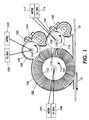
- the apparatus includes a fiber brush cleaning arrangement having dual detoning rollers for removing residual toner and debris from the image carrier 10.
- a fiber cleaning brush 100 is supported for rotational movement in the direction of the arrow 102 via motor 104, within a cleaning housing 106, and biased to clean the preferred polarity toner by means of a D.C. power source 108.
- a fiber brush may advantageously comprise a large number of conductive cleaning fibers 110 supported on a conductive cylindrical member 112.
- the housing 106 may be economically manufactured in a unitary extrusion, with recesses formed in accordance with component requirements. Residual toner and contaminants or debris such as paper fibers and Kaolin are removed from the photoreceptor belt 10 surface by means of a brushing action of the fibers 110 against belt 10 and the electrostatic charge applied to the fibers from the D.C. power supply 108.
- the biased detoning rollers are located in adjacent proximity to the biased brush 100 to enable the detoning rollers 114, 120 to electrostatically remove the toner particles from the brush fibers 110.
- the brush fibers 110 containing toner and debris removed from image carrier 10, rotating in the direction of arrow 12, are first contacted by a first detoning roller 114 supported for rotation in the direction of arrow 115, the same direction as brush 100, by means of a motor 117.
- An electrical bias is supplied to first detoning roller 114 from D.C. power supply 116.
- the detoning roller 114 is supported in a rotational position against brush 100, closely spaced to the position where brush fibers 110 leave contact with the surface of image carrier such as photoreceptor belt 10.
- a second detoning roller 120 is provided for further removal of the preponderance of residual toner from the brush at a location spaced along the circumference of the brush 100.
- a motor 122 drives the detoning roller 120 in the direction of the arrow 124, the same direction as fiber brush 100 and roller 114.
- An electrical bias is supplied to the detoning roller 120 from a D.C. power source 123.
- Recesses 130 and 132 in cleaning housing 106 are provided for the support of the detoning rollers 114 and 120, respectively therein. Within these recesses, and removed from cleaning brush 100, are located detoning blades 140, 150 for the detoning rollers 114, 120, respectively.
- the detoning blades 140, 150 remove the toner and debris particles from the surface of the detoning rolls 114,120 by a chiselling or scraping action when the blades 140, 150 are in the doctoring mode, as shown in FIG. 1.
- the detoning blades can also remove the toner and debris particles from the detoning rollers by a wiping action, if the detoning blades are in the wiper mode.
- the detoning blade is a metal material which may include stainless steel, aluminum, phosphor bronze, beryllium-copper, and carbon steel. The removed toner and debris particles fall into the auger arrangements and are transported to a storage area or to a developing station.
- the extension length (L) is the length of the detoning blade extending from the blade holder 145, 155 to the free end of the detoning blade.
- the length (L) ranges from 3 mm to 40 mm.
- the thickness (T) is the thickness of the blade including coating and ranges from 0.04 mm to 0.1 mm, generally about 0.06-0.08 mm.
- the width (W) is the width of the blade and ranges from about 420 mm for "long edge feed” and 240 mm for "short edge feed” (A "short edge feed” is when 8-1/2 in. X 14 in.
- (216 x 356mm) paper is fed into the copier by it's 8-1/2 in. (216mm) edge where the typical process width is 9 in. (229mm) to avoid edge effects.
- a "long edge feed” is where the paper is fed in by it's 14 in. (356mm) edge.).
- the blade holder is approximately 430 mm for long edge feed and 250 mm for short edge feed.
- FIG. 3 illustrates the free end of the blade frictionally contacting the detoning roller to clean particles or toner from the surface of the detoning roller.
- FIG. 4 illustrates an embodiment of a detoning blade with a bevelled free end frictionally contacting the roller.
- the bevelled edge may be ground to a desired angle e ranging from 30° to 45°, generally about 30°.
- the bevelling of the blade provides a wear surface and the coating provides a generally hard, low friction surface and finish.
- FIG. 5 illustrates an embodiment of a blade having a coated surface and a free end with a square edge for contact with the detoning roller.
- FIG. 6 illustrates an embodiment of a blade having a coated surface and a free end with a bevelled edge for contact with the detoning roller.
- the coatings of titanium nitride and tungsten carbide are commercially available from Balzers Tool Coating Inc., Amherst, NY, USA.
- the diamond embedded chromium coating (Armoloy XADC) is commercially available from Armoloy of Illinois, DeKalb, Illinois, 60115, USA.
- the thickness (T B ) is the thickness of the blade without coatings and ranges from 0.035 mm to 0.095 mm, generally about 0.055 mm.
- the thickness (T C ) of titanium nitride and tungsten carbide coatings ranges from 0.1 micron to 4 microns, generally about 2 microns.
- the thickness (T C ) of diamond embedded chromium coating ranges from 2.5 microns to 7.5 microns, generally about 4-5 microns.
- the titanium nitride and tungsten carbide coatings are disposed on the blade using a temperature of 21°C to 232°C (70°F to 450°F) physical vapor deposition (PVD) process or chemical vapor deposition (CVD) process, a substrate temperature 21°C to 232°C (70°F to 450°F) and a deposition pressure ranging from 0.05 torr to about 0.15 torr, generally about 0.05 torr.
- the Armoloy XADC coating is disposed on the blade using a temperature 21°C to 93°C (70°F to 200°F) Armoloy coating process.
- the low temperature PVD or CVD process of coating advantageously protects the blade against wear, abrasion and friction without deformation.
- the deposition of a hard thin-film coating advantageously extends the service life of the detoning blade providing an immediate benefit to users.
- the principal consideration for wear of blades is mechanical wear for stainless steel and mechanical wear and corrosion (rust) for carbon steel blades.
- a coating of Titanium Nitride on the blade having a thickness of 0.1-4 microns increases surface hardness of the blade to about 80 Rockwell C.
- a coating of Tungsten Carbide having a thickness of 0.1-4 microns increases surface hardness of the blade to about 68 Rockwell C.
- a coating of diamond embedded chromium having a thickness of 2.5-7.5 microns increases surface hardness of the blade to about 90 Rockwell C. Grinding and forming a bevelled edge and subsequent coating of a wear surface on a steel blade may increase the service life of detoning blades against highly abrasive rollers such as ceramic detoning rollers. The increased contact area of the bevelled coated blade may minimizes or eliminates roller to blade contact at the blade corners (stress concentration area) where the blade is most prone to wear.
- a detoning blade including a carbon steel or stainless steel member having a coating disposed thereon.
- the detoning blade has a length, a width, and a thickness.
- the coating may include titanium nitride or tungsten carbide of a thickness ranging from 0.1 microns to 4 microns or a coating of diamond embedded chromium coating (Armoloy XADC) of a thickness ranging from 2.5 microns to 7.5 microns on at least a portion of the steel member.
- the blade may include a free end having a bevelled edge forming a non-square corner on the free end of the detoning blade.
- the blade may include a free end having two square corners on the free end of the detoning blade.
- detoning blades, systems and methods of use advantageously overcome various limitations and provide generally low development and production costs, and generally high quality blades.
- the embodiments discussed above refer to a detoning blade and a detoning roller.
- the present invention can also be applied to a cleaning blade and a photoreceptive surface to reduce end wear of the photoreceptive drum or belt.
Landscapes
- Physics & Mathematics (AREA)
- General Physics & Mathematics (AREA)
- Cleaning In Electrography (AREA)
- Other Surface Treatments For Metallic Materials (AREA)
- Polishing Bodies And Polishing Tools (AREA)
- Nonmetal Cutting Devices (AREA)
- Physical Vapour Deposition (AREA)
Abstract
Description
Claims (9)
- A detoning blade (140,150) comprising:wherein the coating has a thickness ranging from 0.1 micron to 4 microns.a steel member having a length, a width, and a thickness; anda coating comprising at least one of titanium nitride and tungsten carbide on at least a portion of the steel member;
- A detoning blade according to claim 1, wherein the coating is titanium nitride and the surface hardness of the member is up to 80 Rockwell C.
- A detoning blade according to claim 2, wherein the coating is tungsten carbide and the surface hardness of the member is up to 68 Rockwell C.
- A detoning blade (140,150) comprising:wherein the coating has a thickness ranging from 2.5 microns to 7.5 microns and a surface hardness up to 90 Rockwell C.a steel member having a length, a width, and a thickness; and,a coating comprising diamond embedded chromium on at least a portion of the steel member;
- A detoning blade according to any one of the preceding claims, wherein the steel is at least one of carbon steel grade 1095, stainless steel grade 301, and stainless steel grade 302.
- A detoning blade according to any one of the preceding claims, wherein the blade further includes a free edge having a bevelled edge.
- A detoning blade according to any one of claims 1 to 5, wherein the blade further includes a free edge having two square corners.
- An apparatus for removing particles from a surface of a roller (114,120), comprising:a housing (132) defining an open ended chamber;a roller (114,120) rotatably mounted in said housing;a detoning blade (140,150) according to any one of the preceding claims having a free end and a fixed end, the free end being in contact with the roller (114,120), and,a detoning blade holder (145,155) coupled to the housing (132) on one end and coupled to the fixed end of the detoning blade on another end of the detoning blade holder, the free end of said detoning blade (140,150) contacting the roller (114,120).
- An apparatus according to claim 8, wherein the roller is a ceramic detoning roller (114,120).
Applications Claiming Priority (2)
| Application Number | Priority Date | Filing Date | Title |
|---|---|---|---|
| US15889 | 2001-12-17 | ||
| US10/015,889 US6633739B2 (en) | 2001-12-17 | 2001-12-17 | Detoning blade |
Publications (3)
| Publication Number | Publication Date |
|---|---|
| EP1319996A2 true EP1319996A2 (en) | 2003-06-18 |
| EP1319996A3 EP1319996A3 (en) | 2004-07-07 |
| EP1319996B1 EP1319996B1 (en) | 2007-01-31 |
Family
ID=21774194
Family Applications (1)
| Application Number | Title | Priority Date | Filing Date |
|---|---|---|---|
| EP02258467A Expired - Lifetime EP1319996B1 (en) | 2001-12-17 | 2002-12-09 | Detoning blade for cleaning a roller of a printing or copying apparatus |
Country Status (5)
| Country | Link |
|---|---|
| US (1) | US6633739B2 (en) |
| EP (1) | EP1319996B1 (en) |
| JP (1) | JP3905026B2 (en) |
| BR (1) | BR0204995A (en) |
| DE (1) | DE60217952T2 (en) |
Families Citing this family (13)
| Publication number | Priority date | Publication date | Assignee | Title |
|---|---|---|---|---|
| US20020098376A1 (en) * | 2000-10-20 | 2002-07-25 | Morris Harry C. | Friction guard blade and a method of production thereof |
| US7013104B2 (en) * | 2004-03-12 | 2006-03-14 | Lexmark International, Inc. | Toner regulating system having toner regulating member with metallic coating on flexible substrate |
| JP4483533B2 (en) * | 2004-11-04 | 2010-06-16 | コニカミノルタビジネステクノロジーズ株式会社 | Developing device and image forming apparatus |
| US8784946B2 (en) * | 2008-09-30 | 2014-07-22 | Xerox Corporation | Continuous manufacturing process for coated-core cleaner blades |
| US7962085B2 (en) * | 2009-10-15 | 2011-06-14 | Xerox Corporation | Metal blade cleaning of an amorphous silicon receptor |
| JP5532410B2 (en) * | 2010-03-18 | 2014-06-25 | 株式会社リコー | Cleaning device and image forming apparatus |
| BR112014030460A2 (en) * | 2012-06-26 | 2017-06-27 | Tega Ind Ltd | belt scraper assembly |
| DE102012106351B4 (en) * | 2012-07-13 | 2015-11-19 | C. & E. Fein Gmbh | Saw blade or cut-off blade made of martensitic stainless steel or steel and process for its production |
| JP5754422B2 (en) * | 2012-07-20 | 2015-07-29 | コニカミノルタ株式会社 | Cleaning device |
| JP6135558B2 (en) * | 2014-03-07 | 2017-05-31 | 富士ゼロックス株式会社 | Rubbing member for image forming apparatus, cleaning device, process cartridge, and image forming apparatus |
| US9469484B2 (en) * | 2014-12-12 | 2016-10-18 | Tega Industries Limited | Belt scraper assembly |
| JP6922184B2 (en) * | 2016-10-26 | 2021-08-18 | 富士フイルムビジネスイノベーション株式会社 | Cleaning blade and image forming device |
| JP2018205653A (en) * | 2017-06-09 | 2018-12-27 | コニカミノルタ株式会社 | Cleaning device, image formation apparatus, and manufacturing method for rigid body blade |
Family Cites Families (21)
| Publication number | Priority date | Publication date | Assignee | Title |
|---|---|---|---|---|
| US3572923A (en) | 1968-08-26 | 1971-03-30 | Xerox Corp | Cleaning method and apparatus for electrostatic copying machines |
| JPS5625960A (en) * | 1979-08-09 | 1981-03-12 | Mitsubishi Metal Corp | Surface-coated high speed steel material for cutting tool |
| US4633999A (en) * | 1985-08-30 | 1987-01-06 | Perneczky George C | Self-adjusting conveyor belt cleaning apparatus |
| US4653373A (en) * | 1986-01-08 | 1987-03-31 | Gerber Scientific Inc. | Knife blade and method for making same |
| JPH0692078B2 (en) * | 1988-12-15 | 1994-11-16 | 株式会社貝印刃物開発センター | Coated blade |
| US4970560A (en) * | 1988-12-22 | 1990-11-13 | Xerox Corporation | Lubricated metal cleaning blade for use in dry electrophotographic processes |
| JP2962843B2 (en) * | 1990-06-07 | 1999-10-12 | キヤノン株式会社 | Cleaning blade and device using the same |
| US5085171A (en) * | 1991-06-10 | 1992-02-04 | Lexmark International, Inc. | Compliant doctor blade |
| US5209997A (en) | 1991-11-18 | 1993-05-11 | Xerox Corporation | Three roll fuser |
| US5237375A (en) * | 1992-05-13 | 1993-08-17 | Steven Bruce Michlin | Wiper and spreader blade stiffener |
| US5243385A (en) | 1992-07-28 | 1993-09-07 | Xerox Corporation | Bowed support for belt photoreceptor to equalize blade cleaning contact pressure |
| US5512995A (en) | 1994-08-22 | 1996-04-30 | Xerox Corporation | Non-uniform scraper blade load to increase detoning roll life |
| US5652045A (en) * | 1994-10-20 | 1997-07-29 | Mitsubishi Materials Corporation | Coated tungsten carbide-based cemented carbide blade member |
| JP3443519B2 (en) * | 1996-09-30 | 2003-09-02 | 京セラ株式会社 | blade |
| US5732320A (en) | 1996-10-02 | 1998-03-24 | Xerox Corporation | Cleaning blade |
| US6134405A (en) | 1999-02-26 | 2000-10-17 | Xerox Corporation | Combined charging and cleaning blade |
| US6088564A (en) | 1999-08-13 | 2000-07-11 | Xerox Corporation | Translating tribocharging blade |
| US6282401B1 (en) | 1999-09-02 | 2001-08-28 | Xerox Corporation | Hard cleaning blade for cleaning an imaging member |
| US6263180B1 (en) | 1999-09-29 | 2001-07-17 | Xerox Corporation | Charge metering blade with polyurethane base and low surface energy coating thereon |
| EP1092535A1 (en) * | 1999-10-13 | 2001-04-18 | Think Laboratory Co., Ltd. | Doctor blade |
| KR100426843B1 (en) * | 2000-11-13 | 2004-04-13 | 박인순 | Method and apparatus for manufacturing cutting blades, and a cutting blade manufactured by the same |
-
2001
- 2001-12-17 US US10/015,889 patent/US6633739B2/en not_active Expired - Lifetime
-
2002
- 2002-12-09 EP EP02258467A patent/EP1319996B1/en not_active Expired - Lifetime
- 2002-12-09 DE DE60217952T patent/DE60217952T2/en not_active Expired - Lifetime
- 2002-12-09 BR BR0204995-3A patent/BR0204995A/en not_active Application Discontinuation
- 2002-12-10 JP JP2002357625A patent/JP3905026B2/en not_active Expired - Fee Related
Also Published As
| Publication number | Publication date |
|---|---|
| US6633739B2 (en) | 2003-10-14 |
| EP1319996A3 (en) | 2004-07-07 |
| JP2003202787A (en) | 2003-07-18 |
| DE60217952T2 (en) | 2007-10-25 |
| EP1319996B1 (en) | 2007-01-31 |
| BR0204995A (en) | 2004-06-29 |
| US20030113146A1 (en) | 2003-06-19 |
| DE60217952D1 (en) | 2007-03-22 |
| JP3905026B2 (en) | 2007-04-18 |
Similar Documents
| Publication | Publication Date | Title |
|---|---|---|
| EP1319996B1 (en) | Detoning blade for cleaning a roller of a printing or copying apparatus | |
| US5153654A (en) | Image forming apparatus having transfer member for carrying transfer material | |
| US6601991B2 (en) | Roller device for an image transferring device | |
| US11188003B2 (en) | Electrophotographic photoreceptor and image forming apparatus | |
| US6253044B1 (en) | Image forming apparatus having blade cleaning device applied thereto, and process cartridge | |
| US5512995A (en) | Non-uniform scraper blade load to increase detoning roll life | |
| EP0875801B1 (en) | Apparatus for developing a latent image and electrophotographic process | |
| JPH04352186A (en) | Cleaning blade | |
| US10649354B2 (en) | Electrophotographic photoreceptor and image forming apparatus | |
| JP4826385B2 (en) | Cleaning method | |
| JP4639865B2 (en) | Cleaning device and image forming apparatus using the same | |
| US7043187B2 (en) | Conductive fiber brush cleaner having brush speed control | |
| EP1588222A2 (en) | Remanufactured toner cartridge having modified roller section | |
| JP2008046365A (en) | Scraper, cleaning device and image forming apparatus | |
| EP0990958A3 (en) | Roller cleaning apparatus of liquid electrophotographic printer | |
| US6697599B2 (en) | Device for removing a coating adhering to an intermediate carrier in an electrophotographic printer or copier device | |
| JP5639491B2 (en) | Cleaning blade, cleaning blade manufacturing method, and toner regulating blade | |
| JP2002333805A (en) | Image forming method and image forming apparatus using electrophotography | |
| JP2006259274A (en) | Image forming apparatus and process cartridge | |
| JPH05119504A (en) | Image forming device | |
| JP2007086321A (en) | Lubricant application / cleaning unit, process cartridge, and image forming apparatus | |
| JP2006133428A (en) | Fixing apparatus and image forming apparatus | |
| JP2000010302A (en) | Function-reproducing organic photoreceptor substrate regeneration device for electrophotography | |
| JPH09251263A (en) | Solid lubricant coating apparatus and coating method, and image forming apparatus | |
| JP2004334119A (en) | Polishing method and polishing apparatus for electrophotographic photoreceptor |
Legal Events
| Date | Code | Title | Description |
|---|---|---|---|
| PUAI | Public reference made under article 153(3) epc to a published international application that has entered the european phase |
Free format text: ORIGINAL CODE: 0009012 |
|
| AK | Designated contracting states |
Designated state(s): AT BE BG CH CY CZ DE DK EE ES FI FR GB GR IE IT LI LU MC NL PT SE SI SK TR |
|
| AX | Request for extension of the european patent |
Extension state: AL LT LV MK RO |
|
| PUAL | Search report despatched |
Free format text: ORIGINAL CODE: 0009013 |
|
| AK | Designated contracting states |
Kind code of ref document: A3 Designated state(s): AT BE BG CH CY CZ DE DK EE ES FI FR GB GR IE IT LI LU MC NL PT SE SI SK TR |
|
| AX | Request for extension of the european patent |
Extension state: AL LT LV MK RO |
|
| 17P | Request for examination filed |
Effective date: 20050107 |
|
| AKX | Designation fees paid |
Designated state(s): DE FR GB |
|
| GRAP | Despatch of communication of intention to grant a patent |
Free format text: ORIGINAL CODE: EPIDOSNIGR1 |
|
| RTI1 | Title (correction) |
Free format text: DETONING BLADE FOR CLEANING A ROLLER OF A PRINTING OR COPYING APPARATUS |
|
| GRAS | Grant fee paid |
Free format text: ORIGINAL CODE: EPIDOSNIGR3 |
|
| GRAA | (expected) grant |
Free format text: ORIGINAL CODE: 0009210 |
|
| AK | Designated contracting states |
Kind code of ref document: B1 Designated state(s): DE FR GB |
|
| REG | Reference to a national code |
Ref country code: GB Ref legal event code: FG4D |
|
| REF | Corresponds to: |
Ref document number: 60217952 Country of ref document: DE Date of ref document: 20070322 Kind code of ref document: P |
|
| ET | Fr: translation filed | ||
| PLBE | No opposition filed within time limit |
Free format text: ORIGINAL CODE: 0009261 |
|
| STAA | Information on the status of an ep patent application or granted ep patent |
Free format text: STATUS: NO OPPOSITION FILED WITHIN TIME LIMIT |
|
| 26N | No opposition filed |
Effective date: 20071101 |
|
| REG | Reference to a national code |
Ref country code: FR Ref legal event code: PLFP Year of fee payment: 14 |
|
| REG | Reference to a national code |
Ref country code: FR Ref legal event code: PLFP Year of fee payment: 15 |
|
| PGFP | Annual fee paid to national office [announced via postgrant information from national office to epo] |
Ref country code: GB Payment date: 20161128 Year of fee payment: 15 Ref country code: FR Payment date: 20161121 Year of fee payment: 15 Ref country code: DE Payment date: 20161121 Year of fee payment: 15 |
|
| REG | Reference to a national code |
Ref country code: DE Ref legal event code: R119 Ref document number: 60217952 Country of ref document: DE |
|
| GBPC | Gb: european patent ceased through non-payment of renewal fee |
Effective date: 20171209 |
|
| REG | Reference to a national code |
Ref country code: FR Ref legal event code: ST Effective date: 20180831 |
|
| PG25 | Lapsed in a contracting state [announced via postgrant information from national office to epo] |
Ref country code: FR Free format text: LAPSE BECAUSE OF NON-PAYMENT OF DUE FEES Effective date: 20180102 Ref country code: DE Free format text: LAPSE BECAUSE OF NON-PAYMENT OF DUE FEES Effective date: 20180703 |
|
| PG25 | Lapsed in a contracting state [announced via postgrant information from national office to epo] |
Ref country code: GB Free format text: LAPSE BECAUSE OF NON-PAYMENT OF DUE FEES Effective date: 20171209 |