BACKGROUND OF THE INVENTION
The present invention relates to a magnet,
for example a magnetic assembly suited for magnetic
resonance imaging apparatus, and more particularly to a
homogeneous magnetic field generating apparatus having
an open type magnet with a particularly wide opening.
A magnetic resonance imaging apparatus
(hereinafter referred to as an MRI apparatus) produces
an image showing physical and chemical properties of a
subject under inspection by utilizing a nuclear
magnetic resonance phenomenon that occurs when the
subject placed in a homogeneous static magnetic field
is irradiated with an electromagnetic wave. The MRI
apparatus is used particularly for medical treatments.
The MRI apparatus mainly includes a static
magnetic field generating unit to apply a homogeneous
static magnetic field in an imaging volume, an RF coil
system to transmit and receive an electromagnetic wave,
and a gradient magnetic field generating unit to apply
a gradient magnetic field that gives position
information on a resonant phenomenon.
The MRI apparatus can be divided into two
general categories mainly in terms of a magnetic field
application method. One is a horizontal magnetic field
apparatus in which an imaging volume is placed in an
internal space of a group of coils arranged coaxially
in multiple layers, and the other is a vertical
magnetic field apparatus (open type) in which an
imaging volume is sandwiched between opposing coil
groups. Because of its openness the vertical magnetic
field apparatus reduces a psychological burden on a
patient and significantly improves an accessibility to
the patient by an inspector.
In the MRI apparatus, an increase in the
intensity of static magnetic field results in an
increased resonant signal strength, which in turn leads
to a reduced imaging time and a higher function
imaging. Therefore, efforts are being made to enhance
the intensity of magnetic field. Simply increasing a
magnetomotive force of a magnetic field source for a
higher magnetic field strength naturally increases
leakage fluxes. The open type MRI apparatus employs a
method of confining or canceling the magnetic flux
leaking from a source of magnetic field to reduce the
leakage fluxes.
As the method for reducing leakage fluxes
there are mainly three types: a passive shield type, an
active shield type and a toroidal coil type (JP-A-10-4010).
The toroidal coil type, for example, is
described in JP-A-10-4010.
SUMMARY OF THE INVENTION
One of objects of the present invention is to
provide a compact magnet for MRI apparatus with high
static magnetic field intensity in which a spread of
leakage flux is small.
Another object of the present invention is to
provide a magnet for open type MRI apparatus which
generates a static magnetic field intensity of 1 tesla
or higher to meet requirements for higher imaging
capabilities of the open type MRI apparatus, and in
which, for better installability, a 5-gauss line of
leakage fluxes lies within a radius of about 3.5 m to
make the magnet relatively light and compact enough to
be installed in common operation rooms.
A still another object of the present
invention is to provide an MRI apparatus which can meet
requirements for higher imaging capabilities and is
made compact and relatively light for better
installability.
One aspect of the present invention provides
a relatively light magnet that has magnetic flux paths
formed by ferromagnetic materials and magnetic flux
paths formed by magnetic flux return coils or magnetic
flux control coils whereby even if the static magnetic
field intensity exceeds 1 tesla, the 5-gauss line of
leakage fluxes can be kept within a sphere 3 m in
radius.
Further, this invention is characterized in
that the fluxes that would otherwise escape vertically
from the static magnetic field sources are led
compactly to a horizontal direction by the magnetic
flux paths of ferromagnetic materials and coils whose
polarities are opposite to those of the static magnetic
fields. This arrangement can minimize an increase in
the overall height of the magnet and keep the total
height of the magnet within 3 m.
Further, in a magnet for generating MRI
static magnetic fields which is constructed of poles
and coils disposed to face each other with an imaging
volume in between, the present invention is
characterized by a magnetic circuit that returns
generated fluxes to the magnetic field sources and
which comprises magnetic flux paths formed by
ferromagnetic materials and magnetic flux paths formed
by current flowing in the coils.
In a passive shield type magnet the magnetic
circuit is formed totally of ferromagnetic materials
such as iron, whereas in a toroidal coil type magnet it
is formed completely from coils. The passive shield
type is most effective for reducing leakage fluxes
although it has a disadvantage of a large weight. The
toroidal coil type, though it can reduce its weight
drastically, has difficulty constructing virtual
toroidal coils, i.e., the coils whose flux leaking gaps
are small enough for a leakage flux space scale under
consideration which measures about 5-6 m across. The
leakage fluxes therefore tend to increase. Taking this
fact into consideration, the present invention is
characterized in that a part of the magnetic circuit in
the passive shield type magnet is replaced with coils
that store magnetic flux quantities passing
therethrough. This arrangement realizes a weight
reduction of the magnet while maintaining the leakage
fluxes of almost the same magnitude as the passive
shield type.
Further, a magnetizing current flows in the
surface of the magnetic flux paths of the ferromagnetic
materials making up the magnetic circuit, with the
result that a ring current arranged in a C-shaped
configuration reduces the leakage fluxes as in the
toroidal coil type. The use of the ferromagnetic
materials may seem equivalent to using coils but is
actually not so. The advantage of using the
ferromagnetic materials is the ability to easily
control the geometry of the ring current that confines
the magnetic field and the fact that the ferromagnetic
materials have larger permeabilities than air.
Compared to the ring currents formed by the coils, the
magnetic paths of the ferromagnetic materials can
easily be formed into a desired shape, making it
possible to build magnetic flux paths that are
effective in controlling the flow of fluxes. Further,
since the fluxes tend to flow to where the permeability
is larger, the ferromagnetic material has an effect of
confining the nearby fluxes into it. With the
advantages described above, this invention can reduce
the leakage fluxes more than the toroidal coil type
which can hardly make coils virtually toroidal.
Further, with this invention it is possible
to form slits in the magnetic flux paths of
ferromagnetic materials or use materials having a
magnetic anisotropy to positively control the direction
in which the fluxes flow, thus effectively reducing the
leakage fluxes.
The total height of the magnet is limited to
2.5-3 m at most to facilitate its installation. In the
open type MRI magnet, the fluxes generated vertically
in the imaging volume need to be led out to a
horizontal direction and returned to the magnetic field
sources. Considering electromotive forces acting on
coil windings and the ease of winding, making coils in
geometries other than a circle is generally difficult.
Hence, in the toroidal coil type, it is very difficult
to build a compact magnet that can meet the
specifications described above. Since in this
invention the magnetic flux paths for leading the
magnetic fluxes to a horizontal direction are
constructed of ferromagnetic materials, it is possible
not only to form magnetic flux paths of a desired
geometry but also to utilize the permeabilities and
even magnetic anisotropies of the ferromagnetic
materials to sharply confine the fluxes near the
magnet. This in turn allows the magnet to be reduced
in height.
These and other features and advantages of
this invention will be described in more detail in the
following.
With this invention a compact magnet can be
provided which is designed for an MRI apparatus with a
high static magnetic field strength and which has a
small spread of leakage fluxes.
Further, with this invention, an MRI
apparatus can be provided which can meet requirements
for higher imaging capability and which is compact and
relatively light in weight, improving its
installability.
Other objects, features and advantages of the
invention will become apparent from the following
description of the embodiments of the invention taken
in conjunction with the accompanying drawings.
BRIEF DESCRIPTION OF THE DRAWINGS
Figure 1 is a cross-sectional view showing a
configuration of a magnet of one embodiment of the
present invention.
Figure 2 is a cross-sectional view showing a
concept of an open type MRI apparatus.
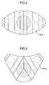
Figure 3 is a top view showing a construction
of the magnet for the MRI apparatus according to the
embodiment of the invention.
Figure 4 is a top view showing a construction
of the magnet for the MRI apparatus according to
another embodiment of the invention.
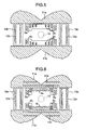
Figure 5 is a cross-sectional view showing a
construction of a magnet for the MRI apparatus
according to another embodiment of the invention.
Figure 6 is a cross-sectional view showing a
construction of a magnet for the MRI apparatus
according to still another embodiment of the invention.
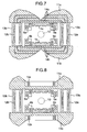
Figure 7 is a cross-sectional view showing a
construction of a magnet for the MRI apparatus
according to yet another embodiment of the invention.
Figure 8 is a cross-sectional view showing a
construction of a magnet for the MRI apparatus
according to a further embodiment of the invention.
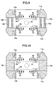
Figure 9 is a cross-sectional view showing a
construction of a magnet for the MRI apparatus
according to a further embodiment of the invention.
Figure 10 is a cross-sectional view showing a
construction of a magnet for the MRI apparatus
according to a further embodiment of the invention.
Figure 11 is a cross-sectional view showing a
construction of a magnet for the MRI apparatus
according to a further embodiment of the invention.
Figure 12 is a cross-sectional view showing a
construction of a magnet for the MRI apparatus
according to a further embodiment of the invention.
DESCRIPTION OF THE EMBODIMENTS
The MRI apparatus mainly includes a static
magnetic field generating unit to apply a homogeneous
static magnetic field in an imaging volume, an RF coil
system to transmit and receive an electromagnetic wave,
and a gradient magnetic field generating unit to apply
a gradient magnetic field that gives position
information on a resonant phenomenon.
The MRI apparatus can be divided largely into
two categories mainly in terms of a magnetic field
application method. One is a horizontal magnetic field
apparatus in which an imaging volume is placed in an
internal space of a group of coils arranged coaxially
in multiple layers, and the other is a vertical
magnetic field apparatus (open type) in which an
imaging volume is sandwiched between opposing coil
groups. Because of its openness the vertical magnetic
field apparatus reduces a psychological burden on a
patient and significantly improves an accessibility to
the patient by an inspector. Therefore, the vertical
magnetic field apparatus is becoming a mainstream of
the MRI apparatus.
Fig. 2 shows an example construction of an
open type MRI apparatus. Main constitutional elements
of the apparatus include magnetic poles 1a, 1b for
applying a homogeneous magnetic field to an imaging
area 10 that forms an imaging volume, superconducting
magnets 5a, 5b as a source of magnetomotive force,
cryostats 6a, 6b for keeping the superconducting
magnets at low temperatures, gradient magnetic field
coils 7a, 7b for applying a gradient magnetic field
that gives position information on a resonant
phenomenon, RF coil systems 8a, 8b for transmitting and
receiving electromagnetic waves, and homogeneity
adjusting units 9a, 9b for adjusting a field
homogeneity in the imaging volume. These pairs are
opposed to each other with the measurement space in
between.
Since the MRI apparatus are mainly installed
in hospitals for medical treatments, not only is the
imaging performance, the primary object of the
apparatus, important but an ease of installation of the
MRI apparatus also matters. A dominant factor that
determines the ease of installation is the size and
weight of the MRI apparatus and the spread of the
magnetic flux leaking from the MRI apparatus. As for
the size and weight of the apparatus, it is needless to
say that the smaller and the lighter, the better. As
for the leakage fluxes, a value of 5 gauss is used as a
criterion for the magnetic field strength that does not
affect pacemakers and other medical equipment and it is
required that the magnetic field strength at least
outside a room where the MRI apparatus is installed be
5 gauss or less.
In the MRI apparatus, since an increase in
the intensity of static magnetic field results in an
increased resonant signal strength leading to a reduced
imaging time and a higher function imaging, efforts are
being made to enhance the intensity of magnetic field.
Simply increasing a magnetomotive force of a magnetic
field source for a higher magnetic field strength
naturally increases leakage fluxes. The open type MRI
apparatus employs a method of confining or canceling
the magnetic flux leaking from a source of magnetic
field to reduce the leakage fluxes.
For reducing leakage fluxes mainly three
types of method are available: a passive shield type,
an active shield type and a toroidal coil type (e.g.,
Japanese Patent Laid-Open No. 10-4010). In the passive
shield type, two opposing magnetic field generating
sources are linked together with a ferromagnetic
material such as iron to form a magnetic flux path so
that a magnetic flux generated by one of the magnetic
field generating sources is confined within the flux
path and returned to the other magnetic field
generating source, thus reducing the leakage fluxes.
In the active shield type, shield coils that generate
opposing magnetic fields are arranged on the outer
sides of the opposing magnetic field generating sources
to cancel out external leakage fluxes thereby reducing
them. In the toroidal coil type, because a perfect
toroidal coil completely eliminates the leakage fluxes,
the coils are arranged in a C-shaped configuration like
the toroidal coils to reduce the leakage fluxes.
While the passive shield type can reduce the
spread of leakage fluxes and maximize the center
magnetic field strength and therefore can reduce the
magnetomotive force of the magnet, because the magnetic
circuit is constructed of a ferromagnetic material such
as iron, the weight of the magnet becomes very heavy.
In the active shield type, although the magnet weight
is reduced, since a shield magnetic field is generated
in a direction that cancels out the static magnetic
field necessary for imaging, the magnetomotive force of
the magnet tends to increase and the leakage fluxes
become comparatively large. In the toroidal coil type,
since a magnetic field is generated in a way that does
not cancel out (but rather increases) the static
magnetic field of the imaging volume, it is
advantageous from the standpoint of magnetomotive force
and the weight of the magnet is comparatively small.
In practice, however, arranging the coils in a perfect
toroidal coil configuration is difficult and magnetic
fluxes leak from gaps between coils arranged in a
toroidal shape. As a result, the leakage fluxes are
not reduced as expected and the structure of the magnet
itself tends to become complex and large.
Fig. 1 and Fig. 3 show a cross-sectional view
and a top view of the magnet for the MRI apparatus
according to one embodiment of this invention. In the
MRI apparatus magnet, static magnetic field generating
units are opposed to each other with an imaging volume
in between. The static magnetic field generating units
includes superconducting magnets 5a, 5b, 5c, 5d,
cryostats 6a, 6b containing the superconducting magnets
5a, 5b, 5c, 5d, and magnetic poles 1a, 1b of a magnetic
material arranged to concentrate or disperse magnetic
flux lines threading through the superconducting magnet
in the imaging area 10 as the imaging volume.
Installed beside the static magnetic field generating
units are magnetic flux return coils 12a, 12b that
generate magnetic fields of polarities that oppose
those of the magnetic fields generated by the static
magnetic field generating units in the imaging area 10
as the imaging volume, and cryostats 13a, 13b
accommodating the magnetic flux return coils 12a, 12b.
Yokes 11a, 11b are arranged to link end faces of the
static magnetic field generating units with end faces
of the magnetic flux return coils to form a magnetic
circuit.
A magnetic flux generated in a vertically
upward direction in the imaging area 10 or the imaging
volume by the static magnetic field generating units
passes through the upper static magnetic field
generating unit, is led out in a horizontal direction
by the upper yoke 11a, passes downward through the
magnetic flux return coils 12a, 12b, is converged
horizontally by the lower yoke 11b to the lower static
magnetic field generating unit, and passes upward
through the lower static magnetic field generating
unit, thus making a complete circuit. By designing a
cross section of the magnetic circuit of the
ferromagnetic material and also designing a magnetic
flux quantity generated by the magnetic flux return
coils 12a, 12b, i.e., their magnetomotive forces, and
cross sections of the magnetic flux return coils in
such a way as to pass the magnetic flux quantity
generated by the static magnetic field generating
units, it is possible to confine the flux generated by
the static magnetic field generating units in this
magnetic circuit, thus reducing the leakage fluxes.
In this embodiment, two magnetic flux return
coils 80 cm in inner diameter are arranged to realize a
magnet that has a static magnetic field strength of 1.5
tesla and a 5-gauss line of the leakage fluxes lying
within a sphere 2.9 m in radius. The use of the yokes
11a, 11b has made it possible to confine the leakage
fluxes to the proximity of the static magnetic field
generating units. By optimizing the geometries of the
yokes 11a, 11b, a total height of the magnet that meets
the specifications described above can be kept within
2.4 m. Since the magnetic circuit is constructed of
the yokes and the magnetic flux return coil currents,
the total weight of the yokes can be made small at
about 42 tons. Comparing it with an existing open type
MRI apparatus currently available in the market which
has a static magnetic field strength of 0.7 tesla and a
total weight of 40 tons, the apparatus of this
embodiment has kept its weight at nearly the same level
while its static magnetic field strength has doubled.
This practically means that this invention has realized
a weight reduction.
This embodiment is characterized in that the
portions of the magnetic circuit that return the fluxes
vertically, i.e., the column portions, are constructed
of coils, not ferromagnetic paths. Constructing these
columns by using a ferromagnetic material requires the
cross-sectional areas of these columns to be increased
proportionally with an increase in the static magnetic
field strength, thus reducing the level of openness at
an opening of the magnet. With these columns
constructed of the magnetic flux return coils, the coil
magnetomotive force needs only to be increased
according to an increase in the static magnetic field
strength, minimizing the influence on the openness of
the magnet.
In this embodiment, two magnetic flux return
coils 12a, 12b of 80 cm in inner diameter were used
which were made from NbTi, a superconducting material
most commonly used in a low magnetic field range. The
maximum magnetic field to which the magnetic flux
return coils are subjected is 4 tesla or less. In
enhancing the openness of the magnet, it is effective
to reduce the diameter of the magnetic flux return coil
columns. However, because a certain magnetic flux
quantity passing through the magnetic flux return coil
columns must be secured, the maximum magnetic field
experienced by the reduced-diameter magnetic flux
return coil columns increases. Roughly speaking, the
experienced magnetic field is inversely proportional to
the diameter of the magnetic flux return coils squared.
For example, if Nb3Sn having a stronger resistance
against the magnetic field is used to construct the
magnetic flux return coils, their diameters can be
reduced to 60 cm, further improving the openness of the
magnet.
Since the current that the superconducting
material can conduct is limited by the magnetic field
to which the superconducting material is subjected, it
is necessary to select a superconducting material that
can conduct current under a higher magnetic field in
order to reduce the diameter of the magnetic flux
return coils. Such materials include superconducting
metals such as Nb3Sn, Nb3Al and MgB2, or superconducting
oxides such as Bi-, Y-, Hg- and Tl-based materials.
The diameter of the column portions may also be reduced
by using a material with a high critical temperature
for the coils to simplify the structure of the
cryostats which hold the magnetic flux return coils.
Such materials include superconducting oxide materials
such as Bi-, Y-, Hg- and Tl-based materials and metal
materials with a relatively high critical temperature,
such as MgB2.
If the magnet is constructed of
superconducting coils and the operation of the magnet
requires a medium such as liquefied helium and
liquefied nitrogen, cooling equipment such as a cooling
medium tank, a heat exchanger and a refrigerator are
needed. These equipment may be installed in internal
spaces of the magnetic flux return coil currents to
eliminate the need for an additional space for their
accommodation, rendering the magnet compact.
While this embodiment has two magnetic flux
return coils to secure two magnetic flux return paths,
other configurations may be employed. According to a
design of leakage flux geometry and an openness at the
opening of the magnet, the apparatus may have only one
magnetic circuit or the so-called C type configuration,
or additional magnetic flux return coils may be used.
A primary cause for the leakage fluxes in the magnet
with the magnetic circuit of this embodiment is the
presence of gaps between the magnetic flux paths of
ferromagnetic materials and the return coils. To make
the spread of the 5-gauss line of leakage fluxes small,
it is effective to distributively arrange a plurality
of flux return paths. The magnetic flux return coils
12a, 12b and the static magnetic field generating
units, when viewed from above, are arranged in line.
By shifting the positions of the magnetic flux return
coils, a magnet opening on the side that is frequently
accessed can be made wide and more easily accessible,
as shown in Fig. 4.
Further, arranging with a good balance the
ferromagnetic material flux return paths that form a
plurality of magnetic flux return paths makes it
possible to control the spread of leakage fluxes caused
by residual magnetizations in the ferromagnetic
materials and an attenuation time constant, the
residual magnetizations occurring when the magnetic
flux return paths are interrupted by the magnetic flux
return coils changing to a resistive state due to
thermal instability.
In the MRI magnet the homogeneity of the
static magnetic field is important. In this
embodiment, the field homogeneity is secured by two
pairs of coils and magnetic poles formed with grooves,
as shown in the figure. Means for securing the field
homogeneity is not limited to the configuration of this
embodiment. For example, a plurality of coils may be
used instead of the magnetic poles formed with grooves,
as shown in Fig. 5, to generate a homogeneous field.
Since a homogeneous field can be produced in
the imaging volume by the static magnetic field
generating units including the magnetic poles, there is
no need to adjust the flow of flux in the magnetic flux
path or to make the flow of flux introduced into the
static magnetic field generating units homogeneously.
However, for simplifying the construction of the
magnetic poles, the flow of flux may be controlled by
adjusting the geometry of the magnetic flux paths and
using gaps and materials having magnetic anisotropy.
Further, it is also possible to place in the magnetic
flux paths ferromagnetic materials and permanent
magnets that generate auxiliary magnetic fields.
For reducing the size of the 5-gauss line of
leakage fluxes, it is important to confine the flux to
the proximity of the magnet as it is returned to the
field sources. Therefore, in this embodiment the yokes
11a, 11b of a ferromagnetic material are arranged above
and below the static magnetic field generating units.
To utilize these yokes more effectively for confining
the flux, horizontal slits are formed in the yokes as
shown in Fig. 6. While in the figure the upper and
lower yokes are each shown to be formed with two slits
14a, 14b, they each actually have four 5-mm-thick
slits. The slits extend from the center of the static
magnetic field generating units to where the magnetic
flux lines parallelly bend.
Since the flux tends to bend toward where the
permeability is large, the flux going out upwardly from
the static magnetic field generating unit bends so that
it flows parallel to the air layer. Hence, the flux
that would otherwise escape upwardly can be efficiently
confined horizontally. With the flux confined
compactly in this manner, the volume of the magnetic
flux path of a ferromagnetic material required to pass
the flux can be reduced, which in turn leads to a
reduced weight. The use of the slits has reduced the
weight of the yokes 11a, 11b down to about 39 tons.
As described above, controlling the flux by
taking advantage of a difference in permeability is
very effective. The similar effects can also be
produced by using laminated sheets of metal having a
permeability anisotropy. While in this embodiment the
slits are arranged in a part of the yokes, it is also
effective to form such slits over the entire length of
the yokes, as shown in Fig. 7, so as to form a desired
flow of magnetic flux. The yokes having these slits
may be formed by assembling constitutional parts.
In this embodiment, to realize a compact
magnet with a reduced total height, the magnetic flux
paths of ferromagnetic materials, that are designed to
lead the leakage fluxes escaping vertically from the
static magnetic field generating units to a horizontal
direction, are arranged above and below the static
magnetic field generating units. Another method for
realizing a compact magnet involves, as shown in Fig.
8, installing above and below the static magnetic field
sources magnetic flux control coils 15a, 15b that
generate magnetic fields whose polarities are opposite
to those of the static magnetic field generating units.
A flux generated by the static magnetic field sources
and a flux generated by the flux control coils collide
with each other forming a flow of flux welling out
horizontally. The shape of the magnetic flux control
coils is not limited to a circle and their attitude not
limited to a perfectly horizontal one. In the toroidal
coil type, the returning fluxes all thread through the
coils, whereas in this type the returning fluxes do not
thread through the magnetic flux control coils. The
presence of the yokes alleviates the degree to which
the reverse magnetic fields generated by the magnetic
flux control coils reduce the static magnetic field
intensity in the imaging volume. The magnetic poles
still have an effect of strengthening the intensity of
the static magnetic field. The presence of yokes
between the magnetic flux control coils and the static
magnetic field generating units increases the number of
cryostats and complicates the structure. To solve this
problem, a method may be adopted which involves
eliminating the yokes and the magnetic poles and
storing the magnetic flux control coils and the coils
of the static magnetic field generating units in the
same cryostat, as shown in Fig. 9. In this method, the
magnetic flux control coils tend to increase in size
and thus the reverse magnetic field generated by the
magnetic flux control coils have a greater influence on
the imaging volume, resulting in an increase in the
magnetomotive force of the static magnetic field
generating units. This method, however, can greatly
reduce the weight of the magnet.
A magnet shown in Fig. 10 has yoke columns
16a, 16b that have replaced the magnetic flux return
coils of Fig. 9. In the MRI apparatus, vibrations of
the magnet vary the magnetic field in the imaging
volume and greatly influence the quality of an image
formed. By replacing the magnetic flux return coils
with the yoke columns 16a, 16b to increase the rigidity
of the magnet, the resonance frequency can be shifted
to a higher frequency side, allowing the amplitude to
be reduced. Although this arrangement increases the
weight of the magnet, the influence of vibrations can
be reduced while maintaining the magnitude of the
leakage fluxes at about the same level as in other
types of magnet.
A magnet shown in Fig. 11 has the magnetic
flux return coils of Fig. 1 divided into top and bottom
coils, with a gap formed at each center between the
divided coils. Thus, four magnetic flux return coils
are shown. A structure for supporting iron members and
cryostats are not shown. A more preferred embodiment
is shown in Fig. 12, in which coils making up the
magnet are divided into top and bottom groups and the
coils of each group are installed in one integral
cryostat which is formed flat at its bottom surface.
This arrangement can significantly simplify the
structure of the cryostats. The upper and lower
cryostats are connected by joint pipes 17a, 17b,
through which electric circuits, cooling systems and
coil supporting structures for the upper and lower
coils are connected (not shown). The joint pipes can
be made much smaller in diameter than the magnetic flux
return coils that are arranged as single continuous
columns between yokes, thereby greatly improving the
openness of the magnet.
In the MRI magnet described above, since the
magnetic circuit is comprised of flux paths generated
by the ferromagnetic materials and flux paths generated
by the magnetic flux return coils or the magnetic flux
control coils, even when the static magnetic field
intensity exceeds 1 tesla, the 5-gauss line of the
leakage fluxes can be confined within a sphere 3.5 m in
radius while minimizing the weight increase of the
magnet. Further, by adopting the construction that
compactly leads to the horizontal direction the flux
which would otherwise escape vertically from the static
magnetic field sources, the overall height increase of
the magnet can be minimized and the magnet with a total
height within 3 m can be realized.
The magnet for magnetic resonance imaging
apparatus described in the foregoing includes, for
example, a plurality of static magnetic field
generating units arranged to generally oppose each
other, an imaging volume formed by the opposing static
magnetic field generating units, and a magnetic circuit
to return magnetic fluxes generated by the static
magnetic field generating units, wherein the magnetic
circuit includes a magnetic flux path formed by a
ferromagnetic material such as iron and a magnetic flux
path formed by an arrangement of current, such as coil-shaped
current. In this specification, the arrangement
of current is accomplished, for example, by the
superconducting materials described above and its
geometry may include a coil-shaped current, a sheet-shaped
current and a bulk superconductor, or a
combination of these.
It should be further understood by those
skilled in the art that although the foregoing
description has been made on embodiments of the
invention, the invention is not limited thereto and
various changes and modifications may be made without
departing from the spirit of the invention and the
scope of the appended claims.