EP1319887A2 - Vapor delivery from a low vapor pressure liquefied compressed gas - Google Patents
Vapor delivery from a low vapor pressure liquefied compressed gas Download PDFInfo
- Publication number
- EP1319887A2 EP1319887A2 EP02027518A EP02027518A EP1319887A2 EP 1319887 A2 EP1319887 A2 EP 1319887A2 EP 02027518 A EP02027518 A EP 02027518A EP 02027518 A EP02027518 A EP 02027518A EP 1319887 A2 EP1319887 A2 EP 1319887A2
- Authority
- EP
- European Patent Office
- Prior art keywords
- component
- vapor
- reservoir
- liquid
- outlet
- Prior art date
- Legal status (The legal status is an assumption and is not a legal conclusion. Google has not performed a legal analysis and makes no representation as to the accuracy of the status listed.)
- Withdrawn
Links
Images
Classifications
-
- C—CHEMISTRY; METALLURGY
- C23—COATING METALLIC MATERIAL; COATING MATERIAL WITH METALLIC MATERIAL; CHEMICAL SURFACE TREATMENT; DIFFUSION TREATMENT OF METALLIC MATERIAL; COATING BY VACUUM EVAPORATION, BY SPUTTERING, BY ION IMPLANTATION OR BY CHEMICAL VAPOUR DEPOSITION, IN GENERAL; INHIBITING CORROSION OF METALLIC MATERIAL OR INCRUSTATION IN GENERAL
- C23C—COATING METALLIC MATERIAL; COATING MATERIAL WITH METALLIC MATERIAL; SURFACE TREATMENT OF METALLIC MATERIAL BY DIFFUSION INTO THE SURFACE, BY CHEMICAL CONVERSION OR SUBSTITUTION; COATING BY VACUUM EVAPORATION, BY SPUTTERING, BY ION IMPLANTATION OR BY CHEMICAL VAPOUR DEPOSITION, IN GENERAL
- C23C16/00—Chemical coating by decomposition of gaseous compounds, without leaving reaction products of surface material in the coating, i.e. chemical vapour deposition [CVD] processes
- C23C16/44—Chemical coating by decomposition of gaseous compounds, without leaving reaction products of surface material in the coating, i.e. chemical vapour deposition [CVD] processes characterised by the method of coating
- C23C16/455—Chemical coating by decomposition of gaseous compounds, without leaving reaction products of surface material in the coating, i.e. chemical vapour deposition [CVD] processes characterised by the method of coating characterised by the method used for introducing gases into reaction chamber or for modifying gas flows in reaction chamber
- C23C16/45561—Gas plumbing upstream of the reaction chamber
-
- C—CHEMISTRY; METALLURGY
- C23—COATING METALLIC MATERIAL; COATING MATERIAL WITH METALLIC MATERIAL; CHEMICAL SURFACE TREATMENT; DIFFUSION TREATMENT OF METALLIC MATERIAL; COATING BY VACUUM EVAPORATION, BY SPUTTERING, BY ION IMPLANTATION OR BY CHEMICAL VAPOUR DEPOSITION, IN GENERAL; INHIBITING CORROSION OF METALLIC MATERIAL OR INCRUSTATION IN GENERAL
- C23C—COATING METALLIC MATERIAL; COATING MATERIAL WITH METALLIC MATERIAL; SURFACE TREATMENT OF METALLIC MATERIAL BY DIFFUSION INTO THE SURFACE, BY CHEMICAL CONVERSION OR SUBSTITUTION; COATING BY VACUUM EVAPORATION, BY SPUTTERING, BY ION IMPLANTATION OR BY CHEMICAL VAPOUR DEPOSITION, IN GENERAL
- C23C16/00—Chemical coating by decomposition of gaseous compounds, without leaving reaction products of surface material in the coating, i.e. chemical vapour deposition [CVD] processes
- C23C16/44—Chemical coating by decomposition of gaseous compounds, without leaving reaction products of surface material in the coating, i.e. chemical vapour deposition [CVD] processes characterised by the method of coating
- C23C16/448—Chemical coating by decomposition of gaseous compounds, without leaving reaction products of surface material in the coating, i.e. chemical vapour deposition [CVD] processes characterised by the method of coating characterised by the method used for generating reactive gas streams, e.g. by evaporation or sublimation of precursor materials
- C23C16/4485—Chemical coating by decomposition of gaseous compounds, without leaving reaction products of surface material in the coating, i.e. chemical vapour deposition [CVD] processes characterised by the method of coating characterised by the method used for generating reactive gas streams, e.g. by evaporation or sublimation of precursor materials by evaporation without using carrier gas in contact with the source material
-
- F—MECHANICAL ENGINEERING; LIGHTING; HEATING; WEAPONS; BLASTING
- F17—STORING OR DISTRIBUTING GASES OR LIQUIDS
- F17C—VESSELS FOR CONTAINING OR STORING COMPRESSED, LIQUEFIED OR SOLIDIFIED GASES; FIXED-CAPACITY GAS-HOLDERS; FILLING VESSELS WITH, OR DISCHARGING FROM VESSELS, COMPRESSED, LIQUEFIED, OR SOLIDIFIED GASES
- F17C7/00—Methods or apparatus for discharging liquefied, solidified, or compressed gases from pressure vessels, not covered by another subclass
- F17C7/02—Discharging liquefied gases
- F17C7/04—Discharging liquefied gases with change of state, e.g. vaporisation
-
- F—MECHANICAL ENGINEERING; LIGHTING; HEATING; WEAPONS; BLASTING
- F17—STORING OR DISTRIBUTING GASES OR LIQUIDS
- F17C—VESSELS FOR CONTAINING OR STORING COMPRESSED, LIQUEFIED OR SOLIDIFIED GASES; FIXED-CAPACITY GAS-HOLDERS; FILLING VESSELS WITH, OR DISCHARGING FROM VESSELS, COMPRESSED, LIQUEFIED, OR SOLIDIFIED GASES
- F17C2203/00—Vessel construction, in particular walls or details thereof
- F17C2203/06—Materials for walls or layers thereof; Properties or structures of walls or their materials
- F17C2203/0634—Materials for walls or layers thereof
- F17C2203/0636—Metals
- F17C2203/0648—Alloys or compositions of metals
-
- F—MECHANICAL ENGINEERING; LIGHTING; HEATING; WEAPONS; BLASTING
- F17—STORING OR DISTRIBUTING GASES OR LIQUIDS
- F17C—VESSELS FOR CONTAINING OR STORING COMPRESSED, LIQUEFIED OR SOLIDIFIED GASES; FIXED-CAPACITY GAS-HOLDERS; FILLING VESSELS WITH, OR DISCHARGING FROM VESSELS, COMPRESSED, LIQUEFIED, OR SOLIDIFIED GASES
- F17C2205/00—Vessel construction, in particular mounting arrangements, attachments or identifications means
- F17C2205/03—Fluid connections, filters, valves, closure means or other attachments
- F17C2205/0302—Fittings, valves, filters, or components in connection with the gas storage device
- F17C2205/0338—Pressure regulators
-
- F—MECHANICAL ENGINEERING; LIGHTING; HEATING; WEAPONS; BLASTING
- F17—STORING OR DISTRIBUTING GASES OR LIQUIDS
- F17C—VESSELS FOR CONTAINING OR STORING COMPRESSED, LIQUEFIED OR SOLIDIFIED GASES; FIXED-CAPACITY GAS-HOLDERS; FILLING VESSELS WITH, OR DISCHARGING FROM VESSELS, COMPRESSED, LIQUEFIED, OR SOLIDIFIED GASES
- F17C2221/00—Handled fluid, in particular type of fluid
- F17C2221/01—Pure fluids
- F17C2221/011—Oxygen
-
- F—MECHANICAL ENGINEERING; LIGHTING; HEATING; WEAPONS; BLASTING
- F17—STORING OR DISTRIBUTING GASES OR LIQUIDS
- F17C—VESSELS FOR CONTAINING OR STORING COMPRESSED, LIQUEFIED OR SOLIDIFIED GASES; FIXED-CAPACITY GAS-HOLDERS; FILLING VESSELS WITH, OR DISCHARGING FROM VESSELS, COMPRESSED, LIQUEFIED, OR SOLIDIFIED GASES
- F17C2221/00—Handled fluid, in particular type of fluid
- F17C2221/01—Pure fluids
- F17C2221/012—Hydrogen
-
- F—MECHANICAL ENGINEERING; LIGHTING; HEATING; WEAPONS; BLASTING
- F17—STORING OR DISTRIBUTING GASES OR LIQUIDS
- F17C—VESSELS FOR CONTAINING OR STORING COMPRESSED, LIQUEFIED OR SOLIDIFIED GASES; FIXED-CAPACITY GAS-HOLDERS; FILLING VESSELS WITH, OR DISCHARGING FROM VESSELS, COMPRESSED, LIQUEFIED, OR SOLIDIFIED GASES
- F17C2221/00—Handled fluid, in particular type of fluid
- F17C2221/01—Pure fluids
- F17C2221/014—Nitrogen
-
- F—MECHANICAL ENGINEERING; LIGHTING; HEATING; WEAPONS; BLASTING
- F17—STORING OR DISTRIBUTING GASES OR LIQUIDS
- F17C—VESSELS FOR CONTAINING OR STORING COMPRESSED, LIQUEFIED OR SOLIDIFIED GASES; FIXED-CAPACITY GAS-HOLDERS; FILLING VESSELS WITH, OR DISCHARGING FROM VESSELS, COMPRESSED, LIQUEFIED, OR SOLIDIFIED GASES
- F17C2221/00—Handled fluid, in particular type of fluid
- F17C2221/01—Pure fluids
- F17C2221/016—Noble gases (Ar, Kr, Xe)
- F17C2221/017—Helium
-
- F—MECHANICAL ENGINEERING; LIGHTING; HEATING; WEAPONS; BLASTING
- F17—STORING OR DISTRIBUTING GASES OR LIQUIDS
- F17C—VESSELS FOR CONTAINING OR STORING COMPRESSED, LIQUEFIED OR SOLIDIFIED GASES; FIXED-CAPACITY GAS-HOLDERS; FILLING VESSELS WITH, OR DISCHARGING FROM VESSELS, COMPRESSED, LIQUEFIED, OR SOLIDIFIED GASES
- F17C2221/00—Handled fluid, in particular type of fluid
- F17C2221/03—Mixtures
- F17C2221/032—Hydrocarbons
- F17C2221/033—Methane, e.g. natural gas, CNG, LNG, GNL, GNC, PLNG
-
- F—MECHANICAL ENGINEERING; LIGHTING; HEATING; WEAPONS; BLASTING
- F17—STORING OR DISTRIBUTING GASES OR LIQUIDS
- F17C—VESSELS FOR CONTAINING OR STORING COMPRESSED, LIQUEFIED OR SOLIDIFIED GASES; FIXED-CAPACITY GAS-HOLDERS; FILLING VESSELS WITH, OR DISCHARGING FROM VESSELS, COMPRESSED, LIQUEFIED, OR SOLIDIFIED GASES
- F17C2221/00—Handled fluid, in particular type of fluid
- F17C2221/03—Mixtures
- F17C2221/032—Hydrocarbons
- F17C2221/035—Propane butane, e.g. LPG, GPL
-
- F—MECHANICAL ENGINEERING; LIGHTING; HEATING; WEAPONS; BLASTING
- F17—STORING OR DISTRIBUTING GASES OR LIQUIDS
- F17C—VESSELS FOR CONTAINING OR STORING COMPRESSED, LIQUEFIED OR SOLIDIFIED GASES; FIXED-CAPACITY GAS-HOLDERS; FILLING VESSELS WITH, OR DISCHARGING FROM VESSELS, COMPRESSED, LIQUEFIED, OR SOLIDIFIED GASES
- F17C2223/00—Handled fluid before transfer, i.e. state of fluid when stored in the vessel or before transfer from the vessel
- F17C2223/01—Handled fluid before transfer, i.e. state of fluid when stored in the vessel or before transfer from the vessel characterised by the phase
- F17C2223/0146—Two-phase
- F17C2223/0153—Liquefied gas, e.g. LPG, GPL
-
- F—MECHANICAL ENGINEERING; LIGHTING; HEATING; WEAPONS; BLASTING
- F17—STORING OR DISTRIBUTING GASES OR LIQUIDS
- F17C—VESSELS FOR CONTAINING OR STORING COMPRESSED, LIQUEFIED OR SOLIDIFIED GASES; FIXED-CAPACITY GAS-HOLDERS; FILLING VESSELS WITH, OR DISCHARGING FROM VESSELS, COMPRESSED, LIQUEFIED, OR SOLIDIFIED GASES
- F17C2225/00—Handled fluid after transfer, i.e. state of fluid after transfer from the vessel
- F17C2225/01—Handled fluid after transfer, i.e. state of fluid after transfer from the vessel characterised by the phase
- F17C2225/0107—Single phase
- F17C2225/0123—Single phase gaseous, e.g. CNG, GNC
-
- F—MECHANICAL ENGINEERING; LIGHTING; HEATING; WEAPONS; BLASTING
- F17—STORING OR DISTRIBUTING GASES OR LIQUIDS
- F17C—VESSELS FOR CONTAINING OR STORING COMPRESSED, LIQUEFIED OR SOLIDIFIED GASES; FIXED-CAPACITY GAS-HOLDERS; FILLING VESSELS WITH, OR DISCHARGING FROM VESSELS, COMPRESSED, LIQUEFIED, OR SOLIDIFIED GASES
- F17C2227/00—Transfer of fluids, i.e. method or means for transferring the fluid; Heat exchange with the fluid
- F17C2227/03—Heat exchange with the fluid
- F17C2227/0302—Heat exchange with the fluid by heating
-
- F—MECHANICAL ENGINEERING; LIGHTING; HEATING; WEAPONS; BLASTING
- F17—STORING OR DISTRIBUTING GASES OR LIQUIDS
- F17C—VESSELS FOR CONTAINING OR STORING COMPRESSED, LIQUEFIED OR SOLIDIFIED GASES; FIXED-CAPACITY GAS-HOLDERS; FILLING VESSELS WITH, OR DISCHARGING FROM VESSELS, COMPRESSED, LIQUEFIED, OR SOLIDIFIED GASES
- F17C2227/00—Transfer of fluids, i.e. method or means for transferring the fluid; Heat exchange with the fluid
- F17C2227/03—Heat exchange with the fluid
- F17C2227/0337—Heat exchange with the fluid by cooling
-
- F—MECHANICAL ENGINEERING; LIGHTING; HEATING; WEAPONS; BLASTING
- F17—STORING OR DISTRIBUTING GASES OR LIQUIDS
- F17C—VESSELS FOR CONTAINING OR STORING COMPRESSED, LIQUEFIED OR SOLIDIFIED GASES; FIXED-CAPACITY GAS-HOLDERS; FILLING VESSELS WITH, OR DISCHARGING FROM VESSELS, COMPRESSED, LIQUEFIED, OR SOLIDIFIED GASES
- F17C2227/00—Transfer of fluids, i.e. method or means for transferring the fluid; Heat exchange with the fluid
- F17C2227/03—Heat exchange with the fluid
- F17C2227/0367—Localisation of heat exchange
- F17C2227/0369—Localisation of heat exchange in or on a vessel
- F17C2227/0376—Localisation of heat exchange in or on a vessel in wall contact
- F17C2227/0383—Localisation of heat exchange in or on a vessel in wall contact outside the vessel
-
- F—MECHANICAL ENGINEERING; LIGHTING; HEATING; WEAPONS; BLASTING
- F17—STORING OR DISTRIBUTING GASES OR LIQUIDS
- F17C—VESSELS FOR CONTAINING OR STORING COMPRESSED, LIQUEFIED OR SOLIDIFIED GASES; FIXED-CAPACITY GAS-HOLDERS; FILLING VESSELS WITH, OR DISCHARGING FROM VESSELS, COMPRESSED, LIQUEFIED, OR SOLIDIFIED GASES
- F17C2250/00—Accessories; Control means; Indicating, measuring or monitoring of parameters
- F17C2250/06—Controlling or regulating of parameters as output values
- F17C2250/0605—Parameters
- F17C2250/0636—Flow or movement of content
-
- F—MECHANICAL ENGINEERING; LIGHTING; HEATING; WEAPONS; BLASTING
- F17—STORING OR DISTRIBUTING GASES OR LIQUIDS
- F17C—VESSELS FOR CONTAINING OR STORING COMPRESSED, LIQUEFIED OR SOLIDIFIED GASES; FIXED-CAPACITY GAS-HOLDERS; FILLING VESSELS WITH, OR DISCHARGING FROM VESSELS, COMPRESSED, LIQUEFIED, OR SOLIDIFIED GASES
- F17C2265/00—Effects achieved by gas storage or gas handling
- F17C2265/01—Purifying the fluid
- F17C2265/012—Purifying the fluid by filtering
-
- F—MECHANICAL ENGINEERING; LIGHTING; HEATING; WEAPONS; BLASTING
- F17—STORING OR DISTRIBUTING GASES OR LIQUIDS
- F17C—VESSELS FOR CONTAINING OR STORING COMPRESSED, LIQUEFIED OR SOLIDIFIED GASES; FIXED-CAPACITY GAS-HOLDERS; FILLING VESSELS WITH, OR DISCHARGING FROM VESSELS, COMPRESSED, LIQUEFIED, OR SOLIDIFIED GASES
- F17C2270/00—Applications
- F17C2270/05—Applications for industrial use
- F17C2270/0518—Semiconductors
-
- Y—GENERAL TAGGING OF NEW TECHNOLOGICAL DEVELOPMENTS; GENERAL TAGGING OF CROSS-SECTIONAL TECHNOLOGIES SPANNING OVER SEVERAL SECTIONS OF THE IPC; TECHNICAL SUBJECTS COVERED BY FORMER USPC CROSS-REFERENCE ART COLLECTIONS [XRACs] AND DIGESTS
- Y02—TECHNOLOGIES OR APPLICATIONS FOR MITIGATION OR ADAPTATION AGAINST CLIMATE CHANGE
- Y02E—REDUCTION OF GREENHOUSE GAS [GHG] EMISSIONS, RELATED TO ENERGY GENERATION, TRANSMISSION OR DISTRIBUTION
- Y02E60/00—Enabling technologies; Technologies with a potential or indirect contribution to GHG emissions mitigation
- Y02E60/30—Hydrogen technology
- Y02E60/32—Hydrogen storage
Definitions
- Industrial gases which are utilized in small to moderate volumes are stored at ambient temperature in pressurized cylinders from which gas is withdrawn as needed.
- a pressure regulator generally is used to deliver the gas to the consumer at a constant pressure.
- Gases which have critical temperatures below ambient temperature are stored as supercritical fluids at maximum pressures determined by the design pressure ratings of the cylinders. Examples of these include low-boiling gases such as nitrogen, oxygen, hydrogen, helium, and methane, which are withdrawn from the storage cylinders without phase change.
- Gases which have critical temperatures above ambient temperature are stored in cylinders as saturated liquids at their respective vapor pressures, and these liquids vaporize as saturated vapor is withdrawn from the cylinders.
- Common examples of liquefied compressed gases are chlorine, ammonia, and light hydrocarbons such as propane and butane.
- Some liquefied compressed gases have vapor pressures at ambient temperature which are not far above atmospheric pressure.
- condensation can occur under certain operating conditions during gas transfer from a storage cylinder to the process tool. This is undesirable because condensation can interfere with the operation of downstream instruments such as flow controllers, can cause pressure fluctuations in the gas delivery system, and in certain cases can result in impurities in the transferred gas caused by leaching of metal components from the delivery system piping.
- heat tracing can be a high-maintenance item which is subject to failure at unpredictable times. Such failure can adversely impact the operation of the process tool and affect the efficiency of the overall manufacturing process. Regular monitoring of heat tracing systems can be cost-prohibitive and as a result usually is not practiced. In addition, the need for heat tracing generally minimizes the distance between the gas storage cylinder and the consumer.
- the invention relates to a method for delivering a vapor component product to an end user from a storage system which contains the component in coexisting liquid and vapor phases.
- the method comprises:
- the coexisting liquid and vapor phases of the component in the storage system may be contained in a storage vessel, and a vapor stream may be withdrawn from the storage vessel while liquid is vaporized therein.
- the component stream withdrawn from the storage system in (a) may be provided by regulating the pressure of the vapor stream from the storage vessel to provide the component stream at the first total pressure. If desired, the storage vessel may be heated.
- the dynamic pressure differential defined by the difference between the first total pressure and the second total pressure may be at least about 1.25 psi.
- the difference between the first temperature and the second temperature may be at least about 15°F.
- the component stream in the transfer line may be essentially all vapor.
- the component may be an essentially pure compound selected from the group consisting of tungsten hexafluoride, disilane, dichlorosilane, trichlorosilane, trimethylsilane, perfluorobutadiene, and chlorine.
- the total pressure at any point in the transfer line may be less than the vapor pressure of the compound at a temperature equal to the temperature at that point in the transfer line.
- the second total pressure at the outlet of the reservoir may be greater than the total pressure of the component stream at the inlet of the reservoir.
- the invention also relates to a method for controlling the delivery of a vapor component product to an end user from a storage system which contains the component in coexisting liquid and vapor phases, wherein the method comprises:
- the invention also includes a system for delivering a vapor component product to an end user from a storage system which contains the component in coexisting liquid and vapor phases, wherein the system comprises:
- the system may further comprise pressure regulating means installed between the storage vessel and the transfer line.
- the storage vessel may be made of a metal containing at least 99.9 weight % nickel.
- the reservoir may be a vertically-oriented cylindrical vessel having an upper end and a lower end, wherein the outlet is at the lower end, and wherein the vessel has a height to diameter ratio of at least about five.
- This cylindrical vessel may be made of a metal containing at least 99.9 weight % nickel.
- the condensed component in the reservoir typically forms a liquid column with a height of at least about 12 inches above the outlet of the reservoir.
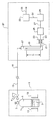
- the single Figure is a schematic flow diagram of an exemplary embodiment of the present invention.
- the present invention relates to an improved method for the transfer of low-boiling gases from pressurized liquid storage cylinders to end users while minimizing or eliminating condensation in the transfer lines.
- the method can be applied, for example, in the transfer of specialty gases from liquid storage cylinders in gas cabinets to process tools used in the semiconductor manufacturing industry.
- the method utilizes a thermosiphon system which maintains a temperature differential to assist in the transfer of gas between the storage cylinder and a cold reservoir. Condensation occurs in the cold reservoir which provides a static head of liquid, and the liquid is withdrawn therefrom and vaporized.
- the gas may be delivered to the flow controller as a superheated vapor at a pressure higher than the gas pressure in the transfer line from the gas storage cylinder.
- Cylinder 1 contains liquid 3 which typically is in thermal equilibrium or near thermal equilibrium with vapor 5.
- the total pressure within cylinder 1 is essentially the vapor pressure of liquid 3 at the temperature of cylinder 1.
- Cylinder 1 may be constructed of nickel or a high nickel alloy to minimize reaction with certain contained liquids.
- Liquid 3 typically is an essentially pure component which may contain certain impurities at low concentration. The impurities and concentration of the impurities may depend upon the particular component in liquid 3.
- the term "essentially pure” as used herein means that the concentration of total impurities is less than about 0.5 mole%.
- Cylinder 1 is typically fitted with shutoff valve 7 and pressure regulator 9, and may be installed in gas cabinet 11 which maintains a safe and controlled location for the cylinder.
- Gas cabinet 11 may contain multiple cylinders which are connected to gas manifolds.
- Heater 13 may be used to heat cylinder to 1 promote vaporization of liquid 3, for example, under high gas withdrawal rates.
- Transfer line 15, which may be double-walled tubing, may be made of type 316 stainless steel.
- Reservoir 17 is vertically-oriented and typically is a length of tubing or a small vessel which may have a height to diameter ratio in the range of about 5 to about 500. Reservoir 17 is cooled sufficiently by cooling system 19 to condense the gaseous component provided via transfer line 15 such that an inventory of condensed liquid having height h collects in the reservoir. Height h may be between about 1.0 inches and about 60 inches.
- the pressure exerted by the static head of condensed liquid in reservoir 17 preferably is equal to or greater than the dynamic pressure drop of the flowing fluid between the outlet of reservoir 17 and the inlet to reactor system 33. This liquid head provides a buffer to the variable dynamic pressure drop or dynamic pressure differential which occurs during normal system operation.
- the dynamic pressure drop or dynamic pressure differential is defined as the pressure drop or pressure differential of the flowing fluid between any two points in the system.
- Reservoir 17 may be constructed of nickel or a high nickel alloy to minimize reaction with certain contained liquids.
- the selection of the desired temperature of reservoir 17 will depend chiefly upon the component vapor pressure characteristics, the total pressure just downstream of pressure regulator 9, the flow rate of the component, and the ambient temperature of transfer line 15. The lower limit of the reservoir temperature is the freezing point of the component.
- pressure and “total pressure” as used herein are interchangeable and have the usual meaning wherein the pressure in an enclosed volume is the force exerted per unit area by the gas on the walls of the volume.
- vapor pressure has the usual thermodynamic meaning. For a pure component in an enclosed system at a given pressure, the component vapor pressure is essentially equal to the total pressure in the system.
- Cooling system 19 may utilize a recirculating refrigerant provided by a mechanical refrigeration system, cooling water, a vaporizing cryogenic liquid such as liquid nitrogen, or any other known cooling means to achieve the desired temperature.
- the amount of refrigeration provided by cooling system 19 typically is determined by the flow rate and latent heat of the gas being condensed, and may also depend upon the heat transfer characteristics of reservoir 17 as well as the insulation design of the system.
- Liquid is withdrawn from reservoir 17 via line 21 at a total pressure approximately equal to the liquid head h plus the total pressure of the gas at the inlet of reservoir 17. Withdrawn liquid is vaporized and optionally superheated in heater 23, and the vaporized component may pass through filter 25 to remove any particulate material or liquid mist which may be present.
- the gaseous component passes via line 27 into mass flow controller 29 and via line 31 to reactor system or deposition chamber 33, wherein the component is utilized in selected reactions to produce fabricated electronic components such as semiconductors. Vent gas is withdrawn via line 35 for recovery or disposal.
- Components 17, 19, 23, 25, 29, and 31, and the connecting piping, may be considered as parts of generic process tool 37. This process tool may be located a considerable distance from gas cabinet 11.
- the volume and height h of the liquid in reservoir 17 serves two purposes in the present invention.
- the reservoir capacity provides an inventory of the component which ensures proper delivery at varying demand from mass flow controller 29.
- the liquid head h provides a boost to the inlet pressure of mass flow controller 29, which improves overall process operation.
- the liquid component is tungsten hexalfuoride, a static pressure of 0.125 psia per inch of liquid head can be realized at the bottom of reservoir 17.
- the dynamic pressure differential between the outlet of pressure regulator 9 and the inlet of reservoir 17 may be at least about 1.0 psi.
- the dynamic pressure differential between the outlet of pressure regulator 9 and the outlet of reservoir 17 with a liquid column height of 18 inches, for example with liquid tungsten hexafluoride, may be at least about 1.25 psi.
- the difference between the temperature at the outlet of pressure regulator 9 and the outlet of reservoir 17 may be at least about 15°F.
- the method of the present invention can be used to increase the mass flow capacity of the system by increasing the cooling rate of cooling system 19 and by utilizing heater 13 on cylinder 1 as required.
- Gas flow is effected by the pressure differential between the outlet of pressure regulator 9 and the inlet of reservoir 17, and this differential pressure may be controlled to maximize component flow while minimizing or eliminating condensation in transfer line 15.
- the temperature of reservoir 17 is controlled by means of the temperature setting of cooling system 19, and the pressure at the inlet to reservoir 17 is determined by the vapor pressure of the component at that temperature.
- Pressure regulator 9 typically is a spring-loaded or gas-loaded diaphragm-type regulator, and the pressure just downstream of the regulator can be set by adjusting the diaphragm loading.
- the selection of the delivery pressure of regulator 9 and the temperature of reservoir 17 are two convenient parameters which control the pressure differential in transfer line 15, and the proper selection of these parameters can minimize or eliminate condensation in transfer line 15.
- the gas demand of reactor system or deposition chamber 33 typically varies in a cyclic manner, since the processing therein is carried out in a batch mode. This varying gas demand stresses a conventional gas delivery system and may promote condensation because of unsteady-state flows and pressure drops in the system.
- the method of the present invention can accommodate cyclic gas demands and minimize or eliminate condensation in the transfer line by virtue of the liquid inventory in reservoir 17.
- Cylinder 1 contains tungsten hexafluoride (WF 6 ) at 70°F and a cylinder pressure of 17.1 psia (884 torr). Vaporized WF 6 is withdrawn through shutoff valve 6 and flows through pressure regulator 9, which is set to control the regulator outlet pressure at 10 psia (517 torr). Vapor flows through transfer line 15 at the ambient temperature of 70°F and is condensed in reservoir 17. Reservoir 17 is cooled and maintained at 40°F, at which temperature the saturated vapor pressure of WF 6 is 8.7 psia (450 torr). The static pressure differential between the outlet of pressure regulator 9 and the top of the condensed liquid in reservoir 17 is 1.3 psi (67 torr).
- the dynamic pressure drop of the flowing vapor in transfer line 15 between regulator 9 and the inlet to reservoir 17 is 1.0 psi.
- Refrigeration is provided by cooling system 19 using recirculating chilled water.
- An average liquid height h of 18 inches is maintained in reservoir 17, which provides a differential liquid head of 2.25 psi.
- the total pressure at the outlet of reservoir 17 is 11.25 psia.
- Liquid flows through line 21 and is totally vaporized in heater 23 to provide vapor at 80°F to mass flow controller 29.
- Mass flow controller 29 provides WF 6 vapor to process tool 33 at a pressure of 5.0 psia.
- Reaction system 33 requires a varying flow rate of WF 6 to provide the reactive gas for the predetermined cyclic batch process steps effected therein.
- the gas flow rates and delivery schedule for one cycle are summarized in Table 1 below. Gas Flow Rates and Cycle times for Example 2 Elapsed Time, sec. WF 6 Flow Rate, sccm 0-100 0 100-130 40 130-150 0 150-200 300 200-250 0
- the present invention provides an improved method for the transfer of low-boiling gases from pressurized liquid storage cylinders to end users while minimizing or eliminating condensation in the transfer lines.
- the method is particularly useful in the transfer of specialty gases from liquid storage cylinders in gas cabinets to process tools used in the semiconductor manufacturing industry.
- the method can accommodate cyclic gas demands, improve the overall efficiency of the process tool, and allow longer distances between the pressurized liquid storage cylinder and the process tool.
Landscapes
- Chemical & Material Sciences (AREA)
- Engineering & Computer Science (AREA)
- Mechanical Engineering (AREA)
- General Chemical & Material Sciences (AREA)
- Chemical Kinetics & Catalysis (AREA)
- Materials Engineering (AREA)
- Metallurgy (AREA)
- Organic Chemistry (AREA)
- General Engineering & Computer Science (AREA)
- Filling Or Discharging Of Gas Storage Vessels (AREA)
Abstract
Description
| Gas Flow Rates and Cycle times for Example 2 | |
| Elapsed Time, sec. | WF6 Flow Rate, sccm |
| 0-100 | 0 |
| 100-130 | 40 |
| 130-150 | 0 |
| 150-200 | 300 |
| 200-250 | 0 |
Claims (17)
- A method for delivering a vapor component product to an end user from a storage system which contains the component in coexisting liquid and vapor phases, which method comprises:(a) withdrawing from the storage system a component stream comprising vapor at a first total pressure and a first temperature;(b) passing the component stream through a transfer line to a reservoir having an inlet and an outlet, and condensing vapor in the reservoir to provide a liquid component at a second total pressure and a second temperature at the outlet of the reservoir; and(c) withdrawing the liquid component from the outlet of the reservoir, vaporizing the liquid component to yield the vapor component, and providing the vapor component to the end user.
- The method of Claim 1 wherein the coexisting liquid and vapor phases of the component in the storage system are contained in a storage vessel, and wherein a vapor stream is withdrawn from the storage vessel while liquid is vaporized therein.
- The method of Claim 2 wherein the component stream withdrawn from the storage system in (a) is provided by regulating the pressure of the vapor stream from the storage vessel to provide the component stream at the first total pressure.
- The method of Claim 3 which further comprises heating the storage vessel.
- The method of Claim 1 wherein the dynamic pressure differential defined by the difference between the first total pressure and the second total pressure is at least about 1.25 psi.
- The method of Claim 1 wherein the difference between the first temperature and the second temperature is at least about 15°F.
- The method of Claim 1 wherein the component stream in the transfer line is essentially all vapor.
- The method of Claim 1 wherein the component is an essentially pure compound selected from the group consisting of tungsten hexafluoride, disilane, dichlorosilane, trichlorosilane, trimethylsilane, perfluorobutadiene, and chlorine.
- The method of Claim 8 wherein the total pressure at any point in the transfer line is less than the vapor pressure of the compound at a temperature equal to the temperature at that point in the transfer line.
- The method of Claim 1 wherein the second total pressure at the outlet of the reservoir is greater than the total pressure of the component stream at the inlet of the reservoir.
- A method for controlling the delivery of a vapor component product to an end user from a storage system which contains the component in coexisting liquid and vapor phases, which method comprises:(a) withdrawing from the storage system a component stream comprising vapor at a first total pressure and a first temperature;(b) passing the component stream through a transfer line to a reservoir having an inlet and an outlet, and condensing vapor in the reservoir to provide a liquid component at a second total pressure and a second temperature at the outlet of the reservoir;(c) withdrawing the liquid component from the reservoir, vaporizing the liquid component to yield the vapor component, and providing the vapor component to the end user; and(d) controlling the first total pressure and the second temperature such that the component stream in the transfer line is essentially all vapor.
- A system for delivering a vapor component product to an end user from a storage system which contains the component in coexisting liquid and vapor phases, which system comprises:(a) storage vessel which contains the component in coexisting liquid and vapor phases, wherein the storage vessel has an outlet for the withdrawal of vapor from the vessel;(b) a reservoir having an inlet and an outlet;(c) a transfer line for transferring a component stream comprising vapor from the storage vessel to the inlet of the reservoir;(d) cooling means for cooling the reservoir and condensing vapor to form a condensed component therein;(e) piping means for withdrawing the condensed component from the outlet end of the reservoir; and(f) heating means for vaporizing the condensed component to provide the vapor component to the end user.
- The system of Claim 12 which further comprises pressure regulating means installed between the storage vessel and the transfer line.
- The system of Claim 12 wherein the storage vessel is made of a metal containing at least 99.9 weight % nickel.
- The system of Claim 12 wherein the reservoir is a vertically-oriented cylindrical vessel having an upper end and a lower end, wherein the outlet is at the lower end, and wherein the vessel has a height to diameter ratio of at least about five.
- The system of Claim 15 wherein the cylindrical vessel is made of a metal containing at least 99.9 weight % nickel.
- The system of Claim 15 wherein the condensed component in the reservoir forms a liquid column with a height of at least about 12 inches above the outlet of the reservoir.
Applications Claiming Priority (2)
| Application Number | Priority Date | Filing Date | Title |
|---|---|---|---|
| US15495 | 2001-12-12 | ||
| US10/015,495 US6474077B1 (en) | 2001-12-12 | 2001-12-12 | Vapor delivery from a low vapor pressure liquefied compressed gas |
Publications (2)
| Publication Number | Publication Date |
|---|---|
| EP1319887A2 true EP1319887A2 (en) | 2003-06-18 |
| EP1319887A3 EP1319887A3 (en) | 2005-02-02 |
Family
ID=21771737
Family Applications (1)
| Application Number | Title | Priority Date | Filing Date |
|---|---|---|---|
| EP02027518A Withdrawn EP1319887A3 (en) | 2001-12-12 | 2002-12-06 | Vapor delivery from a low vapor pressure liquefied compressed gas |
Country Status (3)
| Country | Link |
|---|---|
| US (1) | US6474077B1 (en) |
| EP (1) | EP1319887A3 (en) |
| TW (1) | TWI220445B (en) |
Families Citing this family (15)
| Publication number | Priority date | Publication date | Assignee | Title |
|---|---|---|---|---|
| US6907740B2 (en) * | 2003-07-23 | 2005-06-21 | Advanced Technology Materials, Inc. | Gas charging system for fill of gas storage and dispensing vessels |
| US20060121192A1 (en) * | 2004-12-02 | 2006-06-08 | Jurcik Benjamin J | Liquid precursor refill system |
| FR2897413A1 (en) * | 2006-02-16 | 2007-08-17 | Air Liquide | Gas bottle for filling acetylene comprises valve/gas-releasing valve for controlling output of acetylene from container, heating device, and nose cone shaped portion mounted with neck having orifice connected with interior of container |
| US7813627B2 (en) * | 2006-09-29 | 2010-10-12 | Praxair Technology, Inc. | Low vapor pressure high purity gas delivery system |
| US20090255274A1 (en) * | 2008-04-14 | 2009-10-15 | Ungar Eugene K | System and method for recharging a high pressure gas storage container by transport of a low pressure cryogenic fluid |
| US9574711B2 (en) | 2011-10-17 | 2017-02-21 | The Boeing Company | Method and system for regulating cryogenic vapor pressure |
| JP6156972B2 (en) * | 2012-04-06 | 2017-07-05 | 株式会社日立国際電気 | Semiconductor device manufacturing method, substrate processing apparatus, vaporization system, and mist filter |
| US9360163B2 (en) * | 2013-03-15 | 2016-06-07 | Globalfoundries Inc. | Passive compressed gas storage container temperature stabilizer |
| CN106969643A (en) * | 2016-05-18 | 2017-07-21 | 镇江飞利达电站设备有限公司 | A kind of intelligent water bath type vaporizer with scale-deposit-preventing function |
| US20200203127A1 (en) | 2018-12-20 | 2020-06-25 | L'Air Liquide, Société Anonyme pour I'Etude et I'Exploitation des Procédés Georges Claude | Systems and methods for storage and supply of f3no-free fno gases and f3no-free fno gas mixtures for semiconductor processes |
| CN109723968A (en) * | 2019-01-28 | 2019-05-07 | 内蒙古兴洋科技有限公司 | A kind of liquid phase pressurization of silane cylinder filling and gasification system |
| CN111918982A (en) * | 2019-02-25 | 2020-11-10 | 株式会社爱发科 | Plasma CVD apparatus and plasma CVD method |
| TWI766215B (en) * | 2019-12-05 | 2022-06-01 | 蔡孟學 | Filling method of high-purity inorganic compound dichlorosilane (SiHCl) sub-packaging storage container |
| CN115586043B (en) * | 2021-07-06 | 2025-11-21 | 中国石油天然气股份有限公司 | Sampling method and device for measuring saturated vapor pressure of stable light hydrocarbon |
| US12018800B2 (en) * | 2022-03-29 | 2024-06-25 | Praxair Technology, Inc. | Method and system for optimized gas delivery with automated redundant pressure regulation safety feature |
Family Cites Families (11)
| Publication number | Priority date | Publication date | Assignee | Title |
|---|---|---|---|---|
| DE858103C (en) * | 1944-12-16 | 1952-12-04 | Total Foerstner & Co | Process for cleaning and filling liquefied gases |
| US4766731A (en) * | 1987-09-01 | 1988-08-30 | Union Carbide Corporation | Method to deliver ultra high purity helium gas to a use point |
| DE3916892A1 (en) * | 1989-05-24 | 1990-11-29 | Linde Ag | Recovering pure gas by freezing out solvent vapour - by heat exchange with cryogenic fluid in surrounding jacket |
| DE4423188C2 (en) * | 1994-07-01 | 1999-03-11 | Linde Ag | Cleaning of compressed gas tanks |
| US5673562A (en) | 1996-02-23 | 1997-10-07 | L'air Liquide, S.A. | Bulk delivery of ultra-high purity gases at high flow rates |
| US5644921A (en) | 1996-05-22 | 1997-07-08 | Air Products And Chemicals, Inc. | Ultra high purity delivery system for liquefied compressed gases |
| US5761911A (en) | 1996-11-25 | 1998-06-09 | American Air Liquide Inc. | System and method for controlled delivery of liquified gases |
| US6217659B1 (en) | 1998-10-16 | 2001-04-17 | Air Products And Chemical, Inc. | Dynamic blending gas delivery system and method |
| US6985548B1 (en) | 1999-02-03 | 2006-01-10 | Conexant Systems, Inc. | System and method for timing recovery in a discrete multi-tone system |
| US6199384B1 (en) * | 1999-07-09 | 2001-03-13 | American Air Liquide Inc. | System and method for controlled delivery of liquefied gases including control aspects |
| US6349546B1 (en) * | 2000-09-06 | 2002-02-26 | Wafermasters Incorporated | Liquid gas exchanger |
-
2001
- 2001-12-12 US US10/015,495 patent/US6474077B1/en not_active Expired - Lifetime
-
2002
- 2002-12-06 EP EP02027518A patent/EP1319887A3/en not_active Withdrawn
- 2002-12-09 TW TW091135612A patent/TWI220445B/en not_active IP Right Cessation
Also Published As
| Publication number | Publication date |
|---|---|
| TW200300834A (en) | 2003-06-16 |
| US6474077B1 (en) | 2002-11-05 |
| TWI220445B (en) | 2004-08-21 |
| EP1319887A3 (en) | 2005-02-02 |
Similar Documents
| Publication | Publication Date | Title |
|---|---|---|
| US6474077B1 (en) | Vapor delivery from a low vapor pressure liquefied compressed gas | |
| US6363728B1 (en) | System and method for controlled delivery of liquefied gases from a bulk source | |
| US6122931A (en) | System and method for delivery of a vapor phase product to a point of use | |
| EP0844431B1 (en) | System and method for controlled delivery of liquefied gases | |
| US20050016186A1 (en) | Gas charging system for fill of gas storage and dispensing vessels | |
| KR19990072962A (en) | Continuous gas saturation system and method | |
| US6199384B1 (en) | System and method for controlled delivery of liquefied gases including control aspects | |
| US20030010040A1 (en) | Method and apparatus for the delivery of liquefied gases having constant impurity levels | |
| EP0915285B1 (en) | Method and apparatus for producing ultra high pressure gases | |
| JPH0847629A (en) | Method for feeding liquid and raw gas and device therefor | |
| US6085548A (en) | Control vent system for ultra-high purity delivery system for liquefied compressed gases | |
| EP1825020A1 (en) | Liquid precursor refill system | |
| EP1910733B1 (en) | Low vapor pressure gas system | |
| US6032483A (en) | System and method for delivery of a vapor phase product to a point of use | |
| CA2790474C (en) | Method for producing sterile cryogenic liquid | |
| NZ286286A (en) | Cryogen delivery apparatus: controls proportions of liquid and vapour phase | |
| EP1829599B1 (en) | Self-contained distillation purifier/superheater for liquid-fill product container and delivery systems | |
| US20070204631A1 (en) | Liquefied Chemical Gas Delivery System | |
| EP1756468B1 (en) | System and method for high flow delivery of nh3 for flat display panel manufacture | |
| KR20070031315A (en) | NH3 High Flow Transfer System and Method for Manufacturing Flat Panel Display Panel |
Legal Events
| Date | Code | Title | Description |
|---|---|---|---|
| PUAI | Public reference made under article 153(3) epc to a published international application that has entered the european phase |
Free format text: ORIGINAL CODE: 0009012 |
|
| AK | Designated contracting states |
Designated state(s): AT BE BG CH CY CZ DE DK EE ES FI FR GB GR IE IT LI LU MC NL PT SE SI SK TR |
|
| AX | Request for extension of the european patent |
Extension state: AL LT LV MK RO |
|
| PUAL | Search report despatched |
Free format text: ORIGINAL CODE: 0009013 |
|
| AK | Designated contracting states |
Kind code of ref document: A3 Designated state(s): AT BE BG CH CY CZ DE DK EE ES FI FR GB GR IE IT LI LU MC NL PT SE SI SK TR |
|
| AX | Request for extension of the european patent |
Extension state: AL LT LV MK RO |
|
| 17P | Request for examination filed |
Effective date: 20050302 |
|
| 17Q | First examination report despatched |
Effective date: 20050406 |
|
| AKX | Designation fees paid |
Designated state(s): AT BE BG CH CY CZ DE DK EE ES FI FR GB GR IE IT LI LU MC NL PT SE SI SK TR |
|
| 17Q | First examination report despatched |
Effective date: 20050406 |
|
| GRAP | Despatch of communication of intention to grant a patent |
Free format text: ORIGINAL CODE: EPIDOSNIGR1 |
|
| STAA | Information on the status of an ep patent application or granted ep patent |
Free format text: STATUS: THE APPLICATION IS DEEMED TO BE WITHDRAWN |
|
| 18D | Application deemed to be withdrawn |
Effective date: 20100701 |