EP1319865A2 - Closed cable drag chain - Google Patents
Closed cable drag chain Download PDFInfo
- Publication number
- EP1319865A2 EP1319865A2 EP02025995A EP02025995A EP1319865A2 EP 1319865 A2 EP1319865 A2 EP 1319865A2 EP 02025995 A EP02025995 A EP 02025995A EP 02025995 A EP02025995 A EP 02025995A EP 1319865 A2 EP1319865 A2 EP 1319865A2
- Authority
- EP
- European Patent Office
- Prior art keywords
- outer frame
- chain
- intermediate frame
- drag chain
- cable
- Prior art date
- Legal status (The legal status is an assumption and is not a legal conclusion. Google has not performed a legal analysis and makes no representation as to the accuracy of the status listed.)
- Granted
Links
- 230000008878 coupling Effects 0.000 claims abstract description 22
- 238000010168 coupling process Methods 0.000 claims abstract description 22
- 238000005859 coupling reaction Methods 0.000 claims abstract description 22
- 238000005452 bending Methods 0.000 claims abstract description 20
- 230000002093 peripheral effect Effects 0.000 claims abstract description 16
- 229920003002 synthetic resin Polymers 0.000 claims description 20
- 239000000057 synthetic resin Substances 0.000 claims description 20
- 238000012423 maintenance Methods 0.000 abstract description 8
- 239000000843 powder Substances 0.000 abstract description 8
- 230000008439 repair process Effects 0.000 abstract description 4
- 238000007789 sealing Methods 0.000 description 8
- 230000000694 effects Effects 0.000 description 6
- 238000009792 diffusion process Methods 0.000 description 4
- 239000007769 metal material Substances 0.000 description 4
- 230000003247 decreasing effect Effects 0.000 description 3
- 239000000428 dust Substances 0.000 description 3
- 230000001747 exhibiting effect Effects 0.000 description 3
- 239000000463 material Substances 0.000 description 2
- 230000009467 reduction Effects 0.000 description 2
- 239000013585 weight reducing agent Substances 0.000 description 2
- 229920002430 Fibre-reinforced plastic Polymers 0.000 description 1
- 229920003189 Nylon 4,6 Polymers 0.000 description 1
- 229920002292 Nylon 6 Polymers 0.000 description 1
- 229920002302 Nylon 6,6 Polymers 0.000 description 1
- -1 acryl Chemical group 0.000 description 1
- 230000009471 action Effects 0.000 description 1
- 239000000853 adhesive Substances 0.000 description 1
- 230000001070 adhesive effect Effects 0.000 description 1
- 229920003233 aromatic nylon Polymers 0.000 description 1
- 230000005489 elastic deformation Effects 0.000 description 1
- 229920006351 engineering plastic Polymers 0.000 description 1
- 239000011151 fibre-reinforced plastic Substances 0.000 description 1
- 238000001746 injection moulding Methods 0.000 description 1
- 239000007788 liquid Substances 0.000 description 1
- 230000001050 lubricating effect Effects 0.000 description 1
- 230000007246 mechanism Effects 0.000 description 1
- 239000002184 metal Substances 0.000 description 1
- 239000004033 plastic Substances 0.000 description 1
- 229920003023 plastic Polymers 0.000 description 1
- 239000004417 polycarbonate Substances 0.000 description 1
- 229920000515 polycarbonate Polymers 0.000 description 1
- 239000003566 sealing material Substances 0.000 description 1
Images



Classifications
-
- H—ELECTRICITY
- H02—GENERATION; CONVERSION OR DISTRIBUTION OF ELECTRIC POWER
- H02G—INSTALLATION OF ELECTRIC CABLES OR LINES, OR OF COMBINED OPTICAL AND ELECTRIC CABLES OR LINES
- H02G11/00—Arrangements of electric cables or lines between relatively-movable parts
- H02G11/006—Arrangements of electric cables or lines between relatively-movable parts using extensible carrier for the cable, e.g. self-coiling spring
-
- F—MECHANICAL ENGINEERING; LIGHTING; HEATING; WEAPONS; BLASTING
- F16—ENGINEERING ELEMENTS AND UNITS; GENERAL MEASURES FOR PRODUCING AND MAINTAINING EFFECTIVE FUNCTIONING OF MACHINES OR INSTALLATIONS; THERMAL INSULATION IN GENERAL
- F16G—BELTS, CABLES, OR ROPES, PREDOMINANTLY USED FOR DRIVING PURPOSES; CHAINS; FITTINGS PREDOMINANTLY USED THEREFOR
- F16G13/00—Chains
- F16G13/12—Hauling- or hoisting-chains so called ornamental chains
- F16G13/16—Hauling- or hoisting-chains so called ornamental chains with arrangements for holding electric cables, hoses, or the like
Definitions
- the present invention relates to a technical field of a cable drag chain, which holds and guides an electric cable or a hydraulic or pneumatic hose between a mobile portion where a machine tool, a civil engineering machinery, a transfer system or the like is moved and a fixed portion.
- a support device for a cable or a hose which was proposed in Japanese Examined Patent Publication No. Sho. 62-15008 for example, includes a plastic small-diameter tube member provided with a fan-shaped groove in upward and downward directions of an outer peripheral surface of its side, inside the support device, and also includes a half body of the tube member made of a metallic sheet up and down respectively on the inside the support device, and the halves of the tube members are attached to each other with a pin in such a manner that said small diameter tube member is sandwiched by the halves of the tube members from the upper and lower portions. Then by engaging the inner groove in the small diameter tube member and a stopper of the upper and lower halves of the tube members the support device has a structure connected in the longitudinal direction of the support device.
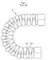
- a cable drag chain "A" disclosed in the specification of Japanese Patent Application No. 2000-278471 previously filed by the present inventor includes a pair of connector pins A34 and pin hole portions A35 at a front end portion A32 and a rear end portion A33 in a plurality of tubular intermediate frames A3 respectively as shown in FIGS. 4 and 5. Then, the end surface of each of the front and rear end portions A32 and A33 is formed as a stopper surface, which limits a bending angle, and the connector pin portion A34 and the pin hole portion A35 of the adjacent intermediate frame A3 are engaged to each other thereby connecting a plurality of intermediate frames A3. At the same time an outer periphery of the connected portion of the adjacent intermediate frame A3 is covered with a detachable tubular outer frame A4 to close a gap between the adjacent intermediate frames A3.
- the upper and lower tubular member halves are made of a metallic material and the small tube member are molded of a synthetic resin, the metallic material shaves the synthetic resin during sliding and a large amount of wear powder is produced. Further, since the metallic material is used the holding device becomes heavier than that molded of only a synthetic resin. Additionally since a portion of a metallic material and a portion of a synthetic resin collide with each other during moving the support device, a high noise is generated. Furthermore, since the upper and lower tube member halves on the outermost periphery is made of metal the noise that the upper frame hits a floor surface during the movement of the device becomes higher.
- an intermediate frame A3 is formed by a thick hollow rectangular tube body of a synthetic resin and there is a troublesome problem that the cable or the hose cannot be inserted during maintenance and repair as shown in FIG. 5(a).
- a thin tongue piece A47 provided on the outer frame A4 is engaged in a groove portion A36 provided on the outer peripheral surface of the intermediate frame A3 to close the gap of the connecting portion.
- the thin tongue piece A47 makes the contact conditions with the intermediate frame A3 insufficient and the sealing degree cannot be exerted sufficiently.
- the objects of the present invention is to solve the above-mentioned problems and to provide a closed cable drag chain, which is capable of preventing the contact wear powder generated in the holding and guiding the cable or the like from being scattered by reliably closing the cable or the like, and wherein the assembling, maintenance and repair are easy while having light weight and low noise.
- a closed cable drag chain into which a cable or the like is inserted to be held and guided in conditions where a number of intermediate frames are articulately connected to each other, an outer frame including a removable opening/closing frame structure fit-covers a coupled portion of the adjacent intermediate frames to close the coupling gaps respectively thereby engaging it in a tubular shape
- said intermediate frame comprises an intermediate frame body in which a cable holding groove was provided and an opening/closing lid member fitted into said cable holding groove
- said intermediate frame body includes lower open end surfaces, which abut with each other on the chain bend inner peripheral side to hold a required bending position of the chain and upper open end surfaces, which abut with each other on the chain bend outer peripheral side to hold a straightly extended position of the chain.
- a closed cable drag chain according to claim 2 further solves the above-mentioned problems by that fact that an elastic sealed portion, which closely fits said outer frame and said intermediate frame are formed on the inside of the front end and the inside of the rear end of the outer frame in addition to the configuration of claim 1.
- a closed cable drag chain according to claims 3 and 4 further solves the above-mentioned problems by the fact that said outer frame is relatively movably connected to said opening/closing lid member while including an engagement piece, which is movably engaged in an engagement portion protruded on the opening/closing lid member in the coupling direction of the chain in addition to the configuration according to claim 1 or 2.
- a closed cable drag chain according to claims 5, 6, 7 and 8 further solves the above-mentioned problems by the fact that said intermediate frame and outer frame are formed of a synthetic resin in addition to the configuration according to claims 1 to 4.
- the intermediate frame used in the present invention comprises an intermediate frame body in which a cable holding groove is provided and an opening/closing lid member, which is fitted into said cable holding groove.
- the intermediate frames forms a tubular coupling structure in which they were articulately connected to each other and has a form in which a cable or the like is inserted and can be held and guided, any annular forms having cross-sections such as a circular cross-section, an oval cross-section, a rectangular cross-section and the like may be used.
- a number of intermediate frames in the present invention may be used if they are articulately connected to each other in a coupling structure.
- the concrete connection structures a connecting structure in which connecting pin portions of the adjacent frames and the pin hole portions of the adjacent intermediate frames were fitted to each other, a connecting structure in which the pin hole portions of the adjacent intermediate frames were connected to a connecting pin of another part or the like can be adopted.
- any of the opening/closing frame structures which can be split or opened/closed up and down or left and right, may be used. Further, if an opening/closing mechanism including a snap locking portion on one hand and including a hinge portion on the other hand is adopted, a simple opening/closing operation can be attained.
- the elastic sealed portion formed inside the front end and inside the rear end of said outer frame can closely fits the outer frame and the intermediate frame, even a sealing form integrally molded by a multi-components injection molding process may be used and a sealing form in which an elastic sealing member was adhered with adhesive or the like may also be used.
- the engagement structure of the engagement piece formed on said outer frame and the engagement portion protruded on the opening/closing lid member is a structure that can relatively movably connect the outer frame to the opening/closing lid member, any engagement structure may be used. Even if, for example, said engagement structure is one in which the engagement portion is formed of a stopping projection and an engagement hole, which is movably engaged with this stopping projection in the coupling direction, is provided in an engagement piece, it may be used.
- any material may be used. Nevertheless, synthetic resins such as acryl so called as engineering plastics having excellent wear resistance and lubricating properties, polycarbonate, nylon 6, nylon 66, nylon 46, all aromatic nylons and the like are preferably used. Further, when strength is required, fiber reinforced plastics is preferred.
- the closed cable drag chain sequentially causes portions exhibiting required bending positions of a number of adjacent intermediate frames coupled in a tubular shape to sequentially displace in accordance with the mobile positions of mobile portions while lower open end surfaces formed on the intermediate frame bodies of the intermediate frames abut on each other on a chain bend inner peripheral side thereby ensuring a required bending radius, whereby the cable or the like can be moved together with the mobile portion of the machine while being held and guided.
- upper open end surfaces formed on the intermediate frame bodies of the intermediate frames abut on each other on a chain bend outer peripheral side at mobile positions where said adjacent intermediate frames do not require a required bending position, whereby the drag chain allows the cable or the like to be inserted and held while maintaining a straightly extended position.
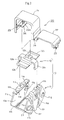
- FIG. 1 is an enlarged perspective view of a configuration unit of a closed cable drag chain, which is one Example of the present invention
- FIG. 2 is a disassembled view of the configuration unit shown in FIG. 1
- FIG. 3 is a side view of a closed cable drag chain formed by connecting the configuration units shown in FIG. 1 to each other.
- the closed cable drag chain of the present Example is formed by connecting a number of configuration units to each other as shown in FIGS. 1 and 2 to a tubular form. More specifically, as shown in FIG. 3, a number of intermediate frames 10 made of a synthetic resin are articulately connected to each other to form a coupled tube and by fit-covering a coupling portion between the intermediate frames with an outer frame 20 made of a synthetic resin to close coupling gaps S respectively a basic structure in which the cable or the like C are inserted, held and guided is included.
- the intermediate frame 10 of the synthetic resin of the present Example comprises an intermediate frame body 11 in which a cable holding groove 11a for inserting the cable or the like C therein was provided and an opening/closing lid member 12 which is fitted into the cable holding groove 11a as shown in FIG. 2.
- the frame form is an annular form having a rectangular cross-section.
- the intermediate body 11 includes a lower open end surface 11 b which holds a required bent position by abutting therewith on a bent inner peripheral side of the chain and an upper open end surface 11c which holds a straightly extended position by abutting therewith on a bent outer peripheral side of the chain.
- the opening/closing lid member 12 which is fitted into said cable holding groove 11a, is elastically engaged in opposite side wall engagement portions 11d and 11d by reversed- U-shaped locking arms 12a and 12a extending on both sides and exerting spring plate effects inwardly, and is fitted in opposed step portions 11e each provided on the upper end of the cable holding groove 11a so that the flowing out of contact wear powder generated within the cable holding groove 11a from the coupling portion is prevented.
- said opening/closing lid member 12 includes a bend-limiting portion 12b, which abuts on a chain on the chain bending outer peripheral side as well as the upper open end surface 11c formed on the intermediate body 11 of the intermediate frame 10 to helpfully limit the bending of the chain so that it can maintain the straight extended position, at a mobile position where a required bending position is not needed.
- said intermediate frames 10 can be articulately connected to each other to be coupled to a tubular structure by adopting a connected structure wherein connector pin portions 11f protruded on the intermediate frame body 11 and the adjacent pin hole portions 11g bored in the intermediate frame body 11 are fitted to each other, whereby assembling and disassembling a drag chain can be easily performed without using another part of the connector pin.
- a connected structure in which the adjacent pin hole portions bored in the intermediate frame portions 11 were reliably connected to each other with another part of a connecting pin may be adopted.
- the outer periphery of said intermediate frame 10 is provided with fitting grooves 11h, which are fitted to and covered by the outer frame 20 at coupling portions between adjacent intermediate frames 10 to close the coupling gaps S respectively.
- an outer frame 20 made of a synthetic resin of the present Example includes an opening/closing frame structure comprising an upper side outer frame 21 and a lower side outer frame 22, both of which can be disassembled from a coupling portion between the adjacent intermediate frames 10, and adopts a integral piece type frame which is split to open in the up and down directions at a snap locking portion 23 provided on one end, where these upper side outer frame 21 and lower side outer frame 22 are connected to each other, and at a hinge portion 24 provided on the other end.
- outer frame 20 of a synthetic resin of the present Example an integral type outer frame which can be split to open itself left and right by including an opening/closing structure comprising a right outer frame and a left outer frame may be adopted.
- An elastic sealed portion 25 is formed by adhering an elastic sealing material to the inside of the front end of said outer frame 20 and the inside of the rear end thereof so that the closed fitting of the intermediate frame 10 can be performed even in any bent conditions and the sealing degree between the intermediate frame 10 and the outer frame 20 is improved.
- the diffusion of dust such as contact wear powder generated on holding and guiding the cable or the like C is reliably blocked and sliding noise and contact noise, which are likely to occur between the intermediate frame 10 and the outer frame 20, are absorbed.
- the sealing degree can be improved by the use of elastic deformation of the synthetic resin and the collision speed of the adjacent intermediate frames 10 is reduced to lower the collision noise by sliding resistance between the synthetic resins generated on bending of the intermediate frame 10.
- a tongue-shaped engagement piece 26 having a bored engagement hole 26a is provided in said outer frame 20 so that it is movably engaged in the opening/closing lid member 12 in an engagement direction of the engagement piece 26. Further, the engagement hole 26a of the engagement piece 26 is relatively movably connected to an engagement portion 12c comprising a stopping protrusion protruded on the opening/closing member 12.
- the sliding resistance generated on the intermediate frame body 11 reduces the collision speed of the adjacent intermediate frame bodies 11 whereby these collision noises can be lowered.
- the engagement piece 26 of the outer frame 20 is integrally connected to the engagement portion 12c of the opening/closing member 12.
- the upper opened end portion 11c formed in the intermediate frame body 11 of the intermediate frame 10 and the bend limiting end portion 12b of the opening/closing lid member 12 inserts the cable or the like C to hold it while abutting with the chain on the respective chain bending outer peripheral side and maintaining the straight extended position at a moving position where the adjacent frames 10 do not require a required bending position.
- the thus obtained closed cable drag chain of the present Example can remove the intermediate frame 20 and open/close the opening/closing lid member 12 without disassembling the engagement of the adjacent intermediate frames 10 by including the above-mentioned chain structure.
- the assembling of the chain in inserting a cable or the like C in the chain and maintenance and repair not only become easy but also the diffusion of the contact wear powder, which is likely to occur in holding and guiding the cable or the like C can be reliably prevented and the sliding noise and contact noise, which are generated between members, and the collision noise, which is generated between the adjacent intermediate bodies 11, as well as the hitting noise, which is generated in hitting the moving surface of the cable can be removed.
- weight reduction of the chain and cost reduction can be realized resulting in significant effects.
- the present invention is not limited to the above-described Examples if the features of the present invention are not lost, and for example, the intermediate frame 10 and the outer frame 20 may use any forms other than those described above.
- the intermediate frame comprises an intermediate frame body in which a cable holding groove was provided and an opening/closing lid member fitted into said cable holding groove
- the outer frame includes an opening/closing frame structure removable from the coupling portion of the adjacent intermediate frames.
- the opening/closing lid member can be freely opened/closed at an upper position of the intermediate frame body without simultaneously operating the coupling of the adjacent intermediate frames and the mounting/dismounting of the outer frame unlike conventional cases. Therefore, even after the drag chain was attached to a mobile machine such as a machine tool, an electronic device, a civil engineering machinery, a transfer system or the like, a cable or the like can be easily inserted into the drag chain to assemble it. As a result the cable or the like in a cable holding groove can be easily checked and repaired during its maintenance.
- the intermediate frame includes lower open end surfaces, which abut with each other on the chain bend inner peripheral side to hold a required bending position of the chain and upper open end surface, which abut with each other on the chain bend outer peripheral side to hold a straightly extended position of the chain.
- the inserted state of the cable or the like in the chain can be stabilized and held while the upper open end surface formed in the intermediate body of the intermediate frame maintains a straightly extended position.
- the sealing degree between the outer frame and the intermediate frame is improved by the fact that an elastic sealed portion, which closely fits the outer frame and the intermediate frame are formed on the inside of the front end and the inside of the rear end of the outer frame.
- an elastic sealed portion which closely fits the outer frame and the intermediate frame are formed on the inside of the front end and the inside of the rear end of the outer frame.
Landscapes
- Engineering & Computer Science (AREA)
- General Engineering & Computer Science (AREA)
- Mechanical Engineering (AREA)
- Electric Cable Arrangement Between Relatively Moving Parts (AREA)
- Details Of Indoor Wiring (AREA)
- Installation Of Indoor Wiring (AREA)
Abstract
Description
- 10 ...
- Intermediate frame
- 11 ...
- Intermediate frame body
- 11a ...
- Cable holding groove
- 11b ...
- Lower open end surface
- 11c ...
- Upper open end surface
- 11d ...
- Side wall engagement portion
- 11e ...
- Step portion
- 11f ...
- Connecting pin portion
- 11g ...
- Pin hole portion
- 11h ...
- Fitting groove
- 12 ...
- Opening/closing lid member
- 12a ...
- Locking arm
- 12b ...
- Bend limiting end portion
- 12c ...
- Engagement portion
- 20 ...
- Outer frame
- 21 ...
- Upper outer frame
- 22 ...
- Lower outer frame
- 23 ...
- Snap locking portion
- 24 ...
- Hinge portion
- 25 ...
- Elastic sealed portion
- 26 ...
- Engagement piece
- 26a ...
- Engagement hole
- C ...
- Cable or the like
- S ...
- Coupling gap
Claims (8)
- A closed cable drag chain into which a cable or the like is inserted to be held and guided in conditions where a number of intermediate frames are articulately connected to each other, an outer frame including a removable opening/closing frame structure fit-covers a coupled portion of the adjacent intermediate frames to close the coupling gaps respectively thereby engaging it in a tubular shape, is characterized in that
said intermediate frame comprises an intermediate frame body in which a cable holding groove was provided and an opening/closing lid member fitted into said cable holding groove, and said intermediate frame body includes lower open end surfaces, which abut with each other on the chain bend inner peripheral side to hold a required bending position of the chain and upper open end surfaces, which abut with each other on the chain bend outer peripheral side to hold a straight extended position of the chain. - A closed cable drag chain according to claim 1 characterized in that elastic sealed portions, which closely fit said outer frame and said intermediate frame, are formed on the inside of the front end and the inside of the rear end of the outer frame.
- A closed cable drag chain according to claim 1 characterized in that said outer frame is relatively movably connected to said opening/closing lid member while including an engagement piece, which is movably engaged in an engagement portion protruded on the opening/closing lid member in the coupling direction of the chain.
- A closed cable drag chain according to claim 2 characterized in that said outer frame is relatively movably connected to said opening/closing lid member while including an engagement piece, which is movably engaged in an engagement portion protruded on the opening/closing lid member in the coupling direction of the chain.
- A closed cable drag chain according to claim 1 characterized in that said intermediate frame and outer frame are formed of a synthetic resin.
- A closed cable drag chain according to claim 2 characterized in that said intermediate frame and outer frame are formed of a synthetic resin.
- A closed cable drag chain according to claim 3 characterized in that said intermediate frame and outer frame are formed of a synthetic resin.
- A closed cable drag chain according to claim 4 characterized in that said intermediate frame and outer frame are formed of a synthetic resin.
Applications Claiming Priority (2)
| Application Number | Priority Date | Filing Date | Title |
|---|---|---|---|
| JP2001377830 | 2001-12-11 | ||
| JP2001377830A JP3349148B1 (en) | 2001-12-11 | 2001-12-11 | Closed cable drag chain |
Publications (3)
| Publication Number | Publication Date |
|---|---|
| EP1319865A2 true EP1319865A2 (en) | 2003-06-18 |
| EP1319865A3 EP1319865A3 (en) | 2003-07-23 |
| EP1319865B1 EP1319865B1 (en) | 2005-07-06 |
Family
ID=19185704
Family Applications (1)
| Application Number | Title | Priority Date | Filing Date |
|---|---|---|---|
| EP02025995A Expired - Lifetime EP1319865B1 (en) | 2001-12-11 | 2002-11-21 | Closed cable drag chain |
Country Status (4)
| Country | Link |
|---|---|
| US (1) | US6773297B2 (en) |
| EP (1) | EP1319865B1 (en) |
| JP (1) | JP3349148B1 (en) |
| DE (1) | DE60204937T2 (en) |
Cited By (2)
| Publication number | Priority date | Publication date | Assignee | Title |
|---|---|---|---|---|
| EP1463176A1 (en) * | 2003-03-25 | 2004-09-29 | Tsubakimoto Chain Co. | Cable or the like protection and guide device |
| ITTO20110502A1 (en) * | 2011-06-08 | 2012-12-09 | Soilmec Spa | SUPPORT AND GUIDE DEVICE FOR POWER LINES FOR DISCAVOUS DEVICES. |
Families Citing this family (51)
| Publication number | Priority date | Publication date | Assignee | Title |
|---|---|---|---|---|
| JP3717071B2 (en) | 2002-11-05 | 2005-11-16 | 株式会社椿本チエイン | Sealed cable drag chain |
| DE102004022512A1 (en) * | 2004-05-05 | 2005-12-01 | Kabelschlepp Gmbh | Chain link for an energy supply chain and energy supply chain with extended usage cross-section |
| JP4592583B2 (en) * | 2005-12-26 | 2010-12-01 | ローランドディー.ジー.株式会社 | Cable protection guide device for large printers |
| DE102006042544A1 (en) * | 2006-09-11 | 2008-03-27 | Poly-Clip System Gmbh & Co Kg | Filling device for a flowable filling medium |
| US7966819B2 (en) * | 2006-09-26 | 2011-06-28 | Parker-Hannifin Corporation | Vibration damper for fuel injector |
| JP4368886B2 (en) | 2006-11-27 | 2009-11-18 | 株式会社椿本チエイン | Sealed cable protection guide device |
| US7384299B1 (en) | 2007-03-19 | 2008-06-10 | International Business Machines Corporation | Self positioning, latchable cable trough |
| JP4338746B2 (en) * | 2007-04-27 | 2009-10-07 | 株式会社椿本チエイン | Cable protection guide device |
| US11294135B2 (en) | 2008-08-29 | 2022-04-05 | Corning Optical Communications LLC | High density and bandwidth fiber optic apparatuses and related equipment and methods |
| US8452148B2 (en) | 2008-08-29 | 2013-05-28 | Corning Cable Systems Llc | Independently translatable modules and fiber optic equipment trays in fiber optic equipment |
| ATE534049T1 (en) | 2009-02-24 | 2011-12-15 | Ccs Technology Inc | CABLE HOLDING DEVICE OR ARRANGEMENT FOR USE WITH A CABLE |
| US8699838B2 (en) | 2009-05-14 | 2014-04-15 | Ccs Technology, Inc. | Fiber optic furcation module |
| US9075216B2 (en) | 2009-05-21 | 2015-07-07 | Corning Cable Systems Llc | Fiber optic housings configured to accommodate fiber optic modules/cassettes and fiber optic panels, and related components and methods |
| WO2010148336A1 (en) | 2009-06-19 | 2010-12-23 | Corning Cable Systems Llc | High density and bandwidth fiber optic apparatuses and related equipment and methods |
| US8712206B2 (en) * | 2009-06-19 | 2014-04-29 | Corning Cable Systems Llc | High-density fiber optic modules and module housings and related equipment |
| US20110129186A1 (en) * | 2009-11-30 | 2011-06-02 | Lewallen C Paul | Fiber Optic Module Assembly and Associated Methods |
| US8625950B2 (en) | 2009-12-18 | 2014-01-07 | Corning Cable Systems Llc | Rotary locking apparatus for fiber optic equipment trays and related methods |
| US8992099B2 (en) | 2010-02-04 | 2015-03-31 | Corning Cable Systems Llc | Optical interface cards, assemblies, and related methods, suited for installation and use in antenna system equipment |
| US8913866B2 (en) | 2010-03-26 | 2014-12-16 | Corning Cable Systems Llc | Movable adapter panel |
| AU2011265751B2 (en) | 2010-04-16 | 2015-09-10 | Corning Optical Communications LLC | Sealing and strain relief device for data cables |
| US9720195B2 (en) | 2010-04-30 | 2017-08-01 | Corning Optical Communications LLC | Apparatuses and related components and methods for attachment and release of fiber optic housings to and from an equipment rack |
| US8660397B2 (en) | 2010-04-30 | 2014-02-25 | Corning Cable Systems Llc | Multi-layer module |
| US9519118B2 (en) | 2010-04-30 | 2016-12-13 | Corning Optical Communications LLC | Removable fiber management sections for fiber optic housings, and related components and methods |
| US9632270B2 (en) | 2010-04-30 | 2017-04-25 | Corning Optical Communications LLC | Fiber optic housings configured for tool-less assembly, and related components and methods |
| US9075217B2 (en) | 2010-04-30 | 2015-07-07 | Corning Cable Systems Llc | Apparatuses and related components and methods for expanding capacity of fiber optic housings |
| US8705926B2 (en) | 2010-04-30 | 2014-04-22 | Corning Optical Communications LLC | Fiber optic housings having a removable top, and related components and methods |
| US8879881B2 (en) | 2010-04-30 | 2014-11-04 | Corning Cable Systems Llc | Rotatable routing guide and assembly |
| US8718436B2 (en) | 2010-08-30 | 2014-05-06 | Corning Cable Systems Llc | Methods, apparatuses for providing secure fiber optic connections |
| US9279951B2 (en) | 2010-10-27 | 2016-03-08 | Corning Cable Systems Llc | Fiber optic module for limited space applications having a partially sealed module sub-assembly |
| US8662760B2 (en) | 2010-10-29 | 2014-03-04 | Corning Cable Systems Llc | Fiber optic connector employing optical fiber guide member |
| US9116324B2 (en) | 2010-10-29 | 2015-08-25 | Corning Cable Systems Llc | Stacked fiber optic modules and fiber optic equipment configured to support stacked fiber optic modules |
| WO2012074982A1 (en) | 2010-11-30 | 2012-06-07 | Corning Cable Systems Llc | Fiber device holder and strain relief device |
| WO2012106510A2 (en) | 2011-02-02 | 2012-08-09 | Corning Cable Systems Llc | Dense fiber optic connector assemblies and related connectors and cables suitable for establishing optical connections for optical backplanes in equipment racks |
| US9008485B2 (en) | 2011-05-09 | 2015-04-14 | Corning Cable Systems Llc | Attachment mechanisms employed to attach a rear housing section to a fiber optic housing, and related assemblies and methods |
| EP2726928A1 (en) | 2011-06-30 | 2014-05-07 | Corning Cable Systems LLC | Fiber optic equipment assemblies employing non-u-width-sized housings and related methods |
| US8953924B2 (en) | 2011-09-02 | 2015-02-10 | Corning Cable Systems Llc | Removable strain relief brackets for securing fiber optic cables and/or optical fibers to fiber optic equipment, and related assemblies and methods |
| US9038832B2 (en) | 2011-11-30 | 2015-05-26 | Corning Cable Systems Llc | Adapter panel support assembly |
| KR101358451B1 (en) * | 2012-04-19 | 2014-02-05 | 주식회사 코닥트 | Link combination structure for cable carrier |
| US9250409B2 (en) | 2012-07-02 | 2016-02-02 | Corning Cable Systems Llc | Fiber-optic-module trays and drawers for fiber-optic equipment |
| JP2014027749A (en) * | 2012-07-25 | 2014-02-06 | Disco Abrasive Syst Ltd | Cable guide |
| US9042702B2 (en) | 2012-09-18 | 2015-05-26 | Corning Cable Systems Llc | Platforms and systems for fiber optic cable attachment |
| EP2725397B1 (en) | 2012-10-26 | 2015-07-29 | CCS Technology, Inc. | Fiber optic management unit and fiber optic distribution device |
| US8985862B2 (en) | 2013-02-28 | 2015-03-24 | Corning Cable Systems Llc | High-density multi-fiber adapter housings |
| DE202013101460U1 (en) | 2013-04-05 | 2013-04-22 | Igus Gmbh | Cable routing from multiaxial bendable links |
| DE102013208527A1 (en) * | 2013-05-08 | 2014-11-13 | Siemens Aktiengesellschaft | Kink protection for a cable harness |
| TWI689669B (en) | 2014-09-18 | 2020-04-01 | 德商伊格斯公司 | Line guide device, in particular for clean room applications, shell portions and support rib structure for same |
| DE202015101341U1 (en) | 2015-03-16 | 2015-03-20 | Igus Gmbh | Energy guiding chain with holder for an external line and corresponding receiving element |
| US10686307B2 (en) * | 2015-12-14 | 2020-06-16 | Ppc Broadband, Inc. | Flexible channel molding assemblies |
| DE102016116991A1 (en) | 2016-09-09 | 2018-03-15 | Sartorius Stedim Biotech Gmbh | Anti-kink device for a hose |
| US11326672B2 (en) * | 2020-09-23 | 2022-05-10 | Craig Louis Althen | Continuously variable, non-friction, drive chain |
| CN112091866B (en) * | 2020-10-12 | 2024-07-19 | 浙江金福隆机床附件有限公司 | Drag chain apron quick assembly disassembly integral type appurtenance |
Citations (2)
| Publication number | Priority date | Publication date | Assignee | Title |
|---|---|---|---|---|
| JPS6215008B2 (en) | 1980-04-30 | 1987-04-06 | Kabelschlepp Gmbh | |
| JP2000278471A (en) | 1999-03-29 | 2000-10-06 | Minolta Co Ltd | Remote diagnosis system for image reader |
Family Cites Families (14)
| Publication number | Priority date | Publication date | Assignee | Title |
|---|---|---|---|---|
| EP0038952B1 (en) * | 1980-04-30 | 1984-05-16 | Kabelschlepp Gesellschaft mit beschränkter Haftung | Energy line support |
| DE3507200A1 (en) * | 1985-03-01 | 1986-09-04 | Kabelschlepp Gmbh, 5900 Siegen | POWER SUPPLY CHAIN |
| US5215338A (en) * | 1985-04-09 | 1993-06-01 | Tsubakimoto Chain Co. | Flexible supporting sheath for cables and the like |
| US5197767A (en) * | 1985-04-09 | 1993-03-30 | Tsubakimoto Chain Co. | Flexible supporting sheath for cables and the like |
| US4834594A (en) | 1987-04-06 | 1989-05-30 | Fansteel Inc. | Drill steel drive unit |
| DE9109422U1 (en) * | 1991-07-30 | 1991-10-02 | Shih, Ta-Feng, Changhua City | Rectangular protective tube for a flexible cable |
| JPH0615008A (en) | 1992-06-30 | 1994-01-25 | Olympus Optical Co Ltd | Microwave hyperthermia thrapeutic device |
| DE4302757C1 (en) * | 1993-02-01 | 1994-03-17 | Igus Gmbh | Electrical cable guide unit formed by two types of plastic element - that have linkage connection points that are engaged in snap action operation and allow some movement. |
| DE9318441U1 (en) * | 1993-12-02 | 1994-02-03 | Shih, Ta-Feng, Chang-Hua | Rectangular protective tube for a flexible cable |
| US5933557A (en) * | 1996-11-19 | 1999-08-03 | Siecor Corporation | Multi-link boot assembly for cable connector |
| US6039081A (en) * | 1997-02-12 | 2000-03-21 | Pmi Industries, Inc. | Articulated bend limiter |
| KR100412249B1 (en) * | 1999-04-19 | 2003-12-31 | 이구스 슈프리츠구쓰타일레 퓌어 디 인두스트리 게엠베하 | Conduit carrier chain |
| JP3356758B2 (en) | 2000-09-13 | 2002-12-16 | 株式会社椿本チエイン | Cable drag chain |
| US6575654B2 (en) * | 2001-07-20 | 2003-06-10 | Adc Telecommunications, Inc. | Flexible snap-together cable enclosure |
-
2001
- 2001-12-11 JP JP2001377830A patent/JP3349148B1/en not_active Expired - Fee Related
-
2002
- 2002-11-21 DE DE60204937T patent/DE60204937T2/en not_active Expired - Fee Related
- 2002-11-21 EP EP02025995A patent/EP1319865B1/en not_active Expired - Lifetime
- 2002-11-22 US US10/301,963 patent/US6773297B2/en not_active Expired - Fee Related
Patent Citations (2)
| Publication number | Priority date | Publication date | Assignee | Title |
|---|---|---|---|---|
| JPS6215008B2 (en) | 1980-04-30 | 1987-04-06 | Kabelschlepp Gmbh | |
| JP2000278471A (en) | 1999-03-29 | 2000-10-06 | Minolta Co Ltd | Remote diagnosis system for image reader |
Cited By (5)
| Publication number | Priority date | Publication date | Assignee | Title |
|---|---|---|---|---|
| EP1463176A1 (en) * | 2003-03-25 | 2004-09-29 | Tsubakimoto Chain Co. | Cable or the like protection and guide device |
| US6864425B2 (en) | 2003-03-25 | 2005-03-08 | Tsubakimoto Chain Co. | Cable or the like protection and guide device |
| ITTO20110502A1 (en) * | 2011-06-08 | 2012-12-09 | Soilmec Spa | SUPPORT AND GUIDE DEVICE FOR POWER LINES FOR DISCAVOUS DEVICES. |
| EP2532791A1 (en) * | 2011-06-08 | 2012-12-12 | Soilmec S.p.A. | Supporting and guiding device for power lines for excavation tools |
| US8997448B2 (en) | 2011-06-08 | 2015-04-07 | Soilmec S.P.A. | Supporting and guiding device for power lines for excavation devices |
Also Published As
| Publication number | Publication date |
|---|---|
| JP3349148B1 (en) | 2002-11-20 |
| EP1319865A3 (en) | 2003-07-23 |
| US6773297B2 (en) | 2004-08-10 |
| DE60204937D1 (en) | 2005-08-11 |
| JP2003176854A (en) | 2003-06-27 |
| US20030109168A1 (en) | 2003-06-12 |
| EP1319865B1 (en) | 2005-07-06 |
| DE60204937T2 (en) | 2006-04-20 |
Similar Documents
| Publication | Publication Date | Title |
|---|---|---|
| EP1319865B1 (en) | Closed cable drag chain | |
| EP1351362B1 (en) | Protective guide for flexible elongated article | |
| KR100447679B1 (en) | Cable Drag Chain | |
| US7428808B2 (en) | Cable or the like protection and guide device | |
| KR101443896B1 (en) | anti-vibration device | |
| US7637092B2 (en) | Cable protection and guide device | |
| TW548382B (en) | Protective guide for cables and the like | |
| KR101123566B1 (en) | Cable or the like protection and guide device | |
| CA3179490C (en) | Insertion tool with flexible spine | |
| JP5541746B2 (en) | Cable protection guide device | |
| US20130032677A1 (en) | Cable protection and guide apparatus | |
| JP4136905B2 (en) | Horizontally installed cable protection guide device | |
| EP1094585B1 (en) | Cable drag chain | |
| JP2004159406A (en) | Closed cable drag chain | |
| US7454891B2 (en) | Cable protection and guide device | |
| KR100863661B1 (en) | Cable protection and guide device | |
| US12085147B2 (en) | Line guide with support chain for clean room applications and support chain thereof | |
| KR20040047642A (en) | Cable or the like protection and guide device | |
| KR200370351Y1 (en) | A cable bearer | |
| JP2000351897A (en) | Hinge member | |
| EP1995734A3 (en) | Optical disc package | |
| CN223497725U (en) | Elastic hinge | |
| CN217271845U (en) | Sleeve joint for automobile inhaul cable assembly | |
| CN115807975B (en) | Air guide door assembly and air conditioner | |
| JP4827786B2 (en) | Cable protection guide device |
Legal Events
| Date | Code | Title | Description |
|---|---|---|---|
| PUAI | Public reference made under article 153(3) epc to a published international application that has entered the european phase |
Free format text: ORIGINAL CODE: 0009012 |
|
| PUAL | Search report despatched |
Free format text: ORIGINAL CODE: 0009013 |
|
| AK | Designated contracting states |
Designated state(s): AT BE BG CH CY CZ DE DK EE ES FI FR GB GR IE IT LI LU MC NL PT SE SK TR |
|
| AX | Request for extension of the european patent |
Extension state: AL LT LV MK RO SI |
|
| AK | Designated contracting states |
Designated state(s): AT BE BG CH CY CZ DE DK EE ES FI FR GB GR IE IT LI LU MC NL PT SE SK TR |
|
| AX | Request for extension of the european patent |
Extension state: AL LT LV MK RO SI |
|
| 17P | Request for examination filed |
Effective date: 20030716 |
|
| RAP1 | Party data changed (applicant data changed or rights of an application transferred) |
Owner name: TSUBAKIMOTO CHAIN CO. |
|
| AKX | Designation fees paid |
Designated state(s): DE FR GB IT |
|
| 17Q | First examination report despatched |
Effective date: 20040312 |
|
| GRAP | Despatch of communication of intention to grant a patent |
Free format text: ORIGINAL CODE: EPIDOSNIGR1 |
|
| GRAS | Grant fee paid |
Free format text: ORIGINAL CODE: EPIDOSNIGR3 |
|
| GRAA | (expected) grant |
Free format text: ORIGINAL CODE: 0009210 |
|
| AK | Designated contracting states |
Kind code of ref document: B1 Designated state(s): DE FR GB IT |
|
| REG | Reference to a national code |
Ref country code: GB Ref legal event code: FG4D |
|
| REF | Corresponds to: |
Ref document number: 60204937 Country of ref document: DE Date of ref document: 20050811 Kind code of ref document: P |
|
| PGFP | Annual fee paid to national office [announced via postgrant information from national office to epo] |
Ref country code: FR Payment date: 20051220 Year of fee payment: 4 |
|
| ET | Fr: translation filed | ||
| PLBE | No opposition filed within time limit |
Free format text: ORIGINAL CODE: 0009261 |
|
| STAA | Information on the status of an ep patent application or granted ep patent |
Free format text: STATUS: NO OPPOSITION FILED WITHIN TIME LIMIT |
|
| 26N | No opposition filed |
Effective date: 20060407 |
|
| GBPC | Gb: european patent ceased through non-payment of renewal fee |
Effective date: 20061121 |
|
| REG | Reference to a national code |
Ref country code: FR Ref legal event code: ST Effective date: 20070731 |
|
| PG25 | Lapsed in a contracting state [announced via postgrant information from national office to epo] |
Ref country code: GB Free format text: LAPSE BECAUSE OF NON-PAYMENT OF DUE FEES Effective date: 20061121 |
|
| PG25 | Lapsed in a contracting state [announced via postgrant information from national office to epo] |
Ref country code: FR Free format text: LAPSE BECAUSE OF NON-PAYMENT OF DUE FEES Effective date: 20061130 |
|
| PGFP | Annual fee paid to national office [announced via postgrant information from national office to epo] |
Ref country code: DE Payment date: 20081114 Year of fee payment: 7 |
|
| PGFP | Annual fee paid to national office [announced via postgrant information from national office to epo] |
Ref country code: IT Payment date: 20081125 Year of fee payment: 7 |
|
| PG25 | Lapsed in a contracting state [announced via postgrant information from national office to epo] |
Ref country code: DE Free format text: LAPSE BECAUSE OF NON-PAYMENT OF DUE FEES Effective date: 20100601 |
|
| PG25 | Lapsed in a contracting state [announced via postgrant information from national office to epo] |
Ref country code: IT Free format text: LAPSE BECAUSE OF NON-PAYMENT OF DUE FEES Effective date: 20091121 |