EP1319845A2 - Flexible actuator - Google Patents
Flexible actuator Download PDFInfo
- Publication number
- EP1319845A2 EP1319845A2 EP02026588A EP02026588A EP1319845A2 EP 1319845 A2 EP1319845 A2 EP 1319845A2 EP 02026588 A EP02026588 A EP 02026588A EP 02026588 A EP02026588 A EP 02026588A EP 1319845 A2 EP1319845 A2 EP 1319845A2
- Authority
- EP
- European Patent Office
- Prior art keywords
- expanded hollow
- tube
- frame members
- actuator
- hollow portions
- Prior art date
- Legal status (The legal status is an assumption and is not a legal conclusion. Google has not performed a legal analysis and makes no representation as to the accuracy of the status listed.)
- Granted
Links
Images







Classifications
-
- B—PERFORMING OPERATIONS; TRANSPORTING
- B25—HAND TOOLS; PORTABLE POWER-DRIVEN TOOLS; MANIPULATORS
- B25J—MANIPULATORS; CHAMBERS PROVIDED WITH MANIPULATION DEVICES
- B25J9/00—Program-controlled manipulators
- B25J9/10—Program-controlled manipulators characterised by positioning means for manipulator elements
- B25J9/14—Program-controlled manipulators characterised by positioning means for manipulator elements fluid
- B25J9/142—Program-controlled manipulators characterised by positioning means for manipulator elements fluid comprising inflatable bodies
-
- B—PERFORMING OPERATIONS; TRANSPORTING
- B25—HAND TOOLS; PORTABLE POWER-DRIVEN TOOLS; MANIPULATORS
- B25J—MANIPULATORS; CHAMBERS PROVIDED WITH MANIPULATION DEVICES
- B25J15/00—Gripping heads and other end effectors
- B25J15/08—Gripping heads and other end effectors having finger members
- B25J15/12—Gripping heads and other end effectors having finger members with flexible finger members
-
- F—MECHANICAL ENGINEERING; LIGHTING; HEATING; WEAPONS; BLASTING
- F15—FLUID-PRESSURE ACTUATORS; HYDRAULICS OR PNEUMATICS IN GENERAL
- F15B—SYSTEMS ACTING BY MEANS OF FLUIDS IN GENERAL; FLUID-PRESSURE ACTUATORS, e.g. SERVOMOTORS; DETAILS OF FLUID-PRESSURE SYSTEMS, NOT OTHERWISE PROVIDED FOR
- F15B15/00—Fluid-actuated devices for displacing a member from one position to another; Gearing associated therewith
- F15B15/08—Characterised by the construction of the motor unit
- F15B15/10—Characterised by the construction of the motor unit the motor being of diaphragm type
- F15B15/103—Characterised by the construction of the motor unit the motor being of diaphragm type using inflatable bodies that contract when fluid pressure is applied, e.g. pneumatic artificial muscles or McKibben-type actuators
Definitions
- the present invention relates to a flexible actuator that can be used for driving a robot capable of gripping, pinching, or pushing and a pet robot that acts like an animal.
- known actuators for gripping an object include a cylindrical elastic body having a plurality of pressure chambers therein and adjust a fluid pressure applied to each pressure chamber to curve and deform the cylindrical elastic body (hereinafter referred to as the first prior art).
- an actuator different from the first prior art is also known in which a driving source and a pump are integrated into a hydraulic cylinder (hereinafter referred to as the second prior art).
- An actuator that operates as a robot finger of a robot must bend like a human finger, and enclose to grip a soft object such as a fruit or a paper cup, pinch a small object such as a screw with its tip, or bend to push a switch with its tip.
- a substantially even bending force is desirably produced throughout the finger.
- a bending force proportional to a distance from the tip is desirably produced in terms of moment. Reducing the bending force at the tip saves power for bending.
- the actuator entirely bends with a predetermined curvature to grip the object, and do not have a structure in which an appropriate bending force is produced at each part.
- it is difficult to configure an actuator capable of performing various operations such as enclosing to grip the soft object, pinching the small object, or pushing the switch with the tip, with appropriate gripping forces like the human finger.
- the second prior art is of the piston type, and requires many actuators and associated sensors or mechanisms to configure a flexible actuator, so that it is difficult to cause the actuator to operate as a robot finger.
- an operating fluid must be supplied to the pressure chamber, or a pump that discharges the operating fluid from the pressure chamber must be placed outside via a fluid tube (referred to as an operating tube in the specification of the prior art) which cannot provide a small actuator.
- a fluid tube referred to as an operating tube in the specification of the prior art
- a reservoir that stores the liquid is placed outside together with the pump.
- a main liquid chamber When the reservoir is above the pressure chamber (hereinafter referred to as a main liquid chamber) and when the reservoir is below the main liquid chamber, amounts of liquid supplied and discharged to and from the main liquid chamber by gravity change depending on changes in positions of the cylindrical elastic body.
- a main liquid chamber When the reservoir is above the pressure chamber (hereinafter referred to as a main liquid chamber) and when the reservoir is below the main liquid chamber, amounts of liquid supplied and discharged to and from the main liquid chamber by gravity change depending on changes in positions of the cylindrical elastic body.
- each change in the position of the cylindrical elastic body tends to cause a change in an amount of bending deformation.
- the present invention has been achieved to solve the above described problems in the prior art, andhas an object to provide a flexible actuator capable of gripping a soft object like a human finger and finely acting like an animal, and also avoiding a change in an amount of liquid moving between a reservoir and a main liquid chamber by gravity even if a liquid is used as an operating fluid, and keeping a constant amount of bending deformation even if the actuator changes its position.
- a flexible actuator according to the invention has the following configuration.
- the flexible actuator according to the invention includes: a long movable part that is bent by a liquid moving toward a main liquid chamber; a reservoir where the liquid moves to and from the main liquid chamber; a pump that moves the liquid between the reservoir and the main liquid chamber; and a pump driving unit that controls the pump,
- the movable part includes a long tube that forms the main liquid chamber, a plurality of frame members aligned at predetermined intervals along a length of the tube, and a resilient core member that holds the alignment of the frame members
- the tube is made of a flexible elastic material, and includes a plurality of flat expanded hollow portions provided at predetermined intervals along the length and a narrow hollow portion that communicates between the expanded hollow portions
- the plurality of frame members are formed by flat members and longitudinally hold the plurality of expanded hollow portions by the narrow hollow portion of the tube inserted into recesses or holes provided on sides abutting the coremember
- the movable part has a first
- the expanded hollow portion placed in the first bending portion has the large transverse cross sectional area
- the expanded hollow portion placed in the second bending portion has the small transverse cross sectional area, so that the first bending portion produces the large bending force and the second bending portion produces the small bending force simply by a fluid flowing into the tube to increase capacities of the expanded hollow portions, thus allowing operations different from those of a conventional actuator.
- the flexible actuator may be used as a robot finger or the like, and the expanded hollow portion at a base of the movable part as the first bending portion may have a largest transverse cross sectional area, with transverse cross sectional areas of the expanded hollow portions gradually decreasing toward a tip of the movable part, and the expanded hollow portion at the tip of the movable part as the second bending portion may have a smallest transverse cross sectional area.
- the base of the movable part that is a root of the robot finger produces a large bending force
- the tip of the movable part that is a tip of the robot finger produces a small bending force to bend. This allows the actuator to reliably enclose to grip a soft object, pinch a small object, or push a switch with the tip, and act like a human finger.
- the transverse cross sectional area of the expanded hollow portion placed in the second bending portion may be 30% to 80% of the transverse cross sectional area of the expanded hollow portion placed in the first bending portion.
- providing the second bending portion at the base prevents a large force to fold the base from being applied in gripping the object, thus allowing the object to be properly gripped. Further, an average sectional area at the tip that requires no large bending force is small, thus a total amount of hydraulic fluid required for bending decreases to allow quick bending and extension.
- the core member may be a member having gradually decreasing resilience from the base toward the tip of the movable part.
- the core member may be a tapered plate material in which a base has a large width, with widths gradually decreasing toward a tip, and the tip has a smallest width.
- the core member having the large width at the base prevents the bending force from concentrating on the base of the movable part, thus allowing the entire movable part to bend with an even curvature.
- the flexible actuator may be used as an actuator for massaging a shoulder, and the expanded hollow portion at a center along the length of the movable part as the first bending portion has a largest transverse cross sectional area, with transverse cross sectional areas of the expanded hollow portions gradually decreasing toward both ends along the length of the movable part, and the expanded hollow portions at the both ends of the movable part as the second bending portion have a smallest transverse cross sectional area.
- the flexible actuator with such a configuration When the flexible actuator with such a configuration is used as the actuator for massaging a shoulder by being applied to a human shoulder, a bending force of the expanded hollow portion at the center along the length increases to ensure massaging the shoulder.
- the transverse cross sectional area of the expanded hollow portion placed in the second bending portion may be approximately 60% of the transverse cross sectional area of the expanded hollow portion placed in the first bending portion.
- the core member may be a member having gradually decreasing resilience from the center along the length toward the both ends of the movable part.
- the core member may be a plate material in which a center along a length has a large width, with widths gradually decreasing toward both ends, and the both ends have a smallest width.
- the core member has low resilience at a portion where the moving part produces a small bending force.
- a flexible actuator including: a long movable part that is bent by a liquid moving toward a main liquid chamber; a reservoir where the liquid moves to and from the main liquid chamber; a pump that moves the liquid between the reservoir and the main liquid chamber; and a pump driving unit that controls the pump, wherein the movable part includes the main liquid chamber and the reservoir placed along a length, a plurality of frame members aligned at predetermined intervals along lengths of the main liquid chamber and the reservoir, and a resilient core member that holds the alignment of the frame members.
- the main liquid chamber and the reservoir are placed along a length in the movable part, so that even if a position of the movable part changes, an amount of fluid supplied from the reservoir to the main liquid chamber, and an amount of fluid discharged from the main liquid chamber to the reservoir by gravity do not change. Therefore, the change in the position of the movable part causes no change in an amount of bending deformation of the pump driving unit.
- the main liquid chamber and the reservoir are placed along the length to provide a small actuator.
- the reservoir may be formed by a tube made of an expandable and shrinkable elastic material, and includes a plurality of flat expanded hollow portions provided at predetermined intervals along the length, and a narrow hollow portion that communicates between the expanded hollow portions.
- the main liquid chamber may be formed by a tube made of an expandable and shrinkable elastic material, and includes a plurality of flat expanded hollow portions provided at predetermined intervals along the length, and a narrow hollow portion that communicates between the expanded hollow portions, and each expanded hollow portion of the main liquid chamber may be placed to longitudinally overlap each expanded hollow portion of the reservoir. This provides a smaller actuator.
- the plurality of frame members may be hollow members with cavities therein, and the expanded hollow portions of the reservoir may be placed in the cavities of the plurality of frame members.
- Each expanded hollow portion of the reservoir is placed in each cavity of the frame members, thus the fluid stored in the expanded hollow portions of the reservoir is not influenced by pressure due to bending of the movable part.
- the tube that forms the reservoir may be made of a flexible elastic material such that each expanded hollow portion of the tube can expand into the entire cavity.
- the plurality of frame members may include air holes that communicate between the cavities and an outside.
- the pump may be built in an actuator body integral with an end of the movable part.
- the pump is built in the actuator body to be compact, thus the actuator can be used as a pet robot with a simple appearance.
- a sensor that detects the amount of moving fluid may be placed in any of the pump, the main liquid chamber, or the reservoir, and the pump driving unit may control the pump based on information from the sensor.
- a flexible actuator including: a plurality of flat expanded hollow portions made of a flexible elastic material and provided at predetermined intervals along a length; a long tube in which a liquid chamber is formed by a connection tube that communicates between the plurality of expanded hollow portions and extends along the length; a plurality of flat frame members that longitudinally hold the plurality of expanded hollow portions of the tube with surface contact; and a connection that holds the adj acent frame members so as to swing against each other, wherein the actuator further includes at least one spring member for recovering rotating angle between the frame members, and the spring member is placed to produce a spring force in a compressing direction of the expanded hollow portions of the tube by the adjacent frame members.
- the actuator includes at least one spring member for recovering the rotating angle between the frame members, so that the spring member produces the spring force in the compressing direction of the plurality of expanded hollow portions to return the fluid from the tube, thus recovering to an upright condition.
- the spring member is independent, thus facilitating adjusting the resilience to minimize repulsion in large bending due to the resilience.
- a flexible actuator including: a first actuator that bends in a predetermined direction; and a second actuator joined to abase of the first actuator, wherein the first actuator includes: a plurality of flat expanded hollow portions made of a flexible elastic material and provided at predetermined intervals along a length; a long tube in which a liquid chamber is formed by a connection tube that communicates between the plurality of expanded hollow portions and extends along the length; a plurality of flat frame members that longitudinally hold the plurality of expanded hollow portions of the tube with surface contact; and a connection that holds the adjacent frame members so as to swing against each other, and the second actuator is placed between the frame member at the base of the first actuator and an actuator mounting portion, and the entire first actuator is slanted in a direction different from a bending direction of the first actuator.
- the first actuator that bends in a predetermined direction and the second actuator that slants the entire first actuator in the direction different from the bending direction of the first actuator are provided, thus allowing a position of a tip frame member corresponding to the finger tip to be changed when the actuator is used as a robot finger of a robot to precisely grip a small object.
- the first actuator may include at least one spring member for recovering rotating angle between the frame members, and the spring member may be placed to produce a spring force in a compressing direction of the expanded hollow portions of the tube by the adjacent frame members.
- the spring member produces the spring force in the compressing direction of the plurality of expanded hollow portion to return the fluid from the tube, thus recovering to the upright position.
- the spring member of the first actuator is independent, thus facilitating adjusting the resilience to minimize repulsion in large bending due to the resilience.
- ends of the spring member may be secured to both ends of the aligned frame members.
- the spring member does not locally and excessively extend to increase durability.
- Each of the frame members may include a guide that guides extension and shrinkage of the spring member. This prevents the spring member from being shifted in bending the flexible actuator.
- the frame members and the connection may be integrally molded of resin. This provides a flexible actuator that includes a small number of components, has a reduced weight, and is easy to assemble.
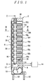
- FIG. 1 shows a flexible actuator 2 used as a robot finger of a robot according to a first embodiment.
- the flexible actuator 2 includes a long movable part 6 that is bent by a liquid moving toward a main liquid chamber 4, an actuator body 8 integral with a base of the movable part 6, a reservoir 10 that is built in the actuator body 8 and where a liquid moves to and from the main liquid chamber 4, a pump 12 that moves the liquid between the reservoir 10 and the main liquid chamber 4, and a pump driving unit 14 that controls the pump 12.
- the actuator body 8 is a root of the robot finger and secured to a hand of the unshown robot.
- the movable part 6 includes a long tube 16 that forms the main liquid chamber 4, a plurality of frame members 18a, 18b ... aligned at predetermined intervals along a length of the tube 16, and a core member 20 that holds the alignment of the frame members 18a, 18b ....
- the tube 16 is made of a flexible translucent elastic material of synthetic resin.
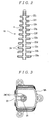
- FIG. 2 shows a section of the tube 16 in FIG. 1 in a direction perpendicular to the drawing sheet (II-II in FIG. 1). As apparent from FIG. 2, the tube 16 has a fernlike appearance in which a narrow hollow portion 24 communicates between flat expanded hollow portions 22a, 22b ... provided at predetermined intervals along the length.
- the plurality of frame members 18a, 18b ... are substantially rectangular hollow members on plane view made of synthetic resin.
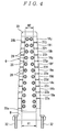
- a frame member 18h in FIG. 3 has a recess 26 provided on a side abutting the core member 20, into which the narrow hollow portion 24 of the tube 16 is inserted, and is vertically held between expanded hollow portions 22h, 22i ... of the tube 16.
- the frame members 18a, 18b ... other than the frame member 18h also have recesses 26, into which the narrow hollow portion 24 of the tube 16 is inserted, and are vertically held between the expanded hollow portions 22a, 22b ... of the tube 16.
- a cap 30 made of synthetic resin or the like is placed on a frame member 18j at the top.
- the expanded hollow portion 22a at a base has a largest transverse cross sectional area
- expanded hollow portions 22b, 22c ... toward a tip have gradually decreasing transverse cross sectional areas
- an expanded hollow portion 22j at the tip has a smallest transverse cross sectional area.
- the base of the movable part 6 where the expanded hollow portion 22a is positioned corresponds to a first bending portion of the invention
- the tip of the movable part 6 where the expanded hollow portion 22j is positioned corresponds to a second bending portion of the invention.
- the frame member 18a at a base has a largest transverse cross sectional area
- frame members 18b, 18c ... toward a tip have gradually decreasing transverse cross sectional areas
- a frame member 18j at the tip has a smallest transverse cross sectional area.
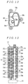
- the core member 20 is an elastic deformable plate member made of synthetic resin, vertically secures the frame members 18a, 18b ... with spaces therebetween using a plurality of screws 28, and is secured at its bottom to the actuator body 8.
- a tapered plate member is used as the core member 20 in which a base 20a has a large width H1, with widths decreasing toward a tip 20b, and the tip 20b has a smallest width H2.
- a sheet flexible material (not shown) is attached to the entire surface of the core member 20 with the screws 28.
- the transverse cross sectional area of the expanded hollow portion 22j at the tip is 30% to 80% of the transverse cross sectional area of the expanded hollow portion 22a at the base .
- the actuator body 8 is secured to the hand of the robot by securing screws 32.
- the pump 12 built in the actuator body 8 uses, for example, a piezo type diaphragm pump, and connects to a bottom opening of the tube 16 and the reservoir 10 that stores a predetermined amount of hydraulic fluid S such as liquid silicone.
- the pump 12 supplies the hydraulic fluid S in the reservoir 10 to the tube 16, or returns the hydraulic fluid S in the tube 16 to the reservoir 10 by controlling the pump driving unit 14.
- the actuator body 8 includes a light receiving and emitting unit 34 having a light emitting element such as a light emitting diode and a light receiving element such as a photodiode.
- a reflection unit 36 such as a mirror is provided on a lower surface of the frame member 18a at the bottom facing the light receiving and emitting unit 34 via the expanded hollow portion 22a of the tube 16.
- the light receiving and emitting unit 34 sends detected information on an amount of emitted light (an amount of received light) toward (from) the reflection unit 36 to the pump driving unit 14 as required.
- the pump driving unit 14 includes an input interface circuit for reading a detected signal from the light receiving and emitting unit 34, a processing unit that performs predetermined processing for controlling the pump 12 according to a predetermined program, a storage unit such as a RAM or a ROM, and an output interface circuit that outputs a voltage control signal to a piezo element or the like of the piezo type diaphragm pump obtained by the processing unit.
- the storage unit stores a storage table for estimating an amount of displacement of the movable part 6 from both values of a change in hydraulic pressure of the main liquid chamber 4 of the tube 16 and a change in the amount of received light input from the light receiving and emitting unit 34 .
- the processing unit performs the predetermined processing for controlling the pump 12 with reference to the storage table.
- a control current is output from the pump driving unit 14 to the pump 12.
- the pump 12 supplies the hydraulic fluid S in the reservoir 10 to the tube 16 (main liquid chamber 4)
- the hydraulic fluid S flows into the expanded hollow portions 22a, 22b ... of the tube 16 to increase their capacities.
- the expanded hollow portion 22a at the base has the largest transverse cross sectional area
- the expanded hollow portion 22j at the tip has the smallest transverse cross sectional area, with the transverse cross sectional areas gradually decreasing from the base toward the tip.
- the expanded hollow portion 22a at the base produces a larger force to bend the core member 20 (hereinafter referred to as a bending force) than any other expanded hollow portions.
- Other expanded hollow portions 22b, 22c ... 22j have the gradually decreasing transverse cross sectional areas, so that bending forces decrease toward the tip (toward the expanded hollow portion 22j), and the expanded hollow portion 22j at the tip produces a smallest bending force.
- a force to return to an upright condition gradually increases to cause resilience against bending displacement of the expanded hollow portions 22a, 22b ....
- the core member 20 of this embodiment is tapered such that the base 20a has the large width H1, with the widths decreasing toward the tip 20b, and the tip has the smallest width H2.
- the resilience gradually decreases with the increasing amount of bending displacement toward the expanded hollow portion 22j at the tip, thus the bending force and the resilience decreasing toward the tip are balanced, and the entire movable part 6 bends with a substantially even curvature under a no-load condition.
- the actuator can evenly grip the entire object without local bending.
- the cap 30 When the cap 30 corresponding to the tip of the robot finger pinches to turn a screw, the cap 30 has to produce a large force.
- a reaction force of this action is proportional to a distance from the cap 30, thus the bending force of the actuator is desirably larger at the base than the tip.
- the actuator of the invention produces a bending force higher than a certain level, the resilience has relatively less influence, and the difference in the transverse cross sectional areas of the expanded hollow portions 22a, 22b ... provides the bending force larger at the base than the tip. This allows stable pinching without increased curvature only at the tip.
- the transverse cross sectional area of the expanded hollow portion 22j at the tip is 30% or more of the transverse cross sectional area of the expanded hollow portion 22a at the base, thus in gripping a soft circular object, the movable part 6 does not locally bend but bends along the circular object with the same curvature to grip the object with an even force. Also, the transverse cross sectional area of the expanded hollow portion 22j at the tip is 80% or less of the transverse cross sectional area of the expanded hollow portion 22a at the base, thus in gripping an object, a large force by reaction of the gripping is not applied to the base to normally grip the object.
- An average transverse cross sectional area of the expanded hollow portions 22j, 22i, 22h ... at the tip that require no large bending force is small, thus a total amount of hydraulic fluid S required for bending decreases to allow quick bending.
- the flexible actuator 2 of this embodiment when the hydraulic fluid S flows into the tube 16 to increase the capacities of the expanded hollow portions 22a, 22b ..., the entire actuator bends with the substantially even curvature in gently gripping the soft object, thus allowing enclosing to grip the soft object.
- a bending force corresponding to moment from the tip is caused to prevent the finger tip only from being bending, thus ensuring operation and allowing use as the robot finger that acts like a human finger.
- the core member 20 having the large width at the base 20a prevents the bending force from concentrating on the base of the movable part 6.
- the entire movable part 6 bends with the even curvature to act like the human finger.
- the pump 12 that moves the liquid between the main liquid chamber 4 (in the tube 16) and the reservoir 10 is built in the actuator body 8 integral with the base of the movable part 6, the actuator body 8 includes the light receiving and emitting unit 34, the reflection unit 36 is provided on the frame member 18a at the bottom facing the light receiving and emitting unit 34 via the expanded hollow portion 22a of the tube 16.
- a driving unit the pump 12
- a sensor unit the light receiving and emitting unit 34 and the reflection unit 36
- the pump 12 is activated to increase or decrease the capacities of the expanded hollow portions 22a, 22b ... of the tube 16 to vertically move the frame members 18a, 18b ..., and to bend the core member 20 with the widths gradually decreasing toward the tip 20b to cause the bending displacement of the movable part 6.
- the movable part 6 serves as the robot finger that securely grips the object along the object.
- FIGS. 6 to 8 show a flexible actuator 40 according to a second embodiment of the invention.
- Like components as in the first embodiment shown in FIGS. 1 to 5 are denoted by like reference numerals, and descriptions thereof will be omitted.
- the flexible actuator 40 is used as an actuator for massaging a shoulder, and includes a movable part 42, an actuator body 8 integral with a base of the movable part 42, and a pump driving unit 14.
- a reservoir 10 and a pump 12 are built in the actuator body 8.
- the movable part 42 includes a long tube 44 that forms a main liquid chamber, a plurality of frame members 46a, 46b ... aligned at predetermined intervals along a length of the tube 44, and a core member 48 that holds the alignment of the frame members 46a, 46b ....
- the tube 44 is made of a flexible translucent elastic material of synthetic resin, has a fernlike appearance in which a narrow hollow portion (not shown) communicates between flat expanded hollow portions 50a, 50b ... provided at predetermined intervals along the length, and has a shape like the tube 16 in the first embodiment.
- the plurality of frame members 46a, 46b ... are substantially rectangular hollow members on plane view made of synthetic resin, and have shapes like the frame members 18a, 18b ... in the first embodiment.
- an expanded hollow portion 50g at a center along the length has a largest transverse cross sectional area, with transverse cross sectional areas gradually decreasing from the expanded hollow portion 50g toward a tip and a base, and an expanded hollow portion 50n at the tip and the expanded hollow portion 50a at the base have a smallest transverse cross sectional area.
- the center along the length of the movable part 42 where the expanded hollow portion 50g is positioned corresponds to a first bending portion of the invention, and the base and the tip of the movable part 42 where the expanded hollow portions 50n, 50a are positioned correspond to second bending portions of the invention.
- frame members 46f, 46g at a center along the length have a largest transverse cross sectional area, with sectional areas gradually decreasing from the frame members 46f, 46g toward a tip and a bottom, and a frame member 46n at the tip and a frame member 46a at the base have a smallest transverse cross sectional area.
- the core member 48 is an elastic deformable plate member made of synthetic resin, vertically secures the plurality of frame members 46a, 46b ... with spaces therebetween using a plurality of screws 28, and is secured at its bottom to the actuator body 8.
- the core member 48 is shaped such that a center along the length has a large width H3, with widths gradually decreasing toward a tip 48a and a base 48b, and the tip 48a and the base 48b have a smallest width H4.
- the transverse cross sectional areas of the expanded hollow portion 50n at the tip and the expanded hollow portion 50a at the base are 60% of the transverse cross sectional area of the expanded hollow portion 50g at the center.
- the actuator body 8 is secured to a grip 52 by securing screws 32.
- the expanded hollow portion 50g at the center along the length has the largest transverse cross sectional area, with the sectional areas gradually decreasing from the expanded hollow portion 50g toward the tip and the base, and the expanded hollow portion 50n at the tip and the expanded hollow portion 50a at the base have the smallest transverse cross sectional area.
- the expanded hollow portions 50e, 50f, 50g, 50h (denoted by 50CT in FIG. 7) at the center along the length produce a larger bending force than any other expanded hollow portions.
- the flexible actuator 40 as the actuator for massaging a shoulder is applied to a human shoulder as shown in FIG. 8 to repeat bending the movable part 42, thus increasing the bending force of the expanded hollow portion 50CT at the center along the length to ensure massaging the shoulder.
- the pump 12 is activated to increase or decrease the capacities of the expanded hollow portions 50a, 50b ... to vertically move the frame members 46a, 46b ..., and to bend the core member 48 with the width gradually decreasing toward the ends to cause bending displacement of the movable part 42.
- the actuator for massaging a shoulder can be provided in which even when the flexible actuator 40 pinches an object with its both ends, bending does not concentrate on the both ends.
- FIG. 9 shows a flexible actuator 2 used as a robot finger of a robot according to a third embodiment.
- FIG. 10 is a plane view of FIG. 9
- FIG. 11 is a view taken along line XI-XI in FIG. 9 as seen in the direction of the arrow
- FIG. 12 is a view taken along line XII-XII in FIG. 9 as seen in the direction of the arrow.
- the flexible actuator 2 includes a long movable part 6 that is bent by a liquid moving toward a main liquid chamber 4, an actuator body 8 integral with a base of the movable part 6, a reservoir 10 where a liquid moves to and from the main liquid chamber 4, a pump 12 that moves the liquid between the reservoir 10 and the main liquid chamber 4, and a pump driving unit 14 that controls the pump 12.
- the actuator body 8 is a root of the robot finger and secured to a hand of the unshown robot.
- the movable part 6 includes a long first tube 16 that forms the main liquid chamber 4, a long second tube 17 that is placed along the first tube 16 and forms the reservoir 10, a plurality of frame members 18a, 18b ... aligned at regular intervals along lengths of the first tube 16 and the second tube 17, and a core member 20 that holds the alignment of the frame members 18a, 18b ....
- the first tube 16 that forms the main liquid chamber 4 is made of an expandable and shrinkable elastic material of synthetic resin.
- FIG. 13 shows shapes of the first tube 16 and the second tube 17 seen from a side of the core member 20, and the first tube 16 has a fernlike appearance in which a narrow hollow portion 24 communicates between flat expanded hollow portions 22a, 22b...provided at predetermined intervals along the length.
- the second tube 17 that forms the reservoir 10 is made of an expandable and shrinkable elastic material of synthetic resin thinner than that of the first tube 16, and has a fernlike appearance in which a narrow hollow portion 25 communicates between flat expanded hollow portions 23a, 23b ... provided at predetermined intervals along the length.
- the expanded hollow portions 23a, 23b ... of the second tube 17 are placed to longitudinally overlap the expanded hollow portions 22a, 22b of the first tube 16.
- the plurality of frame members 18a, 18b are substantially rectangular on plane view and have cavities therein, and each of the frame members 18a, 18b ... has an air hole 19 that communicates between the cavity and an outside.
- a frame member 18g in FIG. 12 has two recesses 26a, 26b provided on a side abutting the core member 20, with the narrow hollow portion 24 of the first tube 16 being inserted into one recess 26a, and is vertically held between expanded hollow portions 22g, 22h ... of the first tube 16.
- the frame members other than the frame member 18g also have a recess 26a, with the narrow hollow portion 24 of the first tube 16 being inserted into the recess 26a, and is vertically held between the expanded hollow portions of the first tube 16.
- the narrow hollow portion 25 of the second tube 17 is inserted into another recess 26b provided on the frame member 18g in FIG. 12, and an expanded hollow portion 23g of the second tube 17 that expands near the narrow hollow portion 25 is placed in the cavity of the frame member 18g.
- the expanded hollow portions of the second tube 17 other than the expanded hollow portion 23g are also placed in the cavities of other frame members.
- a cap 30 is placed also as shown in FIG. 1.
- the actuator body 8 is secured to the hand of the robot by securing screws 32.
- the pump 12 built in the actuator body 8 uses, for example, a piezo type diaphragm pump, and connects to a bottom opening of the first tube 16 that forms the main liquid chamber 4 and a bottom end of the second tube 17 that forms the reservoir 10 storing a predetermined amount of hydraulic fluids such as liquid silicone.
- the pump 12 supplies the hydraulic fluid S in the reservoir 10 to the main liquid chamber 4, or returns the hydraulic fluid S in the main liquid chamber 4 to the reservoir 10 by controlling the pump driving unit 14.
- the actuator body 8 includes a light receiving and emitting unit 34 having a light emitting element such as a light emitting diode and a light receiving element such as a photodiode.
- a reflection unit 36 such as a mirror is provided on a lower surface of the frame member 18a at the bottom facing the light receiving and emitting unit 34 via the expanded hollow portion 22a of the first tube 16.
- the light receiving and emitting unit 34 sends detected information on an amount of emitted light (an amount of received light) toward (from) the reflection unit 36 to the pump driving unit 14 as required.
- the pump driving unit 14 includes an input interface circuit for reading a detected signal from the light receiving and emitting unit 34, a processing unit that performs predetermined processing for controlling the pump 12 according to a predetermined program, a storage unit such as a RAM or a ROM, and an output interface circuit that outputs a voltage control signal to a piezo element of the piezo type diaphragm pump obtained by the processing unit.
- the storage unit stores an amount of displacement of the movable part 6 corresponding to a relationship between hydraulic pressure of the main liquid chamber 4 and the amount of received light input from the light receiving and emitting unit 34 as a storage table.
- the processing unit performs the predetermined processing for controlling the pump 12 with reference to the storage table.
- a control current is output from the pump driving unit 14 to the pump 12.
- the pump 12 supplies the hydraulic fluid S in the reservoir 10 to the main liquid chamber 4, the hydraulic fluid S flows into the expanded hollow portions 22a, 22b ... of the first tube 16 to increase their capacities.
- the expanded hollow portions 23a, 23b ... of the second tube 17 a placed in the cavities of the frame members 18a, 18b ..., respectively are shrunk.
- the pump 12 returns the hydraulic fluid S in the main liquid chamber 4 to the reservoir 10, the capacities of the expanded hollow portions 22a, 22b ... of the first tube 16 decrease to return the frame members 18a, 18b ... to their original positions by resilience of the core member 20. This brings the movable part 6 into an upright condition as shown in FIG. 11.
- each of the frame members 18a, 18b ... has the airhole 19 that communicates between the cavity and the outside to prevent air compression in the cavity, thus allowing expansion of the expanded hollow portions 23a, 23b of the second tube 17.
- the expanded hollow portions 22a, 22b of the first tube 16 and the expanded hollow portions 23a, 23b ... of the second tube 17 are placed to longitudinally overlap each other, and the pump 12 is built in the actuator body 8 integral with the base of the movable part 6, thus providing a small actuator.
- the first tube 16 that forms the main liquid chamber 4 and the second tube 17 that forms the reservoir 10 are placed along each other in the movable part 6. Even if a position of the movable part 6 changes, either the main liquid chamber 4 or the reservoir 10 is not positioned above or below the other. Further, the main liquid chamber 4 and the reservoir 10 are placed close to each other, so that the amounts of hydraulic fluid S supplied and discharged to and from the main liquid chamber 4 by gravity do not change. Therefore, the change in the position of the movable part 6 causes no change in an amount of bending displacement of the pump driving unit 14.
- the second tube 17 that forms the reservoir 10 includes the flat expanded hollow portions 23a, 23b provided at the predetermined intervals along the length, and the narrow hollow portion 25 communicates between the expanded hollow portions . This allows the second tube 17 per se to serve as a plurality of reservoirs connected by a tube, thus providing a simple and inexpensive actuator.
- the second tube 17 is made of the thin elastic material, thus allowing spaces in the cavities of the frame members 18a, 18b ... to be effectively used as the expanded hollow portions 23a, 23b to provide a small actuator.
- FIG. 15 is a sectional view of a flexible actuator 2 used as a robot finger of a robot according to a fourth embodiment
- FIG. 16 is a back view of the flexible actuator 2
- FIG. 17 is a side view of the flexible actuator 2.
- the flexible actuator 2 includes a first actuator AC1 and a second actuator AC2 joined to a base of the first actuator AC1.
- the first actuator AC1 includes a tube 82 that forms a liquid chamber, a plurality of frame members 84a, 84b ... and a tip frame member 86 provided at predetermined intervals along a length of the tube 82, and a connection member 88 that holds the adjacent frame members 84a, 84b ... and the tip frame member 86 so as to swing against each other.
- the tube 82 is made of a flexible elasticmaterial of synthetic resin, and includes flat expanded hollow portions 92a, 92b ... provided at predetermined intervals along the length, and a connection tube 94 that communicates between the expanded hollow portions 92a, 92b ..., and the connection tube 94 is provided at edges of the expanded hollow portions 92a, 92b ....
- the plurality of frame members 84a, 84b ... and the tip frame member 86 are substantially rectangular members on plane view made of synthetic resin, and an upper surface of the frame member 84a at the base, upper and lower surfaces of the frame members 84b, 84c ..., and an upper surface of the tip frame member 86 are flat.
- the upper surface of the frame member 84a, the upper and lower surfaces of the frame members 84b, 84c ..., and a lower surface of the tip frame member 86 are held with the flat portions in surface contact with the expanded hollow portions 92a, 92b ... of the tube 82.
- connection tube 94 of the tube 82 extends along the length apart from the expanded hollow portions 92a, 92b ... and the frame members 84a, 84b ... placed in surface contact with each other, and is held between two connection members 88.
- connection members 88 are elastic deformable plate members made of synthetic resin, and vertically secure the frame members 84a, 84b ... and the tip frame member 86 with spaces therebetween using a plurality of screws 96.
- Each connection member 88 has thin portions between the frame members to form hinges 54a, 54b ... for holding the frame members so as to swing against each other.
- guide grooves (guide portions) 56a, 56b ..., 90a are formed on surfaces facing the hinges 54a, 54b of the frame members 84a, 84b and the tip frame member 86, and the guide grooves 56a, 56b ..., 90a accommodate a spring member 58.
- Both ends of the spring member 58 are secured to the frame member 84a and the tip frame member 86 by screws 60 to produce a spring force in a compressing direction of the expanded hollow portions 92a, 92b ... of the tube 82.
- the second actuator AC2 includes a connection member 66 that secures the frame member 84a at the base and a base frame member (an actuator mounting portion) 62 by screws 64 with a predetermine space therebetween, an expanded hollow portion 70 of the tube 68 held between the flat lower surface of the frame member 84a at the base and the upper surface of the base frame member 62, and a spring member 72 that is secured at its both ends to the frame member 84a at the base and the base frame member 62 by unshown screws and produces a spring force in a compressing direction of the expanded hollow portion 70 of the tube 68.
- the expanded hollow portion 70 is set to expand toward a side without the connection member 88 and the spring member 58 of the first actuator AC1.
- a central portion of the connection member 66 that secures the frame member 84a at the base and the base frame member 62 has a thin portion to form a hinge 66a for holding both frame members so as to swing against each other like the connection member 88.
- An unshown fluid supply control unit connects to bottom openings of the tube 82 that forms the first actuator AC1 and the tube 68 that forms the second actuator AC2, and the fluid supply control unit supplies and returns the fluid to and from the liquid chamber in the tubes 82,68.
- the expanded hollow portions 92a, 92b of the tube 82 increases their capacities by the fluid flowing therein.
- the expanded hollow portions 92a, 92b ... with the increased capacities, that is, expanded by the fluid flowing therein bend the hinges 54a, 54b ... of the connection member 88 to displace the frame members 84b, 84c ... and the tip frame member 86.
- the expanded hollow portions 92a, 92b ... are held between the frame members 84a, 84b ... and the tip frame member 86 with large contact areas, so that the expanded hollow portions 92a, 92b expand such that a force to bend the hinges 54a, 54b ... increases to deeply bend the first actuator AC1 as shown in FIG. 18.
- the spring member 58 When the fluid supply control unit returns the fluid from the tube 82, the spring member 58 produces the spring force in the compressing direction of the expanded hollow portions 92a, 92b ..., thus resilience of the spring member 58 brings the first actuator AC1 into its original upright condition.
- the expanded hollow portion 70 of the tube 68 increases its capacity by the fluid flowing therein.
- the expanded hollow portion 70 with the increased capacity that is, expanded by the fluid flowing into the tube 68 bends the hinge 66a of the connection member 66 to displace the frame member 84a from a direction different from the bending direction of the first actuator AC1, and slant the entire first actuator AC1.
- the spring member 72 When the fluid supply control unit returns the fluid from the tube 68, the spring member 72 produces the spring force in the compressing direction of the expanded hollow portion 70, thus resilience of the spring member 72 returns the slanted entire first actuator AC1 to its original condition.
- the flexible actuator 2 can freely adjust the resilience simplyby selecting the spring member 58 of the first actuator AC1, thus repulsion of the spring member does not limit bending.
- the spring member 58 of the first actuator AC1 is secured only at the both ends, and the spring member 58 absorbs any partially deep bending condition of a hinge in its entire extension to prevent partially excessive extension, thus increasing durability.
- the guide grooves 56a, 56b ..., 90a of the frame members 84a, 84b ... and the tip frame member 86 accommodate the spring member 58, thus preventing the position of the spring member 58 from being shifted in bending the first actuator AC1.
- the first actuator AC1 bends deeply like a human finger to ensure enclosing to grip a soft object such as a fruit or a paper cup. Further, the first actuator AC1 that bends in a predetermined direction, and the second actuator AC2 that slants the entire first actuator AC1 in the direction different from the bending direction of the first actuator AC1 are provided, thus allowing the position of the tip frame member 86 corresponding to the finger tip of the robot to be changed to precisely grip a small object.
- FIGS. 20 and 21 a flexible actuator according to a fifth embodiment of this embodiment will be described with reference to FIGS. 20 and 21.
- Like components as in the fourth embodiment are denoted by like reference numerals, and descriptions thereof will be omitted.
- the flexible actuator 2 of this embodiment includes a tube 82 that forms a liquid chamber, a plurality of frame members 74a, 74b ... and a tip frame member 76 aligned at predetermined intervals along a length of the tube 82, and connections 78a, 78b ... that hold the adjacent frame members 74a, 74b ... and the tip frame member 76 so as to swing against each other.
- the frame members 74a, 74b ... and the tip frame member 76, and the connections 78a, 78b ... are integrally molded of a bending-resistant resin material such as polypropylene, and the connections 78a, 78b are thin to form hinges.
- a surface facing a spring member 58 of each of the connections 78a, 78b ... has slots 80.
- expanded hollow portions 92a, 92b ... of the tube 82 are simply passed through the slots 80 of the connection 78a, 78b ... to be placed on sides of the frame members 74a, 74b.
- the expanded hollow portions 92a, 92b of the tube 82 are flexible and thin, thus can be easily deformed to be passed through the elongate slots 80 as shown. Operations of this embodiment are similar to those of the fourth embodiment.
- This embodiment achieves similar advantages as those of the first actuator AC1 in the fourth embodiment, and the frame members 74a, 74b ... and the tip frame member 76, and the connections 78a, 78b ... are integrally molded of the resin material, thus providing a flexible actuator that includes a small number of components, has a reduced weight, and is easy to assemble.
- the frame members 84a, 84b ..., 74a, 74b ..., and the tip frame members 86, 76 have the guide grooves 56a, 56b..., 90a.
- the frame members 84a, 84b ... and the tip frame members 86, 76 may have guide holes communicating with each other instead of the guide grooves, and the holes may accommodate the spring member 58.
- the flexible actuators according to the first to fifth embodiments can be used as an actuator for a pet robot that finely acts like an animal.
- the actuator is compact even when used as the pet robot, thus providing the pet robot that finely acts like an animal.
- An actuator that operates as a robot finger of a robot must bend like a human finger, and enclose to grip a soft object such as a fruit or a paper cup, pinch a small object such as a screw with its tip, or bend to push a switch with its tip.
- a substantially even bending force is desirably produced throughout the finger, but in pinching the object with the tip, a bending force proportional to a distance from the tip is desirably produced in terms of moment.
- the actuator entirely bends with a predetermined curvature to grip the object, and do not have a structure in which an appropriate bending force is produced at each part.
- it is difficult to configure an actuator capable of performing various operations such as enclosing to grip the soft object, pinching the small object, or pushing the switch with the tip, with appropriate gripping forces like the human finger.
- the expanded hollow portion placed in the first bending portion of the movable part has the large transverse cross sectional area
- the expanded hollow portion placed in the second bending portion has the small transverse cross sectional area, so that the first bending portion produces the large bending force and the second bending portion produces the small bending force simply by the fluid flowing into the tube to increase the capacities of the expanded hollow portions.
- the flexible actuator in which the main liquid chamber with the movable part that is bent by the liquid flowing therein, and the reservoir where the liquid moves to and from the main liquid chamber are placed along the length, even if the position of the movable part changes, the amount of fluid supplied from the reservoir to the main liquid chamber, and the amount of fluid discharged from the main liquid chamber to the reservoir by gravity do not change. Therefore, the change in the position of the movable part causes no change in the amount of bending deformation.
Landscapes
- Engineering & Computer Science (AREA)
- Mechanical Engineering (AREA)
- Robotics (AREA)
- Chemical & Material Sciences (AREA)
- Analytical Chemistry (AREA)
- Physics & Mathematics (AREA)
- Fluid Mechanics (AREA)
- General Engineering & Computer Science (AREA)
- Manipulator (AREA)
- Actuator (AREA)
- Reciprocating Pumps (AREA)
Abstract
Description
- The present invention relates to a flexible actuator that can be used for driving a robot capable of gripping, pinching, or pushing and a pet robot that acts like an animal.
- As described in Japanese Patent Laid-Open No. 5-172118 and Japanese Patent Laid-Open No. 5-164112, known actuators for gripping an object include a cylindrical elastic body having a plurality of pressure chambers therein and adjust a fluid pressure applied to each pressure chamber to curve and deform the cylindrical elastic body (hereinafter referred to as the first prior art).
- Further, as described in Japanese Patent Laid-Open No. 2-17204, an actuator different from the first prior art is also known in which a driving source and a pump are integrated into a hydraulic cylinder (hereinafter referred to as the second prior art).
- An actuator that operates as a robot finger of a robot must bend like a human finger, and enclose to grip a soft object such as a fruit or a paper cup, pinch a small object such as a screw with its tip, or bend to push a switch with its tip. In gripping the paper cup with the entire robot finger, a substantially even bending force is desirably produced throughout the finger. On the other hand, in pinching the object with the tip, a bending force proportional to a distance from the tip is desirably produced in terms of moment. Reducing the bending force at the tip saves power for bending.
- However, in the first prior art, the actuator entirely bends with a predetermined curvature to grip the object, and do not have a structure in which an appropriate bending force is produced at each part. Thus, it is difficult to configure an actuator capable of performing various operations such as enclosing to grip the soft object, pinching the small object, or pushing the switch with the tip, with appropriate gripping forces like the human finger.
- The second prior art is of the piston type, and requires many actuators and associated sensors or mechanisms to configure a flexible actuator, so that it is difficult to cause the actuator to operate as a robot finger.
- Even if the actuators according to the first prior art and the second prior art are to be manufactured as pet robots that finely act like animals, many sensors and complex mechanisms must be provided to cause complex appearances.
- Further, in the first prior art and the second prior art, an operating fluid must be supplied to the pressure chamber, or a pump that discharges the operating fluid from the pressure chamber must be placed outside via a fluid tube (referred to as an operating tube in the specification of the prior art) which cannot provide a small actuator. Thus, it is difficult to use the actuator as the pet robot that finely acts like an animal.
- When a liquid is used as the operating fluid of the first prior art and the second prior art, a reservoir that stores the liquid is placed outside together with the pump. Between when the reservoir is above the pressure chamber (hereinafter referred to as a main liquid chamber) and when the reservoir is below the main liquid chamber, amounts of liquid supplied and discharged to and from the main liquid chamber by gravity change depending on changes in positions of the cylindrical elastic body. Thus, each change in the position of the cylindrical elastic body tends to cause a change in an amount of bending deformation.
- The present invention has been achieved to solve the above described problems in the prior art, andhas an object to provide a flexible actuator capable of gripping a soft object like a human finger and finely acting like an animal, and also avoiding a change in an amount of liquid moving between a reservoir and a main liquid chamber by gravity even if a liquid is used as an operating fluid, and keeping a constant amount of bending deformation even if the actuator changes its position.
- To solve the problems, a flexible actuator according to the invention has the following configuration. Specifically, the flexible actuator according to the invention includes: a long movable part that is bent by a liquid moving toward a main liquid chamber; a reservoir where the liquid moves to and from the main liquid chamber; a pump that moves the liquid between the reservoir and the main liquid chamber; and a pump driving unit that controls the pump, wherein the movable part includes a long tube that forms the main liquid chamber, a plurality of frame members aligned at predetermined intervals along a length of the tube, and a resilient core member that holds the alignment of the frame members, the tube is made of a flexible elastic material, and includes a plurality of flat expanded hollow portions provided at predetermined intervals along the length and a narrow hollow portion that communicates between the expanded hollow portions, the plurality of frame members are formed by flat members and longitudinally hold the plurality of expanded hollow portions by the narrow hollow portion of the tube inserted into recesses or holes provided on sides abutting the coremember, the movable part has a first bending portion that produces a large bending force and a second bending portion that produces a small bending force, the expanded hollow portion placed in the first bending portion has a large transverse cross sectional area, and the expanded hollow portion placed in the second bending portion has a small transverse cross sectional area.
- According to the invention, the expanded hollow portion placed in the first bending portion has the large transverse cross sectional area, and the expanded hollow portion placed in the second bending portion has the small transverse cross sectional area, so that the first bending portion produces the large bending force and the second bending portion produces the small bending force simply by a fluid flowing into the tube to increase capacities of the expanded hollow portions, thus allowing operations different from those of a conventional actuator.
- The flexible actuator may be used as a robot finger or the like, and the expanded hollow portion at a base of the movable part as the first bending portion may have a largest transverse cross sectional area, with transverse cross sectional areas of the expanded hollow portions gradually decreasing toward a tip of the movable part, and the expanded hollow portion at the tip of the movable part as the second bending portion may have a smallest transverse cross sectional area.
- When the flexible actuator with such a configuration is used as the robot finger, the base of the movable part that is a root of the robot finger produces a large bending force, and the tip of the movable part that is a tip of the robot finger produces a small bending force to bend. This allows the actuator to reliably enclose to grip a soft object, pinch a small object, or push a switch with the tip, and act like a human finger.
- The transverse cross sectional area of the expanded hollow portion placed in the second bending portion may be 30% to 80% of the transverse cross sectional area of the expanded hollow portion placed in the first bending portion.
- In this way, providing the second bending portion at the base prevents a large force to fold the base from being applied in gripping the object, thus allowing the object to be properly gripped. Further, an average sectional area at the tip that requires no large bending force is small, thus a total amount of hydraulic fluid required for bending decreases to allow quick bending and extension.
- The core member may be a member having gradually decreasing resilience from the base toward the tip of the movable part. Alternatively, the core member may be a tapered plate material in which a base has a large width, with widths gradually decreasing toward a tip, and the tip has a smallest width.
- This exerts no influence on bending displacement of the movable part. When the movable part bends under a no-load or light-load condition, the core member having the large width at the base prevents the bending force from concentrating on the base of the movable part, thus allowing the entire movable part to bend with an even curvature.
- The flexible actuator may be used as an actuator for massaging a shoulder, and the expanded hollow portion at a center along the length of the movable part as the first bending portion has a largest transverse cross sectional area, with transverse cross sectional areas of the expanded hollow portions gradually decreasing toward both ends along the length of the movable part, and the expanded hollow portions at the both ends of the movable part as the second bending portion have a smallest transverse cross sectional area.
- When the flexible actuator with such a configuration is used as the actuator for massaging a shoulder by being applied to a human shoulder, a bending force of the expanded hollow portion at the center along the length increases to ensure massaging the shoulder.
- The transverse cross sectional area of the expanded hollow portion placed in the second bending portion may be approximately 60% of the transverse cross sectional area of the expanded hollow portion placed in the first bending portion.
- In this way, the bending force of the first bending portion that requires a large bending force in operation such as pinching increases and concentrates since the second bending portion requires a small bending force and a reduced amount of hydraulic fluid, thus providing quick shoulder massage.
- The core member may be a member having gradually decreasing resilience from the center along the length toward the both ends of the movable part. Alternatively, the core member may be a plate material in which a center along a length has a large width, with widths gradually decreasing toward both ends, and the both ends have a smallest width.
- In this way, the core member has low resilience at a portion where the moving part produces a small bending force. Thus, there can be provided an actuator for massaging a shoulder capable of enclosing the entire shoulder for massaging with a constant curvature in massaging with a small force.
- There may be provided a flexible actuator including: a long movable part that is bent by a liquid moving toward a main liquid chamber; a reservoir where the liquid moves to and from the main liquid chamber; a pump that moves the liquid between the reservoir and the main liquid chamber; and a pump driving unit that controls the pump, wherein the movable part includes the main liquid chamber and the reservoir placed along a length, a plurality of frame members aligned at predetermined intervals along lengths of the main liquid chamber and the reservoir, and a resilient core member that holds the alignment of the frame members. The main liquid chamber and the reservoir are placed along a length in the movable part, so that even if a position of the movable part changes, an amount of fluid supplied from the reservoir to the main liquid chamber, and an amount of fluid discharged from the main liquid chamber to the reservoir by gravity do not change. Therefore, the change in the position of the movable part causes no change in an amount of bending deformation of the pump driving unit. The main liquid chamber and the reservoir are placed along the length to provide a small actuator.
- The reservoir may be formed by a tube made of an expandable and shrinkable elastic material, and includes a plurality of flat expanded hollow portions provided at predetermined intervals along the length, and a narrow hollow portion that communicates between the expanded hollow portions.
- This allows a plurality of reservoirs to be connected by a tube to configure one reservoir with a large capacity and a simple structure, thus providing an inexpensive actuator.
- The main liquid chamber may be formed by a tube made of an expandable and shrinkable elastic material, and includes a plurality of flat expanded hollow portions provided at predetermined intervals along the length, and a narrow hollow portion that communicates between the expanded hollow portions, and each expanded hollow portion of the main liquid chamber may be placed to longitudinally overlap each expanded hollow portion of the reservoir. This provides a smaller actuator.
- The plurality of frame members may be hollow members with cavities therein, and the expanded hollow portions of the reservoir may be placed in the cavities of the plurality of frame members.
- This provides a small actuator with a short length. Each expanded hollow portion of the reservoir is placed in each cavity of the frame members, thus the fluid stored in the expanded hollow portions of the reservoir is not influenced by pressure due to bending of the movable part.
- The tube that forms the reservoir may be made of a flexible elastic material such that each expanded hollow portion of the tube can expand into the entire cavity.
- This allows a space in the cavity of the frame member to be effectively used as the reservoir, thus providing a small actuator.
- The plurality of frame members may include air holes that communicate between the cavities and an outside.
- This allows the air in the cavity to pass through the air hole to the outside when the expanded hollow portion of the tube that forms the reservoir expands into the cavity of the frame member. Thus, the air in the cavity exerts no influence on expansion of the expanded hollow portion of the tube that forms the reservoir.
- The pump may be built in an actuator body integral with an end of the movable part. In this case, the pump is built in the actuator body to be compact, thus the actuator can be used as a pet robot with a simple appearance.
- A sensor that detects the amount of moving fluid may be placed in any of the pump, the main liquid chamber, or the reservoir, and the pump driving unit may control the pump based on information from the sensor.
- This allows control of the movable part with high accuracy, and for example, causes fine acting like an animal when the actuator is used as the pet robot.
- There may be provided a flexible actuator including: a plurality of flat expanded hollow portions made of a flexible elastic material and provided at predetermined intervals along a length; a long tube in which a liquid chamber is formed by a connection tube that communicates between the plurality of expanded hollow portions and extends along the length; a plurality of flat frame members that longitudinally hold the plurality of expanded hollow portions of the tube with surface contact; and a connection that holds the adj acent frame members so as to swing against each other, wherein the actuator further includes at least one spring member for recovering rotating angle between the frame members, and the spring member is placed to produce a spring force in a compressing direction of the expanded hollow portions of the tube by the adjacent frame members.
- In this case, the actuator includes at least one spring member for recovering the rotating angle between the frame members, so that the spring member produces the spring force in the compressing direction of the plurality of expanded hollow portions to return the fluid from the tube, thus recovering to an upright condition. Further, the spring member is independent, thus facilitating adjusting the resilience to minimize repulsion in large bending due to the resilience.
- There may be provided a flexible actuator including: a first actuator that bends in a predetermined direction; and a second actuator joined to abase of the first actuator, wherein the first actuator includes: a plurality of flat expanded hollow portions made of a flexible elastic material and provided at predetermined intervals along a length; a long tube in which a liquid chamber is formed by a connection tube that communicates between the plurality of expanded hollow portions and extends along the length; a plurality of flat frame members that longitudinally hold the plurality of expanded hollow portions of the tube with surface contact; and a connection that holds the adjacent frame members so as to swing against each other, and the second actuator is placed between the frame member at the base of the first actuator and an actuator mounting portion, and the entire first actuator is slanted in a direction different from a bending direction of the first actuator.
- In this way, the first actuator that bends in a predetermined direction, and the second actuator that slants the entire first actuator in the direction different from the bending direction of the first actuator are provided, thus allowing a position of a tip frame member corresponding to the finger tip to be changed when the actuator is used as a robot finger of a robot to precisely grip a small object.
- The first actuator may include at least one spring member for recovering rotating angle between the frame members, and the spring member may be placed to produce a spring force in a compressing direction of the expanded hollow portions of the tube by the adjacent frame members. In this case, the spring member produces the spring force in the compressing direction of the plurality of expanded hollow portion to return the fluid from the tube, thus recovering to the upright position. Further, the spring member of the first actuator is independent, thus facilitating adjusting the resilience to minimize repulsion in large bending due to the resilience.
- Further, ends of the spring member may be secured to both ends of the aligned frame members. Thus, even in a local and deep bending condition, the spring member does not locally and excessively extend to increase durability.
- Each of the frame members may include a guide that guides extension and shrinkage of the spring member. This prevents the spring member from being shifted in bending the flexible actuator.
- The frame members and the connection may be integrally molded of resin. This provides a flexible actuator that includes a small number of components, has a reduced weight, and is easy to assemble.
-
- FIG. 1 is a vertical sectional view of a flexible actuator used as a robot finger according to a first embodiment of the invention;
- FIG. 2 is a view taken along line II-II in FIG. 1 as seen in the direction of the arrow, and shows a tube that is a component of the first embodiment;
- FIG. 3 is a view taken along line III-III in FIG. 1 as seen in the direction of the arrow;
- FIG. 4 shows the flexible actuator according to the first embodiment seen from a core member side;
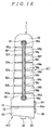
- FIG. 5 shows the flexible actuator according to the first embodiment being bent;
- FIG. 6 shows a flexible actuator used as an actuator for massaging a shoulder according to a second embodiment seen from a core member side;
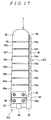
- FIG. 7 shows the flexible actuator according to the second embodiment being bent;
- FIG. 8 shows the flexible actuator according to the second embodiment being applied to a human shoulder for massaging;
- FIG. 9 shows a flexible actuator used as a robot finger according to a third embodiment of the invention seen from a core member side;
- FIG. 10 is a plane view of the flexible actuator according to the third embodiment;
- FIG. 11 is a view taken along line XI-XI in FIG. 9 as seen in the direction of the arrow;
- FIG. 12 is a view taken along line XII-XII in FIG. 9 as seen in the direction of the arrow;
- FIG. 13 shows a first tube and a second tube that configure the flexible actuator according to the third embodiment;
- FIG. 14 shows the flexible actuator according to the third embodiment being bent;
- FIG. 15 is a sectional view of a flexible actuator used as a robot finger according to a fourth embodiment of the invention;
- FIG. 16 is a back view of the flexible actuator according to the fourth embodiment;
- FIG. 17 is a side view of the flexible actuator according to the fourth embodiment;
- FIG. 18 shows the flexible actuator according to the fourth embodiment being bent;
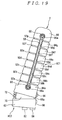
- FIG. 19 is a back view of the flexible actuator according to the fourth embodiment with a direction thereof changed;
- FIG. 20 is a side view of a flexible actuator used as a robot finger according to a fifth embodiment of the invention; and
- FIG. 21 shows frame members and a connection member that configure the flexible actuator according to the fifth embodiment being integrally molded.
-
- Embodiments of a flexible actuator according to the invention will be described below with reference to the accompanying drawings.
- FIG. 1 shows a
flexible actuator 2 used as a robot finger of a robot according to a first embodiment. - The
flexible actuator 2 includes a longmovable part 6 that is bent by a liquid moving toward a mainliquid chamber 4, anactuator body 8 integral with a base of themovable part 6, areservoir 10 that is built in theactuator body 8 and where a liquid moves to and from the mainliquid chamber 4, apump 12 that moves the liquid between thereservoir 10 and the mainliquid chamber 4, and apump driving unit 14 that controls thepump 12. Theactuator body 8 is a root of the robot finger and secured to a hand of the unshown robot. - The
movable part 6 includes along tube 16 that forms the mainliquid chamber 4, a plurality offrame members tube 16, and acore member 20 that holds the alignment of theframe members - The
tube 16 is made of a flexible translucent elastic material of synthetic resin. FIG. 2 shows a section of thetube 16 in FIG. 1 in a direction perpendicular to the drawing sheet (II-II in FIG. 1). As apparent from FIG. 2, thetube 16 has a fernlike appearance in which a narrowhollow portion 24 communicates between flat expandedhollow portions - The plurality of
frame members frame member 18h in FIG. 3 has arecess 26 provided on a side abutting thecore member 20, into which the narrowhollow portion 24 of thetube 16 is inserted, and is vertically held between expandedhollow portions tube 16. Theframe members frame member 18h also haverecesses 26, into which the narrowhollow portion 24 of thetube 16 is inserted, and are vertically held between the expandedhollow portions tube 16. On aframe member 18j at the top, acap 30 made of synthetic resin or the like is placed. - Among the expanded
hollow portions tube 16, the expandedhollow portion 22a at a base has a largest transverse cross sectional area, expandedhollow portions hollow portion 22j at the tip has a smallest transverse cross sectional area. The base of themovable part 6 where the expandedhollow portion 22a is positioned corresponds to a first bending portion of the invention, and the tip of themovable part 6 where the expandedhollow portion 22j is positioned corresponds to a second bending portion of the invention. - Similarly, among the plurality of
frame members frame member 18a at a base has a largest transverse cross sectional area,frame members frame member 18j at the tip has a smallest transverse cross sectional area. - As shown in FIG. 4, the
core member 20 is an elastic deformable plate member made of synthetic resin, vertically secures theframe members screws 28, and is secured at its bottom to theactuator body 8. A tapered plate member is used as thecore member 20 in which abase 20a has a large width H1, with widths decreasing toward atip 20b, and thetip 20b has a smallest width H2. A sheet flexible material (not shown) is attached to the entire surface of thecore member 20 with thescrews 28. - The transverse cross sectional area of the expanded
hollow portion 22j at the tip is 30% to 80% of the transverse cross sectional area of the expandedhollow portion 22a at the base . - The
actuator body 8 is secured to the hand of the robot by securingscrews 32. Thepump 12 built in theactuator body 8 uses, for example, a piezo type diaphragm pump, and connects to a bottom opening of thetube 16 and thereservoir 10 that stores a predetermined amount of hydraulic fluid S such as liquid silicone. Thepump 12 supplies the hydraulic fluid S in thereservoir 10 to thetube 16, or returns the hydraulic fluid S in thetube 16 to thereservoir 10 by controlling thepump driving unit 14. - The
actuator body 8 includes a light receiving and emittingunit 34 having a light emitting element such as a light emitting diode and a light receiving element such as a photodiode. Areflection unit 36 such as a mirror is provided on a lower surface of theframe member 18a at the bottom facing the light receiving and emittingunit 34 via the expandedhollow portion 22a of thetube 16. The light receiving and emittingunit 34 sends detected information on an amount of emitted light (an amount of received light) toward (from) thereflection unit 36 to thepump driving unit 14 as required. - The
pump driving unit 14 includes an input interface circuit for reading a detected signal from the light receiving and emittingunit 34, a processing unit that performs predetermined processing for controlling thepump 12 according to a predetermined program, a storage unit such as a RAM or a ROM, and an output interface circuit that outputs a voltage control signal to a piezo element or the like of the piezo type diaphragm pump obtained by the processing unit. The storage unit stores a storage table for estimating an amount of displacement of themovable part 6 from both values of a change in hydraulic pressure of the mainliquid chamber 4 of thetube 16 and a change in the amount of received light input from the light receiving and emittingunit 34 . The processing unit performs the predetermined processing for controlling thepump 12 with reference to the storage table. - Next, operations of the
flexible actuator 2 having the above described configuration will be described with reference to FIG. 5. - A control current is output from the
pump driving unit 14 to thepump 12. When thepump 12 supplies the hydraulic fluid S in thereservoir 10 to the tube 16 (main liquid chamber 4), the hydraulic fluid S flows into the expandedhollow portions tube 16 to increase their capacities. - The expanded
hollow portions core member 20 to displace theframe members - At this time, among the expanded
hollow portions hollow portion 22a at the base has the largest transverse cross sectional area, and the expandedhollow portion 22j at the tip has the smallest transverse cross sectional area, with the transverse cross sectional areas gradually decreasing from the base toward the tip. Thus, the expandedhollow portion 22a at the base produces a larger force to bend the core member 20 (hereinafter referred to as a bending force) than any other expanded hollow portions. Other expandedhollow portions hollow portion 22j), and the expandedhollow portion 22j at the tip produces a smallest bending force. - As the
core member 20 that vertically secures theframe members hollow portions core member 20 of this embodiment is tapered such that thebase 20a has the large width H1, with the widths decreasing toward thetip 20b, and the tip has the smallest width H2. The resilience gradually decreases with the increasing amount of bending displacement toward the expandedhollow portion 22j at the tip, thus the bending force and the resilience decreasing toward the tip are balanced, and the entiremovable part 6 bends with a substantially even curvature under a no-load condition. Also in gently gripping a soft object such as a paper cup, the actuator can evenly grip the entire object without local bending. - When the
cap 30 corresponding to the tip of the robot finger pinches to turn a screw, thecap 30 has to produce a large force. A reaction force of this action is proportional to a distance from thecap 30, thus the bending force of the actuator is desirably larger at the base than the tip. When the actuator of the invention produces a bending force higher than a certain level, the resilience has relatively less influence, and the difference in the transverse cross sectional areas of the expandedhollow portions - The transverse cross sectional area of the expanded
hollow portion 22j at the tip is 30% or more of the transverse cross sectional area of the expandedhollow portion 22a at the base, thus in gripping a soft circular object, themovable part 6 does not locally bend but bends along the circular object with the same curvature to grip the object with an even force. Also, the transverse cross sectional area of the expandedhollow portion 22j at the tip is 80% or less of the transverse cross sectional area of the expandedhollow portion 22a at the base, thus in gripping an object, a large force by reaction of the gripping is not applied to the base to normally grip the object. - An average transverse cross sectional area of the expanded
hollow portions - When the
pump 12 returns the hydraulic fluid S in the tube 16 (main liquid chamber 4) to thereservoir 10, the capacities of the expandedhollow portions tube 16 decrease, and the resilience of thecore member 20 causes theframe members flexible actuator 2 into an upright condition as shown in FIG. 1. At this time, the expandedhollow portions flexible actuator 2 is brought into the upright condition in a short time. - Therefore, according to the
flexible actuator 2 of this embodiment, when the hydraulic fluid S flows into thetube 16 to increase the capacities of the expandedhollow portions - Also when the
movable part 6 bends under the no-load condition, thecore member 20 having the large width at thebase 20a prevents the bending force from concentrating on the base of themovable part 6. Thus, the entiremovable part 6 bends with the even curvature to act like the human finger. - The
pump 12 that moves the liquid between the main liquid chamber 4 (in the tube 16) and thereservoir 10 is built in theactuator body 8 integral with the base of themovable part 6, theactuator body 8 includes the light receiving and emittingunit 34, thereflection unit 36 is provided on theframe member 18a at the bottom facing the light receiving and emittingunit 34 via the expandedhollow portion 22a of thetube 16. Thus, a driving unit (the pump 12) and a sensor unit (the light receiving and emittingunit 34 and the reflection unit 36) become compact to provide the robot finger with a simple appearance. - Further, the
pump 12 is activated to increase or decrease the capacities of the expandedhollow portions tube 16 to vertically move theframe members core member 20 with the widths gradually decreasing toward thetip 20b to cause the bending displacement of themovable part 6. Thus, themovable part 6 serves as the robot finger that securely grips the object along the object. - Next, FIGS. 6 to 8 show a
flexible actuator 40 according to a second embodiment of the invention. Like components as in the first embodiment shown in FIGS. 1 to 5 are denoted by like reference numerals, and descriptions thereof will be omitted. - The
flexible actuator 40 is used as an actuator for massaging a shoulder, and includes amovable part 42, anactuator body 8 integral with a base of themovable part 42, and apump driving unit 14. - A
reservoir 10 and apump 12 are built in theactuator body 8. - The
movable part 42 includes along tube 44 that forms a main liquid chamber, a plurality offrame members tube 44, and acore member 48 that holds the alignment of theframe members - The
tube 44 is made of a flexible translucent elastic material of synthetic resin, has a fernlike appearance in which a narrow hollow portion (not shown) communicates between flat expandedhollow portions tube 16 in the first embodiment. - The plurality of
frame members frame members - Among the expanded
hollow portions tube 44, an expandedhollow portion 50g at a center along the length has a largest transverse cross sectional area, with transverse cross sectional areas gradually decreasing from the expandedhollow portion 50g toward a tip and a base, and an expandedhollow portion 50n at the tip and the expandedhollow portion 50a at the base have a smallest transverse cross sectional area. The center along the length of themovable part 42 where the expandedhollow portion 50g is positioned corresponds to a first bending portion of the invention, and the base and the tip of themovable part 42 where the expandedhollow portions - Similarly, among the plurality of
frame members frame members frame members frame member 46n at the tip and aframe member 46a at the base have a smallest transverse cross sectional area. - The
core member 48 is an elastic deformable plate member made of synthetic resin, vertically secures the plurality offrame members screws 28, and is secured at its bottom to theactuator body 8. Thecore member 48 is shaped such that a center along the length has a large width H3, with widths gradually decreasing toward atip 48a and abase 48b, and thetip 48a and thebase 48b have a smallest width H4. - The transverse cross sectional areas of the expanded
hollow portion 50n at the tip and the expandedhollow portion 50a at the base are 60% of the transverse cross sectional area of the expandedhollow portion 50g at the center. - The
actuator body 8 is secured to agrip 52 by securingscrews 32. - Next, operations of the
flexible actuator 40 having the above described configuration will be described with reference to FIG. 7. - When a control current is output from the
pump driving unit 14 to thepump 12, the expandedhollow portions tube 44 bend thecore member 48 to displace theframe members - At this time, among the expanded
hollow portions hollow portion 50g at the center along the length has the largest transverse cross sectional area, with the sectional areas gradually decreasing from the expandedhollow portion 50g toward the tip and the base, and the expandedhollow portion 50n at the tip and the expandedhollow portion 50a at the base have the smallest transverse cross sectional area. Thus, the expandedhollow portions - Thus, the
flexible actuator 40 as the actuator for massaging a shoulder is applied to a human shoulder as shown in FIG. 8 to repeat bending themovable part 42, thus increasing the bending force of the expanded hollow portion 50CT at the center along the length to ensure massaging the shoulder. - Further, the
pump 12 is activated to increase or decrease the capacities of the expandedhollow portions frame members core member 48 with the width gradually decreasing toward the ends to cause bending displacement of themovable part 42. Thus, the actuator for massaging a shoulder can be provided in which even when theflexible actuator 40 pinches an object with its both ends, bending does not concentrate on the both ends. - Next, FIG. 9 shows a
flexible actuator 2 used as a robot finger of a robot according to a third embodiment. FIG. 10 is a plane view of FIG. 9, FIG. 11 is a view taken along line XI-XI in FIG. 9 as seen in the direction of the arrow, and FIG. 12 is a view taken along line XII-XII in FIG. 9 as seen in the direction of the arrow. - As shown in FIGS. 9 and 11, the
flexible actuator 2 according to this embodiment includes a longmovable part 6 that is bent by a liquid moving toward a mainliquid chamber 4, anactuator body 8 integral with a base of themovable part 6, areservoir 10 where a liquid moves to and from the mainliquid chamber 4, apump 12 that moves the liquid between thereservoir 10 and the mainliquid chamber 4, and apump driving unit 14 that controls thepump 12. Theactuator body 8 is a root of the robot finger and secured to a hand of the unshown robot. - The
movable part 6 includes a longfirst tube 16 that forms the mainliquid chamber 4, a longsecond tube 17 that is placed along thefirst tube 16 and forms thereservoir 10, a plurality offrame members first tube 16 and thesecond tube 17, and acore member 20 that holds the alignment of theframe members - The
first tube 16 that forms the mainliquid chamber 4 is made of an expandable and shrinkable elastic material of synthetic resin. FIG. 13 shows shapes of thefirst tube 16 and thesecond tube 17 seen from a side of thecore member 20, and thefirst tube 16 has a fernlike appearance in which a narrowhollow portion 24 communicates between flat expandedhollow portions - The
second tube 17 that forms thereservoir 10 is made of an expandable and shrinkable elastic material of synthetic resin thinner than that of thefirst tube 16, and has a fernlike appearance in which a narrowhollow portion 25 communicates between flat expandedhollow portions - The expanded
hollow portions second tube 17 are placed to longitudinally overlap the expandedhollow portions first tube 16. - The plurality of
frame members frame members air hole 19 that communicates between the cavity and an outside. Aframe member 18g in FIG. 12 has tworecesses core member 20, with the narrowhollow portion 24 of thefirst tube 16 being inserted into onerecess 26a, and is vertically held between expandedhollow portions first tube 16. The frame members other than theframe member 18g also have arecess 26a, with the narrowhollow portion 24 of thefirst tube 16 being inserted into therecess 26a, and is vertically held between the expanded hollow portions of thefirst tube 16. - The narrow
hollow portion 25 of thesecond tube 17 is inserted into anotherrecess 26b provided on theframe member 18g in FIG. 12, and an expandedhollow portion 23g of thesecond tube 17 that expands near the narrowhollow portion 25 is placed in the cavity of theframe member 18g. - The expanded hollow portions of the
second tube 17 other than the expandedhollow portion 23g are also placed in the cavities of other frame members. On aframe member 18j at the top, acap 30 is placed also as shown in FIG. 1. - The
actuator body 8 is secured to the hand of the robot by securingscrews 32. Thepump 12 built in theactuator body 8 uses, for example, a piezo type diaphragm pump, and connects to a bottom opening of thefirst tube 16 that forms the mainliquid chamber 4 and a bottom end of thesecond tube 17 that forms thereservoir 10 storing a predetermined amount of hydraulic fluids such as liquid silicone. Thepump 12 supplies the hydraulic fluid S in thereservoir 10 to the mainliquid chamber 4, or returns the hydraulic fluid S in the mainliquid chamber 4 to thereservoir 10 by controlling thepump driving unit 14. - The
actuator body 8 includes a light receiving and emittingunit 34 having a light emitting element such as a light emitting diode and a light receiving element such as a photodiode. Areflection unit 36 such as a mirror is provided on a lower surface of theframe member 18a at the bottom facing the light receiving and emittingunit 34 via the expandedhollow portion 22a of thefirst tube 16. The light receiving and emittingunit 34 sends detected information on an amount of emitted light (an amount of received light) toward (from) thereflection unit 36 to thepump driving unit 14 as required. - The
pump driving unit 14 includes an input interface circuit for reading a detected signal from the light receiving and emittingunit 34, a processing unit that performs predetermined processing for controlling thepump 12 according to a predetermined program, a storage unit such as a RAM or a ROM, and an output interface circuit that outputs a voltage control signal to a piezo element of the piezo type diaphragm pump obtained by the processing unit. The storage unit stores an amount of displacement of themovable part 6 corresponding to a relationship between hydraulic pressure of the mainliquid chamber 4 and the amount of received light input from the light receiving and emittingunit 34 as a storage table. - The processing unit performs the predetermined processing for controlling the
pump 12 with reference to the storage table. - Next, operations of the
flexible actuator 2 having the above described configuration will be described with reference to FIGS. 14 and 11. - A control current is output from the
pump driving unit 14 to thepump 12. When thepump 12 supplies the hydraulic fluid S in thereservoir 10 to the mainliquid chamber 4, the hydraulic fluid S flows into the expandedhollow portions first tube 16 to increase their capacities. - The expanded
hollow portions liquid chamber 4 bend thecore member 20 to displace theframe members movable part 6 with a predetermined curvature. At this time, the expandedhollow portions frame members - On the other hand, the
pump 12 returns the hydraulic fluid S in the mainliquid chamber 4 to thereservoir 10, the capacities of the expandedhollow portions first tube 16 decrease to return theframe members core member 20. This brings themovable part 6 into an upright condition as shown in FIG. 11. - As the capacities of the expanded
hollow portions first tube 16 decrease, the expandedhollow portions second tube 17 expand into the cavities of theframe members frame members hollow portions second tube 17. - Therefore, according to the
flexible actuator 2 of this embodiment, the expandedhollow portions first tube 16 and the expandedhollow portions second tube 17 are placed to longitudinally overlap each other, and thepump 12 is built in theactuator body 8 integral with the base of themovable part 6, thus providing a small actuator. - The
first tube 16 that forms the mainliquid chamber 4 and thesecond tube 17 that forms thereservoir 10 are placed along each other in themovable part 6. Even if a position of themovable part 6 changes, either the mainliquid chamber 4 or thereservoir 10 is not positioned above or below the other. Further, the mainliquid chamber 4 and thereservoir 10 are placed close to each other, so that the amounts of hydraulic fluid S supplied and discharged to and from the mainliquid chamber 4 by gravity do not change. Therefore, the change in the position of themovable part 6 causes no change in an amount of bending displacement of thepump driving unit 14. - The
second tube 17 that forms thereservoir 10 includes the flat expandedhollow portions hollow portion 25 communicates between the expanded hollow portions . This allows thesecond tube 17 per se to serve as a plurality of reservoirs connected by a tube, thus providing a simple and inexpensive actuator. - When the expanded
hollow portions second tube 17 expand into the cavities of theframe members hollow portions - Further, the
second tube 17 is made of the thin elastic material, thus allowing spaces in the cavities of theframe members hollow portions - Next, FIG. 15 is a sectional view of a
flexible actuator 2 used as a robot finger of a robot according to a fourth embodiment, FIG. 16 is a back view of theflexible actuator 2, and FIG. 17 is a side view of theflexible actuator 2. - The
flexible actuator 2 according to this embodiment includes a first actuator AC1 and a second actuator AC2 joined to a base of the first actuator AC1. - The first actuator AC1 includes a
tube 82 that forms a liquid chamber, a plurality offrame members tip frame member 86 provided at predetermined intervals along a length of thetube 82, and aconnection member 88 that holds theadjacent frame members tip frame member 86 so as to swing against each other. - As shown in FIG. 15, the
tube 82 is made of a flexible elasticmaterial of synthetic resin, and includes flat expandedhollow portions connection tube 94 that communicates between the expandedhollow portions connection tube 94 is provided at edges of the expandedhollow portions - The plurality of
frame members tip frame member 86 are substantially rectangular members on plane view made of synthetic resin, and an upper surface of theframe member 84a at the base, upper and lower surfaces of theframe members tip frame member 86 are flat. The upper surface of theframe member 84a, the upper and lower surfaces of theframe members tip frame member 86 are held with the flat portions in surface contact with the expandedhollow portions tube 82. - The
connection tube 94 of thetube 82 extends along the length apart from the expandedhollow portions frame members connection members 88. - As shown in FIG. 17, the two
connection members 88 are elastic deformable plate members made of synthetic resin, and vertically secure theframe members tip frame member 86 with spaces therebetween using a plurality ofscrews 96. Eachconnection member 88 has thin portions between the frame members to formhinges - As shown in FIG. 16, guide grooves (guide portions) 56a, 56b ..., 90a are formed on surfaces facing the
hinges frame members tip frame member 86, and theguide grooves spring member 58. - Both ends of the
spring member 58 are secured to theframe member 84a and thetip frame member 86 byscrews 60 to produce a spring force in a compressing direction of the expandedhollow portions tube 82. - On the other hand, as shown in FIGS. 16 and 17, the second actuator AC2 includes a
connection member 66 that secures theframe member 84a at the base and a base frame member (an actuator mounting portion) 62 byscrews 64 with a predetermine space therebetween, an expandedhollow portion 70 of thetube 68 held between the flat lower surface of theframe member 84a at the base and the upper surface of thebase frame member 62, and aspring member 72 that is secured at its both ends to theframe member 84a at the base and thebase frame member 62 by unshown screws and produces a spring force in a compressing direction of the expandedhollow portion 70 of thetube 68. The expandedhollow portion 70 is set to expand toward a side without theconnection member 88 and thespring member 58 of the first actuator AC1. A central portion of theconnection member 66 that secures theframe member 84a at the base and thebase frame member 62 has a thin portion to form ahinge 66a for holding both frame members so as to swing against each other like theconnection member 88. - Next, operations and advantages of the above described
flexible actuator 2 according to the fourth embodiment will be described with reference to FIGS. 18 and 19. An unshown fluid supply control unit connects to bottom openings of thetube 82 that forms the first actuator AC1 and thetube 68 that forms the second actuator AC2, and the fluid supply control unit supplies and returns the fluid to and from the liquid chamber in thetubes - When the fluid supply control unit supplies the fluid to the
tube 82, the expandedhollow portions tube 82 increases their capacities by the fluid flowing therein. The expandedhollow portions hinges connection member 88 to displace theframe members tip frame member 86. At this time, the expandedhollow portions frame members tip frame member 86 with large contact areas, so that the expandedhollow portions hinges - When the fluid supply control unit returns the fluid from the
tube 82, thespring member 58 produces the spring force in the compressing direction of the expandedhollow portions spring member 58 brings the first actuator AC1 into its original upright condition. - When the fluid supply control unit supplies the fluid into the
tube 68, the expandedhollow portion 70 of thetube 68 increases its capacity by the fluid flowing therein. The expandedhollow portion 70 with the increased capacity, that is, expanded by the fluid flowing into thetube 68 bends thehinge 66a of theconnection member 66 to displace theframe member 84a from a direction different from the bending direction of the first actuator AC1, and slant the entire first actuator AC1. - When the fluid supply control unit returns the fluid from the
tube 68, thespring member 72 produces the spring force in the compressing direction of the expandedhollow portion 70, thus resilience of thespring member 72 returns the slanted entire first actuator AC1 to its original condition. - Therefore, the
flexible actuator 2 according to this embodiment can freely adjust the resilience simplyby selecting thespring member 58 of the first actuator AC1, thus repulsion of the spring member does not limit bending. - The
spring member 58 of the first actuator AC1 is secured only at the both ends, and thespring member 58 absorbs any partially deep bending condition of a hinge in its entire extension to prevent partially excessive extension, thus increasing durability. - The
guide grooves frame members tip frame member 86 accommodate thespring member 58, thus preventing the position of thespring member 58 from being shifted in bending the first actuator AC1. - When the
flexible actuator 2 according to this embodiment is used as the robot finger of the robot, the first actuator AC1 bends deeply like a human finger to ensure enclosing to grip a soft object such as a fruit or a paper cup. Further, the first actuator AC1 that bends in a predetermined direction, and the second actuator AC2 that slants the entire first actuator AC1 in the direction different from the bending direction of the first actuator AC1 are provided, thus allowing the position of thetip frame member 86 corresponding to the finger tip of the robot to be changed to precisely grip a small object. - Next, a flexible actuator according to a fifth embodiment of this embodiment will be described with reference to FIGS. 20 and 21. Like components as in the fourth embodiment are denoted by like reference numerals, and descriptions thereof will be omitted.
- The
flexible actuator 2 of this embodiment includes atube 82 that forms a liquid chamber, a plurality offrame members tip frame member 76 aligned at predetermined intervals along a length of thetube 82, andconnections adjacent frame members tip frame member 76 so as to swing against each other. - The
frame members tip frame member 76, and theconnections connections - A surface facing a
spring member 58 of each of theconnections slots 80. - When assembling the
flexible actuator 2 of this embodiment, expandedhollow portions tube 82 are simply passed through theslots 80 of theconnection frame members hollow portions tube 82 are flexible and thin, thus can be easily deformed to be passed through theelongate slots 80 as shown. Operations of this embodiment are similar to those of the fourth embodiment. - This embodiment achieves similar advantages as those of the first actuator AC1 in the fourth embodiment, and the
frame members tip frame member 76, and theconnections - In the fourth and fifth embodiments, the
frame members tip frame members guide grooves frame members tip frame members spring member 58. - The flexible actuators according to the first to fifth embodiments can be used as an actuator for a pet robot that finely acts like an animal. The actuator is compact even when used as the pet robot, thus providing the pet robot that finely acts like an animal.
- An actuator that operates as a robot finger of a robot must bend like a human finger, and enclose to grip a soft object such as a fruit or a paper cup, pinch a small object such as a screw with its tip, or bend to push a switch with its tip. In gripping the paper cup with the entire robot finger, a substantially even bending force is desirably produced throughout the finger, but in pinching the object with the tip, a bending force proportional to a distance from the tip is desirably produced in terms of moment.
- However, in the prior art, the actuator entirely bends with a predetermined curvature to grip the object, and do not have a structure in which an appropriate bending force is produced at each part. Thus, it is difficult to configure an actuator capable of performing various operations such as enclosing to grip the soft object, pinching the small object, or pushing the switch with the tip, with appropriate gripping forces like the human finger.
- Compared to the prior art, in the flexible actuator according to the invention, the expanded hollow portion placed in the first bending portion of the movable part has the large transverse cross sectional area, and the expanded hollow portion placed in the second bending portion has the small transverse cross sectional area, so that the first bending portion produces the large bending force and the second bending portion produces the small bending force simply by the fluid flowing into the tube to increase the capacities of the expanded hollow portions. This allows gripping the paper cup with the substantially even bending force throughout the finger, and pinching the object with the tip like the human finger tip by the base producing the large bending force and the tip producing the small bending force.
- Further, for the flexible actuator in which the main liquid chamber with the movable part that is bent by the liquid flowing therein, and the reservoir where the liquid moves to and from the main liquid chamber are placed along the length, even if the position of the movable part changes, the amount of fluid supplied from the reservoir to the main liquid chamber, and the amount of fluid discharged from the main liquid chamber to the reservoir by gravity do not change. Therefore, the change in the position of the movable part causes no change in the amount of bending deformation.
Claims (23)
- A flexible actuator comprising:wherein said movable part includes a long tube that forms said main liquid chamber, a plurality of frame members aligned at predetermined intervals along a length of the tube, and a resilient core member that holds the alignment of the frame members, said tube is made of a flexible elastic material, and includes a plurality of flat expanded hollow portions provided at predetermined intervals along the length and a narrow hollow portion that communicates between the expanded hollow portions, said plurality of frame members are formed by flat members and longitudinally hold said plurality of expanded hollow portions by the narrow hollow portion of said tube inserted into recesses or holes provided on sides abutting said core member, saidmovable part has a first bending portion that produces a large bending force and a second bending portion that produces a small bending force, said expanded hollow portion placed in said first bending portion has a large transverse cross sectional area, and said expanded hollow portion placed in said second bending portion has a small transverse cross sectional area.a long movable part that is bent by a liquid moving toward a main liquid chamber;a reservoir where the liquid moves to and from said main liquid chamber;a pump that moves the liquid between the reservoir and said main liquid chamber; anda pump driving unit that controls the pump,
- The flexible actuator according to claim 1, wherein the flexible actuator is used as a robot finger, and said expanded hollow portion at a base of said movable part as said first bending portion has a largest transverse cross sectional area, with transverse cross sectional areas of said expanded hollow portions gradually decreasing toward a tip of said movable part, and said expanded hollow portion at the tip of said movable part as said second bending portion has a smallest transverse cross sectional area.
- The flexible actuator according to claim 2, wherein the transverse cross sectional area of said expanded hollow portion placed in said second bending portion is 30% to 80% of the transverse cross sectional area of said expanded hollow portion placed in said first bending portion.
- The flexible actuator according to claim 2 or 3, wherein said core member is a member having gradually decreasing resilience from the base toward the tip of said movable part.
- The flexible actuator according to claim 4, wherein said core member is a tapered plate material in which a base has a large width, with widths gradually decreasing toward a tip, and the tip has a smallest width.
- The flexible actuator according to claim 1, wherein the flexible actuator is used as an actuator for massaging a shoulder, and said expanded hollow portion at a center along a length of said movable part as said first bending portion has a largest transverse cross sectional area, with transverse cross sectional areas of said expanded hollow portions gradually decreasing toward both ends along the length of said movable part, and said expanded hollow portions at the both ends of said movable part as said second bending portion have a smallest transverse cross sectional area.
- The flexible actuator according to claim 6, wherein the transverse cross sectional area of said expanded hollow portion placed in said second bending portion is approximately 60% of the transverse cross sectional area of said expanded hollow portion placed in said first bending portion.
- The flexible actuator according to claim 6 or 7, wherein said core member is a member having gradually decreasing resilience from the center along the length toward the both ends of said movable part.
- The flexible actuator according to claim 8, wherein said core member is a plate material in which a center along a length has a large width, with widths gradually decreasing toward both ends, and the both ends have a smallest width.
- A flexible actuator comprising:wherein said movable part includes said main liquid chamber and said reservoir placed along a length, a plurality of frame members aligned at predetermined intervals along lengths of said main liquid chamber and said reservoir, and a resilient core member that holds the alignment of the frame members.a long movable part that is bent by a liquid moving toward a main liquid chamber;a reservoir where the liquid moves to and from said main liquid chamber;a pump that moves the liquid between the reservoir and said main liquid chamber; anda pump driving unit that controls the pump,
- The flexible actuator according to claim 10, wherein said reservoir is formed by a tube made of an expandable and shrinkable elastic material, and includes a plurality of flat expanded hollow portions provided at predetermined intervals along the length, and a narrow hollow portion that communicates between the expanded hollow portions.
- The flexible actuator according to claim 11, wherein said main liquid chamber is formed by a tube made of an expandable and shrinkable elastic material, and includes a plurality of flat expanded hollow portions provided at predetermined intervals along the length, and a narrow hollow portion that communicates between the expanded hollow portions, and each expanded hollow portion of said main liquid chamber is placed to longitudinally overlap each expanded hollow portion of said reservoir.
- The flexible actuator according to claim 11 or 12, wherein said plurality of frame members are hollow members with cavities therein, and each expanded hollow portions of said reservoir is placed in each cavity of said plurality of frame members.
- The flexible actuator according to any one of claims 11 to 13, wherein the tube that forms said reservoir is made of a flexible elastic material such that each expanded hollow portion of the tube can expand into the entire cavity.
- The flexible actuator according to claim 13 or 14, wherein said plurality of frame members include air holes that communicates between said cavities and an outside.
- The flexible actuator according to any one of claims 1 to 15, wherein said reservoir and said pump are built in an actuator body integral with an end of said movable part.
- The flexible actuator according to any one of claims 1 to 16, wherein a sensor that detects the amount of moving fluid is placed in any of said pump, said main liquid chamber, or said reservoir, and said pump driving unit controls said pump based on information from said sensor.
- A flexible actuator comprising:wherein said actuator includes at least one spring member for recovering rotating angle between said frame members, and said spring member is placed to produce a spring force in a compressing direction of the expanded hollow portions of said tube by said adjacent frame members.a plurality of flat expanded hollow portions made of a flexible elastic material and provided at predetermined intervals along a length;a long tube in which a liquid chamber is formed by a connection tube that communicates between the plurality of expanded hollow portions and extends along the length;a plurality of flat frame members that longitudinally hold the plurality of expanded hollow portions of said tube with surface contact; anda connection that holds said adjacent frame members so as to swing against each other,
- A flexible actuator comprising:wherein said first actuator includes: a plurality of flat expanded hollow portions made of a flexible elastic material and provided at predetermined intervals along a length; a long tube in which a liquid chamber is formed by a connection tube that communicates between the plurality of expanded hollow portions and extends along the length; a plurality of flat frame members that longitudinally hold the plurality of expanded hollow portions of said tube with surface contact; and a connection that holds said adjacent frame members so as to swing against each other, and said second actuator is placed between said frame member at the base of said first actuator and an actuator mounting portion, and the entire first actuator is slanted in a direction different from a bending direction of said first actuator.a first actuator that bends in a predetermined direction; anda second actuator joined to a base of the first actuator,
- The flexible actuator according to claim 19, wherein said first actuator includes at least one spring member for recovering rotating angle between said frame members, and the spring member is placed to produce a spring force in a compressing direction of the expanded hollow portions of said tube by said adjacent frame members.
- The flexible actuator according to claim 18 or 20, wherein ends of said spring member are secured to both ends of said aligned frame members.
- The flexible actuator according to claim 21, wherein each of said frame members includes a guide that guides extension and shrinkage of said spring member.
- The flexible actuator according to any one of claims 18 to 22, wherein said frame members and said connection are integrally molded of resin.
Priority Applications (1)
| Application Number | Priority Date | Filing Date | Title |
|---|---|---|---|
| EP05013625A EP1586778B1 (en) | 2001-12-13 | 2002-11-28 | Flexible actuator |
Applications Claiming Priority (6)
| Application Number | Priority Date | Filing Date | Title |
|---|---|---|---|
| JP2001380233A JP3925181B2 (en) | 2001-12-13 | 2001-12-13 | Flexible actuator |
| JP2001380233 | 2001-12-13 | ||
| JP2001380234A JP2003184818A (en) | 2001-12-13 | 2001-12-13 | Flexible actuator |
| JP2001380234 | 2001-12-13 | ||
| JP2002157103 | 2002-05-30 | ||
| JP2002157103A JP2003343513A (en) | 2002-05-30 | 2002-05-30 | Flexible actuator |
Related Child Applications (1)
| Application Number | Title | Priority Date | Filing Date |
|---|---|---|---|
| EP05013625A Division EP1586778B1 (en) | 2001-12-13 | 2002-11-28 | Flexible actuator |
Publications (3)
| Publication Number | Publication Date |
|---|---|
| EP1319845A2 true EP1319845A2 (en) | 2003-06-18 |
| EP1319845A3 EP1319845A3 (en) | 2004-07-14 |
| EP1319845B1 EP1319845B1 (en) | 2006-07-05 |
Family
ID=27347951
Family Applications (2)
| Application Number | Title | Priority Date | Filing Date |
|---|---|---|---|
| EP05013625A Expired - Lifetime EP1586778B1 (en) | 2001-12-13 | 2002-11-28 | Flexible actuator |
| EP02026588A Expired - Lifetime EP1319845B1 (en) | 2001-12-13 | 2002-11-28 | Flexible actuator |
Family Applications Before (1)
| Application Number | Title | Priority Date | Filing Date |
|---|---|---|---|
| EP05013625A Expired - Lifetime EP1586778B1 (en) | 2001-12-13 | 2002-11-28 | Flexible actuator |
Country Status (4)
| Country | Link |
|---|---|
| US (1) | US6772673B2 (en) |
| EP (2) | EP1586778B1 (en) |
| CN (1) | CN1253666C (en) |
| DE (2) | DE60212927T2 (en) |
Cited By (15)
| Publication number | Priority date | Publication date | Assignee | Title |
|---|---|---|---|---|
| WO2012148472A3 (en) * | 2010-11-19 | 2013-07-25 | President And Fellows Of Harvard College | Soft robotic actuators |
| WO2013148340A3 (en) * | 2012-03-26 | 2013-12-05 | President And Fellows Of Harvard College | Systems and methods for providing flexible robotic actuators |
| WO2014015146A3 (en) * | 2012-07-18 | 2014-04-10 | President And Fellows Of Harvard College | Apparatus, systems, and methods for modular soft robots |
| WO2017075602A1 (en) | 2015-10-31 | 2017-05-04 | Children's National Medical Center | Soft surgical tools |
| CN107110130A (en) * | 2014-11-18 | 2017-08-29 | 软机器人公司 | The improvement of software robot |
| US9945397B2 (en) | 2010-11-19 | 2018-04-17 | President And Fellows Of Harvard College | Systems and methods for actuating soft robotic actuators |
| US9962832B2 (en) | 2013-03-04 | 2018-05-08 | President And Fellows Of Harvard College | Magnetic assembly of soft robots with hard components |
| US10001149B2 (en) | 2013-10-01 | 2018-06-19 | President And Fellows Of Harvard College | Manufacturing soft devices out of sheet materials |
| US10189168B2 (en) | 2014-11-18 | 2019-01-29 | Soft Robotics, Inc. | Soft robotic actuator enhancements |
| WO2019214178A1 (en) * | 2018-05-11 | 2019-11-14 | 清华大学 | Flexible manipulator having chinese character "弓"-shaped continuous curved inner cavity |
| CN110497396A (en) * | 2019-08-29 | 2019-11-26 | 南京理工大学 | A Pneumatic Soft Actuator with Variable Stiffness Enhanced |
| CN111702802A (en) * | 2020-07-10 | 2020-09-25 | 浙江理工大学 | A gripper and a clamp using the gripper |
| US11077565B2 (en) | 2014-09-17 | 2021-08-03 | Soft Robotics, Inc. | Soft robotic actuator attachment hub and grasper assembly, reinforced actuators, and electroadhesive actuators |
| US11738893B2 (en) | 2019-04-30 | 2023-08-29 | Soft Robotics, Inc. | Picking, placing, and scanning bagged clothing and other articles |
| KR102838613B1 (en) * | 2024-09-27 | 2025-07-28 | 성균관대학교산학협력단 | Rotary actuator |
Families Citing this family (83)
| Publication number | Priority date | Publication date | Assignee | Title |
|---|---|---|---|---|
| DE10345587A1 (en) * | 2003-09-29 | 2005-05-12 | Karlsruhe Forschzent | Fluidic drive |
| US20060156851A1 (en) * | 2004-12-02 | 2006-07-20 | Jacobsen Stephen C | Mechanical serpentine device |
| ATE494481T1 (en) * | 2005-09-02 | 2011-01-15 | Martin Russell Harris | FLOW TRANSMISSION |
| WO2007134461A1 (en) * | 2006-05-24 | 2007-11-29 | Titan Medical Inc. | Snaking robotic arm with movable shapers |
| EP2101963B1 (en) * | 2006-10-13 | 2013-06-19 | Robotics Technology Leaders GmbH | Worm-like mechanism |
| CN102141181B (en) * | 2006-11-13 | 2014-10-08 | 雷神萨科斯公司 | Serpentine robotic crawler |
| DE602007007807D1 (en) * | 2006-11-13 | 2010-08-26 | Raytheon Sarcos Llc | VERSATILE USEFUL BAND FOR LIGHTWEIGHT MOBILE ROBOTS |
| EP2476604B1 (en) | 2006-11-13 | 2013-08-21 | Raytheon Company | Tracked robotic crawler having a moveable arm |
| CN101626946B (en) | 2006-11-13 | 2013-06-05 | 雷神萨科斯公司 | Suspension system for light robot vehicle and the vehicle support method |
| WO2008137953A1 (en) | 2007-05-07 | 2008-11-13 | Raytheon Sarcos, Llc | Method for manufacturing a complex structure |
| CN101784435B (en) | 2007-07-10 | 2013-08-28 | 雷神萨科斯公司 | Modular robotic crawler |
| US8392036B2 (en) | 2009-01-08 | 2013-03-05 | Raytheon Company | Point and go navigation system and method |
| US8935014B2 (en) | 2009-06-11 | 2015-01-13 | Sarcos, Lc | Method and system for deploying a surveillance network |
| US8317555B2 (en) | 2009-06-11 | 2012-11-27 | Raytheon Company | Amphibious robotic crawler |
| EP2335884B1 (en) * | 2009-12-15 | 2012-09-05 | FESTO AG & Co. KG | Fluid-operated manipulator |
| US8662552B2 (en) | 2010-02-23 | 2014-03-04 | Massachusetts Institute Of Technology | Dexterous and compliant robotic finger |
| GB2518340A (en) * | 2011-03-15 | 2015-03-25 | Barts & London Nhs Trust | Steerable element for use in surgery |
| US8393422B1 (en) | 2012-05-25 | 2013-03-12 | Raytheon Company | Serpentine robotic crawler |
| US9821475B1 (en) | 2012-10-26 | 2017-11-21 | Other Lab, Llc | Robotic actuator |
| US9031698B2 (en) | 2012-10-31 | 2015-05-12 | Sarcos Lc | Serpentine robotic crawler |
| WO2014196928A1 (en) * | 2013-06-04 | 2014-12-11 | National University Of Singapore | A gripping device |
| CN103362888B (en) * | 2013-07-01 | 2015-10-28 | 武汉策尔曼自动化设备有限公司 | Gas-liquid medium microspur actuator |
| WO2015069360A1 (en) * | 2013-08-20 | 2015-05-14 | President And Fellows Of Harvard College | Low strain pneumatic networks for soft robots |
| US9409292B2 (en) | 2013-09-13 | 2016-08-09 | Sarcos Lc | Serpentine robotic crawler for performing dexterous operations |
| US9492930B2 (en) * | 2013-10-18 | 2016-11-15 | President And Fellows Of Harvard College | Mechanically programmed soft actuators with conforming sleeves |
| US10184500B2 (en) * | 2013-10-29 | 2019-01-22 | President And Fellows Of Harvard College | Multi-segment reinforced actuators and applications |
| US9566711B2 (en) | 2014-03-04 | 2017-02-14 | Sarcos Lc | Coordinated robotic control |
| JP6721515B2 (en) | 2014-04-11 | 2020-07-15 | プレジデント アンド フェローズ オブ ハーバード カレッジ | Portable prosthetic hand with soft pneumatic fingers |
| US10974382B2 (en) | 2014-06-09 | 2021-04-13 | Soft Robotics Inc. | Soft robotic actuators utilizing asymmetric surfaces |
| WO2016049605A1 (en) * | 2014-09-25 | 2016-03-31 | Simson Anton K | Patient lifting apparatus |
| GB201420644D0 (en) * | 2014-11-20 | 2015-01-07 | Technion Res & Dev Foundation | Solid-liquid composite structures |
| US10912701B2 (en) * | 2015-01-07 | 2021-02-09 | The Board Of Regents Of The University Of Texas System | Fluid-driven actuators and related methods |
| EP3736974A1 (en) | 2015-01-30 | 2020-11-11 | Sunfolding, Inc. | Fluidic actuator system and method |
| CN108025443B (en) * | 2015-04-23 | 2019-07-23 | 软机器人公司 | Robot gripper and robot structure |
| EP3313628B1 (en) * | 2015-06-26 | 2021-12-29 | Soft Robotics, Inc. | Food handling gripper |
| US10046462B2 (en) * | 2015-07-30 | 2018-08-14 | Soft Robotics, Inc. | Self-contained robotic gripper system |
| US10071303B2 (en) | 2015-08-26 | 2018-09-11 | Malibu Innovations, LLC | Mobilized cooler device with fork hanger assembly |
| US10807659B2 (en) | 2016-05-27 | 2020-10-20 | Joseph L. Pikulski | Motorized platforms |
| CN105171737B (en) * | 2015-09-25 | 2017-04-12 | 天津大学 | Three-freedom-degree smooth driver with hybrid power source |
| KR20180104667A (en) * | 2016-01-19 | 2018-09-21 | 프레지던트 앤드 펠로우즈 오브 하바드 칼리지 | Soft robot actuator and gripper |
| US10569422B2 (en) | 2016-01-20 | 2020-02-25 | Soft Robotics, Inc. | End of arm tools for soft robotic systems |
| EP3405312B1 (en) | 2016-01-20 | 2021-08-11 | Soft Robotics, Inc. | Soft robotic grippers for cluttered grasping environments, high acceleration movements, food manipulation, and automated storage and retrieval systems |
| CN105500380B (en) * | 2016-02-02 | 2017-04-12 | 浙江工业大学 | Serial/parallel combined parapodium soft-bodied robot |
| WO2017143170A1 (en) * | 2016-02-17 | 2017-08-24 | Keith Phillip Laby | Local contraction of flexible bodies using balloon expansion for extension-contraction catheter articulation and other uses |
| US9908243B2 (en) * | 2016-04-07 | 2018-03-06 | Ziv-Av Engineering Ltd. | Mechanical adjustable device |
| US10597275B2 (en) * | 2016-04-07 | 2020-03-24 | Soft Robotics, Inc. | Soft robotic actuators for positioning, packaging, and assembling |
| KR101814676B1 (en) * | 2016-07-25 | 2018-01-04 | 이동찬 | Wearable soft exoskeleton apparatus |
| CN106826879B (en) * | 2017-02-14 | 2019-05-07 | 清华大学 | A rigid and flexible switchable manipulator |
| US11129766B2 (en) * | 2017-04-14 | 2021-09-28 | The Chinese University Of Hong Kong | Flexibly driven robotic hands |
| BR112019021722A2 (en) | 2017-04-17 | 2020-05-05 | Sunfolding Inc | pneumatic actuation circuit system and method |
| CN107088884B (en) * | 2017-05-19 | 2024-02-13 | 南京理工大学 | Wearable hooped pneumatic inflatable bending flexible driver |
| CN107139207B (en) * | 2017-05-25 | 2020-02-11 | 东北大学 | Pneumatic soft finger, soft finger control system and control method |
| US11090818B2 (en) * | 2018-03-27 | 2021-08-17 | Soft Robotics, Inc. | Field-assembled soft gripping for industrial and collaborative robots |
| EP3776844A4 (en) | 2018-05-29 | 2021-09-15 | Sunfolding, Inc. | Tubular fluidic actuator system and method |
| WO2020056254A1 (en) * | 2018-09-14 | 2020-03-19 | The Regents Of The University Of California | Four-dimensional-printed pneumatically actuated flexible robotic joints |
| CN109262646B (en) * | 2018-09-29 | 2020-10-20 | 江南大学 | A chain plate type flexible finger |
| CN109176573B (en) * | 2018-10-23 | 2020-06-12 | 燕山大学 | Software grabbing device |
| CN109176500A (en) * | 2018-10-26 | 2019-01-11 | 苏州工业园区新国大研究院 | A kind of software variation rigidity driving device |
| US11426880B2 (en) * | 2018-11-21 | 2022-08-30 | Kla Corporation | Soft gripper with multizone control to allow individual joint articulation |
| US10953551B1 (en) * | 2018-11-27 | 2021-03-23 | Amazon Technologies, Inc. | Soft actuator and gripper assembly |
| US10843348B1 (en) * | 2018-12-13 | 2020-11-24 | Amazon Technologies, Inc. | Actuator and gripper assembly |
| CN109746933A (en) * | 2019-01-14 | 2019-05-14 | 燕山大学 | A tethered soft body end effector |
| CN109648545A (en) * | 2019-01-31 | 2019-04-19 | 江苏大学 | A kind of soft robot based on hydrogel driver |
| CN109940645B (en) * | 2019-03-20 | 2023-12-29 | 中国地质大学(武汉) | Thermal expansion fluid composite non-abnormal cavity-driven robot soft hand |
| CN109955275B (en) * | 2019-03-20 | 2023-12-29 | 中国地质大学(武汉) | Thermal expansion fluid composite special-shaped cavity driven robot soft hand |
| CN110056721A (en) * | 2019-04-26 | 2019-07-26 | 太原航空仪表有限公司 | Pneumatic flexure bellows |
| CN110269776B (en) * | 2019-06-28 | 2021-09-07 | 清华大学深圳研究生院 | Finger-assisted rehabilitation finger stall based on pneumatic soft actuator and manufacturing method thereof |
| CN110666788B (en) * | 2019-09-27 | 2021-07-06 | 南京荧河谷科技有限公司 | A flexible pneumatic manipulator |
| CN110842954A (en) * | 2019-11-01 | 2020-02-28 | 江苏省农业科学院 | Quick release flexible bionic finger |
| CN110712197A (en) * | 2019-11-05 | 2020-01-21 | 沈阳工业大学 | A hydrodynamic amphibious soft bionic actuator |
| US11679514B2 (en) * | 2020-01-08 | 2023-06-20 | Ohio State Innovation Foundation | Variable stiffness robotic gripper based on layer jamming |
| CN111300400B (en) * | 2020-03-09 | 2022-09-30 | 江西理工大学 | Pneumatic soft actuator and its combined structure and soft robot with the same |
| CN115804006A (en) | 2020-06-22 | 2023-03-14 | 森福鼎股份有限公司 | Locking, damping and actuation system and method for solar tracker |
| CN111975808A (en) * | 2020-07-08 | 2020-11-24 | 河海大学常州校区 | Air control soft bionic mechanical finger |
| CN112060114B (en) * | 2020-08-03 | 2021-09-24 | 大连理工大学 | A modular multifunctional soft dexterous hand that can be bent in both directions |
| US12311550B2 (en) | 2020-12-31 | 2025-05-27 | Sarcos Corp. | Smart control system for a robotic device |
| CA3218915A1 (en) * | 2021-05-03 | 2022-11-10 | Skelable Ltd. | Dynamic orthosis |
| CN113319886A (en) * | 2021-07-16 | 2021-08-31 | 北京软体机器人科技有限公司 | Flexible clamp |
| CN113911225B (en) * | 2021-10-18 | 2022-09-09 | 杭州电子科技大学 | A kind of pipeline outer wall crawling robot and its driving method |
| JP7722913B2 (en) | 2021-12-17 | 2025-08-13 | 株式会社ブリヂストン | Fluid Pressure Actuator |
| US20240017422A1 (en) * | 2022-07-12 | 2024-01-18 | Toyota Research Institute, Inc. | Dynamically inflatable deformable membranes |
| CN120641249A (en) * | 2022-11-30 | 2025-09-12 | 施迈茨柔性抓取有限公司 | Modular fingertips for soft robotic actuators |
| CN116652673B (en) * | 2023-04-27 | 2023-11-03 | 浙江精劲机械有限公司 | High-strength nickel-based alloy screw rod processing device and method thereof |
Citations (3)
| Publication number | Priority date | Publication date | Assignee | Title |
|---|---|---|---|---|
| JPH0217204A (en) | 1988-07-06 | 1990-01-22 | Daiichi Denki Kk | Integral drive source type hydraulic cylinder |
| JPH05164112A (en) | 1991-12-13 | 1993-06-29 | Toshiba Corp | Actuator and method for manufacturing the same |
| JPH05172118A (en) | 1991-12-25 | 1993-07-09 | Toshiba Corp | Actuator and manufacturing method thereof |
Family Cites Families (19)
| Publication number | Priority date | Publication date | Assignee | Title |
|---|---|---|---|---|
| US3284964A (en) * | 1964-03-26 | 1966-11-15 | Saito Norio | Flexible beam structures |
| US3601442A (en) * | 1970-01-26 | 1971-08-24 | Goodrich Co B F | Gripping device |
| US4494417A (en) * | 1979-03-16 | 1985-01-22 | Robotgruppen Hb | Flexible arm, particularly a robot arm |
| FR2537909B1 (en) * | 1982-12-17 | 1987-06-26 | Centre Nat Rech Scient | MOBILE CONNECTION DEVICE FOR SUBJECTING TO A CARRIED ELEMENT MOVEMENTS IN MULTIPLE DEGREES OF FREEDOM |
| SE453860B (en) * | 1984-12-17 | 1988-03-07 | Komatsu Mfg Co Ltd | FLEXIBLE MANUAL DEVICE OF CORRUGATED PRESSURE HOSE |
| US4784042A (en) * | 1986-02-12 | 1988-11-15 | Nathaniel A. Hardin | Method and system employing strings of opposed gaseous-fluid inflatable tension actuators in jointed arms, legs, beams and columns for controlling their movements |
| NO163518C (en) | 1987-12-21 | 1990-06-13 | Michelsens Chr Inst | DEVICE FOR PRESSURE-OPERATED BODY |
| GB8900263D0 (en) * | 1989-01-06 | 1989-03-08 | Pearpoint Ltd | Miniature tv camera systems |
| DE69022969T2 (en) * | 1989-12-20 | 1996-04-18 | Toshiba Kawasaki Kk | Flexible finger element. |
| US5203319A (en) * | 1990-06-18 | 1993-04-20 | Welch Allyn, Inc. | Fluid controlled biased bending neck |
| US5251538A (en) * | 1991-08-21 | 1993-10-12 | Battelle Memorial Institute | Prehensile apparatus |
| DE4133605C2 (en) * | 1991-10-10 | 1994-05-11 | Siemens Ag | Flexible robot arm |
| JP3274488B2 (en) * | 1992-03-30 | 2002-04-15 | 株式会社リコー | Fluid control mechanism and drive mechanism using fluid |
| DE19617852A1 (en) * | 1996-04-23 | 1997-10-30 | Karlsruhe Forschzent | Process for the planar production of pneumatic and fluidic miniature manipulators |
| JPH11512998A (en) | 1996-07-18 | 1999-11-09 | プロスペクテイブ コンセプツ アクチエンゲゼルシヤフト | Pneumatic adaptive wing for fixed wing aircraft |
| DE19833340A1 (en) * | 1998-07-24 | 2000-02-10 | Karlsruhe Forschzent | Worm-shaped working mechanism |
| JP3771056B2 (en) | 1998-08-14 | 2006-04-26 | 圭治郎 山本 | Strength support device for care |
| EP1190819B1 (en) * | 2000-03-28 | 2004-10-13 | Seiko Epson Corporation | Pump-integrated flexible actuator |
| SK5432000A3 (en) * | 2000-04-13 | 2001-11-06 | Milan Kopacka | Method and device for the hollow fiber manipulation |
-
2002
- 2002-11-18 US US10/295,890 patent/US6772673B2/en not_active Expired - Fee Related
- 2002-11-28 DE DE60212927T patent/DE60212927T2/en not_active Expired - Lifetime
- 2002-11-28 DE DE60224593T patent/DE60224593T2/en not_active Expired - Lifetime
- 2002-11-28 EP EP05013625A patent/EP1586778B1/en not_active Expired - Lifetime
- 2002-11-28 EP EP02026588A patent/EP1319845B1/en not_active Expired - Lifetime
- 2002-12-13 CN CNB021561761A patent/CN1253666C/en not_active Expired - Fee Related
Patent Citations (3)
| Publication number | Priority date | Publication date | Assignee | Title |
|---|---|---|---|---|
| JPH0217204A (en) | 1988-07-06 | 1990-01-22 | Daiichi Denki Kk | Integral drive source type hydraulic cylinder |
| JPH05164112A (en) | 1991-12-13 | 1993-06-29 | Toshiba Corp | Actuator and method for manufacturing the same |
| JPH05172118A (en) | 1991-12-25 | 1993-07-09 | Toshiba Corp | Actuator and manufacturing method thereof |
Cited By (29)
| Publication number | Priority date | Publication date | Assignee | Title |
|---|---|---|---|---|
| US9464642B2 (en) | 2010-11-19 | 2016-10-11 | President And Fellows Of Harvard College | Soft robotic actuators |
| US10465723B2 (en) | 2010-11-19 | 2019-11-05 | President And Fellows Of Harvard College | Soft robotic actuators |
| WO2012148472A3 (en) * | 2010-11-19 | 2013-07-25 | President And Fellows Of Harvard College | Soft robotic actuators |
| US9945397B2 (en) | 2010-11-19 | 2018-04-17 | President And Fellows Of Harvard College | Systems and methods for actuating soft robotic actuators |
| US9981377B2 (en) | 2012-03-26 | 2018-05-29 | President And Fellows Of Harvard College | Flexible robotic actuators |
| WO2013148340A3 (en) * | 2012-03-26 | 2013-12-05 | President And Fellows Of Harvard College | Systems and methods for providing flexible robotic actuators |
| US10994413B2 (en) | 2012-03-26 | 2021-05-04 | President And Fellows Of Harvard College | Flexible robotic actuators |
| JP2015512795A (en) * | 2012-03-26 | 2015-04-30 | プレジデント アンド フェローズ オブ ハーバード カレッジ | System and method for providing a flexible robot actuator |
| US10406698B2 (en) | 2012-07-18 | 2019-09-10 | President And Fellows Of Harvard College | Apparatus, systems, and methods for modular soft robots |
| EP3326766A1 (en) * | 2012-07-18 | 2018-05-30 | President and Fellows of Harvard College | Apparatus systems and methods for modular soft robots |
| WO2014015146A3 (en) * | 2012-07-18 | 2014-04-10 | President And Fellows Of Harvard College | Apparatus, systems, and methods for modular soft robots |
| US9962832B2 (en) | 2013-03-04 | 2018-05-08 | President And Fellows Of Harvard College | Magnetic assembly of soft robots with hard components |
| US10843336B2 (en) | 2013-03-04 | 2020-11-24 | President And Fellows Of Harvard College | Magnetic assembly of soft robots with hard components |
| US10718358B2 (en) | 2013-10-01 | 2020-07-21 | President And Fellows Of Harvard College | Manufacturing soft devices out of sheet materials |
| US10001149B2 (en) | 2013-10-01 | 2018-06-19 | President And Fellows Of Harvard College | Manufacturing soft devices out of sheet materials |
| US11731292B2 (en) | 2014-09-17 | 2023-08-22 | Soft Robotics, Inc. | Soft robotic actuator attachment hub and grasper assembly, reinforced actuators, and electroadhesive actuators |
| US11077565B2 (en) | 2014-09-17 | 2021-08-03 | Soft Robotics, Inc. | Soft robotic actuator attachment hub and grasper assembly, reinforced actuators, and electroadhesive actuators |
| CN107110130A (en) * | 2014-11-18 | 2017-08-29 | 软机器人公司 | The improvement of software robot |
| CN107110130B (en) * | 2014-11-18 | 2019-11-01 | 软机器人公司 | The improvement of software robot |
| US10189168B2 (en) | 2014-11-18 | 2019-01-29 | Soft Robotics, Inc. | Soft robotic actuator enhancements |
| EP4148272A1 (en) * | 2014-11-18 | 2023-03-15 | Soft Robotics, Inc. | Soft robotic actuator enhancements |
| EP3221583A4 (en) * | 2014-11-18 | 2018-12-05 | Soft Robotics, Inc. | Soft robotic actuator enhancements |
| WO2017075602A1 (en) | 2015-10-31 | 2017-05-04 | Children's National Medical Center | Soft surgical tools |
| WO2019214178A1 (en) * | 2018-05-11 | 2019-11-14 | 清华大学 | Flexible manipulator having chinese character "弓"-shaped continuous curved inner cavity |
| US11738893B2 (en) | 2019-04-30 | 2023-08-29 | Soft Robotics, Inc. | Picking, placing, and scanning bagged clothing and other articles |
| CN110497396A (en) * | 2019-08-29 | 2019-11-26 | 南京理工大学 | A Pneumatic Soft Actuator with Variable Stiffness Enhanced |
| CN110497396B (en) * | 2019-08-29 | 2024-04-05 | 南京理工大学 | Variable-rigidity enhanced pneumatic soft driver |
| CN111702802A (en) * | 2020-07-10 | 2020-09-25 | 浙江理工大学 | A gripper and a clamp using the gripper |
| KR102838613B1 (en) * | 2024-09-27 | 2025-07-28 | 성균관대학교산학협력단 | Rotary actuator |
Also Published As
| Publication number | Publication date |
|---|---|
| DE60212927T2 (en) | 2007-03-01 |
| EP1319845A3 (en) | 2004-07-14 |
| CN1425856A (en) | 2003-06-25 |
| DE60212927D1 (en) | 2006-08-17 |
| CN1253666C (en) | 2006-04-26 |
| DE60224593T2 (en) | 2009-01-08 |
| US6772673B2 (en) | 2004-08-10 |
| EP1586778A2 (en) | 2005-10-19 |
| US20030110938A1 (en) | 2003-06-19 |
| DE60224593D1 (en) | 2008-02-21 |
| EP1319845B1 (en) | 2006-07-05 |
| EP1586778A3 (en) | 2006-02-01 |
| EP1586778B1 (en) | 2008-01-09 |
Similar Documents
| Publication | Publication Date | Title |
|---|---|---|
| EP1319845A2 (en) | Flexible actuator | |
| USD442553S1 (en) | Electrical connection mechanism | |
| USD466758S1 (en) | Small loaf pan | |
| USD459773S1 (en) | Stepper with arm motion | |
| USD507486S1 (en) | Pump for a bottle of facial lotion | |
| US5679991A (en) | Eccentric-and-oscillator engagement structure | |
| US20020082709A1 (en) | Penile pump with side release mechanism | |
| USD468196S1 (en) | Flexible package | |
| EP1455438A3 (en) | Synchronous control device | |
| US7810175B2 (en) | Swimming goggles | |
| ES2104436T3 (en) | GUIDE SLIDING FOR SLIDING PLATES IN CONSTRUCTIONS OF A PRACTICABLE SLIDING ROOF FOR VEHICLES. | |
| USD450440S1 (en) | Walking stick | |
| JP2019193787A (en) | Sole for sport shoe | |
| JP3925181B2 (en) | Flexible actuator | |
| JP2006063960A (en) | Check valve and diaphragm pump | |
| JPH07194858A (en) | Reciprocating type electric razor | |
| WO2003082731A1 (en) | Micro actuator and optical switch using the actuator | |
| USD467334S1 (en) | Aspirating pump | |
| EP1653493A4 (en) | Variable hand switch | |
| US20230390953A1 (en) | Razor cartridge | |
| EP1378374A3 (en) | Sheet dispenser with optional support or attachment means | |
| JP2003343513A (en) | Flexible actuator | |
| SE9803077L (en) | S-shaped spring for tools | |
| CN218791052U (en) | Self-adaptive back panel structure | |
| JP3109142U (en) | Balance adjustment ability training tool |
Legal Events
| Date | Code | Title | Description |
|---|---|---|---|
| PUAI | Public reference made under article 153(3) epc to a published international application that has entered the european phase |
Free format text: ORIGINAL CODE: 0009012 |
|
| 17P | Request for examination filed |
Effective date: 20021128 |
|
| AK | Designated contracting states |
Designated state(s): AT BE BG CH CY CZ DE DK EE ES FI FR GB GR IE IT LI LU MC NL PT SE SK TR |
|
| AX | Request for extension of the european patent |
Extension state: AL LT LV MK RO SI |
|
| RIC1 | Information provided on ipc code assigned before grant |
Ipc: 7B 25J 9/14 B Ipc: 7F 15B 15/10 A |
|
| PUAL | Search report despatched |
Free format text: ORIGINAL CODE: 0009013 |
|
| AK | Designated contracting states |
Kind code of ref document: A3 Designated state(s): AT BE BG CH CY CZ DE DK EE ES FI FR GB GR IE IT LI LU MC NL PT SE SK TR |
|
| AX | Request for extension of the european patent |
Extension state: AL LT LV MK RO SI |
|
| 17Q | First examination report despatched |
Effective date: 20050207 |
|
| AKX | Designation fees paid |
Designated state(s): DE FR GB IT |
|
| GRAP | Despatch of communication of intention to grant a patent |
Free format text: ORIGINAL CODE: EPIDOSNIGR1 |
|
| GRAS | Grant fee paid |
Free format text: ORIGINAL CODE: EPIDOSNIGR3 |
|
| GRAA | (expected) grant |
Free format text: ORIGINAL CODE: 0009210 |
|
| AK | Designated contracting states |
Kind code of ref document: B1 Designated state(s): DE FR GB IT |
|
| PG25 | Lapsed in a contracting state [announced via postgrant information from national office to epo] |
Ref country code: IT Free format text: LAPSE BECAUSE OF FAILURE TO SUBMIT A TRANSLATION OF THE DESCRIPTION OR TO PAY THE FEE WITHIN THE PRESCRIBED TIME-LIMIT;WARNING: LAPSES OF ITALIAN PATENTS WITH EFFECTIVE DATE BEFORE 2007 MAY HAVE OCCURRED AT ANY TIME BEFORE 2007. THE CORRECT EFFECTIVE DATE MAY BE DIFFERENT FROM THE ONE RECORDED. Effective date: 20060705 |
|
| REG | Reference to a national code |
Ref country code: GB Ref legal event code: FG4D |
|
| REF | Corresponds to: |
Ref document number: 60212927 Country of ref document: DE Date of ref document: 20060817 Kind code of ref document: P |
|
| ET | Fr: translation filed | ||
| PLBE | No opposition filed within time limit |
Free format text: ORIGINAL CODE: 0009261 |
|
| STAA | Information on the status of an ep patent application or granted ep patent |
Free format text: STATUS: NO OPPOSITION FILED WITHIN TIME LIMIT |
|
| 26N | No opposition filed |
Effective date: 20070410 |
|
| PGFP | Annual fee paid to national office [announced via postgrant information from national office to epo] |
Ref country code: FR Payment date: 20141110 Year of fee payment: 13 Ref country code: DE Payment date: 20141125 Year of fee payment: 13 Ref country code: GB Payment date: 20141126 Year of fee payment: 13 |
|
| PGFP | Annual fee paid to national office [announced via postgrant information from national office to epo] |
Ref country code: IT Payment date: 20141110 Year of fee payment: 13 |
|
| REG | Reference to a national code |
Ref country code: DE Ref legal event code: R119 Ref document number: 60212927 Country of ref document: DE |
|
| GBPC | Gb: european patent ceased through non-payment of renewal fee |
Effective date: 20151128 |
|
| PG25 | Lapsed in a contracting state [announced via postgrant information from national office to epo] |
Ref country code: IT Free format text: LAPSE BECAUSE OF NON-PAYMENT OF DUE FEES Effective date: 20151128 |
|
| REG | Reference to a national code |
Ref country code: FR Ref legal event code: ST Effective date: 20160729 |
|
| PG25 | Lapsed in a contracting state [announced via postgrant information from national office to epo] |
Ref country code: DE Free format text: LAPSE BECAUSE OF NON-PAYMENT OF DUE FEES Effective date: 20160601 Ref country code: GB Free format text: LAPSE BECAUSE OF NON-PAYMENT OF DUE FEES Effective date: 20151128 |
|
| PG25 | Lapsed in a contracting state [announced via postgrant information from national office to epo] |
Ref country code: FR Free format text: LAPSE BECAUSE OF NON-PAYMENT OF DUE FEES Effective date: 20151130 |