This application is based on Japanese Patent
Application No. 2001-378450 filed December 12, 2001, the
contents of which are incorporated hereinto by reference.
BACKGROUND OF THE INVENTION
Field of the Invention
The present invention relates in general to a shoe
for a swash plate type compressor, which shoe is disposed
between a swash plate and a piston of the swash plate type
compressor. More specifically, the present invention is
concerned with such a shoe formed of an aluminum alloy, and the
swash plate type compressor equipped with the shoe.
Discussion of the Related Art
A swash plate type compressor is adapted to
compress a gas by converting a rotary movement of the swash
plate into a reciprocating movement of a plurality of pistons.
Between the swash plate which is rotated at a relatively high
speed and each piston which is reciprocated at a relatively high
speed, a shoe as a sliding member is disposed for permitting a
smooth relative movement therebetween. In the swash plate
type compressor used in an air conditioning system of an
automotive vehicle, which compressor is particularly required to
have a reduced weight, it is proposed to use an aluminum alloy
for forming the shoe as one component of the compressor.
The swash plate and the piston which slide on the
shoe are often formed of an aluminum alloy. In this case, the
seizure is likely to occur due to the sliding contact between the
swash plate and the shoe, and between the piston and the shoe,
since the swash plate, the piston, and the shoe are formed of
similar materials which contain the aluminum as a major
component. Where the swash plate or the piston is not formed
of the aluminum alloy, e.g., where the swash plate is formed of a
ferrous material, the seizure will take place between the swash
plate and the shoe since the shoe slides on the swash plate under
severe or heavy load conditions. In addition, the shoe formed of
the aluminum alloy tends to suffer from damages such as
scratches and dents on its surface due to relatively low degrees of
strength and hardness of the aluminum alloy. The scratches
formed on the surface of the shoe in turn give damages the
sliding surfaces of the swash plate and the piston on which the
shoe slides, resulting in deterioration of the sliding
characteristics of the compressor. Since the shoe slides under
heavy load conditions, the durability of the shoe is deteriorated
due to the low degrees of strength and hardness of the aluminum
alloy.
SUMMARY OF THE INVENTION
It is therefore an object of the present invention to
provide a shoe formed of an aluminum alloy and having good
sliding characteristics, and a practically useful swash plate type
compressor equipped with the shoe. The objects may be
achieved according to any one of the following modes of the
present invention in the form of a shoe for a swash plate type
compressor and a swash plate type compressor equipped with the
shoe. Each of the following modes is numbered like the
appended claims and depends from the other mode or modes,
where appropriate, to indicate and clarify possible combinations
of elements or technical features of the present invention, for
easier understanding of the invention. It is to be understood
that the present invention is not limited to the technical features
or any combinations thereof which will be described for
illustrative purpose only. It is to be further understood that a
plurality of elements or features included in any one of the
following modes of the invention are not necessarily provided all
together, and that the invention may be embodied without some
of the elements or features described with respect to the same
mode.
(1) A shoe for a swash plate type compressor
disposed between a swash plate and a corresponding one of a
plurality of pistons, the shoe comprising: a base body formed of
an aluminum alloy; and a metal plating film which covers at
least a portion of a surface of the base body.
The shoe for the swash plate type compressor
according to the present invention is characterized in that the
metal plating film is formed on the surface of its base body made
of the aluminum alloy. Owing to the metal plating film, the shoe
exhibits good sliding characteristics.
Various known metal plating films can be employed.
Examples of the metal plating film are described below. A
preferable composition and a preferable thickness of each metal
plating film will be described in the following DETAILED
DESCRIPTION OF THE PREFERRED EMBODIMENT. A
method of forming the metal plating film, i.e., a plating method,
is not particularly limited. Namely, the metal plating film may
be formed under appropriate conditions according to known
methods as employed in the fields for plating other articles while
considering that the metal plating film is formed on the surface
of the shoe. The metal plating film formed on the surface of the
present shoe may be constituted by only one of the plating films
described below, or a plurality of those plating films superposed
on each other.
The aluminum alloy used for the base body of the
shoe is not particularly limited, but may be selected from among
aluminum alloys conventionally used for producing the shoe, and
various known aluminum alloys. For example, it is possible to
use an Al-Si alloy having a ratio of content of Al to Si which is
nearly equal to that at which an eutectic mixture is formed. The
Al-Si alloy is, for instance, A4032 according to the Japanese
Industrial Standard (JIS) H4100. The Al-Si alloy has a small
coefficient of thermal expansion and exhibits a good abrasion
resistance, so that the shoe formed of the Al-Si alloy exhibits good
sliding characteristics. It is also possible to use an Al-Cu-Mg
alloy such as A2017, A2024 according to the JIS H4100, which
alloy has a high degree of strength. The shoe formed of the
Al-Cu-Mg alloy exhibits high degrees of strength and durability.
(2) A shoe according to the above mode (1),
wherein the metal plating film comprises an electroless plating
film which contains at least one of Ni and Co as a major
constituent element.
The nickel-based or cobalt-based electroless plating
permits uniform formation of the metal plating film having a
relatively high degree of hardness, on the surface of the base
body of the shoe, for thereby improving the sliding characteristics
of the shoe.
(3) A shoe according to the above mode (2),
wherein the electroless plating film comprises at least one
electroless nickel plating film selected from the group consisting
of an Ni-P based film, an Ni-B based film, an Ni-P-B based film,
an Ni-P-W based film, an Ni-B-W based film, and an
Ni-P-B-W based film.
The electroless nickel plating permits uniform
formation of the metal plating film on the surface of the base
body of the shoe as described above. In addition, the plating
film formed by the electroless nickel plating has a Vickers
hardness value higher than Hv 500, and exhibits high degrees of
resistances to abrasion and corrosion. Accordingly, the metal
plating film formed by the electroless nickel plating on the
surface of the base body of the shoe is effective to prevent the
shoe from suffering from scratches which cause deformation of
the base body formed of the aluminum alloy. Thus, the shoe
according to the present mode exhibits excellent sliding
characteristics and durability when used for the swash plate type
compressor.
The advantages of the respective plating films
described above are as follows. The Ni-P based electroless
nickel plating film exhibits good adhesion with respect to the
aluminum alloy of the base body of the shoe, and a high degree of
corrosion resistance. Further, the Ni-P based film can be
formed at a relatively high rate and at a relatively low cost by
using a relatively inexpensive plating bath material. The Ni-B
based electroless nickel plating film and the Ni-P-B based
electroless nickel plating film have a high degree of hardness and
exhibit good resistances to abrasion and oxidation at a relatively
high temperature. In particular, the Ni-P-B based film has a
hardness value of not lower than Hv 650. The Ni-P-W based
film, the Ni-B-W based film, and the Ni-P-B-W based film
exhibit a significantly high degree of abrasion resistance owing to
tungsten (W) included therein. Any suitable one of, or any
suitable combination of those plating films may be employed by
taking into account the advantages of the respective plating
films.
The electroless nickel plating film may include two
or more of the above-described electroless nickel plating films
having respective different compositions and superposed on each
other. Where a plurality of plating films are described in the
following modes, only one of those plating films may be employed,
or two or more of those plating films which are superposed on
each other may be employed, for providing the meal plating film
formed on the surface of the base body of the shoe.
(4) A shoe according to the above modes (2) or
(3), wherein the electroless plating film comprises at least one
electroless cobalt plating film selected from the group consisting
of a Co-P based film and a Co-P-W based film.
The electroless cobalt plating film has excellent
friction characteristics. Where the base body of the shoe is
covered with the electroless cobalt plating film, the shoe exhibits
good sliding characteristics.
(5) A shoe according to any one of the above
modes (2)-(4), wherein the electroless plating film comprises at
least one electroless nickel-cobalt plating film selected from the
group consisting of an Ni-Co based film and an Ni-Co-P based
film.
The electroless nickel-cobalt plating film has
excellent friction characteristics. Where the base body of the
shoe is covered with the electroless nickel-cobalt plating film, the
shoe exhibits good sliding characteristics.
(6) A shoe according to any one of the above
modes (2)-(5), wherein the electroless plating film contains
polytetrafluoroethylene (PTFE).
In the electroless plating film according to this mode,
the PTFE is deposited together with the matrix phase of the
plating film. Where the electroless plating film includes the
PTFE therein, the plating film exhibits good lubrication
characteristics, for thereby improving the sliding characteristics
of the shoe.
(7) A shoe according to any one of the above
modes (2)-(6), wherein the metal plating film further comprises
at least one covering film which is formed on a surface of the
electroless plating film and which contains at least one of Sn,
TiCN, TiN, CrN, and TiAlN
The covering film which contains Sn exhibits
excellent sliding characteristics where the lubrication by the
lubricant oil is insufficient, since the Sn which is a soft metal has
a function similar to that of a solid lubricant. The covering film
which contains TiCN, TiN, CrN, or TiAlN has a high degree of
hardness and exhibits good abrasion resistance. Accordingly,
the covering film formed on the surface of the electroless plating
film permits the shoe to exhibit good sliding characteristics.
The covering film which contains Sn may be formed by
electroplating or chemical plating (e.g., autocatalytic deposition)
while the covering film which contains TiCN, TiN, CrN, or TiAlN
may be formed by physical vapor deposition (PVD), for instance.
(8) A shoe according to any one of the above
modes (1)-(7), wherein the metal plating film comprises an
electroplating film which contains at least one of Ni, Fe, Cr, and
Co as a major constituent element.
The electroplating film containing at least one of Ni,
Fe, Cr, and Co as a major constituent element has a high degree
of hardness, so that such an electroplating film is suitably
employed as a covering film which covers the surface of the shoe
formed of the aluminum alloy. Further, the electroplating can
be effected at a lower cost than the above-described electroless
plating, reducing the cost of manufacture of the shoe.
(9) A shoe according to the above mode (8),
wherein the electroplating film comprises at least one nickel
electroplating film selected from the group consisting of an Ni
based film, an Ni-P based film, an Ni-W based film, an Ni-Fe
based film, an Ni-Mo-W based film.
The nickel electroplating film is not likely to suffer
from defects such as pinholes and cracks, and exhibits a
smoothing or leveling effect for smoothing or leveling the surface
of the base body, in other words, improving the surface
smoothness. Further, the nickel electroplating film has a high
degree of hardness. The shoe whose surface is covered with the
nickel electroplating film exhibits good sliding characteristics
owing to those advantages.
(10) A shoe according to the above mode (8) or (9),
wherein the electroplating film comprises at least one ferrous
electroplating film selected from the group consisting of an Fe
based film, an Fe-P based film, an Fe-W based film, an Fe-C
based film, and an Fe-N based film.
The ferrous electroplating film can be formed at a
relatively low cost, for thereby reducing the cost of manufacture
of the shoe.
(11) A shoe according to any one of the above
modes (8)-(10), wherein the electroplating film comprises at least
one chromium electroplating film selected from the group
consisting of a Cr based film and a Cr-Mo based film.
The chromium electroplating film has a higher
degree of hardness and a lower coefficient of friction than the
above-described nickel electroplating film, for instance, so that
the shoe covered with the chromium electroplating film exhibits
good sliding characteristics.
(12) A shoe according to any one of the above
modes (8)-(11), wherein the electroplating film comprises at least
one cobalt electroplating film selected from the group consisting
of a Co based film and a Co-W based film
The cobalt electroplating film has good friction
characteristics, so that the shoe covered with the cobalt
electroplating film exhibits good sliding characteristics.
(13) A shoe according to any one of the above
modes (1)-(12), wherein the metal plating film contains at least
one of SiC, Si3N4, Al2O3, and CrC.
The above-described substances have high melting
points and high hardness values. Accordingly, the metal plating
film containing at least one of those substances exhibits excellent
abrasion resistance, so that the sliding characteristics of the shoe
formed of the aluminum alloy can be further improved. These
substances are contained in the metal plating film in the form of
fine particles, for instance. During formation of the metal
plating film, the fine particles of those substances are dispersed
in the plating bath, so that those substances are included in the
formed metal plating film.
(14) A shoe according to any one of the above
modes (1)-(13), wherein the metal plating film has a hardness
value of not smaller than Hv 300.
The shoe whose base body is formed of the
aluminum alloy and covered with the plating film having a
Vickers hardness of not lower than Hv 300 exhibits practically
sufficient operating performance. For increasing the abrasion
resistance and effectively preventing the shoe from being
damaged, the metal plating film preferably has the hardness of
not lower than Hv 500, more preferably not lower than Hv 600,
still more preferably not lower than Hv 700. For preventing
excessive abrasion of the member on which the shoe slides and
protecting the member from being damaged by fragments of the
covering film which may peel off from the base body, the metal
plating film preferably has the hardness of not higher than Hv
1500, more preferably not higher than Hv 1100.
(15) A shoe according to any one of the above
modes (1)-(14), wherein the metal plating film covers at least a
portion of the base body, which portion is held in sliding contact
with the swash plate.
In the swash plate type compressor, the shoe slides
on the swash plate and a corresponding one of the plurality of
pistons. Where the shoe is covered with the metal plating film
at a portion thereof which is held in sliding contact with the
swash plate or the piston, the shoe exhibits good sliding
characteristics. In view of the fact that the swash plate is
rotated at a relatively high speed, at least a portion of the base
body of the shoe, which portion is held in sliding contact with the
swash plate, is preferably covered with the metal plating film, as
described in this mode of the invention. For assuring high
degrees of corrosion resistance of the shoe and configurational
stability of the shoe, and easier plating operation, it is preferable
to cover the entire surface of the base body of the shoe with the
plating film.
(16) A shoe according to any one of the above
modes (1)-(15), wherein the metal plating film constitutes at least
a part of an outer surface of the shoe.
The swash plate type compressor shoe according to
the present invention may include another covering film formed
on the surface of the metal plating film. For instance, a
lubricating film formed of a synthetic resin containing a solid
lubricant may be formed on the metal plating film. The
lubricating film is effective to improve the sliding characteristics
of the shoe. The solid lubricant may be selected from among
molybdenum disulfide (MoS2), boron nitride (BN), tungsten
disulfide (WS2), graphite, and polytetrafluoroethylene (PTFE), for
instance, while the synthetic resin may be selected from among
polyamide imide, epoxy resin, polyetherketone, and phenol resin,
for instance. The lubricating film may be formed such that the
synthetic resin in which the solid lubricant is dispersed is coated
on the surface of the metal plating film by spraying, for instance,
and the resin is hardened for providing the lubricating film. As
described in this mode, the metal covering film may not be
covered with any other covering film. The shoe without any
additional covering film is produced at a relatively low cost, and
practically useful.
While there have been described various modes of
the shoe for the swash plate type compressor according to the
present invention, the shoe of the invention may have any one of
the technical features in the following modes relating to the
swash plate type compressor, depending upon the specific
application of the shoe.
(17) A swash plate type compressor comprising: a
swash plate; a plurality of pistons; and a plurality of shoes as
defined in any one of the above modes (1)-(16), each of the
plurality of shoes being disposed between the swash plate and a
corresponding one of the plurality of pistons.
The swash plate type compressor according to this
mode of the invention is equipped with the above-described shoe
of the present invention. Owing to the good sliding
characteristics of the shoe, the present swash plate type
compressor exhibits excellent durability while assuring a smooth
operation thereof.
(18) A swash plate type compressor according to
the above mode (17), wherein the swash plate is formed of a
ferrous material.
The ferrous material is generally inexpensive, so
that the swash plate type compressor having the swash plate
formed of the ferrous material is relatively inexpensive. In the
swash plate type compressor of a variable capacity type, for
instance, the displacement capacity of the compressor is adjusted
or changed by changing an angle of the swash plate with respect
to a plane perpendicular to the rotation axis of the rotary drive
shaft, namely by changing an angle of inclination of the swash
plate with respect to the above-indicated plane. (The angle is
hereinafter referred to as an "inclination angle" of the swash
plate.) While the compressor is operated so as to maintain a
predetermined constant displacement capacity, the swash plate is
desirably rotated while being kept at a predetermined inclination
angle. If the swash plate has a relatively large mass, the
inertial force permits the swash plate to be rotated with high
stability while being kept at the predetermined inclination angle.
Accordingly, the swash plate type compressor equipped with the
ferrous swash plate exhibits a high degree of operating stability
since the ferrous swash plate having a relatively large mass can
be rotated with high stability. In the swash plate type
compressor of variable capacity type described above, if the
ferrous swash plate is used in combination with the shoe formed
of a lightweight aluminum alloy, the swash plate can be rotated
with further higher stability. In view of the fact that the
configuration of the swash plate is complicated, the ferrous
swash plate is preferably formed by casting. In view of this, the
swash pate is desirably formed of cast iron. Among various cast
irons, it is preferable to use a spheroidal graphite cast iron which
exhibits high degrees of strength and durability. In particular,
the ductile cast iron FCD 700 according to the JIS G 5502 having
a considerably high degree of strength is preferably employed.
The material used for the swash plate is not particularly limited.
For instance, the swash plate may be formed of an aluminum
alloy for reducing its weight.
If the ferrous swash plate is employed, the swash
plate may include, on the sliding surfaces thereof which slide on
the shoes, metal sprayed films formed of a material selected from
the group consisting of aluminum, copper, an aluminum alloy,
and a copper alloy, for improving the sliding characteristics.
The swash plate may be subjected to a quenching treatment on
the sliding surfaces thereof which slide on the shoes. Where
the present shoe having the metal covering film slides on the
swash plate according to those arrangements, the present shoe is
not likely to suffer form seizure and abrasion, for thereby
effectively maintaining good sliding characteristics. Accordingly,
the shoe of the present invention is suitably used in combination
with the swash plate whose sliding surfaces are covered with the
metal sprayed films or subjected to the quenching treatment.
(19) A swash plate type compressor according to
the above mode (17) or (18), wherein the swash plate includes
lubricating films formed on sliding surfaces thereof which slide
on the plurality of shoes.
The swash plate and the shoes slide on each other
under considerably heavy load conditions since the swash plate is
rotated at a relatively high speed. In the swash plate type
compressor having the swash plate whose sliding surfaces which
slide on the shoes are covered with the lubricating films, the
friction between the swash plate and the shoes is reduced,
assuring a smooth operation of the compressor.
The lubricating film formed on each sliding surface
of the swash plate may have a structure similar to that of the
lubricating film formed on the surface of the metal covering film
of the shoe described above. The lubricating film has a
relatively low degree of strength, and tends to peel off from the
swash plate due to the scratches formed on the shoe during the
sliding contact with the shoe. Where the shoe slides on the
swash plate at its portion on which the metal covering film is
formed, the shoe is not likely to suffer from any scratches at that
portion owing to the metal covering film, so that the lubricating
film formed on each sliding surface of the swash plate is
prevented from being damaged by the scratches of the shoe.
Thus, the present swash plate type compressor maintains good
sliding characteristics for a long period of service.
(20) A swash plate type compressor according to
any one of the above modes (17)-(19), further comprising a
displacement capacity changing mechanism for changing a
displacement capacity of the compressor by changing an
inclination angle of the swash plate.
In the swash plate type compressor of variable
capacity type, the displacement capacity of the compressor is
generally adjusted by changing the inclination angle of the swash
plate with respect to the plane perpendicular to the rotation axis
of the rotary drive shaft, for thereby changing the reciprocating
stroke of the pistons. In the thus arranged swash plate type
compressor of variable capacity type, when the swash plate is
inclined with respect to the above-indicated plane, the shoes have
an elliptical path on the swash plate. With an increase in the
inclination angle of the swash plate, the major axis of an ellipse
of the path is increased. Since the swash plate type compressor
needs to be compact, the size, i.e., the diameter of the swash
plate, is made small to such an extent that the swash plate does
not interfere with the pistons when the swash plate is not
inclined. In other words, the diameter of the swash plate is
determined so as to permit the shoes to engage the swash plate
such that the end of the shoe on the radially outer side of the
swash plate is flush with the outer circumferential surface of the
swash plate, in other words, to prevent the shoe from radially
outwardly protruding from the radially outer portion of the
swash plate, when the swash plate is not inclined. In the
compressor having the thus designed swash plate, when the
swash plate is inclined at a relatively large angle, the shoes
engaging the pistons which are located near the opposite ends of
the major axis of the elliptical path of the shoes, namely, the
shoes engaging the pistons located near the compression stroke
end and the suction stroke end, respectively, slide on the swash
plate such that portions of the shoes radially outwardly protrude
from the radially outer portion of the swash plate, depending
upon the structure of the compressor. In this case, the area of
contact or engagement of the swash plate and the shoes is
undesirably reduced, so that a relatively large pressing force of
the shoes acts on the swash plate at its small surface area
contacting the shoes. The shoes may slide on the swash plate
while the shoes are inclined. In this case, the pressing force of
the shoes acts on portions of the swash plate in the vicinity of its
circumferential edges having an extremely small surface area.
Accordingly, the shoes used for the swash plate type compressor
of variable capacity type are operated under very severe or heavy
load conditions. Since the strength of the lubricating films
formed on the sliding surfaces of the swash plate is relatively
small, the lubricating films are likely to be worn when the shoes
slide on a small surface area of the swash plate as described
above. Thus, in the swash plate type compressor wherein the
inclination angle of the swash plate is changed, the shoes and the
swash plate slide on each other under very severe or heavy load
conditions. The present swash plate type compressor equipped
with the shoes each having the metal plating film formed on the
surface thereof have good sliding characteristics. In other words,
the shoe of the present invention is particularly advantageously
applicable to the swash plate type compressor of variable
capacity type in which the inclination angle of the swash plate is
changed to change the displacement capacity of the compressor.
BRIEF DESCRIPTION OF THE DRAWINGS
The above and optional objects, features,
advantages and technical and industrial significance of the
present invention will be better understood and appreciated by
reading the following detailed description of a presently preferred
embodiment of the invention, when considered in connection with
the accompanying drawings, in which:
DETAILED DESCRIPTION OF THE PREFERRED EMBODIMENT
Referring to the accompanying drawings, there will
be described a presently preferred embodiment of this invention
as applied to a swash plate type compressor used for an air
conditioning system of an automotive vehicle, and a shoe
installed on the swash plate type compressor as one component of
the compressor.
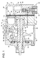
Referring first to Fig. 1, there is shown a compressor
of swash plate type. In Fig. 1, reference numeral 10 denotes a
cylinder block having a plurality of cylinder bores 12 formed so as
to extend in its axial direction such that the cylinder bores 12 are
arranged along a circle whose center lies on a centerline of the
cylinder block 10. Single-headed pistons generally indicated at
14 (hereinafter simply referred to as "piston 14") are reciprocably
received in the respective cylinder bores 12. To one of the
axially opposite end faces of the cylinder block 10, (the left end
face as seen in Fig. 1, which will be referred to as "front end
face"), there is attached a front housing 16. To the other end
face (the right end face as seen in Fig. 1, which will be referred to
as "rear end face"), there is attached a rear housing 18 through a
valve plate 20. The front housing 16, rear housing 18 and
cylinder block 10 cooperate to constitute a housing assembly of
the swash plate type compressor. The rear housing 18 and the
valve plate 20 cooperate to define a suction chamber 22 and a
discharge chamber 24, which are connected to a refrigerating
circuit (not shown) through an inlet 26 and an outlet 28,
respectively. The valve plate 20 has suction ports 32, suction
valves 34, discharge ports 36 and discharge valves 38.
A rotary drive shaft 50 is disposed in the cylinder
block 10 and the front housing 16 such that the axis of rotation of
the drive shaft 50 is aligned with the centerline of the cylinder
block 10. The drive shaft 50 is supported at its opposite end
portions by the front housing 16 and the cylinder block 10,
respectively, via respective bearings, such that the drive shaft 50
is rotatable relative to the front housing 16 and the cylinder
block 10. The cylinder block 10 has a central bearing hole 56
formed in a central portion thereof, and the bearing is disposed in
this central bearing hole 56, for supporting the drive shaft 50 at
its rear end portion. The front end portion of the drive shaft 50
is connected, through a clutch mechanism such as an
electromagnetic clutch, to an external drive source (not shown) in
the form of an engine of an automotive vehicle. In operation of
the compressor, the drive shaft 50 is connected through the
clutch mechanism to the vehicle engine in operation so that the
drive shaft 50 is rotated about its axis.
The rotary drive shaft 50 carries a swash plate 60
such that the swash plate 60 is axially movable and tiltable
relative to the drive shaft 50. The swash plate 60 has a central
hole 61 through which the drive shaft 50 extends. The inner
dimension of the central hole 61 as measured in a vertical
direction of Fig. 1 gradually increases in a direction from the
axially intermediate portion toward each of the axially opposite
ends, and the transverse cross sectional shape of the central hole
61 at each of the axially opposite ends is elongated. To the drive
shaft 50, there is fixed a rotary member 62 as a torque
transmitting member, which is held in engagement with the front
housing 16 through a thrust bearing 64. The swash plate 60 is
rotated with the drive shaft 50 by a hinge mechanism 66 during
rotation of the drive shaft 50. The hinge mechanism 66 guides
the swash plate 60 for its axial and tilting motions. The hinge
mechanism 66 includes a pair of support arms 67 fixed to the
rotary member 62, guide pins 69 which are formed on the swash
plate 60 and which slidably engage guide holes 68 formed in the
support arms 67, the central hole 61 of the swash plate 60, and
the outer circumferential surface of the drive shaft 50.
The piston 14 indicated above includes an engaging
portion 70 engaging the radially outer portion of the opposite
surfaces of the swash plate 60, and a head portion 72 formed
integrally with the engaging portion 70 and slidably fitted in the
corresponding cylinder bore 12. The head portion 72 of the
piston 14 in the present embodiment is made hollow, for thereby
reducing the weight of the piston 14. The head portion 72,
cylinder bore 12, and valve plate 20 cooperate with one another
to define a pressurizing chamber. The engaging portion 70
engages the radially outer portion of the opposite surfaces of the
swash plate 60 through a pair of part-spherical-crown shoes 76.
The shoes 76 will be described in greater detail.
The rotary motion of the swash plate 60 is converted
into a reciprocating linear motion of the piston 14 through the
shoes 76. A refrigerant gas in the suction chamber 22 is sucked
into the pressurizing chamber of the cylinder bore 12 through the
suction port 32 and the suction valve 34, when the piston 14 is
moved from its upper dead point to its lower dead point, that is,
when the piston 14 is in the suction stroke. The refrigerant gas
in the pressurizing chamber of the cylinder bore 12 is pressurized
by the piston 14 when the piston 14 is moved from its lower dead
point to its upper dead point, that is, when the piston 14 is in the
compression stroke. The pressurized refrigerant gas in the
pressurizing chamber is discharged into the discharge chamber
24 through the discharge port 36 and the discharge valve 38. A
reaction force acts on the piston 14 in the axial direction as a
result of compression of the refrigerant gas in the pressurizing
chamber. This compression reaction force is received by the
front housing 16 through the piston 14, swash plate 60, rotary
member 62 and thrust bearing 64.
The cylinder block 10 has an intake passage 80
formed therethrough for communication between the discharge
chamber 24 and a crank chamber 86 which is defined between
the front housing 16 and the cylinder block 10. The intake
passage 80 is connected to a solenoid-operated control valve 90
provided to control the pressure in the crank chamber 86. The
solenoid-operated control valve 90 includes a solenoid coil 92.
The amount of electric current applied to the solenoid coil 92 is
controlled depending upon the air conditioner load by a control
device not shown constituted principally by a computer.
The rotary drive shaft 50 has a bleeding passage
100 formed therethrough. The bleeding passage 100 is open at
one of its opposite ends to the central bearing hole 56, and is
open at the other end to the crank chamber 86. The central
bearing hole 56 communicates at its bottom with the suction
chamber 22 through a communication port 104.
The present swash plate type compressor is of
variable capacity type. By controlling the pressure in the crank
chamber 86 by utilizing a difference between the pressure in the
discharge chamber 24 as a high-pressure source and the pressure
in the suction chamber 22 as a low pressure source, a difference
between the pressure in the pressurizing chamber of the cylinder
bore 12 and the pressure in the crank chamber 86 is regulated to
change the angle of inclination of the swash plate 60 with respect
to a plane perpendicular to the axis of rotation of the drive shaft
50, for thereby changing the reciprocating stroke (suction and
compression strokes) of the piston 14, whereby the displacement
capacity of the compressor can be adjusted. Described in detail,
by energization and de-energization of the solenoid coil 92 of the
solenoid-operated control valve 90, the crank chamber 86 is
selectively connected to and disconnected from the discharge
chamber 24, so that the pressure in the crank chamber 86 is
controlled. The displacement capacity changing mechanism in
the swash plate type compressor of the present embodiment for
changing the displacement capacity of the compressor is
constituted by the hinge mechanism 66, cylinder bores 12,
pistons 14, suction chamber 22, discharge chamber 24, central
bearing hole 56, crank chamber 86, bleeding passage 100,
communication port 104, control device not shown, etc.
The cylinder block 10 and each piston 14 are formed
of an aluminum alloy. The piston 14 is coated at its outer
circumferential surface with a fluoro resin film which prevents a
direct contact of the aluminum alloy of the piston 14 with the
aluminum alloy of the cylinder block 10 so as to prevent seizure
therebetween, and makes it possible to minimize the amount of
clearance between the piston 14 and the cylinder bore 12. Other
materials may be used for the cylinder block 10, the piston 14,
and the coating film.
The end portion of the engaging portion 70 of the
piston 14, which is remote from the head portion 72, has a
U-shape in cross section. Described in detail, the engaging
portion 70 has a base section 124 which defines the bottom of the
U-shape, and a pair of substantially parallel arm sections 120,
122 which extend from the base section 124 in a direction
perpendicular to the axis of the piston 14. The two opposed
lateral walls of the U-shape of the engaging portion 70 have
respective recesses 128 which are opposed to each other. Each of
these recesses 128 is defined by a part-spherical inner surface of
the lateral wall. The part-spherical inner surfaces of the
recesses 128 are located on the same spherical surface.
As shown in Fig. 2, each of the pair of shoes 76 has a
substantially part-spherical crown shape, and includes a
generally convex part-spherical surface 132 and a generally flat
surface 138. Strictly speaking, the flat surface 138 is a slightly
convex curved surface (e.g., a convex part-spherical surface
having a considerably large radius of curvature), and includes a
tapered portion formed at a radially outer portion thereof. The
part-spherical surface 132 has a cylindrical portion formed
adjacent to the flat surface 138. The boundary between the
convex curved surface and the tapered portion, the boundary
between the tapered portion and the cylindrical portion, and the
boundary between the cylindrical portion and the part-spherical
convex surface, are rounded so as to have respective different
small radii of curvature. The pair of shoes 76 slidably engage
the part-spherical inner surfaces of the recesses 128 of the piston
14 at their part-spherical surfaces 132 and slidably engage the
radially outer portion of the opposite surfaces of the swash plate
60, i.e., the sliding surfaces 140, 142 of the swash plate 60, at
their flat surfaces 138. In other words, each shoe 76 slides on
the swash plate at its flat surface 138 and slides on the piston 14
at its part-spherical surface 132. The pair of shoes 76 are
designed such that their convex part-spherical surfaces 132 are
located on the same spherical surface. In other words, each shoe
76 has a part-spherical crown shape whose size is smaller than a
hemi-sphere by an amount corresponding to a half of the
thickness of the swash plate 60.
The shoe 76 includes a base body 146 and a metal
plating film 148 which covers the surface of the base body 146,
more specifically, the entire surface of the base body 146. In Fig.
2, the thickness of the metal plating film 148 is exaggerated for
easier understanding.
The base body 146 is formed of an Al-Si alloy, i.e., A
4032 according to the JIS H 4100, which contains aluminum as a
major component, and silicon. Various kinds of aluminum alloy
can be used as the material for the base body 146 of the present
shoe 76. The shoe may be produced according to the following
method, for instance. Initially, there is prepared a bar-shaped
member having a predetermined diameter. The bar-shaped
member is prepared by extruding a billet which is formed of an
aluminum alloy having a predetermined composition and which
is obtained by casting. The bar-shaped member is cut into a
plurality of pieces each having a predetermined length, by a
shearing device or a sawing machine. Each cut piece is
subjected to cold forging by using a press including a suitable die
assembly, so that the cut piece is formed into a roughly-shaped
precursor shoe. The method of producing the present shoe is not
limited to cold forging, but may be selected from among known
methods such as hot forging, casting, punching by a press,
machining, etc., and any suitable combination thereof.
Thereafter, the roughly-shaped precursor shoe may be subjected
to a suitable heat treatment. In general, a so-called T6
treatment (according to the JIS H 0001) is conducted, wherein
the roughly-shaped precursor shoe is subjected to an artificial
age hardening treatment after it has been subjected to a solution
heat treatment. The shoe which has been subjected to the T6
treatment exhibits significantly high degrees of strength and
hardness. The T6 treatment may be replaced with other heat
treatment such as a T7 treatment (according to JIS H 0001),
wherein the roughly-shaped precursor shoe which has been
subjected to the solution heat treatment is subjected to an
over-aging treatment which is conducted beyond conditions of the
artificial age hardening treatment at which the maximum
strength is obtained. After the heat treatment, a grinding
operation is effected on the roughly-shaped precursor shoe, so
that the roughly-shaped precursor shoe is formed into a
predetermined shape corresponding to that of the base body of
the shoe. Since the base body 146 of each shoe is formed of the
aluminum alloy, the swash plate type compressor equipped with
the shoes has a reduced weight.
The
metal plating film 148 formed on the surface of
the
shoe 76 may be selected from among those described in the
SUMMARY OF THE INVENTION. The advantages of the
respective plating films are described above. The method of
forming each of the plating films may be suitably selected from
among any known method. Where the
metal plating film 148 of
the
shoe 76 is constituted by a single film selected from among
those plating films, the composition and thickness of each plating
film is determined as described below. The following TABLE 1
indicates respective compositions of various electroless plating
films while TABLE 2 indicates respective compositions of various
electroplating films. The thickness of each of the electroless
plating films and electroplating films is as follows. Namely, the
lower limit of the film thickness is 10 µm, for assuring a
substantial effect of the plating film, more preferably 20 µm for
assuring a higher effect. The upper limit of the film thickness is
preferably 150 µm, more preferably 100 µm, for preventing
adverse influences due to an excessively large thickness value,
and for reducing the cost of manufacture. In the following
TABLE 1 and TABLE 2, "LOWER LIMIT 1" indicates a
preferable lower limit value indicative of the amount of each
element included in each plating film for assuring a substantial
effect by addition of that element, or by formation of the plating
film, while "LOWER LIMIT 2" indicates a more preferable lower
limit value indicative of the amount of each element included in
each plating film for assuring a higher effect. "UPPER LIMIT
2" indicates a preferable upper limit value indicative of the
amount of each element included in each plating film for
preventing adverse influences by addition of that element, or due
to an excessively large thickness value of the film, or for reducing
the cost of manufacture, while "UPPER LIMIT 1" indicates a
more preferable upper limit value indicative of the amount of
each element. In the following TABLE 1 and TABLE 2, the
element whose amount is indicated by a symbol "-" means a
major component of the plating film, and constitutes a
substantial part of the balance. In TABLE 1 and TABLE 2, the
amount of each element is represented by % by weight per 100 %
by weight of the plating film.
| <Electroless plating film> |
| | (unit: % by weight) |
| PLATING FILMS | ELEMENTS | LOWER LIMIT 1 | LOWER LIMIT 2 | UPPER LIMIT 1 | UPPER LIMIT 2 |
| Ni-P based film | Ni | - | - | - | - |
| P | ≤ 0.05 | ≤ 0.5 | ≥ 10 | ≥ 15 |
| Ni-B based film | Ni | - | - | - | - |
| B | ≤ 0.05 | ≤ 0.1 | ≥ 5 | ≥ 10 |
| Ni-P-B based film | Ni | - | - | - | - |
| P | ≤ 0.05 | ≤ 0.5 | ≥ 10 | ≥ 15 |
| B | ≤ 0.01 | ≤ 0.05 | ≥ 0.2 | ≥ 2 |
| Ni-P-W based film | Ni | - | - | - | - |
| P | ≤ 0.05 | ≤ 0.5 | ≥ 10 | ≥ 15 |
| W | ≤ 0.05 | ≤ 1 | ≥ 35 | ≥ 40 |
| Ni-B-W based film | Ni | - | - | - | - |
| B | ≤ 0.01 | ≤ 0.05 | ≥ 2 | ≥ 5 |
| W | ≤ 0.05 | ≤ 3 | ≥ 35 | ≥ 40 |
| Ni-P-B-W based film | Ni | - | - | - | - |
| P | ≤ 0.05 | ≤ 0.5 | ≥ 10 | ≥ 15 |
| B | ≤ 0.01 | ≤ 0.01 | ≥ 0.2 | ≥ 2 |
| W | ≤ 0.01 | ≤ 0.01 | ≥ 0.5 | ≥ 1 |
| Co-P based film | Co | - | - | - | - |
| P | ≤ 0.05 | ≤ 0.5 | ≥ 10 | ≥ 15 |
| Co-P-W based film | Co | - | - | - | - |
| P | ≤ 0.05 | ≤ 0.5 | ≥ 10 | ≥ 15 |
| W | ≤ 0.05 | ≤ 1 | ≥ 35 | ≥ 40 |
| Ni-Co based film | Ni | - | - | - | - |
| Co | < 0 | ≤ 10 | ≥ 90 | > 100 |
| Ni-Co-P based film | Ni | - | - | - | - |
| Co | ≤ 2 | ≤ 10 | ≥ 90 | ≥ 98 |
| P | ≤ 0.05 | ≤ 0.5 | ≥ 10 | ≥ 15 |
| <Electroplating film> |
| | (unit: % by weight) |
| PLATING FILM | ELEMENT | LOWER LIMIT 1 | LOWER LIMIT 2 | UPPER LIMIT 1 | UPPER LIMIT 2 |
| Ni based film | Ni | - | - | - | - |
| N-P based film | Ni | - | - | - | - |
| P | ≤ 0.1 | ≤ 0.2 | ≥ 10 | ≥ 15 |
| Ni-W based film | Ni | - | - | - | - |
| W | ≤ 0.05 | ≤ 1 | ≥ 40 | ≥ 50 |
| Ni-Fe based film | Ni | - | - | - | - |
| Fe | ≤ 1 | ≤ 2 | ≥ 30 | ≥ 40 |
| Ni-Mo-W based film | Ni | - | - | - | - |
| Mo | ≤ 0.05 | ≤ 1 | ≥ 40 | ≥ 50 |
| W | ≤ 0.05 | ≤ 1 | ≥ 40 | ≥ 50 |
| Fe based film | Fe | - | - | - | - |
| Fe-P based film | Fe | - | - | - | - |
| P | ≤ 0.05 | ≤ 0.1 | ≥ 5 | ≥ 10 |
| Fe-W based film | Fe | - | - | - | - |
| W | ≤ 0.05 | ≤ 1 | ≥ 60 | ≥ 70 |
| Fe-C based film | Fe | - | - | - | - |
| C | ≤ 0.05 | ≤ 0.1 | ≥ 5 | ≥ 7 |
| Fe-N based film | Fe | - | - | - | - |
| N | ≤ 0.05 | ≤ 0.1 | ≥ 5 | ≥ 7 |
| Cr based film | Cr | - | - | - | - |
| Cr-Mo based film | Cr | - | - | - | - |
| Mo | ≤ 0.05 | ≤ 1 | ≥ 40 | ≥ 50 |
| Co based film | Co | - | - | - | - |
| Co-W based film | Co | - | - | - | - |
| W | ≤ 0.05 | ≤ 1 | ≥ 40 | ≥ 50 |
As described above, the electroless plating film may
contain the PTFE therein. In other words, the PTFE may be
deposited together with the matrix phase of the plating film.
For obtaining a substantial effect by addition of the PTFE, the
PTFE is preferably included in the electroless plating film in an
amount of not smaller than 0.5 % by weight, more preferably not
smaller than 0.7 % by weight, per 100 % by weight of the
electroless plating film, for obtaining a higher effect. The
strength of the plating film is undesirably lowered by addition of
an excessively large amount of the PTFE. In view of this, it is
practically preferable that the PTFE is included in the plating
film in an amount of not greater than 12 % by weight, more
preferably not greater than 10 % by weight.
As described above, the electroless plating film may
be covered with at least one covering film which contains at least
one of Sn, TiCN, TiN, CrN, and TiAlN, so that the electroless
plating film and the at least one covering film formed thereon
cooperate to constitute the metal plating film 148. In this case,
the lower limit value of the thickness of each of the at least one
covering film is preferably 0.1 µm for obtaining a substantial
effect by provision of the covering film, more preferably 0.5 µm
for obtaining a higher effect. The upper limit value of the
thickness of each of the at least one covering film is preferably 5
µm, more preferably 4 µm, for preventing adverse influences due
to an excessively large thickness value and for reducing the cost
of manufacture.
The metal plating film may include at least one of
SiC, Si3N4, Al2O3, and CrC. The lower limit value of the amount
of each of those substances included in the metal plating film is
preferably 0.5 % by weight for obtaining a substantial effect by
addition of the substance, more preferably 1 % by weight for a
higher effect, per 100 % by weight of the metal plating film. The
upper limit value of the amount of each substance included in the
metal plating film is preferably 20 % by weight, more preferably
15 % by weight, per 100 % by weight of the metal plating film, for
preventing adverse influences due to addition of an excessively
large amount of the substance and for reducing the cost of
manufacture.
There will be next described a structure of the
swash plate 60. The swash plate 60 which engages the shoes 76
includes a base body 160 formed of spheroidal graphite cast iron,
generally called as ductile cast iron such as FCD 700 according to
the JIS G 5502. The swash plate 60 includes sliding surfaces
140, 142 which are to be held in sliding contact with the shoes 76.
(In Fig. 2, only one sliding surface 140 is shown.) At each
portion of the base body 160 of the swash plate 60 providing each
of the sliding surfaces 140, 142, a metal sprayed film in the form
of an aluminum sprayed film 162 and a lubricating film 164 are
formed in this order. In Fig. 2, the thickness of each of the
aluminum sprayed film 162 and the lubricating film 164 is
exaggerated for easier understanding. The lubricating film 164
is formed of a synthetic resin in the form of polyamideimide in
which MoS2 and graphite are dispersed. The lubricating film
164 has a thickness of 60 µm, and is effective to reduce the
friction between the sliding surfaces of the swash plate 60 and
the shoe 76. The aluminum sprayed film 162 has a thickness of
60 µm, and is effective to maintain good sliding characteristics of
the shoe 76 while preventing a direct contact of the base body 160
of the swash plate 60 with the shoe 76 even when the lubricating
film 164 is removed or separated due to abrasion, for instance.
The swash plate type compressor according to the
present embodiment exhibits good sliding characteristics and
assures smooth operation thereof owing to the advantages
provided by the shoe 76 and the swash plate 60 described above.
Accordingly, the present swash plate type compressor exhibits
excellent durability while maintaining good sliding
characteristics for a long period of service. The metal plating
film 148 formed on the surface of the shoe 76 is particularly
effective to improve the sliding characteristics of the compressor.
While the presently preferred embodiment of this
invention has been described above, for illustrative purpose only,
it is to be understood that the present invention is not limited to
the details of the illustrated embodiment. For example, the
principle of the invention is applicable to a swash plate type
compressor equipped with double-headed pistons each having
head portions on the opposite sides of the engaging portion which
engages the swash plate, or a swash plate type compressor of
fixed capacity type. It is to be understood that the present
invention may be embodied with various changes and
improvements such as those described in the SUMMARY OF
THE INVENTION, which may occur to those skilled in the art.
<Experiments for confirming the properties of the shoe for the
swash plate type compressor>
There were produced, according to the illustrated
embodiment, various swash plate type compressor shoes having
respective different metal plating films. The following
experiments were conducted on those shoes, for examining the
resistance of the shoes to seizure by using a test device, and the
sliding characteristics of some of the shoes by effecting a so-called
"dry-locking" test (which will be described in greater detail) while
the shoes are installed on the swash plate type compressor.
<Shoes used in the Experiments>
Initially, there were prepared base bodies of the
shoe by first forging, in a cold state, an Al-Si alloy corresponding
to the above-described A 4032, then conducting a grinding
operation after the T6 treatment. On the surfaces of the thus
prepared base bodies, there were formed respective different
metal plating films, which were surface-treated by buffing, so
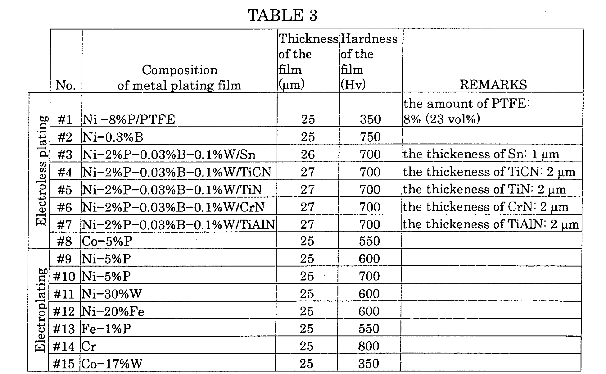
that fifteen shoes (#1 through #15) were produced. The shoes
#1-#8 include respective different electroless plating films while
the shoes #9-#15 include respective different electroplating films.
The following Table 3 shows the composition, the thickness, and
the hardness of each of the metal plating films formed on the
respective shoes. The amount of each element included in each
metal plating film is represented by % by weight. The shoe #1
includes an Ni-P based electroless nickel plating film which
contains the PTFE. The shoes #3-#7 include an Ni-P-B-W
based electroless nickel plating film, and respective different
covering films formed of Sn, TiCN, TiN, CrN, and TiAlN,
respectively. In each of the shoes #3-#7, the Ni-P-B-W based
electroless nickel plating film and the covering film cooperate to
provide the metal plating film. Accordingly, the thickness value
of the plating film in each of the shoes #3-#7 indicated in TABLE
3 corresponds to a sum of the thickness of the Ni-P-B-W based
electroless nickel plating film and the thickness of the covering
film, while the hardness value of the plating film in each of the
shoes #3-#7 indicated in TABLE 3 shows the hardness of the
Ni-P-B-W based electroless nickel plating film. In
"REMARKS" in TABLE 3, there are indicated the amount of
PTFE included in the plating film of the shoe #1, and the
thickness of each of the covering films respectively formed of Sn,
TiCN, TiN, CrN, and TiAlN, which covering films are provided on
the respective Ni-P-B-W based electroless nickel plating films
in the shoes #3-#7.
The following test was conducted on each of the
shoes #1-#15 produced as described above, for examining its
resistance to seizure. In the test, each
shoe 76 was pressed
against the sliding surface of a
suitable swash plate 60 by a
pressing jig 190 under a suitable load, as shown in Fig. 3. In
this state, the
swash plate 60 was rotated. For each
shoe 76,
there was measured a time from a moment of starting of the
sliding contact between the swash plate and the shoe and to a
moment at which the seizure took place was measured. (The
time is hereinafter referred to as "seizure time"). The
swash
plate 60 used in the test is similar to that described in the
DETAILED DESCRIPTION OF THE PREFERRED
EMBODIMENT. Namely, the
swash plate 60 is formed of the
above-described FCD 700, and includes the aluminum sprayed
film and the lubricating film formed in this order on each sliding
surface thereof. In the test, each shoe was subjected to the load
applied by the
pressing jig 190 such that the pressing force
applied to the shoe from the swash plate was 8.5 N/mm
2 which
corresponds to a quotient obtained by dividing the pressing load
applied to the shoe from the pressing jig, by the area of the flat
surface of the shoe. Further, the peripheral speed of the
swash
plate 60 on sliding surface which slides on the shoe was 10.5 m/s.
The test was conducted in the absence of the lubricating oil
between the swash plate and each shoe, i.e., in a non-lubricating
state. The results of the test are indicated in the following
TABLE 4 in which the above-indicated seizure time measured for
each shoe is shown. As is apparent from the results in TABLE 4,
the shoes #1-#15 showed relatively long seizure times in the
non-lubricating state. Accordingly, it is confirmed that all of the
shoes #1-#15 exhibit excellent seizure resistance. Thus, the
shoes #1-#15 are capable of exhibiting excellent sliding
characteristics.
| <Results of the test for examining the seizure resistance of the shoes> |
| No. | Seizure time (seconds) |
| #1 | 30 |
| #2 | 60 |
| #3 | 30 |
| #4 | 24 |
| #5 | 24 |
| #6 | 24 |
| #7 | 24 |
| #8 | 30 |
| #9 | 30 |
| #10 | 30 |
| #11 | 60 |
| #12 | 30 |
| #13 | 60 |
| #14 | 36 |
| #15 | 30 |
On the shoes #1, #2, #8, #11, #13, and #15 as
representative examples, a dry-locking test was conducted in the
following manner, by installing each shoe on the swash plate type
compressor. The swash plate type compressor used in the test is
similar to that described in the DESCRIPTION OF PREFERRED
EMBODIMENT, and a detailed explanation of which is dispensed
with. With each shoe being installed on the compressor, the
compressor was operated in the absence of the refrigerant, in
other words, in the non-lubricating state (i.e., in a dry state),
such that the rotating speed of the swash plate was 1000 rpm.
In this state, there was measured, for each shoe, a time from a
moment of starting of the compressor to a moment at which the
compressor was subjected to a so-called "dry-locking"
phenomenon. The dry-locking phenomenon means that the
compressor suffers form seizure between the swash plate and the
shoe while the swash plate and the shoe slide on each other in
the non-lubricating state, so that the swash plate and the shoe
are prevented from sliding on each other due to the seizure. In
the shoe which received the largest pressing force from the swash
plate, this pressing force was about 6.8N/mm
2 which corresponds
to a quotient obtained by dividing the load applied to the shoe
from the swash plate, by the area of the flat surface of the shoe.
The results of the test are shown in the following TABLE 5 in
which the above-indicated time for each shoe is shown.
| <Results of the dry-locking test> |
| No. | Time from a moment of starting of compressor to a moment at which compressor was subjected to dry-locking (seconds) |
| #1 | 42 |
| #2 | 50 |
| #8 | 50 |
| #11 | 39 |
| #13 | 35 |
| #15 | 32 |
As is apparent from the results indicated in the
above TABLE 5, the above-indicated time was more than 20
seconds in all cases when the compressor was equipped with the
selected shoes, i.e., #1, #2, #8, #11, #13, and #15. In the swash
plate type compressor, the shoes are lubricated by the lubricating
oil which is mixed or contained in the refrigerant. While the
compressor is not operated, the refrigerant is liquefied, and
stored in the compressor. In this case, the shoes are placed in
the substantially non-lubricating state. Since it takes about 20
seconds for the refrigerant to circulate in the compressor after
the starting of the operation of the compressor, the shoes are kept
in the non-lubricating state during the time period of about 20
seconds. As is apparent from the results indicated in TABLE 5,
the compressor did not suffer from the dry-locking phenomenon
during the time period (i.e., during the non-lubricating state) in
all cases when the compressor was equipped with the
above-indicated selected shoes. Accordingly, each of the shoes
exhibits excellent sliding characteristics without suffering any
trouble during its practical use.
A shoe for a swash plate type compressor disposed between a
swash plate and a corresponding one of a plurality of pistons, the
shoe being characterized by comprising: a base body (146) formed
of an aluminum alloy; and a metal plating film (148) which
covers at least a portion of a surface of the base body.