EP1319724B1 - Vacuum heat-treatment apparatus - Google Patents
Vacuum heat-treatment apparatus Download PDFInfo
- Publication number
- EP1319724B1 EP1319724B1 EP02027624A EP02027624A EP1319724B1 EP 1319724 B1 EP1319724 B1 EP 1319724B1 EP 02027624 A EP02027624 A EP 02027624A EP 02027624 A EP02027624 A EP 02027624A EP 1319724 B1 EP1319724 B1 EP 1319724B1
- Authority
- EP
- European Patent Office
- Prior art keywords
- workpiece
- chamber
- hermetic
- treatment apparatus
- treating
- Prior art date
- Legal status (The legal status is an assumption and is not a legal conclusion. Google has not performed a legal analysis and makes no representation as to the accuracy of the status listed.)
- Expired - Lifetime
Links
Images


Classifications
-
- C—CHEMISTRY; METALLURGY
- C21—METALLURGY OF IRON
- C21D—MODIFYING THE PHYSICAL STRUCTURE OF FERROUS METALS; GENERAL DEVICES FOR HEAT TREATMENT OF FERROUS OR NON-FERROUS METALS OR ALLOYS; MAKING METAL MALLEABLE, e.g. BY DECARBURISATION OR TEMPERING
- C21D1/00—General methods or devices for heat treatment, e.g. annealing, hardening, quenching or tempering
- C21D1/74—Methods of treatment in inert gas, controlled atmosphere, vacuum or pulverulent material
- C21D1/773—Methods of treatment in inert gas, controlled atmosphere, vacuum or pulverulent material under reduced pressure or vacuum
-
- C—CHEMISTRY; METALLURGY
- C21—METALLURGY OF IRON
- C21D—MODIFYING THE PHYSICAL STRUCTURE OF FERROUS METALS; GENERAL DEVICES FOR HEAT TREATMENT OF FERROUS OR NON-FERROUS METALS OR ALLOYS; MAKING METAL MALLEABLE, e.g. BY DECARBURISATION OR TEMPERING
- C21D9/00—Heat treatment, e.g. annealing, hardening, quenching or tempering, adapted for particular articles; Furnaces therefor
- C21D9/0006—Details, accessories not peculiar to any of the following furnaces
- C21D9/0018—Details, accessories not peculiar to any of the following furnaces for charging, discharging or manipulation of charge
-
- F—MECHANICAL ENGINEERING; LIGHTING; HEATING; WEAPONS; BLASTING
- F27—FURNACES; KILNS; OVENS; RETORTS
- F27B—FURNACES, KILNS, OVENS OR RETORTS IN GENERAL; OPEN SINTERING OR LIKE APPARATUS
- F27B17/00—Furnaces of a kind not covered by any of groups F27B1/00 - F27B15/00
- F27B17/0016—Chamber type furnaces
- F27B2017/0091—Series of chambers, e.g. associated in their use
-
- F—MECHANICAL ENGINEERING; LIGHTING; HEATING; WEAPONS; BLASTING
- F27—FURNACES; KILNS; OVENS; RETORTS
- F27B—FURNACES, KILNS, OVENS OR RETORTS IN GENERAL; OPEN SINTERING OR LIKE APPARATUS
- F27B9/00—Furnaces through which the charge is moved mechanically, e.g. of tunnel type; Similar furnaces in which the charge moves by gravity
- F27B9/02—Furnaces through which the charge is moved mechanically, e.g. of tunnel type; Similar furnaces in which the charge moves by gravity of multiple-track type; of multiple-chamber type; Combinations of furnaces
- F27B9/028—Multi-chamber type furnaces
-
- F—MECHANICAL ENGINEERING; LIGHTING; HEATING; WEAPONS; BLASTING
- F27—FURNACES; KILNS; OVENS; RETORTS
- F27B—FURNACES, KILNS, OVENS OR RETORTS IN GENERAL; OPEN SINTERING OR LIKE APPARATUS
- F27B9/00—Furnaces through which the charge is moved mechanically, e.g. of tunnel type; Similar furnaces in which the charge moves by gravity
- F27B9/04—Furnaces through which the charge is moved mechanically, e.g. of tunnel type; Similar furnaces in which the charge moves by gravity adapted for treating the charge in vacuum or special atmosphere
- F27B9/042—Vacuum furnaces
-
- F—MECHANICAL ENGINEERING; LIGHTING; HEATING; WEAPONS; BLASTING
- F27—FURNACES; KILNS; OVENS; RETORTS
- F27D—DETAILS OR ACCESSORIES OF FURNACES, KILNS, OVENS OR RETORTS, IN SO FAR AS THEY ARE OF KINDS OCCURRING IN MORE THAN ONE KIND OF FURNACE
- F27D3/00—Charging; Discharging; Manipulation of charge
- F27D3/0024—Charging; Discharging; Manipulation of charge of metallic workpieces
-
- Y—GENERAL TAGGING OF NEW TECHNOLOGICAL DEVELOPMENTS; GENERAL TAGGING OF CROSS-SECTIONAL TECHNOLOGIES SPANNING OVER SEVERAL SECTIONS OF THE IPC; TECHNICAL SUBJECTS COVERED BY FORMER USPC CROSS-REFERENCE ART COLLECTIONS [XRACs] AND DIGESTS
- Y10—TECHNICAL SUBJECTS COVERED BY FORMER USPC
- Y10S—TECHNICAL SUBJECTS COVERED BY FORMER USPC CROSS-REFERENCE ART COLLECTIONS [XRACs] AND DIGESTS
- Y10S414/00—Material or article handling
- Y10S414/135—Associated with semiconductor wafer handling
- Y10S414/137—Associated with semiconductor wafer handling including means for charging or discharging wafer cassette
- Y10S414/138—Wafers positioned vertically within cassette
Definitions
- This invention relates to a vacuum heat-treatment apparatus for heat-treating a metal workpiece under vacuum and more particularly to such an vacuum heat-treatment apparatus provided with a workpiece transfer mechanism for transferring a workpiece from a treating cell in the vacuum heat-treatment apparatus to another.
- Document JP-08178535 discloses a vacuum heat-treatment apparatus for heat-treating a workpiece in a treating cell comprising a hermetic chamber disposed at the center of the heat-treatment apparatus, a plurality of treating cells disposed along the periphery of the hermetic chamber, and a workpiece transfer mechanism which is disposed inside the hermetic chamber and transfers the workpiece from one of the treating cells to the hermetic chamber and from the hermetic chamber to one of the treating cells, wherein one of the treating cells is a cooling cell.
- the vacuum heat-treatment apparatus comprises a plurality of treating cells horizontally joined to a hermetic chamber having a horizontal shaft.
- An additional module in the form of a cylinder having therein an additional treating cell can be joined to one end of the hermetic chamber, whereby a desired number of treating cells can be added in a horizontal direction.
- U.S. Patent No.5,033,927 there has been disclosed another vacuum heat-treatment apparatus in U.S. Patent No.5,033,927 .
- a plurality of heating chambers (treating cells) are disposed in a star-like pattern in the upper portion of a doughnut-shaped hermetic chamber and a conveyor carriage which runs along a guide rail to transfer a workpiece from one treating cell to another is provided.
- the conveyor carriage runs below the treating cells and transfers the workpiece to a desired treating cell.
- the vacuum heat-treatment apparatuses of the prior art are disadvantageous in that as the number of the treating cells increases, the overall length of the vacuum heat-treatment apparatus horizontally increases and the time required to transfer the workpiece from a certain treating cell to another certain treating cell is elongated. Depending on the kind of the treatment, the workpiece must be transferred from one cell to another in a short time.
- a metal workpiece heated to a high temperature must be quickly introduced into a hardening oil reservoir or a gas cooling cell in an oil hardening step or a gas cooling step.
- the temperature of the workpiece lowers before the workpieces is introduced into the hardening oil reservoir or the gas cooling cell, which deteriorates the quality of the product obtained. Further since the vacuum heat-treatment apparatus is horizontally extended as the number of the treating cells increases, the space occupied by the vacuum heat-treatment apparatus increases in proportion to the number of the treating cells.
- the vacuum heat-treatment apparatus of the prior art are further disadvantageous in that the number of the treating cells is limited by the size of the hermetic chamber and increase of the throughput is limited.
- the vacuum heat-treatment apparatus for heat-treating a workpiece of the present invention since the oil hardening cell is positioned directly below the treating cell, the workpiece is directly and thus rapidly transferred from the treating cell to the oil hardening cell without passing through the hermetic chamber.
- the hermetic chamber and/or the treating cells may be provided in two or more stages in a vertical direction.
- the workpiece transfer mechanism may comprise, for instance, a workpiece container in which the workpiece is contained, a rotating mechanism which changes the horizontal direction of the workpiece container, and an elevator mechanism which moves up and down the workpiece container.
- the workpiece container may be provided with a telescopic lateral movement mechanism on which a basket containing therein the workpiece can be placed.
- an oil hardening cell disposed along the periphery of the hermetic chamber may be employed as a workpiece input/output cell for taking the workpiece in the vacuum heat-treatment apparatus and discharging the treated workpiece therefrom.
- One of the treating cells may be a gas cooling cell and the gas cooling cell may be employed as a workpiece input/output cell for taking the workpiece in the vacuum heat-treatment apparatus and discharging the treated workpiece therefrom.
- the upper and lower treating cells be angularly shifted with respect to each other by half a pitch, i.e., half of the angle included between adjacent two treating cells in the same stage, in order to reserve a space for accommodating a motor for a cooling fan or the like projecting from the top of the treating cell.
- the workpiece can be transferred from one treating cell to another in a short time by way of the hermetic chamber and accordingly a later treatment of a series of vacuum heat treatments can be started within a desired time, whereby a high quality product can be obtained.
- the number of the treating cells can be increased according to the required throughput without increasing the area occupied by the vacuum heat-treatment apparatus by increasing the number of the treating cells disposed along the periphery of the hermetic chamber or by providing the hermetic chamber and/or the treating cells in two or more stages in a vertical direction. That is, since the vacuum heat-treatment apparatus of the present invention allows to three-dimensionally increase the treating cells, the throughput can be increased in a limited area.
- the workpiece transfer mechanism comprises a workpiece container in which the workpiece is contained, a rotating mechanism which changes the horizontal direction of the workpiece container and an elevator mechanism which moves up and down the workpiece container, the workpiece can be transferred from one of the treating cells to another by a minimum movement of the workpiece transfer mechanism and accordingly, the workpiece can be freely transferred to a desired treating cell in a short time.
- the workpiece can be introduced into the oil hardening cell in substantially the same short time from any one of the treating cells in the same stage to be hardened, and accordingly, high quality products can be constantly obtained.
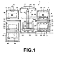
- a vacuum heat-treatment apparatus 1 in accordance with a first embodiment of the present invention comprises a cylindrical hermetic chamber 2 and a plurality of treating cell 4, 6, 8, 10, ⁇ which are disposed along the periphery of the hermetic chamber 2 in two stages.
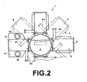
- the treating cells 4 and 8 in the upper stage are shown as aligned with the treating cells 6 and 10 in the lower stage for the purpose of simplicity in Figure 1, actually they are angularly shifted with respect to each other by half a pitch as shown in Figure 2.
- the "one pitch” as used here means the angle included between adjacent two treating cells in the same stage.
- the treating cells 4, 8, ⁇ in the upper stage (will be referred to as “the upper treating cells A”, hereinbelow) are disposed crosswise around the hermetic chamber 2 and the treating cells 6, 10, ⁇ in the lower stage (will be referred to as “the lower treating cells B", hereinbelow) are disposed crosswise around the hermetic chamber 2 with the lower cells B staggered with respect to the upper cells A by 45°.
- an additional treating cell 12 is connected to the treating cell 10 below the treating cell 10.
- openings 20 are formed in an upper portion of the periphery of the hermetic chamber 2 and a treating cell of the upper treating cells A is mounted on each of the openings 20 by means of a fastener such as a bolt (not shown) .
- a fastener such as a bolt (not shown)
- four rectangular openings 20 are formed in a lower portion of the periphery of the hermetic chamber 2 and a treating cell of the lower treating cells B is mounted on each of the openings 20 by means of a fastener such as a bolt (not shown) .
- Some of the openings 20 may be normally closed by a lid member and may be opened to mount thereon a treating cell when the treating cells are to be increased.
- the treating cells may be removably mounted on the hermetic chamber 2 or may be fixedly mounted on the hermetic chamber 2.
- the treating cells 4 and 6 are hermetic heating chambers and the treating cell 8 is a gas cooling chamber.
- Each of the hermetic heating chambers 4 and 6 comprises a heat insulating wall 22 provided along the inner surface of the chamber and a heater 24 which heats the inside of the chamber to a high temperature, thereby heating the workpiece.
- the heat insulating wall 22 is preferably of heat insulating material or heat-resistant material such as ceramics or graphite.
- the hermetic heating chambers 4 and 6 are respectively provided with temperature control means.
- the workpiece is, for instance, a metal part such as a gear or a shaft to be surface-hardened. The workpiece is placed on a table 28 in the hermetic heating chambers 4 and 6 with the heat insulating door 26 opened.
- Reference numeral 30 denotes a metal basket which contains therein the workpiece. Further, the hermetic heating chambers 4 and 6 are evacuated together with the hermetic chamber 2 when heating the workpiece.
- the gas cooling chamber 8 is provided with a chain-driven conveyor 32 and the workpiece heated in the hermetic heating chamber 4 or 6 is placed on the conveyor 32 and is hardened by gas cooling.
- the gas cooling chamber 8 is separated from the hermetic chamber 2 by a gas tight door 36 and the heated workpiece is transferred into the gas cooling chamber 8 through the hermetic chamber 2 with the door 36 opened.
- the doors 26 and 36 are opened, they are accommodated in door pockets 44 ( Figure 2) provided in the vicinity thereof.
- the gas cooling chamber 8 is further provided with an outer door 38 and a workpiece to be treated is transferred into the chamber 8 with the outer door 38 opened.
- the conveyor 32 is used when the workpiece to be treated is transferred into the chamber 8. Further, the treated workpiece can be transferred outward with the outer door 38 opened.
- the cooling chamber 8 doubles as a workpiece input/output cell for taking the workpiece in the vacuum heat-treatment apparatus 1 and discharging the treated workpiece therefrom.
- the treating cells 10 and 12 will be described, hereinbelow.
- the treating cells 10 and 12 are disposed in alignment with each other in a vertical direction.
- the upper cell 10 is provided with inner and outer gas tight doors 36 and 38 and is employed as a preparatory chamber, and the lower cell 12 is an oil hardening chamber having therein an oil reservoir.
- the preparatory chamber 10 is once evacuated.
- inert gas such as nitrogen gas or argon gas is filled into the preparatory chamber 10 until the pressure in the preparatory chamber 10 is equalized to the pressure in the hermetic chamber 2, which is normally held lower than the atmospheric pressure.
- the inner door 36 is opened and the workpiece is transferred to another treating cell by a workpiece transfer mechanism, which will be described later.
- the hermetic chamber 2 is evacuated when heating the workpiece in the heating chamber 4 or 6 as described above.
- the oil hardening chamber 12 below the preparatory chamber 10 is filled with hardening oil 40 and the heated workpiece is dipped in the hardening oil 40 to be hardened. That is, the inner door 36 of the preparatory chamber 10 is opened and the heated workpiece is once transferred into the preparatory chamber 10. Then the workpiece is suspended by a suspender (not shown), and the suspender is moved downward to dip the workpiece into the hardening oil 40. As shown in Figure 2, the oil hardening chamber 12 extends beyond the edges of the preparatory chamber 10 on opposite sides thereof, and the hardening oil 40 is stirred by downward-directed stirrers driven by motors 42 in order to uniformly cool the workpiece.
- each treating cell is provided with a vacuum valve (not shown) for evacuating the treating cell, a gas introduction valve (not shown) for introducing inert gas or carburizing gas as desired, and a bypass valve (not shown) for regulating the pressure in the treating cell.
- the hermetic chamber 2 will be described, hereinbelow.
- the hermetic chamber 2 is cylindrical in shape, and a workpiece transfer mechanism 51 having a frame-like rail member 52 is disposed inside the hermetic chamber 2.
- the rail member 52 comprises a vertical shaft 50 erected at the center of the hermetic chamber 2 and is rotated about the vertical shaft 50 by a rotating mechanism (not shown).
- a gondola (workpiece container) 54 is mounted on the rail member 52 to be moved up and down under the guidance of the rail member 52.
- the gondola 54 is moved up and down along the rail member 52 by an elevator mechanism including a cam follower 56 held by the rail member 52.
- the gondola 54 is rotated together with the rail member 52. Since the gondola 54 is rotated in the rail member 52, the moment required to rotate the gondola 54 may be small and accordingly, even a heavy workpiece can be rotated quickly. Further, the power required to rotated the workpiece may be small.
- a telescopic lateral movement mechanism 58 is mounted on the gondola 54.
- the lateral movement mechanism 58 comprises a folk-like telescopic arm 58a which can be extended in two or three stages.
- the telescopic arm 58a is normally in a contracted state so that the lateral movement mechanism 58 can be rotated in the hermetic chamber 2 together with the gondola 54.
- a tray 60 is mounted on the end of the telescopic arm 58a and the basket 30 is mounted on the tray 60 so that the basket 30 is moved laterally or horizontally as the telescopic arm 58a extends.
- the rotating mechanism, the elevator mechanism and the lateral movement mechanism 58 are driven by a driver (not shown) such as comprising an electric motor or a hydraulic cylinder.
- the vacuum heat treatment will be described, hereinbelow.
- the workpiece is transferred into, for instance, the treating cell 10, and the treating cell 10 is evacuated to purge air including oxygen therefrom in order to prevent oxidization of the workpiece.
- the workpiece is transferred to, for instance, the hermetic heating chamber 4, which has been held vacuum, by the workpiece transfer mechanism 51 through the hermetic chamber 2, which has been held vacuum.
- the hermetic heating chamber 4 the workpiece is heated. Though depending upon the size, material, amount and the like of the workpiece, the heating time generally exceeds two hours and sometimes ten and several times.
- the temperature of the workpiece gradually increases and carburizing gas, for instance, carbon-containing gas such as acetylene gas is introduced into the hermetic heating chamber 4 when the temperature of the workpiece reaches a predetermined temperature. Then the workpiece is kept heated for a predetermined time, whereby carbon components in the carburizing gas penetrates into the surface of the workpiece and the metal surface is converted into cementite. As the vacuum carburizing time is increased, the carbon components penetrates deeper into the workpiece. When the time required for the carbon components to penetrate to a desired depth lapses, the heating is ended.
- carburizing gas for instance, carbon-containing gas such as acetylene gas
- inert gas is supplied to the workpiece and a so-called diffusion step in which the carbon in the metal is diffused so that the carbon concentration in the metal surface is lowered is carried out.
- the vacuum heat treatment vacuum carburizing
- the inner door 26 of the hermetic heating chamber (treating cell) 4 is opened and the telescopic arm 58a of the lateral movement mechanism 58 is extended into the hermetic heating chamber 4. Then after the basket 30 in which the workpiece is contained is held by the tray 60 on the telescopic arm 58a, the telescopic arm 58a is contracted to transfer the basket 30 or the workpiece to the hermetic chamber 2.
- the gas tight door 36 of the gas cooling chamber 8 is opened and the telescopic arm 58a is extended to transfer the workpiece into the gas cooling chamber 8. Thereafter, the door 36 is shut to close the gas cooling chamber 8 in an airtight fashion.
- inert gas such as nitrogen gas or helium gas is filled into the gas cooling chamber 8 and the workpiece is cooled by the inert gas with the inert gas stirred by a fan 34 driven by an electric motor 35, whereby the workpiece is hardened (surface treatment).
- inert gas such as nitrogen gas or helium gas
- the workpiece is hardened by the use of gas, hardening progresses relatively slowly due to small specific heat of gas.
- the gas cooling process is employed.
- the gondola 54 is once lowered to the level of the lower treating cells B and the workpiece is once transferred to the preparatory chamber 10 by the lateral movement mechanism 58. Then the workpiece is dipped in the hardening oil 40 in the chamber 12 and is rapidly cooled so that the metal surface is converted into martensite from austenite.
- the temperature of the hardening oil 40 at this time is about 60 to 200°C and preferably 150°C. In order to prevent boiling of the hardening oil 40, the inner pressure of the hermetic oil hardening chamber 12 is increased.
- the hermetic heating chambers are more than the hardening chambers (the gas cooling chamber 8 and the oil hardening chamber 12) so that the treating cells are efficiently worked without idling the hardening chambers.
- Both the gas cooling chamber 8 and the hermetic oil hardening chamber 12 may be provided in the vacuum heat-treatment apparatus 1 or either of the gas cooling chamber 8 and the hermetic oil hardening chamber 12 may be provided in the vacuum heat-treatment apparatus 1 according to the application.
- one of the hardening chambers may be selected according to the material of the workpiece. For example, when the workpiece is SKD, the gas cooling chamber 8 is to be selected.
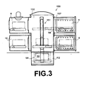
- a vacuum heat-treatment apparatus in accordance with a second embodiment of the present invention will be described with reference to Figure 3, hereinbelow.
- the elements analogous to those shown in Figure 1 are given the same reference numerals and will not be described here.
- the vacuum heat-treatment apparatus of this embodiment differs from that of the first embodiment in that a hermetic oil hardening chamber 112 is disposed below a hermetic chamber 102.
- the hermetic oil hardening chamber 112 is used, the pressure in the chamber 112 is increased and when hermetic heating chambers 4 and 6 are used, the chambers are evacuated. Accordingly, the hermetic chamber 102 is separated from the treating cell 4 or 6 by an air tight door 137.
- the application and the arrangement of the treating cells 4, 6, 8 and 10 are same as in the vacuum heat-treatment apparatus 1 of the first embodiment.
- the hermetic oil hardening chamber 112 is substantially at the same distance from all the treating cells in the same stage, whereby the workpiece can be hardened in a short time.
- workpieces vacuum-carburized in the treating cells 4 and 6 are transferred to the hermetic chamber 102 by the workpiece transfer mechanism 151 and then the workpiece can be immediately introduced into the hermetic oil hardening chamber 102 by lowering the gondola 54. That is, it is not necessary to once stop the gondola 54 at the level of another stage and then to move the workpiece in the gondola 54 to another treating cell by the lateral movement mechanism, which shortens the time required to dip the workpiece in the hardening oil.
- the workpiece transfer mechanism 151 is longer than the workpiece transfer mechanism 51 in the first embodiment and is arranged to be able to stop the gondola 54 at three levels opposed to the respective stages.
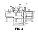
- a vacuum heat-treatment apparatus 200 in accordance with a third embodiment of the present invention will be described with reference to Figures 4 and 5, hereinbelow.
- a hermetic heating chamber 204 and a gas cooling chamber 208 are radially disposed about a hermetic chamber 202 in one stage as shown in Figure 5, and an oil hardening chamber 212 is disposed in a lower portion of the hermetic chamber 202.
- the hermetic chamber 202 is separated from each of the treating cells by an air tight door 261.
- the door pockets 244 in which the doors are accommodated projects upward of the treating cells.
- the hermetic chamber 202 is separated from each of the treating cells by an air tight door 261.
- These air tight doors 261 are for accommodating the difference in pressure between the hermetic chamber 202 and each of the treating cells.
- the upper portion of the hermetic chamber 202 is provided with a fan 265 driven by an electric motor 263 and may be employed as a gas cooling chamber.
- the path along which the workpiece is transferred is shown by chained line 266.
- the oil hardening cell 212 is disposed in a lower portion of the hermetic chamber 202, the workpiece can be hardened in a short time as in the second embodiment.
- a vacuum heat-treatment apparatus 300 in accordance with a fourth embodiment of the present invention will be described with reference to Figure 6, hereinbelow.
- a hermetic heating chamber 306 and a gas cooling chamber 308 are disposed about a one-stage hermetic chamber 302 and a hermetic oil hardening chamber 312 is disposed below the gas cooling chamber 308.
- the workpiece is treated in the same manner as in the vacuum heat-treatment apparatus 1 of the first embodiment.
- the treating cells may be arranged about a hermetic chamber two-dimensionally or in one stage. Also in this case, a workpiece transfer mechanism comprising an elevator mechanism for moving up and down the gondola and a rotating mechanism is provided in the hermetic chamber.
- treating cells can be increased in a circumferential direction or in a vertical direction, whereby the throughput can be increased without increasing the area occupied by the vacuum heat-treatment apparatus, and at the same time the workpiece can be dipped in the hardening oil within about one minute before the heated workpiece is cooled, whereby a high quality product can be obtained.
- the workpiece can be dipped in the hardening oil in a shorter time, this ensures to obtain a high quality product even if the workpiece is small and temperature drop of the workpiece is rapid.
- the hermetic chamber need not be cylindrical but may be, for instance, square or polygonal.
Landscapes
- Chemical & Material Sciences (AREA)
- Engineering & Computer Science (AREA)
- Physics & Mathematics (AREA)
- Thermal Sciences (AREA)
- Crystallography & Structural Chemistry (AREA)
- Mechanical Engineering (AREA)
- Materials Engineering (AREA)
- Metallurgy (AREA)
- Organic Chemistry (AREA)
- Tunnel Furnaces (AREA)
Description
- This invention relates to a vacuum heat-treatment apparatus for heat-treating a metal workpiece under vacuum and more particularly to such an vacuum heat-treatment apparatus provided with a workpiece transfer mechanism for transferring a workpiece from a treating cell in the vacuum heat-treatment apparatus to another.
- Document
JP-08178535 - As a vacuum heat-treatment apparatus, there has been known a modular vacuum heat-treatment apparatus disclosed in
U.S. Patent No. 6,065,964 . The vacuum heat-treatment apparatus comprises a plurality of treating cells horizontally joined to a hermetic chamber having a horizontal shaft. An additional module in the form of a cylinder having therein an additional treating cell can be joined to one end of the hermetic chamber, whereby a desired number of treating cells can be added in a horizontal direction. - Further, there has been disclosed another vacuum heat-treatment apparatus in
U.S. Patent No.5,033,927 . In the vacuum heat-treatment apparatus, a plurality of heating chambers (treating cells) are disposed in a star-like pattern in the upper portion of a doughnut-shaped hermetic chamber and a conveyor carriage which runs along a guide rail to transfer a workpiece from one treating cell to another is provided. The conveyor carriage runs below the treating cells and transfers the workpiece to a desired treating cell. - The vacuum heat-treatment apparatuses of the prior art are disadvantageous in that as the number of the treating cells increases, the overall length of the vacuum heat-treatment apparatus horizontally increases and the time required to transfer the workpiece from a certain treating cell to another certain treating cell is elongated. Depending on the kind of the treatment, the workpiece must be transferred from one cell to another in a short time. Especially in a vacuum heat-treatment apparatus, a metal workpiece heated to a high temperature must be quickly introduced into a hardening oil reservoir or a gas cooling cell in an oil hardening step or a gas cooling step. If it takes a long time to transfer the workpiece from the heating cell to the hardening oil reservoir or the gas cooling cell, the temperature of the workpiece lowers before the workpieces is introduced into the hardening oil reservoir or the gas cooling cell, which deteriorates the quality of the product obtained. Further since the vacuum heat-treatment apparatus is horizontally extended as the number of the treating cells increases, the space occupied by the vacuum heat-treatment apparatus increases in proportion to the number of the treating cells.
- The vacuum heat-treatment apparatus of the prior art are further disadvantageous in that the number of the treating cells is limited by the size of the hermetic chamber and increase of the throughput is limited.
- It is the object of the present invention to provide a vacuum heat-treatment apparatus for heat-treating a workpiece, wherein oil hardening treatment of the workpiece can be rapidly performed after having treated the workpiece in a treating cell.
- This object is fulfilled by a vacuum heat-treatment apparatus for heat-treating a workpiece having the features disclosed in
claim 1. Preferred embodiments are defined in the dependent claims. - With the vacuum heat-treatment apparatus for heat-treating a workpiece of the present invention, since the oil hardening cell is positioned directly below the treating cell, the workpiece is directly and thus rapidly transferred from the treating cell to the oil hardening cell without passing through the hermetic chamber.
- The hermetic chamber and/or the treating cells may be provided in two or more stages in a vertical direction.
- The workpiece transfer mechanism may comprise, for instance, a workpiece container in which the workpiece is contained, a rotating mechanism which changes the horizontal direction of the workpiece container, and an elevator mechanism which moves up and down the workpiece container.
- The workpiece container may be provided with a telescopic lateral movement mechanism on which a basket containing therein the workpiece can be placed. Further, an oil hardening cell disposed along the periphery of the hermetic chamber may be employed as a workpiece input/output cell for taking the workpiece in the vacuum heat-treatment apparatus and discharging the treated workpiece therefrom.
- One of the treating cells may be a gas cooling cell and the gas cooling cell may be employed as a workpiece input/output cell for taking the workpiece in the vacuum heat-treatment apparatus and discharging the treated workpiece therefrom.
- When the treating cells are provided in two or more stages, it is preferred that the upper and lower treating cells be angularly shifted with respect to each other by half a pitch, i.e., half of the angle included between adjacent two treating cells in the same stage, in order to reserve a space for accommodating a motor for a cooling fan or the like projecting from the top of the treating cell.
- In the vacuum heat-treatment apparatus of the present invention, since all the treating cells are disposed along the periphery of the hermetic chamber adjacent to the hermetic chamber, the workpiece can be transferred from one treating cell to another in a short time by way of the hermetic chamber and accordingly a later treatment of a series of vacuum heat treatments can be started within a desired time, whereby a high quality product can be obtained.
- Further, the number of the treating cells can be increased according to the required throughput without increasing the area occupied by the vacuum heat-treatment apparatus by increasing the number of the treating cells disposed along the periphery of the hermetic chamber or by providing the hermetic chamber and/or the treating cells in two or more stages in a vertical direction. That is, since the vacuum heat-treatment apparatus of the present invention allows to three-dimensionally increase the treating cells, the throughput can be increased in a limited area.
- When the workpiece transfer mechanism comprises a workpiece container in which the workpiece is contained, a rotating mechanism which changes the horizontal direction of the workpiece container and an elevator mechanism which moves up and down the workpiece container, the workpiece can be transferred from one of the treating cells to another by a minimum movement of the workpiece transfer mechanism and accordingly, the workpiece can be freely transferred to a desired treating cell in a short time.
- Further when the oil hardening cell is disposed in a lower portion of the hermetic chamber, the workpiece can be introduced into the oil hardening cell in substantially the same short time from any one of the treating cells in the same stage to be hardened, and accordingly, high quality products can be constantly obtained.
-
- Figure 1 is a cross-sectional view showing a vacuum heat-treatment apparatus in accordance with a first embodiment of the present invention,
- Figure 2 is a fragmentary plan view of the vacuum heat-treatment apparatus of the first embodiment,
- Figure 3 is a cross-sectional view similar to Figure 1 showing a vacuum heat-treatment apparatus in accordance with a second embodiment of the present invention,
- Figure 4 is a cross-sectional view similar to Figure 1 showing a vacuum heat-treatment apparatus in accordance with a third embodiment of the present invention,
- Figure 5 is a plan view of the vacuum heat-treatment apparatus in accordance with the third embodiment of the present invention, and
- Figure 6 is a cross-sectional view similar to Figure 1 showing a vacuum heat-treatment apparatus in accordance with a fourth embodiment of the present invention.
- As shown in Figures 1 and 2, a vacuum heat-
treatment apparatus 1 in accordance with a first embodiment of the present invention comprises a cylindricalhermetic chamber 2 and a plurality of treatingcell hermetic chamber 2 in two stages. Though the treatingcells cells cells hermetic chamber 2 and the treatingcells hermetic chamber 2 with the lower cells B staggered with respect to the upper cells A by 45°. Further, an additional treatingcell 12 is connected to the treatingcell 10 below the treatingcell 10. - Four
rectangular openings 20 are formed in an upper portion of the periphery of thehermetic chamber 2 and a treating cell of the upper treating cells A is mounted on each of theopenings 20 by means of a fastener such as a bolt (not shown) . Similarly, fourrectangular openings 20 are formed in a lower portion of the periphery of thehermetic chamber 2 and a treating cell of the lower treating cells B is mounted on each of theopenings 20 by means of a fastener such as a bolt (not shown) . Some of theopenings 20 may be normally closed by a lid member and may be opened to mount thereon a treating cell when the treating cells are to be increased. The treating cells may be removably mounted on thehermetic chamber 2 or may be fixedly mounted on thehermetic chamber 2. In this particular embodiment, the treatingcells cell 8 is a gas cooling chamber. - Each of the
hermetic heating chambers heat insulating wall 22 provided along the inner surface of the chamber and aheater 24 which heats the inside of the chamber to a high temperature, thereby heating the workpiece. Theheat insulating wall 22 is preferably of heat insulating material or heat-resistant material such as ceramics or graphite. Though not shown, thehermetic heating chambers hermetic heating chambers heat insulating door 26 opened. After theheat insulating door 26 is shut, the workpiece is heated to a predetermined temperature, e.g., 1000°C. Reference numeral 30 denotes a metal basket which contains therein the workpiece. Further, thehermetic heating chambers hermetic chamber 2 when heating the workpiece. - The
gas cooling chamber 8 is provided with a chain-drivenconveyor 32 and the workpiece heated in thehermetic heating chamber conveyor 32 and is hardened by gas cooling. Thegas cooling chamber 8 is separated from thehermetic chamber 2 by a gastight door 36 and the heated workpiece is transferred into thegas cooling chamber 8 through thehermetic chamber 2 with thedoor 36 opened. When thedoors gas cooling chamber 8 is further provided with anouter door 38 and a workpiece to be treated is transferred into thechamber 8 with theouter door 38 opened. Theconveyor 32 is used when the workpiece to be treated is transferred into thechamber 8. Further, the treated workpiece can be transferred outward with theouter door 38 opened. In this case, the coolingchamber 8 doubles as a workpiece input/output cell for taking the workpiece in the vacuum heat-treatment apparatus 1 and discharging the treated workpiece therefrom. - The treating
cells cells upper cell 10 is provided with inner and outer gastight doors lower cell 12 is an oil hardening chamber having therein an oil reservoir. After the workpiece is contained in thepreparatory chamber 10 through the openedouter door 38, thepreparatory chamber 10 is once evacuated. Thereafter, inert gas such as nitrogen gas or argon gas is filled into thepreparatory chamber 10 until the pressure in thepreparatory chamber 10 is equalized to the pressure in thehermetic chamber 2, which is normally held lower than the atmospheric pressure. Thereafter, theinner door 36 is opened and the workpiece is transferred to another treating cell by a workpiece transfer mechanism, which will be described later. Thehermetic chamber 2 is evacuated when heating the workpiece in theheating chamber - The
oil hardening chamber 12 below thepreparatory chamber 10 is filled with hardeningoil 40 and the heated workpiece is dipped in the hardeningoil 40 to be hardened. That is, theinner door 36 of thepreparatory chamber 10 is opened and the heated workpiece is once transferred into thepreparatory chamber 10. Then the workpiece is suspended by a suspender (not shown), and the suspender is moved downward to dip the workpiece into the hardeningoil 40. As shown in Figure 2, theoil hardening chamber 12 extends beyond the edges of thepreparatory chamber 10 on opposite sides thereof, and the hardeningoil 40 is stirred by downward-directed stirrers driven bymotors 42 in order to uniformly cool the workpiece. Themotors 42 are disposed in the parts of the hardeningchamber 12 extending beyond the edges of thepreparatory chamber 10 on opposite sides thereof. In the embodiment described above and the following embodiments, each treating cell is provided with a vacuum valve (not shown) for evacuating the treating cell, a gas introduction valve (not shown) for introducing inert gas or carburizing gas as desired, and a bypass valve (not shown) for regulating the pressure in the treating cell. - The
hermetic chamber 2 will be described, hereinbelow. As described above, thehermetic chamber 2 is cylindrical in shape, and aworkpiece transfer mechanism 51 having a frame-like rail member 52 is disposed inside thehermetic chamber 2. Therail member 52 comprises avertical shaft 50 erected at the center of thehermetic chamber 2 and is rotated about thevertical shaft 50 by a rotating mechanism (not shown). - A gondola (workpiece container) 54 is mounted on the
rail member 52 to be moved up and down under the guidance of therail member 52. Thegondola 54 is moved up and down along therail member 52 by an elevator mechanism including acam follower 56 held by therail member 52. When therail member 52 is rotated by the rotating mechanism, thegondola 54 is rotated together with therail member 52. Since thegondola 54 is rotated in therail member 52, the moment required to rotate thegondola 54 may be small and accordingly, even a heavy workpiece can be rotated quickly. Further, the power required to rotated the workpiece may be small. - A telescopic
lateral movement mechanism 58 is mounted on thegondola 54. Thelateral movement mechanism 58 comprises a folk-liketelescopic arm 58a which can be extended in two or three stages. Thetelescopic arm 58a is normally in a contracted state so that thelateral movement mechanism 58 can be rotated in thehermetic chamber 2 together with thegondola 54. Atray 60 is mounted on the end of thetelescopic arm 58a and thebasket 30 is mounted on thetray 60 so that thebasket 30 is moved laterally or horizontally as thetelescopic arm 58a extends. The rotating mechanism, the elevator mechanism and thelateral movement mechanism 58 are driven by a driver (not shown) such as comprising an electric motor or a hydraulic cylinder. - The vacuum heat treatment will be described, hereinbelow. The workpiece is transferred into, for instance, the treating
cell 10, and the treatingcell 10 is evacuated to purge air including oxygen therefrom in order to prevent oxidization of the workpiece. Thereafter, the workpiece is transferred to, for instance, thehermetic heating chamber 4, which has been held vacuum, by theworkpiece transfer mechanism 51 through thehermetic chamber 2, which has been held vacuum. In thehermetic heating chamber 4, the workpiece is heated. Though depending upon the size, material, amount and the like of the workpiece, the heating time generally exceeds two hours and sometimes ten and several times. - After the initiation of the heating, the temperature of the workpiece gradually increases and carburizing gas, for instance, carbon-containing gas such as acetylene gas is introduced into the
hermetic heating chamber 4 when the temperature of the workpiece reaches a predetermined temperature. Then the workpiece is kept heated for a predetermined time, whereby carbon components in the carburizing gas penetrates into the surface of the workpiece and the metal surface is converted into cementite. As the vacuum carburizing time is increased, the carbon components penetrates deeper into the workpiece. When the time required for the carbon components to penetrate to a desired depth lapses, the heating is ended. Thereafter, inert gas is supplied to the workpiece and a so-called diffusion step in which the carbon in the metal is diffused so that the carbon concentration in the metal surface is lowered is carried out. When the carbon concentration in the metal surface is lowered to a predetermined value, e.g., 0.8%, the vacuum heat treatment (vacuum carburizing) is ended. - When heat treatment is ended the
inner door 26 of the hermetic heating chamber (treating cell) 4 is opened and thetelescopic arm 58a of thelateral movement mechanism 58 is extended into thehermetic heating chamber 4. Then after thebasket 30 in which the workpiece is contained is held by thetray 60 on thetelescopic arm 58a, thetelescopic arm 58a is contracted to transfer thebasket 30 or the workpiece to thehermetic chamber 2. When the workpiece is to be subsequently gas-cooled, the gastight door 36 of thegas cooling chamber 8 is opened and thetelescopic arm 58a is extended to transfer the workpiece into thegas cooling chamber 8. Thereafter, thedoor 36 is shut to close thegas cooling chamber 8 in an airtight fashion. In this state, inert gas such as nitrogen gas or helium gas is filled into thegas cooling chamber 8 and the workpiece is cooled by the inert gas with the inert gas stirred by afan 34 driven by anelectric motor 35, whereby the workpiece is hardened (surface treatment). When the workpiece is hardened by the use of gas, hardening progresses relatively slowly due to small specific heat of gas. In the case where crack and/or deformation is generated in the workpiece when the workpiece is rapidly cooled, the gas cooling process is employed. - When the workpiece is to be subsequently oil-hardened in the hermetic oil-hardening
chamber 12, thegondola 54 is once lowered to the level of the lower treating cells B and the workpiece is once transferred to thepreparatory chamber 10 by thelateral movement mechanism 58. Then the workpiece is dipped in the hardeningoil 40 in thechamber 12 and is rapidly cooled so that the metal surface is converted into martensite from austenite. The temperature of the hardeningoil 40 at this time is about 60 to 200°C and preferably 150°C. In order to prevent boiling of the hardeningoil 40, the inner pressure of the hermeticoil hardening chamber 12 is increased. - Hardening normally requires 15 to 20 minutes whereas vacuum carburizing requires 2 or more hours as described above. Accordingly, in the vacuum heat-
treatment apparatus 1 of this embodiment, the hermetic heating chambers are more than the hardening chambers (thegas cooling chamber 8 and the oil hardening chamber 12) so that the treating cells are efficiently worked without idling the hardening chambers. Both thegas cooling chamber 8 and the hermeticoil hardening chamber 12 may be provided in the vacuum heat-treatment apparatus 1 or either of thegas cooling chamber 8 and the hermeticoil hardening chamber 12 may be provided in the vacuum heat-treatment apparatus 1 according to the application. In the case where both thegas cooling chamber 8 and the hermeticoil hardening chamber 12 are provided, one of the hardening chambers may be selected according to the material of the workpiece. For example, when the workpiece is SKD, thegas cooling chamber 8 is to be selected. - A vacuum heat-treatment apparatus in accordance with a second embodiment of the present invention will be described with reference to Figure 3, hereinbelow. The elements analogous to those shown in Figure 1 are given the same reference numerals and will not be described here. The vacuum heat-treatment apparatus of this embodiment differs from that of the first embodiment in that a hermetic
oil hardening chamber 112 is disposed below ahermetic chamber 102. When the hermeticoil hardening chamber 112 is used, the pressure in thechamber 112 is increased and whenhermetic heating chambers hermetic chamber 102 is separated from the treatingcell tight door 137. The application and the arrangement of the treatingcells treatment apparatus 1 of the first embodiment. - In this embodiment, since being disposed below the
hermetic chamber 2, the hermeticoil hardening chamber 112 is substantially at the same distance from all the treating cells in the same stage, whereby the workpiece can be hardened in a short time. For example, workpieces vacuum-carburized in the treatingcells hermetic chamber 102 by theworkpiece transfer mechanism 151 and then the workpiece can be immediately introduced into the hermeticoil hardening chamber 102 by lowering thegondola 54. That is, it is not necessary to once stop thegondola 54 at the level of another stage and then to move the workpiece in thegondola 54 to another treating cell by the lateral movement mechanism, which shortens the time required to dip the workpiece in the hardening oil. In this embodiment, theworkpiece transfer mechanism 151 is longer than theworkpiece transfer mechanism 51 in the first embodiment and is arranged to be able to stop thegondola 54 at three levels opposed to the respective stages. - A vacuum heat-
treatment apparatus 200 in accordance with a third embodiment of the present invention will be described with reference to Figures 4 and 5, hereinbelow. In the vacuum heat-treatment apparatus 200 of this embodiment, ahermetic heating chamber 204 and agas cooling chamber 208 are radially disposed about ahermetic chamber 202 in one stage as shown in Figure 5, and anoil hardening chamber 212 is disposed in a lower portion of thehermetic chamber 202. Thehermetic chamber 202 is separated from each of the treating cells by an airtight door 261. The door pockets 244 in which the doors are accommodated projects upward of the treating cells. Thehermetic chamber 202 is separated from each of the treating cells by an airtight door 261. These airtight doors 261 are for accommodating the difference in pressure between thehermetic chamber 202 and each of the treating cells. In this embodiment, the upper portion of thehermetic chamber 202 is provided with afan 265 driven by anelectric motor 263 and may be employed as a gas cooling chamber. In Figure 5, the path along which the workpiece is transferred is shown by chainedline 266. In this embodiment, since theoil hardening cell 212 is disposed in a lower portion of thehermetic chamber 202, the workpiece can be hardened in a short time as in the second embodiment. - A vacuum heat-
treatment apparatus 300 in accordance with a fourth embodiment of the present invention will be described with reference to Figure 6, hereinbelow. - In the vacuum heat-
treatment apparatus 300 of this embodiment, ahermetic heating chamber 306 and agas cooling chamber 308 are disposed about a one-stagehermetic chamber 302 and a hermeticoil hardening chamber 312 is disposed below thegas cooling chamber 308. In the vacuum heat-treatment apparatus 300, the workpiece is treated in the same manner as in the vacuum heat-treatment apparatus 1 of the first embodiment. - The treating cells may be arranged about a hermetic chamber two-dimensionally or in one stage. Also in this case, a workpiece transfer mechanism comprising an elevator mechanism for moving up and down the gondola and a rotating mechanism is provided in the hermetic chamber.
- As can be understood from the description above, in the vacuum heat-
treatment apparatuses - The hermetic chamber need not be cylindrical but may be, for instance, square or polygonal.
Claims (3)
- A vacuum heat-treatment apparatus for heat-treating a workpiece in a treating cell comprising a hermetic chamber (2) disposed at the center of the heat-treatment apparatus, a plurality of treating cells (4, 6, 8, 10, ...) disposed along the periphery of the hermetic chamber, and a workpiece transfer mechanism (51) which is disposed inside the hermetic chamber and transfers the workpiece from one of the treating cells to the hermetic chamber and from the hermetic chamber to one of the treating cells, wherein one of the treating cells is a cooling cell,
characterized in, that
one of the plurality of treating cells is positioned directly above and connected to an upper portion of an oil hardening cell to permit lowering/raising of a workpiece into the oil hardening cell from said one of the plurality of treating cells. - A vacuum heat-treatment apparatus as defined in Claim 1 in which the workpiece transfer mechanism (51) comprises a workpiece container in which the workpiece is contained, a rotating mechanism which changes the horizontal direction of the workpiece container (54), and an elevator mechanism (50, 52, 56) which moves up and down the workpiece container (54).
- A vacuum heat-treatment apparatus as defined in Claim 1 in which one of the treating cells (4, 6, 8,10,...) is a gas cooling cell.
Applications Claiming Priority (2)
| Application Number | Priority Date | Filing Date | Title |
|---|---|---|---|
| JP2001381296 | 2001-12-14 | ||
| JP2001381296A JP2003183728A (en) | 2001-12-14 | 2001-12-14 | Vacuum heat-treatment apparatus |
Publications (2)
| Publication Number | Publication Date |
|---|---|
| EP1319724A1 EP1319724A1 (en) | 2003-06-18 |
| EP1319724B1 true EP1319724B1 (en) | 2007-06-13 |
Family
ID=19187318
Family Applications (1)
| Application Number | Title | Priority Date | Filing Date |
|---|---|---|---|
| EP02027624A Expired - Lifetime EP1319724B1 (en) | 2001-12-14 | 2002-12-11 | Vacuum heat-treatment apparatus |
Country Status (4)
| Country | Link |
|---|---|
| US (1) | US6814573B2 (en) |
| EP (1) | EP1319724B1 (en) |
| JP (1) | JP2003183728A (en) |
| DE (1) | DE60220629T2 (en) |
Cited By (1)
| Publication number | Priority date | Publication date | Assignee | Title |
|---|---|---|---|---|
| EP3054019A1 (en) | 2015-02-04 | 2016-08-10 | Seco/Warwick S.A. | Multi-chamber furnace for vacuum carburizing and quenching of gears, shafts, rings and similar workpieces |
Families Citing this family (29)
| Publication number | Priority date | Publication date | Assignee | Title |
|---|---|---|---|---|
| US20040141832A1 (en) * | 2003-01-10 | 2004-07-22 | Jang Geun-Ha | Cluster device having dual structure |
| US20050016831A1 (en) * | 2003-07-24 | 2005-01-27 | Paganessi Joseph E. | Generation of acetylene for on-site use in carburization and other processes |
| US20070269297A1 (en) | 2003-11-10 | 2007-11-22 | Meulen Peter V D | Semiconductor wafer handling and transport |
| US20050223837A1 (en) * | 2003-11-10 | 2005-10-13 | Blueshift Technologies, Inc. | Methods and systems for driving robotic components of a semiconductor handling system |
| DE10359458B4 (en) * | 2003-12-17 | 2009-09-24 | Ald Vacuum Technologies Gmbh | Device for the chained heat treatment of workpieces under negative pressure |
| FR2874079B1 (en) * | 2004-08-06 | 2008-07-18 | Francis Pelissier | THERMOCHEMICAL CEMENT TREATMENT MACHINE |
| JP2006111907A (en) * | 2004-10-13 | 2006-04-27 | Fitting Kuze Co Ltd | Heat treatment apparatus |
| US7314777B2 (en) * | 2004-11-15 | 2008-01-01 | Honeywell International Inc. | Chip packaging systems and methods |
| KR100657560B1 (en) * | 2005-09-09 | 2006-12-14 | 한국생산기술연구원 | Oil pressure controlled heat treatment method for industrial blade |
| EP2541177A3 (en) * | 2005-11-23 | 2014-09-24 | Surface Combustion, Inc. | Fluid delivery system for an atmospheric furnace used for treating one or more articles |
| JP2008038221A (en) * | 2006-08-09 | 2008-02-21 | Nachi Fujikoshi Corp | Oil-cooled vacuum heat treatment furnace transfer device |
| EP2462253B1 (en) | 2009-08-07 | 2021-04-07 | Swagelok Company | Low temperature carburization under soft vacuum |
| CN101994006B (en) * | 2009-08-21 | 2013-02-13 | 清华大学 | Reduction device and hopper applied to reduction device |
| DE102009041041B4 (en) * | 2009-09-10 | 2011-07-14 | ALD Vacuum Technologies GmbH, 63450 | Method and apparatus for hardening workpieces, as well as work hardened workpieces |
| US10196730B2 (en) * | 2009-09-10 | 2019-02-05 | Ald Vacuum Technologies Gmbh | Method and device for hardening workpieces, and workpieces hardened according to the method |
| PL2607504T3 (en) * | 2011-12-23 | 2018-07-31 | Ipsen International Gmbh | Load transport mechanism for a multi-station heat treating system |
| JP6257527B2 (en) | 2012-01-20 | 2018-01-10 | スウエイジロク・カンパニー | Simultaneous flow of activated gas in low-temperature carburizing. |
| US9458519B2 (en) * | 2012-09-28 | 2016-10-04 | Ipsen, Inc. | Process for cooling a metal workload in a multimedia quench system |
| JP6212937B2 (en) * | 2013-05-09 | 2017-10-18 | 大同特殊鋼株式会社 | Vacuum quenching equipment |
| JP6229340B2 (en) * | 2013-07-17 | 2017-11-15 | 大同特殊鋼株式会社 | Vacuum sintering equipment |
| JP6403959B2 (en) * | 2014-03-06 | 2018-10-10 | Dowaサーモテック株式会社 | Carburizing and quenching equipment |
| JP6297471B2 (en) * | 2014-11-10 | 2018-03-20 | 中外炉工業株式会社 | Heat treatment equipment |
| JP6596703B2 (en) | 2015-03-04 | 2019-10-30 | 株式会社Ihi | Multi-chamber heat treatment equipment |
| WO2016189919A1 (en) | 2015-05-26 | 2016-12-01 | 株式会社Ihi | Heat treatment apparatus |
| JP6721466B2 (en) * | 2016-09-12 | 2020-07-15 | 株式会社Ihi | Heat treatment equipment |
| FR3073937B1 (en) * | 2017-11-21 | 2020-08-14 | Ceritherm | HEAT TREATMENT PLANT FOR THE MANUFACTURE OF INDUSTRIAL PRODUCTS. |
| WO2022169838A1 (en) * | 2021-02-05 | 2022-08-11 | Cummins Inc. | Methods and systems for vacuum and oil austempering in producing bainite |
| US11598579B2 (en) | 2021-07-01 | 2023-03-07 | King Yuan Dar Metal Enterprise Co., Ltd. | Continuous working system |
| KR102882447B1 (en) * | 2023-09-13 | 2025-11-05 | 이광래 | Continuous heat treatment apparatus |
Family Cites Families (19)
| Publication number | Priority date | Publication date | Assignee | Title |
|---|---|---|---|---|
| JPS6047505B2 (en) | 1980-12-23 | 1985-10-22 | 日本酸素株式会社 | Continuous vacuum heating furnace |
| FR2537260B3 (en) | 1982-12-02 | 1985-11-22 | Traitement Sous Vide | MULTICELLULAR OVEN FOR THE THERMAL, THERMOCHEMICAL OR ELECTROTHERMAL TREATMENT OF METALS UNDER RAREFIED ATMOSPHERE |
| US4634375A (en) * | 1985-03-11 | 1987-01-06 | Hailey Robert W | Heating and handling system for metal consolidation process |
| US4951601A (en) * | 1986-12-19 | 1990-08-28 | Applied Materials, Inc. | Multi-chamber integrated process system |
| JPS63183121A (en) * | 1987-01-24 | 1988-07-28 | Shimadzu Corp | Pressure oil quenching method |
| FR2644567A1 (en) * | 1989-03-17 | 1990-09-21 | Etudes Const Mecaniques | DEVICE FOR EXECUTING HEAT TREATMENTS CONTINUOUS IN VACUUM CONTINUOUS |
| DE3935014A1 (en) * | 1989-10-20 | 1991-04-25 | Pfeiffer Vakuumtechnik | MULTI-CHAMBER VACUUM SYSTEM |
| US5404894A (en) * | 1992-05-20 | 1995-04-11 | Tokyo Electron Kabushiki Kaisha | Conveyor apparatus |
| ES2090893T3 (en) | 1993-01-28 | 1996-10-16 | Applied Materials Inc | VACUUM TREATMENT APPARATUS THAT HAS AN IMPROVED PRODUCTION CAPACITY. |
| JPH0741848A (en) * | 1993-07-27 | 1995-02-10 | Demu Tec Kk | Heat treatment furnace apparatus |
| JP3490791B2 (en) | 1994-12-20 | 2004-01-26 | 光洋サーモシステム株式会社 | Multi-chamber heat treatment furnace |
| JPH093533A (en) * | 1995-06-21 | 1997-01-07 | Daido Steel Co Ltd | Heat chamber cooling device for heat treatment |
| KR100310249B1 (en) * | 1995-08-05 | 2001-12-17 | 엔도 마코토 | Substrate Processing Equipment |
| JP3895000B2 (en) * | 1996-06-06 | 2007-03-22 | Dowaホールディングス株式会社 | Carburizing, quenching and tempering method and apparatus |
| FR2771754B1 (en) | 1997-12-02 | 2000-02-11 | Etudes Const Mecaniques | MODULAR VACUUM HEAT TREATMENT PLANT |
| JP3656701B2 (en) * | 1998-03-23 | 2005-06-08 | 東京エレクトロン株式会社 | Processing equipment |
| KR100265287B1 (en) * | 1998-04-21 | 2000-10-02 | 윤종용 | Multi-chamber system for etching equipment for manufacturing semiconductor device |
| JP2965038B1 (en) * | 1998-09-21 | 1999-10-18 | 日新電機株式会社 | Vacuum processing equipment |
| US6234788B1 (en) * | 1998-11-05 | 2001-05-22 | Applied Science And Technology, Inc. | Disk furnace for thermal processing |
-
2001
- 2001-12-14 JP JP2001381296A patent/JP2003183728A/en active Pending
-
2002
- 2002-12-11 DE DE60220629T patent/DE60220629T2/en not_active Expired - Lifetime
- 2002-12-11 EP EP02027624A patent/EP1319724B1/en not_active Expired - Lifetime
- 2002-12-11 US US10/315,941 patent/US6814573B2/en not_active Expired - Lifetime
Cited By (1)
| Publication number | Priority date | Publication date | Assignee | Title |
|---|---|---|---|---|
| EP3054019A1 (en) | 2015-02-04 | 2016-08-10 | Seco/Warwick S.A. | Multi-chamber furnace for vacuum carburizing and quenching of gears, shafts, rings and similar workpieces |
Also Published As
| Publication number | Publication date |
|---|---|
| US20030113186A1 (en) | 2003-06-19 |
| JP2003183728A (en) | 2003-07-03 |
| EP1319724A1 (en) | 2003-06-18 |
| US6814573B2 (en) | 2004-11-09 |
| DE60220629D1 (en) | 2007-07-26 |
| DE60220629T2 (en) | 2008-02-14 |
Similar Documents
| Publication | Publication Date | Title |
|---|---|---|
| EP1319724B1 (en) | Vacuum heat-treatment apparatus | |
| US5722825A (en) | Device for heat-treating metallic work pieces in a vacuum | |
| EP0359756B1 (en) | Rotary hearth multi-chamber multi-purpose furnace system | |
| JP2013087359A (en) | Apparatus for quenching material to be treated | |
| CN1926249A (en) | Double chamber type heat treatment furnace | |
| JP2005009702A (en) | Multi-cell type vacuum heat treating apparatus | |
| KR101544091B1 (en) | Heat Treatment Device Using The Vertical Movement Cooling Method | |
| KR100964994B1 (en) | Installation for the heat-treatment of parts | |
| JP4428268B2 (en) | Heat treatment furnace | |
| KR960016162B1 (en) | Furnace | |
| US4915361A (en) | Rapid thermochemical treatment automatic installation | |
| JP4947783B2 (en) | Vacuum heat treatment equipment | |
| US4086050A (en) | Method and apparatus for gas circulation in a heat treating furnace | |
| EP0530513B1 (en) | Heat treat furnace system for performing different carburizing processes simultaneously | |
| JP6341625B2 (en) | Heat treatment equipment | |
| JP4385213B2 (en) | Batch heat treatment equipment | |
| JP4537522B2 (en) | Intermittently driven vacuum carburizing furnace | |
| DE19635257C1 (en) | Compact orbital heat treatment furnace | |
| JP2013091818A (en) | Quenching apparatus for material to be treated | |
| US4596610A (en) | Hardening metal parts | |
| DE3233361A1 (en) | Continuous electric furnace for the chemical/thermal treatment of steel components | |
| RU2040753C1 (en) | Workpieces thermal treatment line | |
| US7833471B2 (en) | Carburizing apparatus and carburizing method | |
| US6210156B1 (en) | Heat treatment material handling unit | |
| KR100195971B1 (en) | Vertical moving continuous heat treatment furnace |
Legal Events
| Date | Code | Title | Description |
|---|---|---|---|
| PUAI | Public reference made under article 153(3) epc to a published international application that has entered the european phase |
Free format text: ORIGINAL CODE: 0009012 |
|
| AK | Designated contracting states |
Designated state(s): AT BE BG CH CY CZ DE DK EE ES FI FR GB GR IE IT LI LU MC NL PT SE SI SK TR |
|
| AX | Request for extension of the european patent |
Extension state: AL LT LV MK RO |
|
| 17P | Request for examination filed |
Effective date: 20031218 |
|
| AKX | Designation fees paid |
Designated state(s): DE FR GB |
|
| GRAP | Despatch of communication of intention to grant a patent |
Free format text: ORIGINAL CODE: EPIDOSNIGR1 |
|
| GRAS | Grant fee paid |
Free format text: ORIGINAL CODE: EPIDOSNIGR3 |
|
| GRAA | (expected) grant |
Free format text: ORIGINAL CODE: 0009210 |
|
| AK | Designated contracting states |
Kind code of ref document: B1 Designated state(s): DE FR GB |
|
| REG | Reference to a national code |
Ref country code: GB Ref legal event code: FG4D |
|
| REF | Corresponds to: |
Ref document number: 60220629 Country of ref document: DE Date of ref document: 20070726 Kind code of ref document: P |
|
| ET | Fr: translation filed | ||
| PLBE | No opposition filed within time limit |
Free format text: ORIGINAL CODE: 0009261 |
|
| STAA | Information on the status of an ep patent application or granted ep patent |
Free format text: STATUS: NO OPPOSITION FILED WITHIN TIME LIMIT |
|
| 26N | No opposition filed |
Effective date: 20080314 |
|
| REG | Reference to a national code |
Ref country code: GB Ref legal event code: 732E Free format text: REGISTERED BETWEEN 20100225 AND 20100303 |
|
| REG | Reference to a national code |
Ref country code: FR Ref legal event code: TP |
|
| PGFP | Annual fee paid to national office [announced via postgrant information from national office to epo] |
Ref country code: DE Payment date: 20131204 Year of fee payment: 12 Ref country code: GB Payment date: 20131211 Year of fee payment: 12 |
|
| PGFP | Annual fee paid to national office [announced via postgrant information from national office to epo] |
Ref country code: FR Payment date: 20131209 Year of fee payment: 12 |
|
| REG | Reference to a national code |
Ref country code: DE Ref legal event code: R119 Ref document number: 60220629 Country of ref document: DE |
|
| GBPC | Gb: european patent ceased through non-payment of renewal fee |
Effective date: 20141211 |
|
| REG | Reference to a national code |
Ref country code: FR Ref legal event code: ST Effective date: 20150831 |
|
| PG25 | Lapsed in a contracting state [announced via postgrant information from national office to epo] |
Ref country code: GB Free format text: LAPSE BECAUSE OF NON-PAYMENT OF DUE FEES Effective date: 20141211 Ref country code: DE Free format text: LAPSE BECAUSE OF NON-PAYMENT OF DUE FEES Effective date: 20150701 |
|
| PG25 | Lapsed in a contracting state [announced via postgrant information from national office to epo] |
Ref country code: FR Free format text: LAPSE BECAUSE OF NON-PAYMENT OF DUE FEES Effective date: 20141231 |