EP1319459A2 - Wire electric-discharge machining apparatus - Google Patents
Wire electric-discharge machining apparatus Download PDFInfo
- Publication number
- EP1319459A2 EP1319459A2 EP02010115A EP02010115A EP1319459A2 EP 1319459 A2 EP1319459 A2 EP 1319459A2 EP 02010115 A EP02010115 A EP 02010115A EP 02010115 A EP02010115 A EP 02010115A EP 1319459 A2 EP1319459 A2 EP 1319459A2
- Authority
- EP
- European Patent Office
- Prior art keywords
- feed rate
- voltage
- relative feed
- workpiece
- short circuit
- Prior art date
- Legal status (The legal status is an assumption and is not a legal conclusion. Google has not performed a legal analysis and makes no representation as to the accuracy of the status listed.)
- Granted
Links
- 238000003754 machining Methods 0.000 title claims abstract description 163
- 230000008859 change Effects 0.000 claims description 27
- 230000007423 decrease Effects 0.000 claims description 4
- 238000010586 diagram Methods 0.000 description 12
- 238000000034 method Methods 0.000 description 11
- 238000005259 measurement Methods 0.000 description 8
- 238000004364 calculation method Methods 0.000 description 6
- 239000012530 fluid Substances 0.000 description 5
- 230000003746 surface roughness Effects 0.000 description 5
- 238000010276 construction Methods 0.000 description 4
- 230000003247 decreasing effect Effects 0.000 description 4
- 239000000463 material Substances 0.000 description 4
- 230000015572 biosynthetic process Effects 0.000 description 3
- 230000000694 effects Effects 0.000 description 2
- 238000012887 quadratic function Methods 0.000 description 2
- 230000004044 response Effects 0.000 description 2
- 229910001369 Brass Inorganic materials 0.000 description 1
- 229910000831 Steel Inorganic materials 0.000 description 1
- 230000002411 adverse Effects 0.000 description 1
- 230000009286 beneficial effect Effects 0.000 description 1
- 239000010951 brass Substances 0.000 description 1
- 238000012986 modification Methods 0.000 description 1
- 230000004048 modification Effects 0.000 description 1
- 230000008569 process Effects 0.000 description 1
- 238000011084 recovery Methods 0.000 description 1
- 239000010959 steel Substances 0.000 description 1
Images


Classifications
-
- B—PERFORMING OPERATIONS; TRANSPORTING
- B23—MACHINE TOOLS; METAL-WORKING NOT OTHERWISE PROVIDED FOR
- B23H—WORKING OF METAL BY THE ACTION OF A HIGH CONCENTRATION OF ELECTRIC CURRENT ON A WORKPIECE USING AN ELECTRODE WHICH TAKES THE PLACE OF A TOOL; SUCH WORKING COMBINED WITH OTHER FORMS OF WORKING OF METAL
- B23H7/00—Processes or apparatus applicable to both electrical discharge machining and electrochemical machining
- B23H7/02—Wire-cutting
- B23H7/04—Apparatus for supplying current to working gap; Electric circuits specially adapted therefor
-
- B—PERFORMING OPERATIONS; TRANSPORTING
- B23—MACHINE TOOLS; METAL-WORKING NOT OTHERWISE PROVIDED FOR
- B23H—WORKING OF METAL BY THE ACTION OF A HIGH CONCENTRATION OF ELECTRIC CURRENT ON A WORKPIECE USING AN ELECTRODE WHICH TAKES THE PLACE OF A TOOL; SUCH WORKING COMBINED WITH OTHER FORMS OF WORKING OF METAL
- B23H1/00—Electrical discharge machining, i.e. removing metal with a series of rapidly recurring electrical discharges between an electrode and a workpiece in the presence of a fluid dielectric
- B23H1/02—Electric circuits specially adapted therefor, e.g. power supply, control, preventing short circuits or other abnormal discharges
- B23H1/024—Detection of, and response to, abnormal gap conditions, e.g. short circuits
-
- B—PERFORMING OPERATIONS; TRANSPORTING
- B23—MACHINE TOOLS; METAL-WORKING NOT OTHERWISE PROVIDED FOR
- B23H—WORKING OF METAL BY THE ACTION OF A HIGH CONCENTRATION OF ELECTRIC CURRENT ON A WORKPIECE USING AN ELECTRODE WHICH TAKES THE PLACE OF A TOOL; SUCH WORKING COMBINED WITH OTHER FORMS OF WORKING OF METAL
- B23H7/00—Processes or apparatus applicable to both electrical discharge machining and electrochemical machining
- B23H7/02—Wire-cutting
- B23H7/06—Control of the travel curve of the relative movement between electrode and workpiece
- B23H7/065—Electric circuits specially adapted therefor
-
- B—PERFORMING OPERATIONS; TRANSPORTING
- B23—MACHINE TOOLS; METAL-WORKING NOT OTHERWISE PROVIDED FOR
- B23H—WORKING OF METAL BY THE ACTION OF A HIGH CONCENTRATION OF ELECTRIC CURRENT ON A WORKPIECE USING AN ELECTRODE WHICH TAKES THE PLACE OF A TOOL; SUCH WORKING COMBINED WITH OTHER FORMS OF WORKING OF METAL
- B23H2600/00—Machining conditions
- B23H2600/10—Switching of machining conditions during machining
- B23H2600/12—Switching from rough cutting to finish machining
Definitions
- the present invention relates to a wire electric-discharge machining apparatus.
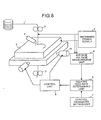
- Fig. 8 is a block diagram that shows a wire electric-discharge machining apparatus based on a conventional art of this type.
- reference numeral 1 denotes a wire electrode, 2 a workpiece, 3 a wire supplying unit, 4 a dielectric fluid supplying unit, 5 a machining power supply, 6 an average voltage measurement unit, 7 a control parameter setting unit, 8 a relative feed rate determining unit, 9 a control unit, and 10 a driving unit.
- the wire supplying unit 3 feeds out the wire electrode 1 at an appropriate speed, and allows this to travel while giving an appropriate tension to the wire electrode 1.
- the dielectric fluid supplying unit 4 supplies adielectric fluid in a minute gap between the wire electrode 1 and the workpiece 2.
- the machiningpower supply 5 applies a pulse-like voltage between the wire electrode 1 and the workpiece 2 so that a discharge is generated between the wire electrode 1 and the workpiece 2.
- the average voltage measurement unit 6 measures an average voltage between the wire electrode 1 and the workpiece 2.
- the control parameter setting unit 7 sets a reference voltage and a target feed rate based on machining conditions set by the user.
- the relative feed rate determining unit 8 calculates a relative feed rate between the wire electrode 1 and the workpiece 2 by using the average voltage measured by the average voltage measurement unit 6 and the reference voltage and the target feed rate set by the control parameter setting unit 7 to supply the relative feed rate to the control unit 9.
- the control unit 9 relatively moves the wire electrode 1 and the workpiece 2 at the relative feed rate thus calculated through the driving unit 10.
- the relative feed rate determining unit 8 compares the measured average voltage obtained by the average voltage measurement unit 6 with a preset short circuit reference voltage.
- the short circuit reference voltage is a voltage used as a reference when a case in which the measured average voltage is below this voltage is determined that the generation of a discharge is impossible because the wire electrode 1 and the workpiece 2 are in contact with each other.
- the above-mentioned relative feed rate determining unit 8 generally sets the short circuit reference voltage to a value in the range of 10 to 15 V.
- the relative feed rate determining unit 8 sets the relative feed rate to a comparatively great negative value. Consequently, the wire electrode 1 and the workpiece 2 are separated from each other at a high speed, thereby making it possible to eliminate a short circuit state between them.
- the relative feed rate determining unit 8 sets the relative feed rate by executing the following calculations.
- the relative feed rate determining unit 8 divides the target feed rate given from the control parameter setting unit 7 by a difference between the reference voltage and the short circuit reference voltage to obtain a proportional constant.
- the relative feed rate determining unit 8 calculates a difference (hereinafter, simply referred to as error voltage) between the measured average voltage and the reference voltage, multiplies this error voltage by the proportional constant, and obtains a value as a compensation feed rate.
- the relative feed rate determining unit 8 adds the target feed rate to this compensation feed rate to decide a relative feed rate.
- the relative feed rate is made to be proportional to the difference between the measured average voltage and the short circuit reference voltage, and the relative feed rate is set to be equal to the target feed rate when the measured average voltage is equal to the reference voltage.
- the above-mentioned conventional art has a problem such that the value of the proportional constant is decided uniquely by the values of the target feed rate and the reference voltage.
- the proportional constant is a constant to determine the degree in which the relative feed rate is changed in response to variations in the measured average voltage, that is, the constant by which control gain is decided, so that this is the most basic and essential constant to define the machining control characteristic.
- the constant is uniquely decided by the target feed rate and the reference voltage that are decided according to the settings of a machining plate thickness and the machining power supply 5, and therefore there is a problem that desired control characteristics cannot be set freely.
- the control gain becomes constant in all the areas.
- the response property is intended to be improved by increasing the proportional constant in the vicinity of the reference voltage in order to increase the machining speed, the amount of overshoot is inevitably increased as well.
- the measured average voltage tends to easily go below the short circuit reference voltage in the vicinity of the short circuit reference voltage.
- the relative feed rate becomes frequently negative to repeat short circuit and opening, thus the machining state may become quite unstable.
- a modified technique in which a voltage that makes the relative feed rate zero is set to be higher than the short circuit reference voltage.
- the proportional constant is obtained not through calculation of the target feed rate and the reference voltage, but through multiplication of the error voltage by this proportional constant using the preset value to set a value as a compensation feed rate. Further, the target feed rate is added to this compensation feed rate to decide the relative feed rate.
- the compensation feed rate is negative with its absolute value being greater than the target feed rate
- the relative feed rate obtained through the calculations becomes negative, and in this case, zero is set as the relative feed rate .
- the reason why the relative feed rate is set to zero when the relative feed rate obtained through the calculations is negative is explained as follows .
- the wire electrode 1 When the relative feed rate is set negative, the wire electrode 1 backs up on the path.
- Fig. 11 is a schematic diagram that shows how finishing machining is carried out in the wire discharge machining
- Fig. 12 is a schematic diagram that shows a case in which there is waviness on the previously machined surface
- Fig. 13 is a schematic diagram that shows the profile of the machined surface after the finishing by applying the conventional modified technique to the previously machined surface with the waviness.
- the previously machined surface 100 having a greater surface roughness is subjected to finishing with smaller energy to form a currently machined surface 101 having a smaller surface roughness.
- great waviness derived from various external disturbances, exists on the previously machined surface 100 having a greater surface roughness.
- the depth of the recessed portion 101a formed on the currently machined surface 101 is small in comparison with the height of the peak 100a that exists on the previously machined surface 100, it is certain that the degree of the machined surface roughness gradually reduces through the finishing machining.
- the machining volume performed in the next finishing machining that is, the distance between the currently machined surface 101 and the subsequently machined surface 102 needs to be set with a greater margin. This also causes an increase in the machining volume.
- a reverse phenomenon as follows is generally experienced in the wire electric-discharge machining.
- the reverse phenomenon in the machining volume is such that an insufficiently machined portion on the previously machined surface 100 is subjected to an excessive machining, while an excessively machined portion is subjected to an insufficient machining.
- the previously machined surface 100 having a great surface roughness is machined by using very small energy so that the number of finishing steps is minimized as small as possible to improve the total machining speed, the above-mentioned reverse phenomenon comes to appear more frequently, causing a great adverse effect on the machining speed.
- the measured average voltage is not allowed to rise because a short circuit current actually flows through the machining dusts due to imperfect short circuit although the measured average voltage is not below the short circuit reference voltage. This case corresponds to the state in the range (b) shown in Fig. 10, in which the wire electrode 1 is being stopped and thereby the machining does not progress at all.
- It is an object of this invention is to provide a wire electric-discharge machining apparatus capable of desirably setting a control gain so as to stabilize the machining state, and of improving the machining speed.
- the wire electric-discharge machining apparatus comprises a relative feed rate determining unit that decides a relative feed rate between a wire electrode and a workpiece based on a measured voltage between the wire electrode and the workpiece.
- This wire electric-discharge machining apparatus carries out machining on the workpiece by generating a discharge between the wire electrode and the workpiece and relatively moving the wire electrode and the workpiece at the relative feed rate decided by the relative feed rate determining unit.
- the relative feed rate determining unit outputs a target feed rate as a target value when the measured voltage is equal to a preset reference voltage, and outputs a positive relative feed rate according to preset conditions, when the measured voltage exceeds a predetermined short circuit reference voltage but is below a switching voltage that is preliminarily set between the short circuit reference voltage and the reference voltage.
- the wire electrode and the workpiece move at the target feed rate, and when the measured voltage exceeds the short circuit reference voltage, the wire electrode and the workpiece always move at the positive relative feed rate.
- the wire electric-discharge machining apparatus comprises a relative feed rate determining unit that decides a relative feed rate between a wire electrode and a workpiece based on a measured voltage between the wire electrode and the workpiece.
- This wire electric-discharge machining apparatus carries out machining on the workpiece by generating a discharge between the wire electrode and the workpiece and relatively moving the wire electrode and the workpiece at the relative feed rate decided by the relative feed rate determining unit.
- the relative feed rate determining unit outputs a positive relative feed rate in which an amount of change per unit voltage change becomes smaller as a difference between the measured voltage and the short circuit reference voltage decreases.
- the wire electrode and the workpiece when the measured voltage exceeds the short circuit reference voltage, the wire electrode and the workpiece always move at the positive relative feed rate in which an amount of change per unit voltage change becomes smaller as the difference between the measured voltage and the short circuit reference voltage decreases.
- Fig. 1 is a diagram that shows a schematic construction of the wire electric-discharge machining apparatus according to the first embodiment of the present invention
- Fig. 2 is a graph that shows the relationship between the measured voltage and the relative feed rate in the wire electric-discharge machining apparatus according to the first embodiment
- Fig. 3 is a schematic diagram that shows the profile of the machined surface after the finishing carried out by the wire electric-discharge machining apparatus according to the first embodiment when there is waviness on the previously machined surface
- Fig. 4 is a graph that shows the relationship between the measured voltage and the relative feed rate in the wire electric-discharge machining apparatus according to the second embodiment of the present invention
- Fig. 5 is a graph that shows the relationship between the measured voltage and the relative feed rate in the wire electric-discharge machining apparatus according to the third embodiment of the present invention.
- Fig. 6 is a graph that shows the relationship between the measured voltage and the relative feed rate in the wire electric-discharge machining apparatus according to the fourth embodiment of the present invention.
- Fig. 7 is a graph that shows the relationship between the measured voltage and the relative feed rate in the wire electric-discharge machining apparatus according to the fifth embodiment of the present invention.
- Fig. 8 is a diagram that schematically shows the construction of the conventional wire electric-discharge machining apparatus
- Fig. 9 is a graph that shows the relationship between the measured voltage and the relative feed rate in the conventional wire electric-discharge machining apparatus
- Fig. 10 is a graph that shows the relationship between the measured voltage and the relative feed rate in the conventional modified technique
- Fig. 11 is a schematic diagram that shows the sequence of processes in the finishing in the wire discharge machining
- Fig. 12 is a schematic diagram that shows the case in which waviness exist on the previously machined surface
- Fig. 13 is a schematic diagram that shows the profile of the machined surface after the finishing carried out by using the conventional modified technique on the previously machined surface with waviness.
- Fig. 1 is a diagram that shows the construction of the wire electric-discharge machining apparatus according to the first embodiment of the present invention.
- the wire electric-discharge machining apparatus shown here is provided with the following parts as main components, the wire supplying unit 3 which supplies the wire electrode 1, the dielectric fluid supplying unit 4 which supplies a dielectric fluid in a minute gap between the wire electrode 1 and the workpiece 2, the machining power supply 5 which applies a pulse-like voltage between the wire electrode 1 and the workpiece 2 to generate a discharge between the wire electrode 1 and the workpiece 2, the average voltage measurement unit 6 which measures an average voltage between the wire electrode 1 and the workpiece 2, the control parameter setting unit 7 which sets a reference voltage and a target feed rate based on machining conditions set by the user, the relative feed rate determining unit 8 which calculates a relative feed rate between the wire electrode 1 and the workpiece 2 based on the results of measurements by the average voltage measurement unit 6 and the contents of the settings in
- the control parameter switching unit 12 calculates a control parameter (proportional constant) switching voltage as a switching voltage based on a control parameter (proportional constant) switching speed as a switching speed preliminarily set by the user.
- the control parameter (proportional constant) switching speed is a relative feed rate between the wire electrode 1 and the workpiece 2 that indicates a switching point of control parameters (proportional constant) , and is set to a value lower than the target feed rate set by the control parameter setting unit 7.
- the control parameter switching voltage is a voltage between the wire electrode 1 and the workpiece 2 that corresponds to the switching speed of the control parameter (proportional constant), and is calculated as follows.
- Vx Vr - (Fr - Fx)/A.
- control parameter switching unit 12 carries out processing of preliminarily calculating the second proportional constant so that it becomes a control parameter (proportional constant) when the measured average voltage between the wire electrode 1 and the workpiece 2 is equal to the control parameter (proportional constant) switching voltage and that the relative feed rate becomes zero when the measured average voltage is equal to the short circuit reference voltage.
- the second proportional constant is B ( ⁇ A) and the short circuit reference voltage is Vs
- the short circuit reference voltage mentioned here is a reference voltage used to determine that, when the measured average voltage is below this reference voltage, the generation of a discharge is impossible due to contact between the wire electrode 1 and the workpiece 2, as is described in the section on the conventional art.
- the control parameter (proportional constant) switching voltage and the second proportional constant have been set in the control parameter switching unit 12 in such a manner as explained above.
- the control parameter switching unit 12 switches the proportional constant of the relative feed rate determining unit 8 to the second proportional constant when the average voltage measured by the average voltage measurement unit 6 is not more than the control parameter (proportional constant) switching voltage, while it returns the proportional constant to the originally set proportional constant A when the measured average voltage exceeds the control parameter (proportional constant) switching voltage.
- the relative feed rate determining unit 8 decides a relative feed rate by using the set proportional constant A or the second proportional constant B that are switched by the control parameter switching unit 12 on demand.
- the relative feed rate determining unit 8 sets the relative feed rate to a comparatively great negative value. Accordingly, the wire electrode 1 and the workpiece 2 are separated from each other at a high speed, thereby making it possible to eliminate the short circuit state between them.
- the relative feed rate determining unit 8 calculates a difference between the measured average voltage and the proportional constant switchingvoltage (hereinafter, referred to simply as a first error voltage) , and this first error voltage is multiplied by the second proportional constant B to obtain a compensation feed rate. Lastly, the proportional constant switching speed is added to this compensation feed rate to decide the relative feed rate.
- the reference speed decision unit 8 calculates a difference between the measured average voltage and the reference voltage (hereinafter, referred to simply as a second error voltage) , and this second error voltage is multiplied by the above-mentioned set proportional constant A to obtain a compensation feed rate. Lastly, the target feed rate is added to this compensation feed rate to decide the relative feed rate.
- the relationship between the measured average voltage and the reference moving speed, obtained by the relative feed rate determining unit 8, is shown in the graph of Fig. 2.
- the relative feed rate in the range (a) of Fig. 2 in which the relative feed rate exceeds the proportional constant switching speed, the relative feed rate is increased or decreased in proportion to the second error voltage, and when the measured average voltage is equal to the reference voltage, the relative feed rate is set to be equal to the target feed rate.
- the relative feed rate is increased or decreased in proportion to the first error voltage.
- the amount of change in the relative feed rate per unit voltage change is smaller than the range (a) of Fig. 2.
- the wire electrode 1 when the measured average voltage is below the short circuit reference voltage, the wire electrode 1 is allowed to back at a high speed with respect to the workpiece 2.
- a positive relative feed rate is applied between the wire electrode 1 and the workpiece 2 at any time other than the occurrence of short circuit.
- the wire electrode 1 passes through a peak 100a of waviness prior to formation of a recessed portion in front of the peak 100a of the waviness existing on the previously machined surface 100.
- the relative feed rate drops since the measured average voltage drops, and thereby the machining progresses in such a manner as to make the height of the peak 100a lower without causing any short circuit.
- Fig. 3 is a schematic diagram that shows the profile of the machined surface after a finishing has been carried out using the wire electric-discharge machining apparatus according to the first embodiment when the previously machined surface 100 has waviness.
- the application of the wire electric-discharge machining apparatus of the first embodiment makes it possible to effectively avoid the reverse phenomenon of the machining volume, thus, it becomes possible to reduce the machining volume required from the currently machined surface 101 to the subsequently machined face 102 so that the finishing volume is cut to a great degree, thereby making it possible to greatly improve the total machining speed.
- the prediction makes it possible to reduce a margin to be allowed in the machining amount of the next finishing and also decide the amount of the electrode offset in the finishing independent from the presence or absence of the waviness.
- the relative feed rate corresponding to the measured average voltage between the short circuit reference voltage and the control parameter switching voltage is decided so as to be proportional to the difference between the control parameter switching voltage and the measured average voltage. This arrangement is beneficial in providing easier calculations when the control parameter switching voltage is reversely calculated from the control parameter switching speed.
- the present invention is not limited by this, and when the measured average voltage is equal to the control parameter switching voltage, the relative feed rate serves as the control parameter switching speed. When it is located between the control parameter switching voltage and the short circuit reference voltage, any function may be applied as a function which calculates the relative feed rate as long as the relative feed rate is positive.
- Fig. 4 is a graph that shows the relationship between the measured voltage and the relative feed rate in a wire electric-discharge machining apparatus according to the second embodiment.
- the relative feed rate with respect to the increase in the measured average voltage is allowed to have a relationship represented by a high-order function such as a quadratic function, etc., that is, a relationship in which the amount of change in the relative feed rate per unit voltage change is gradually decreased as the measured average voltage comes closer to the short circuit reference voltage.
- the above-mentioned high-order function is set so that when the measured average voltage becomes equal to the short circuit reference voltage, the relative feed rate becomes zero and when the measured average voltage becomes equal to the control parameter switching voltage, the relative feed rate is equal to the control parameter switching speed. Since the other arrangements are the same as those of the wire electric-discharge machining apparatus of the first embodiment, the explanation thereof is omitted.
- such a wire electric-discharge machining apparatus of the second embodiment also, it is possible to perform an appropriate machining control according to various machining conditions because the control gain to be applied to the driving unit 10 is set according to a desired high-order function independent from the target feed rate and reference voltage. Moreover, when the measured average voltage has reached the short circuit reference voltage, the relative feed rate between the wire electrode 1 and the workpiece 2 becomes zero, and therefore there is no possibility of the measured average voltage going below the short circuit reference voltage, thus, it becomes possible to stabilize the machining state.
- a positive relative feed rate is applied between the wire electrode 1 and the workpiece 2 at any time other than the occurrence of short circuit.
- the wire electric-discharge machining apparatus is designed in such a manner that a positive relative feed rate is applied between the wire electrode 1 and the workpiece 2 at any time other than the occurrence of short circuit. Therefore, like in the first embodiment, it is possible to effectively avoid the reverse phenomenon in the machining volume, thus, it becomes possible to largely reduce the machining volume required from the currently machined surface 101 to the subsequently machined surface 102 so that the finishing volume is cut to a great degree, thereby making it possible to greatly improve the total machining speed. Moreover, since only the height of the peak 100a of the waviness is made lower and since no recessed portion is newly formed, it becomes possible to easily predict the height of the waviness after the machining.
- the wire electric-discharge machining apparatus since the amount of change in the relative feed rate between the wire electrode and the workpiece is gradually reduced as the measured voltage comes closer to the short circuit reference voltage, it is possible to widen the low-gain control area in comparison with the first embodiment when the difference between the short circuit reference voltage and the control parameter switching voltage is the same. Thus, it is possible to positively prevent short circuit between the wire electrode 1 and the workpiece 2.
- Fig. 5 is a graph that shows the relationship between the measured voltage and the relative feed rate in a wire electric-discharge machining apparatus according to the third embodiment.
- the device when the measured average voltage exceeds the short circuit reference voltage but is below the control parameter switching voltage, the device is allowed to output a constant relative feed rate independent from the increase of the measured average voltage.
- the constant relative feed rate may be set by multiplying the target feed rate by a predetermined ratio. In this case, the ratio is preferably set to approximately 1/10 or the like so that the relative feed rate is a minute value.
- the other arrangements are the same as those of the wire electric-discharge machining apparatus shown in the first embodiment, and therefore the respective explanations are omitted.
- control gain to be supplied to the driving unit 10 is desirably set independent from the target feed rate and the reference voltage. Therefore, it is possible to carry out an appropriate machining control according to various machining conditions. Moreover, when the measured average voltage has reached the short circuit reference voltage, the relative feed rate between the wire electrode 1 and the workpiece 2 becomes zero to eliminate the possibility of measured average voltage going below the short circuit reference voltage. Thus, it becomes possible to stabilize the machining state.
- a positive relative feed rate is applied between the wire electrode 1 and the workpiece 2 at any time other than the occurrence of short circuit.
- the wire electric-discharge machining apparatus is designed in such a manner that a positive relative feed rate is applied between the wire electrode 1 and the workpiece 2 at any time other than the occurrence of short circuit. Therefore, like in the first embodiment, it is possible to effectively avoid the reverse phenomenon in the machining volume . Thus, it becomes possible to reduce the machining volume required from the currently machined surface 101 to the subsequently machined face 102 so that the finishing volume is cut to a great degree, thereby making it possible to greatly improve the total machining speed.
- the wire electrode 1 and the workpiece 2 move at a constant moving speed, and thereby the relative feed rate between the wire electrode 1 and the workpiece 2 can be calculated more easily.
- Fig. 6 is a graph that shows the relationship between the measured voltage and the relative feed rate in a wire electric-discharge machining apparatus according to the fourth embodiment.
- the relative feed rate with respect to the increase in the measured average voltage is allowed to have a relationship represented by a high-order function such as a quadratic function, etc. That is, the amount of change in the relative feed rate per unit voltage change is gradually increased as the measured average voltage comes closer to the short circuit reference voltage.
- a relative feed rate having an amount of change per unit voltage change that is greater than the case in which the measured voltage exceeds the control parameter switching voltage is output, immediately before the measured voltage has reached the control parameter switching voltage.
- the above-mentioned high-order function is set so that the relative feed rate is set to zero when the measured average voltage becomes equal to the short circuit reference voltage , and the relative feed rate is equal to the control parameter switching speed when the measured average voltage becomes equal to the control parameter switching voltage. Since the other arrangements are the same as those of the wire electric-discharge machining apparatus of the first embodiment, the explanation thereof is omitted.
- the control gain to be applied to the driving unit 10 can be set according to a desired high-order function independent from the target feed rate and reference voltage. Therefore, it is possible to carry out an appropriate machining control according to various machining conditions. Moreover, when the measured average voltage has reached the short circuit reference voltage, the relative feed rate between the wire electrode 1 and the workpiece 2 becomes zero. Therefore, there is no possibility of the measured average voltage going below the short circuit reference voltage, thus, it becomes possible to stabilize the machining state.
- a positive relative feed rate is applied between the wire electrode 1 and the workpiece 2 at any time other than the occurrence of short circuit.
- the wire electric-discharge machining apparatus is designed in such a manner that a positive relative feed rate is applied between the wire electrode 1 and the workpiece 2 at any time other than the occurrence of short circuit. Therefore, like in the first embodiment, it is possible to effectively avoid the reverse phenomenon in the machining volume, thus, it becomes possible to reduce the machining volume required from the currently machined surface 101 to the subsequently machined face 102 so that the finishing volume is cut to a great degree, thereby making it possible to greatly improve the total machining speed. Moreover, since only the height of the peak 100a of the waviness is made lower and since no recessed portion is newly formed, it becomes possible to easily predict the height of the waviness after the machining.
- Fig. 7 is a graph that shows the relationship between the measured voltage and the relative feed rate in a wire electric-discharge machining apparatus according to the fifth embodiment.
- the increase in the relative feed rate is made proportional to the increase in the measured average voltage .
- the present invention does not necessarily require such a proportional relationship. Therefore, in the fifth embodiment shown in Fig.
- the device when the measured average voltage is not less than the short circuit reference voltage, the device is allowed to use a single high-order function that increases the degree of an increase in the relative feed rate with respect to the increase in the measured average voltage as a difference from the corresponding short circuit reference voltage increases.
- the above-mentioned high-order function is set so that the relative feed rate becomes zero when the measured average voltage becomes equal to the short circuit reference voltage, and the relative feed rate is equal to the target feed rate when the measured average voltage becomes equal to the reference voltage. Since the other arrangements are the same as those of the wire electric-discharge machining apparatus of the first embodiment, the explanation thereof is omitted.
- a positive relative feed rate is applied between the wire electrode 1 and the workpiece 2 at any time other than the occurrence of short circuit.
- the wire electric-discharge machining apparatus is designed in such a manner that a positive relative feed rate is applied between the wire electrode 1 and the workpiece 2 at any time other than the occurrence of short circuit. Therefore, like in the first embodiment, it is possible to effectively avoid the reverse phenomenon in the machining volume. Thus, it becomes possible to reduce the machining volume required from the currently machined surface 101 to the subsequently machined surface 102 so that the finishing volume is cut to a great degree, thereby making it possible to greatly improve the total machining speed. Moreover, since only the height of the peak 100a of the waviness is made lower and since no recessed portion is newly formed, it becomes possible to easily predict the height of the waviness after the machining.
- any of the above-mentioned embodiments 1 to 5 it is not necessary to calculate the relative feed rates each time according to the measured average voltage and to supply these to the respective control unit 9.
- a table which is formed according to the relationship between the measured average voltage and the relative feed rate shown in Fig. 2, 4, 5, 6 or 7, may be preliminarily stored, and the relative feed rate may be obtained from the measured average voltage by using this table during the actual machining.
- the relative feed rate may of course be controlled by using a high-speed area that is not normally used, such as an area making the speed not less than 50 mm per minute, in order to maintain a predetermined machining precision by suppressing vibration in the wire electric-discharge machining apparatus or the like. Even when the increase in the relative feed rate is set to zero in the high-speed area, the functions and effects described in the respective embodiments are of course obtained sufficiently.
- the wire electrode and the workpiece move at the target feed rate, and when the measured voltage exceeds the short circuit reference voltage, the wire electrode and the workpiece always move at a positive relative feed rate. Therefore, it is possible to desirably set the control gain in a range exceeding at least the switching voltage, and consequently to stabilize the machining state. Moreover, the positive relative feed rate is always outputted when the measured voltage exceeds the short circuit reference voltage. Therefore, for example, even when the wire electrode comes across a peak of waviness on the workpiece, it is allowed to pass through the peak without causing a short circuit state.
- the wire electrode and the workpiece move at the positive relative feed rate lower than the target feed rate. Therefore, it becomes possible to prevent short circuit between the wire electrode and the workpiece.
- the relative feed rate between the wire electrode and the workpiece becomes lower as the measured voltage comes closer to the short circuit reference voltage. Therefore, it becomes possible to minimize the relative feed rate in the vicinity of the short circuit reference voltage, and consequently to prevent short circuit between the wire electrode and the workpiece.
- the amount of change in the relative feed rate between the wire electrode and the workpiece is gradually reduced as the measured voltage comes closer to the short circuit reference voltage. Therefore, it becomes possible to widen the low-gain control area, and consequently to prevent short circuit between the wire electrode and the workpiece.
- the wire electrode and the workpiece move at the relative feed rate having a smaller amount of change per unit voltage change than the case in which the measured voltage exceeds the switching voltage. Therefore, it becomes possible to minimize the relative feed rate in the vicinity of the short circuit reference voltage, and consequently to prevent short circuit between the wire electrode and the workpiece.
- the wire electrode and the workpiece move at a constant relative speed. Therefore, the relative feed rate between the wire electrode and the workpiece can be calculated more easily.
- the wire electrode and the workpiece when the measured voltage exceeds the short circuit reference voltage, the wire electrode and the workpiece always move at a positive relative feed rate which has an amount of change per unit voltage change that becomes smaller as the difference between the measured voltage and the short circuit reference voltage decreases. Therefore, it is possible to desirably set the control gain independent from the given target feed rate and reference voltage, and consequently to stabilize the machining state. Moreover, the positive reference moving speed is always outputted when the measured voltage exceeds the short circuit reference voltage. Therefore, for example, even when the wire electrode comes across a peak of waviness on the workpiece, it is allowed to pass through the peak without causing a short circuit state.
Landscapes
- Engineering & Computer Science (AREA)
- Mechanical Engineering (AREA)
- Chemical & Material Sciences (AREA)
- Chemical Kinetics & Catalysis (AREA)
- Electrochemistry (AREA)
- Electrical Discharge Machining, Electrochemical Machining, And Combined Machining (AREA)
Abstract
Description
- The present invention relates to a wire electric-discharge machining apparatus.
- Fig. 8 is a block diagram that shows a wire electric-discharge machining apparatus based on a conventional art of this type. In Fig. 8,
reference numeral 1 denotes a wire electrode, 2 a workpiece, 3 a wire supplying unit, 4 a dielectric fluid supplying unit, 5 a machining power supply, 6 an average voltage measurement unit, 7 a control parameter setting unit, 8 a relative feed rate determining unit, 9 a control unit, and 10 a driving unit. - The
wire supplying unit 3 feeds out thewire electrode 1 at an appropriate speed, and allows this to travel while giving an appropriate tension to thewire electrode 1. The dielectricfluid supplying unit 4 supplies adielectric fluid in a minute gap between thewire electrode 1 and theworkpiece 2.Themachiningpower supply 5 applies a pulse-like voltage between thewire electrode 1 and theworkpiece 2 so that a discharge is generated between thewire electrode 1 and theworkpiece 2. The averagevoltage measurement unit 6 measures an average voltage between thewire electrode 1 and theworkpiece 2. The controlparameter setting unit 7 sets a reference voltage and a target feed rate based on machining conditions set by the user. The relative feedrate determining unit 8 calculates a relative feed rate between thewire electrode 1 and theworkpiece 2 by using the average voltage measured by the averagevoltage measurement unit 6 and the reference voltage and the target feed rate set by the controlparameter setting unit 7 to supply the relative feed rate to the control unit 9. The control unit 9 relatively moves thewire electrode 1 and theworkpiece 2 at the relative feed rate thus calculated through thedriving unit 10. - The sequence of calculating the relative feed rate between the
wire electrode 1 and theworkpiece 2 in the relative feedrate determining unit 8 will be explained below. - First, the relative feed
rate determining unit 8 compares the measured average voltage obtained by the averagevoltage measurement unit 6 with a preset short circuit reference voltage. The short circuit reference voltage is a voltage used as a reference when a case in which the measured average voltage is below this voltage is determined that the generation of a discharge is impossible because thewire electrode 1 and theworkpiece 2 are in contact with each other. For example, when thewire electrode 1 is made of brass with theworkpiece 2 being made of steel, the above-mentioned relative feedrate determining unit 8 generally sets the short circuit reference voltage to a value in the range of 10 to 15 V. - As a result of comparison between the measured average voltage and the short circuit reference voltage, when the measured average voltage goes below the short circuit reference voltage, the relative feed
rate determining unit 8 sets the relative feed rate to a comparatively great negative value. Consequently, thewire electrode 1 and theworkpiece 2 are separated from each other at a high speed, thereby making it possible to eliminate a short circuit state between them. - On the other hand, when the measured average voltage is not less than the short circuit reference voltage, the relative feed
rate determining unit 8 sets the relative feed rate by executing the following calculations. In other words, the relative feedrate determining unit 8 divides the target feed rate given from the controlparameter setting unit 7 by a difference between the reference voltage and the short circuit reference voltage to obtain a proportional constant. Next, the relative feedrate determining unit 8 calculates a difference (hereinafter, simply referred to as error voltage) between the measured average voltage and the reference voltage, multiplies this error voltage by the proportional constant, and obtains a value as a compensation feed rate. Lastly, the relative feedrate determining unit 8 adds the target feed rate to this compensation feed rate to decide a relative feed rate. - The relationship between the relative feed rate and the measured average voltage, obtained through the above-mentioned calculations, is collectively shown in the graph of Fig. 9. In other words, the relative feed rate is made to be proportional to the difference between the measured average voltage and the short circuit reference voltage, and the relative feed rate is set to be equal to the target feed rate when the measured average voltage is equal to the reference voltage.
- However, the above-mentioned conventional art has a problem such that the value of the proportional constant is decided uniquely by the values of the target feed rate and the reference voltage. In other words, the proportional constant is a constant to determine the degree in which the relative feed rate is changed in response to variations in the measured average voltage, that is, the constant by which control gain is decided, so that this is the most basic and essential constant to define the machining control characteristic. Nevertheless, the constant is uniquely decided by the target feed rate and the reference voltage that are decided according to the settings of a machining plate thickness and the
machining power supply 5, and therefore there is a problem that desired control characteristics cannot be set freely. Moreover, when the measured average voltage is not less than the short circuit reference voltage, the control gain becomes constant in all the areas. Therefore, if the response property is intended to be improved by increasing the proportional constant in the vicinity of the reference voltage in order to increase the machining speed, the amount of overshoot is inevitably increased as well. Thereby, the measured average voltage tends to easily go below the short circuit reference voltage in the vicinity of the short circuit reference voltage. As a result, the relative feed rate becomes frequently negative to repeat short circuit and opening, thus the machining state may become quite unstable. - In order to solve these problems, a modified technique has been proposed in which a voltage that makes the relative feed rate zero is set to be higher than the short circuit reference voltage. In this modified technique, the proportional constant is obtained not through calculation of the target feed rate and the reference voltage, but through multiplication of the error voltage by this proportional constant using the preset value to set a value as a compensation feed rate. Further, the target feed rate is added to this compensation feed rate to decide the relative feed rate. However, when the compensation feed rate is negative with its absolute value being greater than the target feed rate, the relative feed rate obtained through the calculations becomes negative, and in this case, zero is set as the relative feed rate . The reason why the relative feed rate is set to zero when the relative feed rate obtained through the calculations is negative, is explained as follows . When the relative feed rate is set negative, the
wire electrode 1 backs up on the path. Thewire electrode 1, which has once backed, again advances the same path, i.e., the path that has been once machined when a positive and relative feed rate is subsequently set. In this case, the side face of theworkpiece 2 is machined, resulting in an excessively machined state. Therefore, thewire electrode 1 is allowed to back only when the backing is inevitably required, such as a case in which short circuit is occurring. In another cases, thewire electrode 1 is stopped to wait for the recovery of the state, which makes it possible to achieve far better machining quality even if the measured average voltage becomes low. - The relationship between the relative feed rate obtained through the above-mentioned modified technique and the measured average voltage is collectively shown in the graph of Fig. 10. In other words, in the range (a) of Fig. 10 in which the relative feed rate is positive, the relative feed rate is increased and decreased in proportion to the error voltage, and the relative feed rate is controlled to be equal to the target feed rate when the measured average voltage is equal to the reference voltage. In the range (b) of Fig. 10 in which the calculated relative feed rate is negative, the relative movement between the
wire electrode 1 and theworkpiece 2 is stopped. Moreover, when the measured average voltage goes below the short circuit reference voltage, thewire electrode 1 is allowed to back at a high speed from theworkpiece 2. - The application of such a modified technique makes it possible to set the control gain independent from the target feed rate and reference voltage. Therefore, it becomes possible to control machining by setting appropriate proportional constants according to various machining conditions such as the setting of the
machining power supply 5, the material and diameter of thewire electrode 1, the material and plate thickness of theworkpiece 2 and the offset amount between thewire electrode 1 andworkpiece 2. Moreover, since the relative feed rate becomes zero in the vicinity of the short circuit reference voltage, the measured average voltage hardly goes below the short circuit reference voltage, thereby making it possible to stabilize the machining state. - In the conventional modified technique, however, the machining volume at the time of finishing needs to be increased, and therefore a great amount of time is required for machining. This problem will be explained with reference to the figures as follows. Fig. 11 is a schematic diagram that shows how finishing machining is carried out in the wire discharge machining, Fig. 12 is a schematic diagram that shows a case in which there is waviness on the previously machined surface, and Fig. 13 is a schematic diagram that shows the profile of the machined surface after the finishing by applying the conventional modified technique to the previously machined surface with the waviness.
- As shown in Fig. 11, in the wire discharge machining, the previously machined
surface 100 having a greater surface roughness is subjected to finishing with smaller energy to form a currently machinedsurface 101 having a smaller surface roughness. Normally, great waviness, derived from various external disturbances, exists on the previously machinedsurface 100 having a greater surface roughness. - As shown in Fig. 12, even when the
wire electrode 1 comes to apeak 100a of the waviness, the application of the conventional modified technique makes it possible to prevent the occurrence of short circuit since the relative feed rate abruptly drops to zero. However, since the machining with thewire electrode 1 being stopped progresses until thepeak 100a of the waviness is removed, arecessed portion 101a tends to be formed at a portion corresponding to the rear side of thepeak 100a of the waviness used to exist on the previously machinedsurface 100, on the currently machinedsurface 101 that is formed through the current finishing, as shown in Fig. 13. - Since the depth of the
recessed portion 101a formed on the currently machinedsurface 101 is small in comparison with the height of thepeak 100a that exists on the previously machinedsurface 100, it is certain that the degree of the machined surface roughness gradually reduces through the finishing machining. However, in the next finishing machining, it is necessary to carry out machining deeper than therecessed portion 101a, and therefore the machining volume for the depth from the currently machinedsurface 101 to the subsequently machinedsurface 102 becomes inevitably greater as shown in Fig. 13. Moreover, it is difficult to predict how deep therecessed portion 101a newly formed on the currently machinedsurface 101 will be with respect to the height of thepeak 100a that used to exist on the previously machinedsurface 100. The machining volume performed in the next finishing machining, that is, the distance between the currently machinedsurface 101 and the subsequently machinedsurface 102 needs to be set with a greater margin. This also causes an increase in the machining volume. - After the finishing machining is performed, a reverse phenomenon as follows is generally experienced in the wire electric-discharge machining. Specifically, the reverse phenomenon in the machining volume is such that an insufficiently machined portion on the previously machined
surface 100 is subjected to an excessive machining, while an excessively machined portion is subjected to an insufficient machining. In particular, as attempted in recent years , when the previously machinedsurface 100 having a great surface roughness is machined by using very small energy so that the number of finishing steps is minimized as small as possible to improve the total machining speed, the above-mentioned reverse phenomenon comes to appear more frequently, causing a great adverse effect on the machining speed. - Moreover, in the above-mentioned conventional modified technique, when the
wire electrode 1 and theworkpiece 2 are in contact with each other through machining dusts, the measured average voltage is not allowed to rise because a short circuit current actually flows through the machining dusts due to imperfect short circuit although the measured average voltage is not below the short circuit reference voltage. This case corresponds to the state in the range (b) shown in Fig. 10, in which thewire electrode 1 is being stopped and thereby the machining does not progress at all. - It is an object of this invention is to provide a wire electric-discharge machining apparatus capable of desirably setting a control gain so as to stabilize the machining state, and of improving the machining speed.
- The wire electric-discharge machining apparatus according to one aspect of this invention comprises a relative feed rate determining unit that decides a relative feed rate between a wire electrode and a workpiece based on a measured voltage between the wire electrode and the workpiece. This wire electric-discharge machining apparatus carries out machining on the workpiece by generating a discharge between the wire electrode and the workpiece and relatively moving the wire electrode and the workpiece at the relative feed rate decided by the relative feed rate determining unit. The relative feed rate determining unit outputs a target feed rate as a target value when the measured voltage is equal to a preset reference voltage, and outputs a positive relative feed rate according to preset conditions, when the measured voltage exceeds a predetermined short circuit reference voltage but is below a switching voltage that is preliminarily set between the short circuit reference voltage and the reference voltage.
- According to the above aspect, when the measured voltage is equal to the reference voltage, the wire electrode and the workpiece move at the target feed rate, and when the measured voltage exceeds the short circuit reference voltage, the wire electrode and the workpiece always move at the positive relative feed rate.
- The wire electric-discharge machining apparatus according to another aspect of this invention comprises a relative feed rate determining unit that decides a relative feed rate between a wire electrode and a workpiece based on a measured voltage between the wire electrode and the workpiece. This wire electric-discharge machining apparatus carries out machining on the workpiece by generating a discharge between the wire electrode and the workpiece and relatively moving the wire electrode and the workpiece at the relative feed rate decided by the relative feed rate determining unit. When the measured voltage exceeds a predetermined short circuit reference voltage, the relative feed rate determining unit outputs a positive relative feed rate in which an amount of change per unit voltage change becomes smaller as a difference between the measured voltage and the short circuit reference voltage decreases.
- According to the above aspect, when the measured voltage exceeds the short circuit reference voltage, the wire electrode and the workpiece always move at the positive relative feed rate in which an amount of change per unit voltage change becomes smaller as the difference between the measured voltage and the short circuit reference voltage decreases.
- Other objects and features of this invention will become apparent from the following description with reference to the accompanying drawings.
- Fig. 1 is a diagram that shows a schematic construction of the wire electric-discharge machining apparatus according to the first embodiment of the present invention,
- Fig. 2 is a graph that shows the relationship between the measured voltage and the relative feed rate in the wire electric-discharge machining apparatus according to the first embodiment,
- Fig. 3 is a schematic diagram that shows the profile of the machined surface after the finishing carried out by the wire electric-discharge machining apparatus according to the first embodiment when there is waviness on the previously machined surface,
- Fig. 4 is a graph that shows the relationship between the measured voltage and the relative feed rate in the wire electric-discharge machining apparatus according to the second embodiment of the present invention,
- Fig. 5 is a graph that shows the relationship between the measured voltage and the relative feed rate in the wire electric-discharge machining apparatus according to the third embodiment of the present invention,
- Fig. 6 is a graph that shows the relationship between the measured voltage and the relative feed rate in the wire electric-discharge machining apparatus according to the fourth embodiment of the present invention,
- Fig. 7 is a graph that shows the relationship between the measured voltage and the relative feed rate in the wire electric-discharge machining apparatus according to the fifth embodiment of the present invention,
- Fig. 8 is a diagram that schematically shows the construction of the conventional wire electric-discharge machining apparatus,
- Fig. 9 is a graph that shows the relationship between the measured voltage and the relative feed rate in the conventional wire electric-discharge machining apparatus,
- Fig. 10 is a graph that shows the relationship between the measured voltage and the relative feed rate in the conventional modified technique,
- Fig. 11 is a schematic diagram that shows the sequence of processes in the finishing in the wire discharge machining,
- Fig. 12 is a schematic diagram that shows the case in which waviness exist on the previously machined surface, and
- Fig. 13 is a schematic diagram that shows the profile of the machined surface after the finishing carried out by using the conventional modified technique on the previously machined surface with waviness.
- Embodiments of the wire electric-discharge machining apparatus according to the present invention will be explained in detail below with reference to the accompanying drawings.
- A first embodiment of this invention will be explained below. Fig. 1 is a diagram that shows the construction of the wire electric-discharge machining apparatus according to the first embodiment of the present invention. As is the conventional device shown in Fig. 8, the wire electric-discharge machining apparatus shown here is provided with the following parts as main components, the
wire supplying unit 3 which supplies thewire electrode 1, the dielectricfluid supplying unit 4 which supplies a dielectric fluid in a minute gap between thewire electrode 1 and theworkpiece 2, themachining power supply 5 which applies a pulse-like voltage between thewire electrode 1 and theworkpiece 2 to generate a discharge between thewire electrode 1 and theworkpiece 2, the averagevoltage measurement unit 6 which measures an average voltage between thewire electrode 1 and theworkpiece 2, the controlparameter setting unit 7 which sets a reference voltage and a target feed rate based on machining conditions set by the user, the relative feedrate determining unit 8 which calculates a relative feed rate between thewire electrode 1 and theworkpiece 2 based on the results of measurements by the averagevoltage measurement unit 6 and the contents of the settings in the controlparameter setting unit 7, and the control unit 9 which relatively moves thewire electrode 1 and theworkpiece 2 at the relative feed rate thus calculated through the drivingunit 10. In addition to these components, this apparatus is further provided with a controlparameter switching unit 12. - The featured parts of the wire electric-discharge machining apparatus will be explained below with emphasis on the control
parameter switching unit 12. - First, the control
parameter switching unit 12 calculates a control parameter (proportional constant) switching voltage as a switching voltage based on a control parameter (proportional constant) switching speed as a switching speed preliminarily set by the user. The control parameter (proportional constant) switching speed is a relative feed rate between thewire electrode 1 and theworkpiece 2 that indicates a switching point of control parameters (proportional constant) , and is set to a value lower than the target feed rate set by the controlparameter setting unit 7. The control parameter switching voltage is a voltage between thewire electrode 1 and theworkpiece 2 that corresponds to the switching speed of the control parameter (proportional constant), and is calculated as follows. For example, supposing that the target feed rate set by the controlparameter setting unit 7 is Fr, the reference voltage is Vr, the set proportional constant prior to the switching of parameters is A, proportional constant switching speed as the switching point of the proportional constant is Fx, and the proportional constant switching voltage is Vx, the voltage is calculated by the following equation, Vx = Vr - (Fr - Fx)/A. - Moreover, the control
parameter switching unit 12 carries out processing of preliminarily calculating the second proportional constant so that it becomes a control parameter (proportional constant) when the measured average voltage between thewire electrode 1 and theworkpiece 2 is equal to the control parameter (proportional constant) switching voltage and that the relative feed rate becomes zero when the measured average voltage is equal to the short circuit reference voltage. For example, supposing that the second proportional constant is B (<A) and the short circuit reference voltage is Vs, the value is obtained by the following equation, B = Fx/(Vx - Vs). The short circuit reference voltage mentioned here is a reference voltage used to determine that, when the measured average voltage is below this reference voltage, the generation of a discharge is impossible due to contact between thewire electrode 1 and theworkpiece 2, as is described in the section on the conventional art. - The control parameter (proportional constant) switching voltage and the second proportional constant have been set in the control
parameter switching unit 12 in such a manner as explained above. The controlparameter switching unit 12 switches the proportional constant of the relative feedrate determining unit 8 to the second proportional constant when the average voltage measured by the averagevoltage measurement unit 6 is not more than the control parameter (proportional constant) switching voltage, while it returns the proportional constant to the originally set proportional constant A when the measured average voltage exceeds the control parameter (proportional constant) switching voltage. - Consequently, the relative feed
rate determining unit 8 decides a relative feed rate by using the set proportional constant A or the second proportional constant B that are switched by the controlparameter switching unit 12 on demand. In other words, when the measured average voltage is smaller than the short circuit reference voltage as a result of comparison between the measured average voltage and the short circuit reference voltage, the relative feedrate determining unit 8 sets the relative feed rate to a comparatively great negative value. Accordingly, thewire electrode 1 and theworkpiece 2 are separated from each other at a high speed, thereby making it possible to eliminate the short circuit state between them. - In contrast, when the measured average voltage exceeds the short circuit reference voltage but is below the proportional constant switching voltage, the relative feed
rate determining unit 8 calculates a difference between the measured average voltage and the proportional constant switchingvoltage (hereinafter, referred to simply as a first error voltage) , and this first error voltage is multiplied by the second proportional constant B to obtain a compensation feed rate. Lastly, the proportional constant switching speed is added to this compensation feed rate to decide the relative feed rate. - Moreover, when the measured average voltage exceeds the proportional constant switching voltage, the reference
speed decision unit 8 calculates a difference between the measured average voltage and the reference voltage (hereinafter, referred to simply as a second error voltage) , and this second error voltage is multiplied by the above-mentioned set proportional constant A to obtain a compensation feed rate. Lastly, the target feed rate is added to this compensation feed rate to decide the relative feed rate. - The relationship between the measured average voltage and the reference moving speed, obtained by the relative feed
rate determining unit 8, is shown in the graph of Fig. 2. In other words, in the range (a) of Fig. 2 in which the relative feed rate exceeds the proportional constant switching speed, the relative feed rate is increased or decreased in proportion to the second error voltage, and when the measured average voltage is equal to the reference voltage, the relative feed rate is set to be equal to the target feed rate. In the range (b) in which the relative feed rate is below the proportional constant switching speed, the relative feed rate is increased or decreased in proportion to the first error voltage. In the range (b) of Fig. 2, however, the amount of change in the relative feed rate per unit voltage change is smaller than the range (a) of Fig. 2. Moreover, when the measured average voltage is below the short circuit reference voltage, thewire electrode 1 is allowed to back at a high speed with respect to theworkpiece 2. - According to such a wire electric-discharge machining apparatus, it is possible to arbitrarily set the proportional constants A and B, that is, control gains to be supplied to the driving
unit 10, independent from the target feed rate and reference voltage. Therefore, it becomes possible to set appropriate proportional constants A and B according to various machining conditions, such as the settings of themachining power supply 5, the material and diameter of thewire electrode 1, the material and plate thickness of theworkpiece 2, and the offset distance of the electrode path from the final surface of the workpiece. Moreover, when the measured average voltage has reached the short circuit reference voltage, the relative feed rate between thewire electrode 1 and theworkpiece 2 becomes zero to eliminate the possibility of the measured average voltage going below the short circuit reference voltage. Thus, it becomes possible to stabilize the machining state. - Moreover, a positive relative feed rate is applied between the
wire electrode 1 and theworkpiece 2 at any time other than the occurrence of short circuit. Thus, even when thewire electrode 1 and theworkpiece 2 are in contact with each other through machining dusts, thewire electrode 1 is not stopped, and therefore this invention is free from a problem in which the machining makes no progress. - Furthermore, according to the wire electric-discharge machining apparatus designed in such a manner that a positive relative feed rate is applied between the
wire electrode 1 and theworkpiece 2 at any time other than the occurrence of short circuit, thewire electrode 1 passes through apeak 100a of waviness prior to formation of a recessed portion in front of thepeak 100a of the waviness existing on the previously machinedsurface 100. In this case, when thewire electrode 1 comes to thepeak 100a of the waviness, the relative feed rate drops since the measured average voltage drops, and thereby the machining progresses in such a manner as to make the height of thepeak 100a lower without causing any short circuit. - Fig. 3 is a schematic diagram that shows the profile of the machined surface after a finishing has been carried out using the wire electric-discharge machining apparatus according to the first embodiment when the previously machined
surface 100 has waviness. As shown in this figure, the application of the wire electric-discharge machining apparatus of the first embodiment makes it possible to effectively avoid the reverse phenomenon of the machining volume, thus, it becomes possible to reduce the machining volume required from the currently machinedsurface 101 to the subsequently machinedface 102 so that the finishing volume is cut to a great degree, thereby making it possible to greatly improve the total machining speed. Moreover, since only the height of thepeak 100a of the waviness is made lower and since no recessed portion is newly formed, it becomes possible to easily predict the height of the waviness after the machining. Accordingly, the prediction makes it possible to reduce a margin to be allowed in the machining amount of the next finishing and also decide the amount of the electrode offset in the finishing independent from the presence or absence of the waviness. These points are extremely effective in reducing the finishing volume. - Here, in the first embodiment, the relative feed rate corresponding to the measured average voltage between the short circuit reference voltage and the control parameter switching voltage is decided so as to be proportional to the difference between the control parameter switching voltage and the measured average voltage. This arrangement is beneficial in providing easier calculations when the control parameter switching voltage is reversely calculated from the control parameter switching speed. However, the present invention is not limited by this, and when the measured average voltage is equal to the control parameter switching voltage, the relative feed rate serves as the control parameter switching speed. When it is located between the control parameter switching voltage and the short circuit reference voltage, any function may be applied as a function which calculates the relative feed rate as long as the relative feed rate is positive. In this case, as shown in the first embodiment, it is preferable to use a function that makes the rate of increase in the relative feed rate with respect to the increase in the measured average voltage in the vicinity of the short circuit reference voltage smaller than the rate of increase in the relative feed rate with respect to the increase in the measured average voltage in the reference voltage. This arrangement is made because the relative feed rate becomes lower in the vicinity of the short circuit reference voltage and thereby it becomes possible to more positively prevent short circuit between the
wire electrode 1 and theworkpiece 2. - A second embodiment of this invention will be explained below. Fig. 4 is a graph that shows the relationship between the measured voltage and the relative feed rate in a wire electric-discharge machining apparatus according to the second embodiment. In this embodiment shown in Fig. 4, when the measured average voltage exceeds the short circuit reference voltage but is below the control parameter switching voltage, the relative feed rate with respect to the increase in the measured average voltage is allowed to have a relationship represented by a high-order function such as a quadratic function, etc., that is, a relationship in which the amount of change in the relative feed rate per unit voltage change is gradually decreased as the measured average voltage comes closer to the short circuit reference voltage. However, the above-mentioned high-order function is set so that when the measured average voltage becomes equal to the short circuit reference voltage, the relative feed rate becomes zero and when the measured average voltage becomes equal to the control parameter switching voltage, the relative feed rate is equal to the control parameter switching speed. Since the other arrangements are the same as those of the wire electric-discharge machining apparatus of the first embodiment, the explanation thereof is omitted.
- In such a wire electric-discharge machining apparatus of the second embodiment also, it is possible to perform an appropriate machining control according to various machining conditions because the control gain to be applied to the driving
unit 10 is set according to a desired high-order function independent from the target feed rate and reference voltage. Moreover, when the measured average voltage has reached the short circuit reference voltage, the relative feed rate between thewire electrode 1 and theworkpiece 2 becomes zero, and therefore there is no possibility of the measured average voltage going below the short circuit reference voltage, thus, it becomes possible to stabilize the machining state. - Moreover, a positive relative feed rate is applied between the
wire electrode 1 and theworkpiece 2 at any time other than the occurrence of short circuit. Thus , even when thewire electrode 1 and theworkpiece 2 are made in contact with each other through machining dusts, thewire electrode 1 is not stopped, and therefore this invention is free from a problem in which the machining makes no progress. - Furthermore, the wire electric-discharge machining apparatus is designed in such a manner that a positive relative feed rate is applied between the
wire electrode 1 and theworkpiece 2 at any time other than the occurrence of short circuit. Therefore, like in the first embodiment, it is possible to effectively avoid the reverse phenomenon in the machining volume, thus, it becomes possible to largely reduce the machining volume required from the currently machinedsurface 101 to the subsequently machinedsurface 102 so that the finishing volume is cut to a great degree, thereby making it possible to greatly improve the total machining speed. Moreover, since only the height of thepeak 100a of the waviness is made lower and since no recessed portion is newly formed, it becomes possible to easily predict the height of the waviness after the machining. Therefore, it is possible to reduce a margin to be allowed in the machining amount of the next finishing and also to decide the amount of the electrode offset in the finishing independent from the presence or absence of waviness . Thus, these advantages are also extremely effective in reducing the finishing volume like in the first embodiment. - Moreover, in the wire electric-discharge machining apparatus according to the second embodiment, since the amount of change in the relative feed rate between the wire electrode and the workpiece is gradually reduced as the measured voltage comes closer to the short circuit reference voltage, it is possible to widen the low-gain control area in comparison with the first embodiment when the difference between the short circuit reference voltage and the control parameter switching voltage is the same. Thus, it is possible to positively prevent short circuit between the
wire electrode 1 and theworkpiece 2. - A third embodiment of this invention will be explained below. Fig. 5 is a graph that shows the relationship between the measured voltage and the relative feed rate in a wire electric-discharge machining apparatus according to the third embodiment. In this embodiment shown in Fig. 5, when the measured average voltage exceeds the short circuit reference voltage but is below the control parameter switching voltage, the device is allowed to output a constant relative feed rate independent from the increase of the measured average voltage. The constant relative feed rate may be set by multiplying the target feed rate by a predetermined ratio. In this case, the ratio is preferably set to approximately 1/10 or the like so that the relative feed rate is a minute value. The other arrangements are the same as those of the wire electric-discharge machining apparatus shown in the first embodiment, and therefore the respective explanations are omitted.
- In such a wire electric-discharge machining apparatus of the third embodiment also, the control gain to be supplied to the driving
unit 10 is desirably set independent from the target feed rate and the reference voltage. Therefore, it is possible to carry out an appropriate machining control according to various machining conditions. Moreover, when the measured average voltage has reached the short circuit reference voltage, the relative feed rate between thewire electrode 1 and theworkpiece 2 becomes zero to eliminate the possibility of measured average voltage going below the short circuit reference voltage. Thus, it becomes possible to stabilize the machining state. - Moreover, a positive relative feed rate is applied between the
wire electrode 1 and theworkpiece 2 at any time other than the occurrence of short circuit. Thus, even when thewire electrode 1 and theworkpiece 2 are made in contact with each other through machining dusts, thewire electrode 1 is not stopped, and therefore this invention is free from a problem in which the machining makes no progress. - Furthermore, the wire electric-discharge machining apparatus is designed in such a manner that a positive relative feed rate is applied between the
wire electrode 1 and theworkpiece 2 at any time other than the occurrence of short circuit. Therefore, like in the first embodiment, it is possible to effectively avoid the reverse phenomenon in the machining volume . Thus, it becomes possible to reduce the machining volume required from the currently machinedsurface 101 to the subsequently machinedface 102 so that the finishing volume is cut to a great degree, thereby making it possible to greatly improve the total machining speed. Moreover, since only the height of thepeak 100a of the waviness is made lower and since no recessed portion is newly formed, it becomes possible to easily predict the height of the waviness after the machining, and it is possible to reduce a margin to be allowed in the machining amount of the next finishing and also to decide the amount of the electrode offset in the finishing independent from the presence or absence of waviness. Thus, these advantages are also extremely effective in reducing the finishing volume like in the first embodiment. - In the wire electric-discharge machining apparatus according to the third embodiment, when the measured voltage exceeds the short circuit reference voltage but is below the switching voltage, the
wire electrode 1 and theworkpiece 2 move at a constant moving speed, and thereby the relative feed rate between thewire electrode 1 and theworkpiece 2 can be calculated more easily. - A fourth embodiment of this invention will be explained below. Fig. 6 is a graph that shows the relationship between the measured voltage and the relative feed rate in a wire electric-discharge machining apparatus according to the fourth embodiment. In this fourth embodiment shown in Fig. 6, when the measured average voltage exceeds the short circuit reference voltage but is below the control parameter switching voltage as a switching voltage, the relative feed rate with respect to the increase in the measured average voltage is allowed to have a relationship represented by a high-order function such as a quadratic function, etc. That is, the amount of change in the relative feed rate per unit voltage change is gradually increased as the measured average voltage comes closer to the short circuit reference voltage. And a relative feed rate having an amount of change per unit voltage change that is greater than the case in which the measured voltage exceeds the control parameter switching voltage is output, immediately before the measured voltage has reached the control parameter switching voltage. However, in the same manner as the third embodiment, the above-mentioned high-order function is set so that the relative feed rate is set to zero when the measured average voltage becomes equal to the short circuit reference voltage , and the relative feed rate is equal to the control parameter switching speed when the measured average voltage becomes equal to the control parameter switching voltage. Since the other arrangements are the same as those of the wire electric-discharge machining apparatus of the first embodiment, the explanation thereof is omitted.
- In such a wire electric-discharge machining apparatus of the fourth embodiment also, the control gain to be applied to the driving
unit 10 can be set according to a desired high-order function independent from the target feed rate and reference voltage. Therefore, it is possible to carry out an appropriate machining control according to various machining conditions. Moreover, when the measured average voltage has reached the short circuit reference voltage, the relative feed rate between thewire electrode 1 and theworkpiece 2 becomes zero. Therefore, there is no possibility of the measured average voltage going below the short circuit reference voltage, thus, it becomes possible to stabilize the machining state. - Moreover, a positive relative feed rate is applied between the
wire electrode 1 and theworkpiece 2 at any time other than the occurrence of short circuit. Thus, even when thewire electrode 1 and theworkpiece 2 are made in contact with each other through machining dusts, thewire electrode 1 is not stopped, and therefore this invention is free from a problem in which the machining makes no progress. - Furthermore, the wire electric-discharge machining apparatus is designed in such a manner that a positive relative feed rate is applied between the
wire electrode 1 and theworkpiece 2 at any time other than the occurrence of short circuit. Therefore, like in the first embodiment, it is possible to effectively avoid the reverse phenomenon in the machining volume, thus, it becomes possible to reduce the machining volume required from the currently machinedsurface 101 to the subsequently machinedface 102 so that the finishing volume is cut to a great degree, thereby making it possible to greatly improve the total machining speed. Moreover, since only the height of thepeak 100a of the waviness is made lower and since no recessed portion is newly formed, it becomes possible to easily predict the height of the waviness after the machining. It is therefore possible to reduce a margin to be allowed in the machining amount of the next finishing and also to decide the amount of the electrode offset in the finishing independent from the presence or absence of waviness . Thus, these advantages are also extremely effective in reducing the finishing volume like in the first embodiment. - Moreover, in the wire electric-discharge machining apparatus according to the fourth embodiment, since the relative feed rate between the
wire electrode 1 and theworkpiece 2 abruptly drops when the measured voltage goes slightly below the control parameter switching voltage, it is possible to further widen the low-gain control area in comparison with the second embodiment. Thus, it is possible to positively prevent short circuit between thewire electrode 1 and theworkpiece 2. - A fifth embodiment of this invention will be explained below. Fig. 7 is a graph that shows the relationship between the measured voltage and the relative feed rate in a wire electric-discharge machining apparatus according to the fifth embodiment. In any of the
aforementioned embodiments 1 to 4 , when the measured voltage is not less than the reference voltage, the increase in the relative feed rate is made proportional to the increase in the measured average voltage . However, in this case, the present invention does not necessarily require such a proportional relationship. Therefore, in the fifth embodiment shown in Fig. 7, when the measured average voltage is not less than the short circuit reference voltage, the device is allowed to use a single high-order function that increases the degree of an increase in the relative feed rate with respect to the increase in the measured average voltage as a difference from the corresponding short circuit reference voltage increases. However, the above-mentioned high-order function is set so that the relative feed rate becomes zero when the measured average voltage becomes equal to the short circuit reference voltage, and the relative feed rate is equal to the target feed rate when the measured average voltage becomes equal to the reference voltage. Since the other arrangements are the same as those of the wire electric-discharge machining apparatus of the first embodiment, the explanation thereof is omitted. - In such a wire electric-discharge machining apparatus of the fifth embodiment also, since the control gain to be applied to the driving
unit 10 is set according to a desired high-order function independent from the target feed rate and reference voltage, it is possible to carry out an appropriate machining control according to various machining conditions. Moreover, when the measured average voltage has reached the short circuit reference voltage, the relative feed rate between thewire electrode 1 and theworkpiece 2 becomes zero. Therefore, there is no possibility of the measured average voltage going below the short circuit reference voltage, thus, it becomes possible to stabilize the machining state. - Moreover, a positive relative feed rate is applied between the
wire electrode 1 and theworkpiece 2 at any time other than the occurrence of short circuit. Thus , even when thewire electrode 1 and theworkpiece 2 are made in contact with each other through machining dusts, thewire electrode 1 is not stopped, and therefore this invention is free from a problem in which the machining makes no progress. - Furthermore, the wire electric-discharge machining apparatus is designed in such a manner that a positive relative feed rate is applied between the
wire electrode 1 and theworkpiece 2 at any time other than the occurrence of short circuit. Therefore, like in the first embodiment, it is possible to effectively avoid the reverse phenomenon in the machining volume. Thus, it becomes possible to reduce the machining volume required from the currently machinedsurface 101 to the subsequently machinedsurface 102 so that the finishing volume is cut to a great degree, thereby making it possible to greatly improve the total machining speed. Moreover, since only the height of thepeak 100a of the waviness is made lower and since no recessed portion is newly formed, it becomes possible to easily predict the height of the waviness after the machining. It is therefore possible to reduce a margin to be allowed in the machining amount of the next finishing and also to decide the amount of the electrode offset in the finishing independent from the presence or absence of the waviness. Thus, these advantages are extremely effective in reducing the finishing volume like in the first embodiment. - Additionally, in any of the above-mentioned
embodiments 1 to 5, it is not necessary to calculate the relative feed rates each time according to the measured average voltage and to supply these to the respective control unit 9. A table, which is formed according to the relationship between the measured average voltage and the relative feed rate shown in Fig. 2, 4, 5, 6 or 7, may be preliminarily stored, and the relative feed rate may be obtained from the measured average voltage by using this table during the actual machining. - Moreover, in any of the above-mentioned
embodiments 1 to 5, no explanation has been particularly given to the upper limit of the relative feed rate . However, the relative feed rate may of course be controlled by using a high-speed area that is not normally used, such as an area making the speed not less than 50 mm per minute, in order to maintain a predetermined machining precision by suppressing vibration in the wire electric-discharge machining apparatus or the like. Even when the increase in the relative feed rate is set to zero in the high-speed area, the functions and effects described in the respective embodiments are of course obtained sufficiently. - As explained above, according to one aspect of this invention, when the measured voltage and the reference voltage are equal to each other, the wire electrode and the workpiece move at the target feed rate, and when the measured voltage exceeds the short circuit reference voltage, the wire electrode and the workpiece always move at a positive relative feed rate. Therefore, it is possible to desirably set the control gain in a range exceeding at least the switching voltage, and consequently to stabilize the machining state. Moreover, the positive relative feed rate is always outputted when the measured voltage exceeds the short circuit reference voltage. Therefore, for example, even when the wire electrode comes across a peak of waviness on the workpiece, it is allowed to pass through the peak without causing a short circuit state. Thus, it is possible to carry out a finishing by avoiding the reverse phenomenon in the machining volume such as a formation of a recessed portion in the rear side of the peak. Consequently, it becomes possible to greatly reduce the finishing volume and to improve the machining speed. Furthermore, even when the wire electrode and the workpiece are made in contact with each other through machining dusts, the relative movement between the wire electrode and the workpiece is not stopped, and therefore this invention is free from a problem in which the machining makes no progress.
- Moreover, when the measured voltage exceeds a predetermined short circuit reference voltage but is below the switching voltage, the wire electrode and the workpiece move at the positive relative feed rate lower than the target feed rate. Therefore, it becomes possible to prevent short circuit between the wire electrode and the workpiece.
- Furthermore, the relative feed rate between the wire electrode and the workpiece becomes lower as the measured voltage comes closer to the short circuit reference voltage. Therefore, it becomes possible to minimize the relative feed rate in the vicinity of the short circuit reference voltage, and consequently to prevent short circuit between the wire electrode and the workpiece.
- Moreover, the amount of change in the relative feed rate between the wire electrode and the workpiece is gradually reduced as the measured voltage comes closer to the short circuit reference voltage. Therefore, it becomes possible to widen the low-gain control area, and consequently to prevent short circuit between the wire electrode and the workpiece.
- Furthermore, when the measured voltage exceeds the short circuit reference voltage but is below the switching voltage, the wire electrode and the workpiece move at the relative feed rate having a smaller amount of change per unit voltage change than the case in which the measured voltage exceeds the switching voltage. Therefore, it becomes possible to minimize the relative feed rate in the vicinity of the short circuit reference voltage, and consequently to prevent short circuit between the wire electrode and the workpiece.
- Moreover, when the measured voltage goes slightly below the switching voltage, the relative feed rate between the wire electrode and the workpiece abruptly drops. Therefore, it becomes possible to widen the low-gain control area, and consequently to prevent short circuit between the wire electrode and the workpiece.
- Furthermore, when the measured voltage exceeds the short circuit reference voltage but is below the switching voltage, the wire electrode and the workpiece move at a constant relative speed. Therefore, the relative feed rate between the wire electrode and the workpiece can be calculated more easily.
- Moreover, by preliminarily set a ratio to be multiplied, it is possible to automatically decide the relative feed rate between the wire electrode and the workpiece. Therefore, it is not necessary to set the relative feed rate at each operation, thereby making it possible to provide a better operability.
- Furthermore, since it is possible to calculate the switching voltage based on the switching speed, it is not necessary to set the switching voltage, thereby making it possible to provide a better operability.
- According to another aspect of this invention, when the measured voltage exceeds the short circuit reference voltage, the wire electrode and the workpiece always move at a positive relative feed rate which has an amount of change per unit voltage change that becomes smaller as the difference between the measured voltage and the short circuit reference voltage decreases. Therefore, it is possible to desirably set the control gain independent from the given target feed rate and reference voltage, and consequently to stabilize the machining state. Moreover, the positive reference moving speed is always outputted when the measured voltage exceeds the short circuit reference voltage. Therefore, for example, even when the wire electrode comes across a peak of waviness on the workpiece, it is allowed to pass through the peak without causing a short circuit state. Thus, it is possible to carry out a finishing by avoiding the reverse phenomenon in the machining volume such as a formation of a recessed portion in the rear side of the peak. Consequently, it becomes possible to greatly reduce the finishing volume and to improve the machining speed. Furthermore, even when the wire electrode and the workpiece are made in contact with each other through machining dusts, the relative movement between the wire electrode and the workpiece is not stopped, and therefore this invention is free from a problem in which the machining makes no progress.
- Although the invention has been described with respect to a specific embodiment for a complete and clear disclosure, the appended claims are not to be thus limited but are to be construed as embodying all modifications and alternative constructions that may occur to one skilled in the art which fairly fall within the basic teaching herein set forth.
Claims (10)
- A wire electric-discharge machining apparatus which comprises:wherein the relative feed rate determining unit (8) outputs an target feed rate as a target value when the measured voltage is equal to a preset reference voltage, and outputs a positive relative feed rate according to preset conditions, when the measured voltage exceeds a predetermined short circuit reference voltage but is below a switching voltage that is preliminarily set between the short circuit reference voltage and the reference voltage.a relative feed rate determining unit (8) that decides a relative feed rate between a wire electrode (1) and a workpiece (2) based on a measured voltage between the wire electrode and the workpiece (2), and which carries out machining on the workpiece (2) by generating a discharge between the wire electrode (1) and the workpiece (2) and relatively moving the wire electrode (1) and the workpiece (2) at the relative feed rate decided by the relative feed rate determining unit (8),
- The wire electric-discharge machining apparatus according to claim 1, wherein the relative feed rate determining unit (8) outputs a relative feed rate that is lower than the target feed rate, when the measured voltage exceeds the short circuit reference voltage but is below the switching voltage.
- The wire electric-discharge machining apparatus according to claim 1 or 2 , wherein the relative feed rate determining unit (8) outputs a relative feed rate that increases monotonically in proportion to the increase in the measured voltage, when the measured voltage exceeds the short circuit reference voltage but is below the switching voltage.
- The wire electric-discharge machining apparatus according to claim 3, wherein the relative feed rate determining unit (8) gradually reduces the amount of change in the relative feed rate per unit voltage change as the measured voltage comes closer to the short circuit reference voltage.
- The wire electric-discharge machining apparatus according to claim 3, wherein the relative feed rate determining unit (8) outputs a relative feed rate having a smaller amount of change in the relative feed rate per unit voltage change than the case in which the measured voltage exceeds the switching voltage, when the measured voltage exceeds the short circuit reference voltage but is below the switching voltage.
- The wire electric-discharge machining apparatus according to claim 3, wherein the relative feed rate determining unit (8) gradually increases the amount of change in the relative feed rate per unit voltage change as the measured voltage comes closer to the switching voltage, and outputs a relative feed rate having a greater amount of change per unit voltage than the case in which the measured voltage exceeds the switching voltage, immediately before the measured voltage reaches the switching voltage.
- The wire electric-discharge machining apparatus according to claim 1 or 2, wherein the relative feed rate determining unit (8) outputs a constant relative feed rate when the measured voltage exceeds the short circuit reference voltage but is below the switching voltage.
- The wire electric-discharge machining apparatus according to claim 7, wherein the constant relative feed rate is decided by multiplying a predetermined target feed rate by a preset ratio.
- The wire electric-discharge machining apparatus according to any one of claims 1 to 8, wherein the relative feed rate determining unit (8) sets a switching speed having a value lower than the predetermined target feed rate, and calculates the switching voltage by using the relationship between the measured voltage and the relative feed rate based on the switching speed.
- A wire electric-discharge machining apparatus which comprises:wherein when the measured voltage exceeds a predetermined short circuit reference voltage, the relative feed rate determining unit (8) outputs a positive relative feed rate in which an amount of change per unit voltage change becomes smaller as a difference between the measured voltage and the short circuit reference voltage decreases.a relative feed rate determining unit (8) that decides a relative feed rate between a wire electrode (1) and a workpiece (2) based on a measured voltage between the wire electrode (1) and the workpiece (2), and which carries out machining on the workpiece (2) by generating a discharge between the wire electrode (1) and the workpiece (2) and relatively moving the wire electrode (1) and the workpiece (2) at the relative feed rate decided by the relative feed rate determining unit (8),
Applications Claiming Priority (2)
| Application Number | Priority Date | Filing Date | Title |
|---|---|---|---|
| JP2001364998 | 2001-11-29 | ||
| JP2001364998A JP2003165031A (en) | 2001-11-29 | 2001-11-29 | Wire electric discharge machining device |
Publications (3)
| Publication Number | Publication Date |
|---|---|
| EP1319459A2 true EP1319459A2 (en) | 2003-06-18 |
| EP1319459A3 EP1319459A3 (en) | 2008-07-23 |
| EP1319459B1 EP1319459B1 (en) | 2012-05-02 |
Family
ID=19175098
Family Applications (1)
| Application Number | Title | Priority Date | Filing Date |
|---|---|---|---|
| EP02010115A Expired - Fee Related EP1319459B1 (en) | 2001-11-29 | 2002-05-08 | Wire electric-discharge machining apparatus |
Country Status (6)
| Country | Link |
|---|---|
| US (1) | US6723941B2 (en) |
| EP (1) | EP1319459B1 (en) |
| JP (1) | JP2003165031A (en) |
| KR (1) | KR100469593B1 (en) |
| CN (1) | CN1248816C (en) |
| TW (1) | TW590835B (en) |
Families Citing this family (13)
| Publication number | Priority date | Publication date | Assignee | Title |
|---|---|---|---|---|
| US7709764B2 (en) * | 2004-04-19 | 2010-05-04 | Mitsubishi Denki Kabushiki Kaisha | Power supply apparatus for electric discharge machine and power supply control method |
| US6998562B2 (en) * | 2004-06-02 | 2006-02-14 | Fanuc Ltd | Controller for a wire electrical discharge machine |
| JP4015148B2 (en) | 2004-10-28 | 2007-11-28 | ファナック株式会社 | Control device for wire electric discharge machine |
| US20080188321A1 (en) * | 2007-02-01 | 2008-08-07 | Feighery John J | Golf putter heads and methods of making them |
| TWI357841B (en) * | 2008-08-14 | 2012-02-11 | Ind Tech Res Inst | Method and apparatus for feed control of wire cutt |
| DE112009005053B4 (en) * | 2009-07-07 | 2021-11-18 | Mitsubishi Electric Corporation | Wire EDM machining device |
| DE112010005586T5 (en) * | 2010-05-21 | 2013-03-28 | Mitsubishi Electric Corp. | The wire erosion |
| JP5722290B2 (en) * | 2012-09-20 | 2015-05-20 | ファナック株式会社 | Wire electric discharge machine with axis feed control method discrimination function |
| JP5722382B2 (en) | 2013-01-09 | 2015-05-20 | ファナック株式会社 | Wire electrical discharge machine that corrects machining path at the corner |
| JP5794401B1 (en) * | 2014-03-27 | 2015-10-14 | 三菱電機株式会社 | Control device for wire electric discharge machine and control method for wire electric discharge machine |
| US9346113B1 (en) * | 2015-03-19 | 2016-05-24 | Johnson Technology, Inc. | Electrical discharge machining integrated control system |
| CN107790834B (en) * | 2016-09-05 | 2019-11-08 | 通用电气公司 | The device and method of electric machining, the system and method for hybrid process |
| JP6506349B2 (en) | 2017-06-19 | 2019-04-24 | ファナック株式会社 | Control device of wire electric discharge machine, and control method of wire electric discharge machine |
Citations (1)
| Publication number | Priority date | Publication date | Assignee | Title |
|---|---|---|---|---|
| US5689427A (en) | 1995-09-01 | 1997-11-18 | Industrial Technology Research Institute | Method and apparatus for optimal feedrate control on wire-cutting electric discharging machine (WEDM) |
Family Cites Families (12)
| Publication number | Priority date | Publication date | Assignee | Title |
|---|---|---|---|---|
| DE2954382C2 (en) * | 1978-08-16 | 1987-08-20 | Mitsubishi Denki K.K., Tokio/Tokyo, Jp | |
| JPS6034221A (en) | 1983-08-01 | 1985-02-21 | Mitsubishi Electric Corp | Electric discharge machine |
| US4761429A (en) * | 1985-07-22 | 1988-08-02 | Kenneth Blum | Enkephalinase and endorphinase inhibitors as anti-craving compositions |
| JPS62287922A (en) | 1986-06-03 | 1987-12-14 | Mitsubishi Electric Corp | Electric discharge machine |
| CH678825A5 (en) * | 1986-06-03 | 1991-11-15 | Mitsubishi Electric Corp | |
| JPH0197524A (en) | 1987-10-05 | 1989-04-17 | Komatsu Ltd | Wire speed control method for wire electric discharge machine |
| JPH03164964A (en) | 1989-11-24 | 1991-07-16 | Nippon Telegr & Teleph Corp <Ntt> | Exclusive control processor for information processor |
| KR920001526Y1 (en) * | 1989-12-22 | 1992-03-05 | 대우중공업 주식회사 | Apparatus for controlling feed of wire electrode in electrical discharge machine |
| JP2946666B2 (en) | 1990-07-20 | 1999-09-06 | 日本電気株式会社 | EDM control device |
| JP3006818B2 (en) * | 1994-03-09 | 2000-02-07 | 日本電気株式会社 | Electric discharge machining method and apparatus |
| JP3223723B2 (en) * | 1994-09-20 | 2001-10-29 | 三菱電機株式会社 | Wire electric discharge machine and its control method |
| JPH08155774A (en) | 1994-12-01 | 1996-06-18 | Toshiba Mach Co Ltd | Tool holding device |
-
2001
- 2001-11-29 JP JP2001364998A patent/JP2003165031A/en active Pending
-
2002
- 2002-04-19 TW TW091108047A patent/TW590835B/en not_active IP Right Cessation
- 2002-04-26 US US10/132,135 patent/US6723941B2/en not_active Expired - Lifetime
- 2002-05-08 EP EP02010115A patent/EP1319459B1/en not_active Expired - Fee Related
- 2002-05-29 KR KR10-2002-0029964A patent/KR100469593B1/en not_active IP Right Cessation
- 2002-05-30 CN CNB021220638A patent/CN1248816C/en not_active Expired - Fee Related
Patent Citations (1)
| Publication number | Priority date | Publication date | Assignee | Title |
|---|---|---|---|---|
| US5689427A (en) | 1995-09-01 | 1997-11-18 | Industrial Technology Research Institute | Method and apparatus for optimal feedrate control on wire-cutting electric discharging machine (WEDM) |
Also Published As
| Publication number | Publication date |
|---|---|
| US20030098293A1 (en) | 2003-05-29 |
| TW590835B (en) | 2004-06-11 |
| US6723941B2 (en) | 2004-04-20 |
| KR100469593B1 (en) | 2005-02-02 |
| CN1421290A (en) | 2003-06-04 |
| JP2003165031A (en) | 2003-06-10 |
| KR20030044759A (en) | 2003-06-09 |
| EP1319459A3 (en) | 2008-07-23 |
| EP1319459B1 (en) | 2012-05-02 |
| CN1248816C (en) | 2006-04-05 |
Similar Documents
| Publication | Publication Date | Title |
|---|---|---|
| US6723941B2 (en) | Wire electric-discharge machining apparatus | |
| US6998562B2 (en) | Controller for a wire electrical discharge machine | |
| JP4015148B2 (en) | Control device for wire electric discharge machine | |
| EP0521193B1 (en) | Wire-cut electric discharge machine | |
| EP2018923B1 (en) | Controller for wire electric discharge machine | |
| US7039490B2 (en) | Controller for wire electric discharge machine | |
| EP2272613B1 (en) | Wire-cut electric discharge machine with function to suppress local production of streaks during finish machining | |
| EP2272614B1 (en) | Controller for wire cut electric discharge machine | |
| JP3571293B2 (en) | EDM method and EDM machine for workpiece | |
| EP3708285A1 (en) | Wire electrical discharge machine and wire electrical discharge machining method | |
| EP1508393A2 (en) | Machining control method for wire-cut electric discharge machine | |
| EP3560647B1 (en) | Wire electrical discharge machine and wire electrical discharge machining method | |
| JP4569973B2 (en) | Electric discharge machining apparatus and method, and method for determining occurrence of electric discharge | |
| US6600125B1 (en) | Process parameter optimization in electrical discharge machining | |
| EP3417971A1 (en) | Control device for wire electrical discharge machine and control method of wire electrical discharge machine | |
| US5371334A (en) | Method of electrical discharge machining control by monitoring gap resistance |
Legal Events
| Date | Code | Title | Description |
|---|---|---|---|
| PUAI | Public reference made under article 153(3) epc to a published international application that has entered the european phase |
Free format text: ORIGINAL CODE: 0009012 |
|
| AK | Designated contracting states |
Designated state(s): AT BE CH CY DE DK ES FI FR GB GR IE IT LI LU MC NL PT SE TR |
|
| AX | Request for extension of the european patent |
Extension state: AL LT LV MK RO SI |
|
| RAP1 | Party data changed (applicant data changed or rights of an application transferred) |
Owner name: MITSUBISHI DENKI KABUSHIKI KAISHA |
|
| PUAL | Search report despatched |
Free format text: ORIGINAL CODE: 0009013 |
|
| AK | Designated contracting states |
Kind code of ref document: A3 Designated state(s): AT BE CH CY DE DK ES FI FR GB GR IE IT LI LU MC NL PT SE TR |
|
| AX | Request for extension of the european patent |
Extension state: AL LT LV MK RO SI |
|
| RIC1 | Information provided on ipc code assigned before grant |
Ipc: B23H 7/04 20060101ALI20080616BHEP Ipc: B23H 7/06 20060101AFI20021122BHEP |
|
| 17P | Request for examination filed |
Effective date: 20081008 |
|
| 17Q | First examination report despatched |
Effective date: 20081229 |
|
| AKX | Designation fees paid |
Designated state(s): DE |
|
| GRAP | Despatch of communication of intention to grant a patent |
Free format text: ORIGINAL CODE: EPIDOSNIGR1 |
|
| RIN1 | Information on inventor provided before grant (corrected) |
Inventor name: SHIBATA, JUNICHI Inventor name: SATO, TATSUSHI |
|
| GRAS | Grant fee paid |
Free format text: ORIGINAL CODE: EPIDOSNIGR3 |
|
| GRAA | (expected) grant |
Free format text: ORIGINAL CODE: 0009210 |
|
| AK | Designated contracting states |
Kind code of ref document: B1 Designated state(s): DE |
|
| REG | Reference to a national code |
Ref country code: DE Ref legal event code: R096 Ref document number: 60242782 Country of ref document: DE Effective date: 20120621 |
|
| PLBE | No opposition filed within time limit |
Free format text: ORIGINAL CODE: 0009261 |
|
| STAA | Information on the status of an ep patent application or granted ep patent |
Free format text: STATUS: NO OPPOSITION FILED WITHIN TIME LIMIT |
|
| 26N | No opposition filed |
Effective date: 20130205 |
|
| REG | Reference to a national code |
Ref country code: DE Ref legal event code: R097 Ref document number: 60242782 Country of ref document: DE Effective date: 20130205 |
|
| PGFP | Annual fee paid to national office [announced via postgrant information from national office to epo] |
Ref country code: DE Payment date: 20170502 Year of fee payment: 16 |
|
| REG | Reference to a national code |
Ref country code: DE Ref legal event code: R119 Ref document number: 60242782 Country of ref document: DE |
|
| PG25 | Lapsed in a contracting state [announced via postgrant information from national office to epo] |
Ref country code: DE Free format text: LAPSE BECAUSE OF NON-PAYMENT OF DUE FEES Effective date: 20181201 |