EP1318554A2 - Sealing structure for a terminal pole in a closed type battery - Google Patents
Sealing structure for a terminal pole in a closed type battery Download PDFInfo
- Publication number
- EP1318554A2 EP1318554A2 EP02026941A EP02026941A EP1318554A2 EP 1318554 A2 EP1318554 A2 EP 1318554A2 EP 02026941 A EP02026941 A EP 02026941A EP 02026941 A EP02026941 A EP 02026941A EP 1318554 A2 EP1318554 A2 EP 1318554A2
- Authority
- EP
- European Patent Office
- Prior art keywords
- electrode
- closed type
- leading pin
- battery
- projection
- Prior art date
- Legal status (The legal status is an assumption and is not a legal conclusion. Google has not performed a legal analysis and makes no representation as to the accuracy of the status listed.)
- Withdrawn
Links
Images


Classifications
-
- H—ELECTRICITY
- H01—ELECTRIC ELEMENTS
- H01M—PROCESSES OR MEANS, e.g. BATTERIES, FOR THE DIRECT CONVERSION OF CHEMICAL ENERGY INTO ELECTRICAL ENERGY
- H01M50/00—Constructional details or processes of manufacture of the non-active parts of electrochemical cells other than fuel cells, e.g. hybrid cells
- H01M50/10—Primary casings; Jackets or wrappings
- H01M50/147—Lids or covers
-
- H—ELECTRICITY
- H01—ELECTRIC ELEMENTS
- H01M—PROCESSES OR MEANS, e.g. BATTERIES, FOR THE DIRECT CONVERSION OF CHEMICAL ENERGY INTO ELECTRICAL ENERGY
- H01M10/00—Secondary cells; Manufacture thereof
- H01M10/05—Accumulators with non-aqueous electrolyte
- H01M10/052—Li-accumulators
-
- H—ELECTRICITY
- H01—ELECTRIC ELEMENTS
- H01M—PROCESSES OR MEANS, e.g. BATTERIES, FOR THE DIRECT CONVERSION OF CHEMICAL ENERGY INTO ELECTRICAL ENERGY
- H01M50/00—Constructional details or processes of manufacture of the non-active parts of electrochemical cells other than fuel cells, e.g. hybrid cells
- H01M50/10—Primary casings; Jackets or wrappings
- H01M50/172—Arrangements of electric connectors penetrating the casing
-
- Y—GENERAL TAGGING OF NEW TECHNOLOGICAL DEVELOPMENTS; GENERAL TAGGING OF CROSS-SECTIONAL TECHNOLOGIES SPANNING OVER SEVERAL SECTIONS OF THE IPC; TECHNICAL SUBJECTS COVERED BY FORMER USPC CROSS-REFERENCE ART COLLECTIONS [XRACs] AND DIGESTS
- Y02—TECHNOLOGIES OR APPLICATIONS FOR MITIGATION OR ADAPTATION AGAINST CLIMATE CHANGE
- Y02E—REDUCTION OF GREENHOUSE GAS [GHG] EMISSIONS, RELATED TO ENERGY GENERATION, TRANSMISSION OR DISTRIBUTION
- Y02E60/00—Enabling technologies; Technologies with a potential or indirect contribution to GHG emissions mitigation
- Y02E60/10—Energy storage using batteries
-
- Y—GENERAL TAGGING OF NEW TECHNOLOGICAL DEVELOPMENTS; GENERAL TAGGING OF CROSS-SECTIONAL TECHNOLOGIES SPANNING OVER SEVERAL SECTIONS OF THE IPC; TECHNICAL SUBJECTS COVERED BY FORMER USPC CROSS-REFERENCE ART COLLECTIONS [XRACs] AND DIGESTS
- Y02—TECHNOLOGIES OR APPLICATIONS FOR MITIGATION OR ADAPTATION AGAINST CLIMATE CHANGE
- Y02P—CLIMATE CHANGE MITIGATION TECHNOLOGIES IN THE PRODUCTION OR PROCESSING OF GOODS
- Y02P70/00—Climate change mitigation technologies in the production process for final industrial or consumer products
- Y02P70/50—Manufacturing or production processes characterised by the final manufactured product
Definitions
- the present invention relates generally to a closed type battery, and more particularly to a closed type battery comprising a battery can and a battery terminal different in polarity therefrom, which is mounted to the battery can by caulking via an insulating member.
- a battery can that serves as one electrode of the battery is provided with an electrode terminal while isolated therefrom by an insulating member.
- FIG. 4 One such typical example of the closed type battery of rectangular shape is shown in Fig. 4.
- a closed type battery shown generally at 1 comprises a cylindrical form of rectangular metal package 2 (hereinafter often called the battery can) made of stainless steel, soft steel nickeled on its surface, etc., in which there is a battery element comprising a roll form of cathode and anode stacked one upon another via a separator.
- the battery can 2 At the upper end of the battery can 2, there is a header 7 formed by integrating an external insulating sheet 4A and a cathode-side electrode drawing sheet 5 with a metal sheet 3 by means of a cathode-side electrode leading pin 6; this header 7 is mounted and sealed at the opening of the battery can 2.
- One portion of the header 7 is made thinner than the rest thereof so as to let an abnormally rising internal pressure escape from the battery and another portion of the header 7 is provided with a hole 9 from which an electrolyte is poured in the battery assembly and which is sealed up after the pouring of the electrolyte.
- a metal member such as a stainless steel member is embedded in that hole, and then welded thereto for sealing purposes.
- FIG. 5(A) is an exploded perspective view of the header
- Fig. 5(B) is illustrative of the header in which an electrode-leading pin is not caulked as yet.
- An internal insulating sheet 4B formed of a polypropylene, fluorocarbon resin, etc. is mounted on a metal plate 3 formed of a stainless steel plate, a nickeled soft steel plate, etc. by inserting a projection on the sheet 4B into a through-hole 10 formed in the plate 3 from below. Then, an external insulating sheet 4A is placed over the upper surface of the plate 3 to form an insulating member. Then, an electrode-leading pin 6 formed of a metal of good conductivity such as aluminum or an aluminum alloy and having a collar 6A is inserted through a hollow portion of the projection on the internal insulating sheet 4B, and an electrode-drawing sheet 5 is fitted in the external insulating sheet 4A. Finally, the collar 6A and the tip of a shaft 6B of the electrode-leading pin are caulked from above and below to form a header 7.
- an electrically conductive tab 12 joined to the battery element and covered with an insulating member 11 is fitted into an opening at the battery can, and then laser welded at its periphery to seal up the opening.
- the electrode-leading pin 6 is crushed by caulking into contact with the plane of the electrode-drawing sheet 5, so that a conductive connection is made between the electrode-leading pin and the cathode-drawing sheet 5.
- the lower surface of the electrode-drawing sheet 5 comes in engagement with the surface of the external insulating sheet 4A to keep airtightness.
- the external insulating sheet 4A because of having a cylindrical portion 4AT, is kept stable even upon caulking.
- the internal insulating sheet 4B because of being in a flat sheet form, is urged against the flange 6A of the electrode-leading pin upon caulking, producing force that acts outwardly from the center of the shaft. This in turn may give rise to a void 4C at the junction of the external insulating sheet 4A and the internal insulting sheet 4B, which void may otherwise make the sealing of the battery worse over time.
- Figs. 6(A) and 6(B) are illustrative of another header.
- Fig. 6(A) is a sectional view of the header
- Fig. 6(B) is an exploded perspective view of the header, in which the cathode-leading pin s not caulked as yet.
- Figs. 6(A) and 6(B) The header of Figs. 6(A) and 6(B) is different from that of Figs. 5(A) and 5(B) in that an external insulating sheet 4B has a cylindrical portion 4BT.
- the present invention provides a closed type battery comprising a monolithic electrode-drawing sheet obtained by caulking of an electrode-leading pin.
- the electrode-leading pin By providing the electrode-leading pin with a projection at a flange in contact with an insulating member, the electrode-leading pin can be caulked without any displacement of the insulating member, whereby it is possible to provide a solution to problems such as a drop of airtightness by reason of a void that may be formed at the junction of an internal insulating sheet and an external insulating sheet. This finding underlies the present invention.
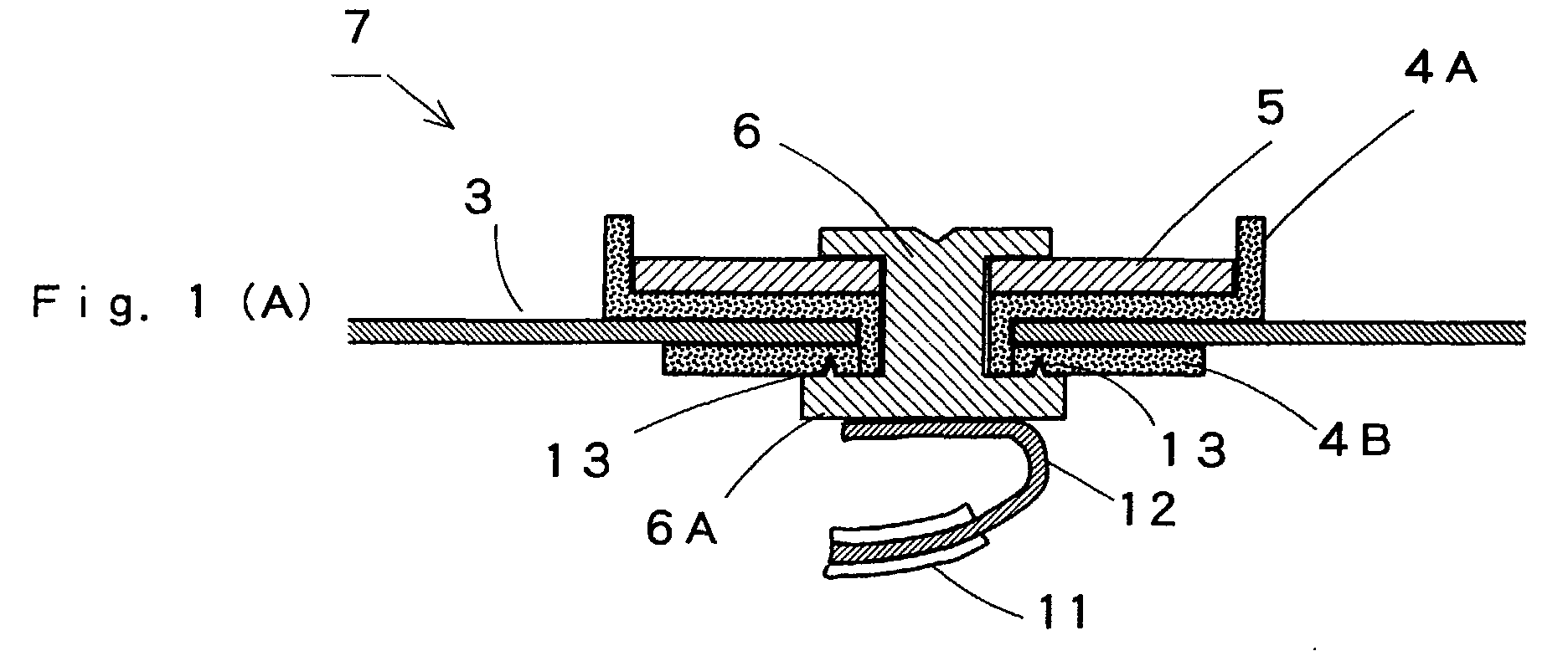
- Figs. 1(A), 1(B) and 1(C) are illustrative of one embodiment of the closed type battery according to the present invention.
- Fig. 2 is illustrative of another embodiment of the closed type battery according to the present invention.
- Figs. 3(A) and 3(B) are illustrative of yet another embodiment of the closed type battery according to the present invention.
- Fig. 4 is illustrative of one example of a conventional closed type battery.
- Figs. 5(A) and 5(B) are illustrative of one example of the header in the closed type battery.
- Fig. 6 is illustrative of another example of the header in the closed type battery.
- Figs. 1(A), 1(B) and 1(C) are illustrative of the closed type battery according to the present invention.
- Fig. 1(B) is illustrative in perspective of parts or members prior to the assembling of a header 7, and Fig. 1(C) is illustrative of one example of an electrode-leading pin.
- a metal plate 3 of the header 7 that forms a part of the closed type battery is provided with an external insulting sheet 4A and an internal insulating sheet 4B that cover the inside surface of a through-hole 10 formed through the metal plate 3 and the upper and lower surface portions of the metal plate 3 around the through-hole, and on top of the external insulating sheet 4A there is provided an electrode-drawing sheet 5.
- the external insulating sheet 4A has a cylindrical shaft 4AT that comes into contact with the internal insulating sheet 4B in a flat sheet form.
- a flange 6A of the electrode-leading pin 6 is provided with a projection 13, so that upon the electrode-heading pin 6 caulked, the projection 13 is engaged into the internal insulating sheet 4B, making it possible to prevent any displacement of the internal insulating sheet 4B.
- the projection 13 is formed on the flange 6A of the electrode-leading pin 6.
- the projection 13 should have an acute tip so that it can be engaged in the surface of contact with the internal insulating sheet. While it is acceptable to form such a projection on a part of the flange, it is preferable to use a ring form of projection because uniform pressure is applied to the internal insulating sheet.
- the projection used should also preferably have a height of 0.05 mm to 0.20 mm.
- Fig. 2 is illustrative in section of another embodiment of the closed type battery according to the present invention, showing in detail the electrode-leading terminal portion of the closed type battery.
- the projection 13 applies strong force to the end of the internal insulating sheet. This may cause the internal insulating sheet 4B to suffer warping as shown at 14, resulting in poor engagement of the flange surface with the internal insulating sheet.
- Such a problem can be solved by use of an electrode-drawing terminal as shown in Fig. 3.
- Figs. 3(A) and 3(B) are illustrative in section of another embodiment of the electrode-drawing terminal of the closed type battery.
- Fig. 3(A) is a sectional view of the electrode-drawing terminal and
- Fig. 3(B) is a sectional view of the electrode-leading pin.
- the electrode-drawing terminal of Fig. 3(A) is characterized in that an electrode-leading pin 6 has a flange 6A provided with a projection 13 and a recess 15.
- the width, W, of the recess 15 should preferably be in the range of 0.05 mm to 0.20 mm and the depth, d, of the recess 15 should preferably be in the range of 0.02 mm to 0.10 mm.
- the projection-and-recess combination has an additional effect on making the length of contact of the electrode-leading pin with the internal insulating sheet so long that much more improved sealability is obtained.
- the recess should preferably be configured in the form of a ring that ensures uniform distribution of pressure.
- the recess should preferably be located nearer to the center of the electrode-leading pin than the projection, and have an acute form that is effective for limiting displacement of the internal insulating sheet.
- the internal and external insulating sheets may be each formed of polypropylene, or thermoplastic fluorocarbon resin such as tetrafluoroethylene-perfluoroalkoxyethylene copolymer (PFA), and tetrafluoroethylene-hexafluoropropylene (FEP), etc.
- PFA tetrafluoroethylene-perfluoroalkoxyethylene copolymer
- FEP tetrafluoroethylene-hexafluoropropylene
- the electrode-drawing sheet provided on the upper surface of the external insulating sheet positioned on the outer surface of the header for instance, use may be of a nickel sheet, a nickeled soft steel sheet, a copper sheet, and a nickel silver sheet.
- the electrode-leading pin it is preferable to use a pin that is obtained by configuring a metal material such as aluminum or its alloy to an electrode-leading pin blank and then annealing that blank.
- Annealing allows the electrode-leading pin to be uniformly transformed upon caulking, and to have so decreased surface hardness that surface cracking or other defects are unlikely to occur. This in turn makes improvements in airtightness between the electrode-leading pin and the insulating member, and so on.
- annealing causes a temporary lowering of the hardness of the electrode-leading pin; however, the electrode-leading pin that has been caulked has a hardness equivalent to that of one not annealed because of being subjected to work-hardening by impacts on caulking.
- the sealing properties are unlikely to become low, nor is the caulking strength of the electrode-leading pin likely to drop.
- External and internal insulating sheets were mounted to a nickeled soft steel plate of oblong shape having a long side of 28.9 mm and a short side of 5.4 mm and provided with a central through-hole of 2.6 mm in diameter.
- an electrode-drawing sheet of a nickel sheet having a central hole of 2.0 mm in diameter was placed on the external insulating sheet.
- the header was welded to a battery can formed of nickeled soft steel and having a height of 47.6 mm, a width of 30.0 mm and a thickness of 5.8 mm, in which a lithium ion battery element was already received. Then, an electrolyte was poured in the battery can through an electrolyte-pouring hole, after which the electrolyte-pouring hole was closed up to make a closed type battery.
- a header was made by caulking an electrode-leading pin from above and below as in Example 1 with the exception that the flange of the electrode-leading pin was provided at a position 1.2 mm away from its center with a tapered, ring recess of 0.5 mm in depth and 0.1 mm in width as measured on the flange surface and at a position outside and adjacent to the recess with a projection of 0.1 mm in height and 0.2 mm in width, thereby obtaining a closed type battery.
- Example 2 With the exception that no projection was formed on the electrode-leading pin, a battery header was prepared as in Example 1, thereby obtaining a closed type battery. The thus assembled 2,000 batteries were measured for whether or not there were electrolyte leakages from their electrode-drawing terminals after the lapse of 8 hours. As a result, it was found that 30 batteries showed electrolyte leakages.
- the external connection terminal is prepared by caulking of the electrode-leading pin via the internal and external insulating sheets.
- This external connection terminal has a projection at the flange surface where the electrode-leading pin comes in contact with the internal insulating sheet. Upon caulking, the internal insulating sheet is unlikely to displace. It is thus possible to provide a closed type battery having improved airtightness.
Landscapes
- Chemical & Material Sciences (AREA)
- Chemical Kinetics & Catalysis (AREA)
- Electrochemistry (AREA)
- General Chemical & Material Sciences (AREA)
- Engineering & Computer Science (AREA)
- Manufacturing & Machinery (AREA)
- Connection Of Batteries Or Terminals (AREA)
- Sealing Battery Cases Or Jackets (AREA)
- Secondary Cells (AREA)
Abstract

Description
The above problems are overcome with a closed-type battery with the features of the claims.
Claims (7)
- A closed type battery having an electrode terminal comprising a metal plate for sealing up an opening in a battery can, an insulating member that cover a through-hole provided through the metal plate and both surfaces of the metal plate around the through-hole, an electrode-drawing sheet positioned on a surface of the insulating member located on an outer surface of a battery and an electrode-leading pin that is inserted into the through-hole in the electrode-drawing sheet and caulked from above and below, wherein:at a surface of contact of a flange of the electrode-leading pin with said insulating member there is provided at least a projection.
- The closed type battery according to claim 1, wherein said flange of said electrode-leading pin is provided with a projection and a recess.
- The closed type battery according to claim 2, wherein said projecting has an acute tip and said recess is acute at a deepest portion.
- The closed type battery according to claim 2 or 3, wherein said recess is located at a position nearer to a center of a shaft of said electrode-leading pin than the projection.
- The battery according to claim 1, 2, 3, or 4, wherein said projection is configured in a ring form.
- The battery according to claim 1, 2, 3, 4, or 5, wherein said flange of said electrode-leading pin is provided with a projection and a recess, each in a ring form.
- The battery according to claim 1, 2, 3, 4, 5, or 6, which is a lithium ion battery.
Applications Claiming Priority (2)
| Application Number | Priority Date | Filing Date | Title |
|---|---|---|---|
| JP2001370325A JP2003173767A (en) | 2001-12-04 | 2001-12-04 | Sealed battery |
| JP2001370325 | 2001-12-04 |
Publications (2)
| Publication Number | Publication Date |
|---|---|
| EP1318554A2 true EP1318554A2 (en) | 2003-06-11 |
| EP1318554A3 EP1318554A3 (en) | 2004-04-07 |
Family
ID=19179565
Family Applications (1)
| Application Number | Title | Priority Date | Filing Date |
|---|---|---|---|
| EP02026941A Withdrawn EP1318554A3 (en) | 2001-12-04 | 2002-12-04 | Sealing structure for a terminal pole in a closed type battery |
Country Status (5)
| Country | Link |
|---|---|
| US (1) | US7029790B2 (en) |
| EP (1) | EP1318554A3 (en) |
| JP (1) | JP2003173767A (en) |
| KR (1) | KR20030045662A (en) |
| TW (1) | TWI239111B (en) |
Cited By (2)
| Publication number | Priority date | Publication date | Assignee | Title |
|---|---|---|---|---|
| DE102013102647A1 (en) | 2013-03-14 | 2014-09-18 | Fele Gmbh & Co. Kg | Connecting bushing for a housing of an electrical component, in particular of a rechargeable battery, and method for mounting a connection feedthrough |
| WO2024020227A1 (en) * | 2022-07-22 | 2024-01-25 | Our Next Energy, Inc. | Cap assembly |
Families Citing this family (30)
| Publication number | Priority date | Publication date | Assignee | Title |
|---|---|---|---|---|
| JP3736789B2 (en) * | 2000-04-10 | 2006-01-18 | Necトーキン栃木株式会社 | Sealed battery |
| US7341802B1 (en) * | 2004-03-25 | 2008-03-11 | Quallion Llc | Feedthrough assembly and method |
| US7807285B1 (en) | 2004-04-07 | 2010-10-05 | Quallion Llc | Battery connection structure and method |
| CN1655389A (en) * | 2005-03-04 | 2005-08-17 | 北京中信国安盟固利新材料技术研究院有限公司 | High capacity lithium ion secondary battery with metal case |
| DE102005045418B3 (en) * | 2005-09-23 | 2006-11-30 | Varta Automotive Systems Gmbh | Accumulator, accumulator block and production process as for hybrid motor vehicle has rectangular housing with connected negative plates spring connected to housing and positives joined to adjacent housing |
| US20080259525A1 (en) * | 2005-11-09 | 2008-10-23 | Maxwell Technologies, Inc. | Energy storage apparatus and article of manufacture |
| JP5170381B2 (en) * | 2007-10-26 | 2013-03-27 | Nok株式会社 | Storage element terminal seal structure |
| JP4508268B2 (en) * | 2008-05-30 | 2010-07-21 | トヨタ自動車株式会社 | Cylindrical battery and manufacturing method thereof |
| JP4756392B2 (en) * | 2008-11-27 | 2011-08-24 | トヨタ自動車株式会社 | battery |
| US8883341B2 (en) | 2009-05-19 | 2014-11-11 | Toyota Jidosha Kabushiki Kaisha | Battery, vehicle mounted with the battery, and device mounted with the battery |
| JP5425526B2 (en) * | 2009-05-29 | 2014-02-26 | 三洋電機株式会社 | Sealed battery |
| KR101084221B1 (en) * | 2009-10-30 | 2011-11-17 | 에스비리모티브 주식회사 | Secondary battery |
| KR101093932B1 (en) * | 2010-01-26 | 2011-12-13 | 에스비리모티브 주식회사 | Secondary battery |
| JP5509111B2 (en) * | 2010-04-20 | 2014-06-04 | 日立ビークルエナジー株式会社 | Secondary battery |
| JP6024095B2 (en) | 2010-12-10 | 2016-11-09 | 株式会社Gsユアサ | Electric storage element, method for manufacturing electric storage element, and method for manufacturing terminal |
| JP6014990B2 (en) | 2010-12-10 | 2016-10-26 | 株式会社Gsユアサ | Battery, current collector, and current collector manufacturing method |
| JP5609610B2 (en) * | 2010-12-10 | 2014-10-22 | 株式会社Gsユアサ | battery |
| TWI450432B (en) * | 2011-03-29 | 2014-08-21 | Ind Tech Res Inst | Battery end cap set |
| JP5987465B2 (en) | 2011-06-17 | 2016-09-07 | 株式会社Gsユアサ | Storage element and method for manufacturing the same |
| KR101265214B1 (en) * | 2011-06-22 | 2013-05-27 | 로베르트 보쉬 게엠베하 | Rechargeable battery and method manufacturing of the same |
| KR101589838B1 (en) * | 2011-06-28 | 2016-01-28 | 쉔젠 비와이디 오토 알앤디 컴퍼니 리미티드 | Electrode terminal, cover assembly and battery comprising the cover assembly |
| US9236596B2 (en) * | 2011-06-30 | 2016-01-12 | Samsung Sdi Co., Ltd. | Rechargeable battery |
| US9570719B2 (en) * | 2013-05-22 | 2017-02-14 | Samsung Sdi Co., Ltd. | Secondary battery |
| JP6127798B2 (en) * | 2013-07-23 | 2017-05-17 | 株式会社豊田自動織機 | Power storage device and manufacturing method thereof |
| EP3062370B1 (en) * | 2013-10-25 | 2019-01-16 | Hitachi Automotive Systems, Ltd. | Rectangular secondary battery |
| JP6428123B2 (en) | 2014-10-06 | 2018-11-28 | 株式会社Gsユアサ | Electricity storage element |
| US10166617B2 (en) | 2016-08-23 | 2019-01-01 | General Electric Company | Electrodes for and methods of electrical discharge machining |
| CA3202317A1 (en) | 2021-01-19 | 2022-07-28 | Lg Energy Solution, Ltd. | Battery and current collector applied thereto, and battery pack and vehicle including the same |
| US12407028B2 (en) * | 2021-02-19 | 2025-09-02 | Lg Energy Solution, Ltd. | Electrode assembly, battery, and battery pack and vehicle including the same |
| JP7617267B2 (en) * | 2021-02-23 | 2025-01-17 | エルジー エナジー ソリューション リミテッド | Secondary battery, battery pack, and automobile |
Family Cites Families (7)
| Publication number | Priority date | Publication date | Assignee | Title |
|---|---|---|---|---|
| CH658547A5 (en) * | 1981-10-20 | 1986-11-14 | Sanyo Electric Co | BATTERY HOUSING. |
| US4859547A (en) | 1987-10-06 | 1989-08-22 | Gates Energy Products, Inc. | Battery terminal and method |
| JPH07245093A (en) | 1994-03-08 | 1995-09-19 | Shin Kobe Electric Mach Co Ltd | Square sealed battery top lid |
| US6579640B1 (en) | 1999-09-28 | 2003-06-17 | Sanyo Electric Co., Ltd. | Sealed rectangular battery and manufacturing method for the same |
| JP3736789B2 (en) * | 2000-04-10 | 2006-01-18 | Necトーキン栃木株式会社 | Sealed battery |
| JP2002075328A (en) * | 2000-09-04 | 2002-03-15 | Japan Storage Battery Co Ltd | Sealed lead-acid battery |
| JP2002151022A (en) * | 2000-11-14 | 2002-05-24 | Wako Denshi Kk | Rechargeable battery lid |
-
2001
- 2001-12-04 JP JP2001370325A patent/JP2003173767A/en active Pending
-
2002
- 2002-12-03 US US10/308,035 patent/US7029790B2/en not_active Expired - Lifetime
- 2002-12-04 EP EP02026941A patent/EP1318554A3/en not_active Withdrawn
- 2002-12-04 KR KR1020020086157A patent/KR20030045662A/en not_active Ceased
- 2002-12-19 TW TW091136692A patent/TWI239111B/en not_active IP Right Cessation
Cited By (2)
| Publication number | Priority date | Publication date | Assignee | Title |
|---|---|---|---|---|
| DE102013102647A1 (en) | 2013-03-14 | 2014-09-18 | Fele Gmbh & Co. Kg | Connecting bushing for a housing of an electrical component, in particular of a rechargeable battery, and method for mounting a connection feedthrough |
| WO2024020227A1 (en) * | 2022-07-22 | 2024-01-25 | Our Next Energy, Inc. | Cap assembly |
Also Published As
| Publication number | Publication date |
|---|---|
| JP2003173767A (en) | 2003-06-20 |
| US7029790B2 (en) | 2006-04-18 |
| US20030104276A1 (en) | 2003-06-05 |
| EP1318554A3 (en) | 2004-04-07 |
| KR20030045662A (en) | 2003-06-11 |
| TW200411964A (en) | 2004-07-01 |
| TWI239111B (en) | 2005-09-01 |
Similar Documents
| Publication | Publication Date | Title |
|---|---|---|
| US7029790B2 (en) | Closed type battery | |
| EP1300893B1 (en) | Closed type battery | |
| US6977125B2 (en) | Closed type battery | |
| US6379839B1 (en) | Battery having welded lead plate | |
| US7781092B2 (en) | Secondary battery and method of manufacturing same | |
| JP5021900B2 (en) | Sealed battery | |
| JP3756097B2 (en) | Sealed battery | |
| US8852797B2 (en) | Lithium ion secondary battery with anti-rotation cap assembly | |
| JPH10340709A (en) | Prismatic battery | |
| JP2004146362A (en) | Cap assembly, secondary battery including the same, and method of manufacturing cap assembly | |
| JP4201301B2 (en) | Sealed battery | |
| US8685561B2 (en) | Rechargeable battery | |
| JP2001185100A (en) | Sealed battery | |
| JP2000231917A (en) | Sealed battery | |
| JP4829432B2 (en) | Sealed battery | |
| WO2018123123A1 (en) | Alkali dry cell | |
| JP2001351608A (en) | Sealed battery | |
| JP4841076B2 (en) | Sealed battery | |
| JP3812380B2 (en) | Sealed battery | |
| JP4932092B2 (en) | Sealed battery | |
| CN114342137B (en) | Rechargeable battery | |
| KR101222228B1 (en) | Lithium rechargeable battery and Method of making the same | |
| JP2003045407A (en) | Sealed battery | |
| JP2005085646A (en) | Sealed battery |
Legal Events
| Date | Code | Title | Description |
|---|---|---|---|
| PUAI | Public reference made under article 153(3) epc to a published international application that has entered the european phase |
Free format text: ORIGINAL CODE: 0009012 |
|
| AK | Designated contracting states |
Designated state(s): AT BE BG CH CY CZ DE DK EE ES FI FR GB GR IE IT LI LU MC NL PT SE SI SK TR |
|
| AX | Request for extension of the european patent |
Extension state: AL LT LV MK RO |
|
| PUAL | Search report despatched |
Free format text: ORIGINAL CODE: 0009013 |
|
| AK | Designated contracting states |
Kind code of ref document: A3 Designated state(s): AT BE BG CH CY CZ DE DK EE ES FI FR GB GR IE IT LI LU MC NL PT SE SI SK TR |
|
| AX | Request for extension of the european patent |
Extension state: AL LT LV MK RO |
|
| 17P | Request for examination filed |
Effective date: 20040629 |
|
| AKX | Designation fees paid |
Designated state(s): DE FR |
|
| STAA | Information on the status of an ep patent application or granted ep patent |
Free format text: STATUS: THE APPLICATION HAS BEEN WITHDRAWN |
|
| 18W | Application withdrawn |
Effective date: 20090525 |