EP1318503A2 - Audio signal outputting method, audio signal reproduction method, and computer program product - Google Patents
Audio signal outputting method, audio signal reproduction method, and computer program product Download PDFInfo
- Publication number
- EP1318503A2 EP1318503A2 EP02257013A EP02257013A EP1318503A2 EP 1318503 A2 EP1318503 A2 EP 1318503A2 EP 02257013 A EP02257013 A EP 02257013A EP 02257013 A EP02257013 A EP 02257013A EP 1318503 A2 EP1318503 A2 EP 1318503A2
- Authority
- EP
- European Patent Office
- Prior art keywords
- audio signal
- event
- musical
- timing
- occurrence
- Prior art date
- Legal status (The legal status is an assumption and is not a legal conclusion. Google has not performed a legal analysis and makes no representation as to the accuracy of the status listed.)
- Withdrawn
Links
Images

Classifications
-
- G—PHYSICS
- G11—INFORMATION STORAGE
- G11B—INFORMATION STORAGE BASED ON RELATIVE MOVEMENT BETWEEN RECORD CARRIER AND TRANSDUCER
- G11B20/00—Signal processing not specific to the method of recording or reproducing; Circuits therefor
- G11B20/10—Digital recording or reproducing
-
- G—PHYSICS
- G10—MUSICAL INSTRUMENTS; ACOUSTICS
- G10H—ELECTROPHONIC MUSICAL INSTRUMENTS; INSTRUMENTS IN WHICH THE TONES ARE GENERATED BY ELECTROMECHANICAL MEANS OR ELECTRONIC GENERATORS, OR IN WHICH THE TONES ARE SYNTHESISED FROM A DATA STORE
- G10H1/00—Details of electrophonic musical instruments
- G10H1/0033—Recording/reproducing or transmission of music for electrophonic musical instruments
- G10H1/0041—Recording/reproducing or transmission of music for electrophonic musical instruments in coded form
- G10H1/0058—Transmission between separate instruments or between individual components of a musical system
- G10H1/0066—Transmission between separate instruments or between individual components of a musical system using a MIDI interface
-
- G—PHYSICS
- G10—MUSICAL INSTRUMENTS; ACOUSTICS
- G10H—ELECTROPHONIC MUSICAL INSTRUMENTS; INSTRUMENTS IN WHICH THE TONES ARE GENERATED BY ELECTROMECHANICAL MEANS OR ELECTRONIC GENERATORS, OR IN WHICH THE TONES ARE SYNTHESISED FROM A DATA STORE
- G10H2210/00—Aspects or methods of musical processing having intrinsic musical character, i.e. involving musical theory or musical parameters or relying on musical knowledge, as applied in electrophonic musical tools or instruments
- G10H2210/021—Background music, e.g. for video sequences or elevator music
- G10H2210/026—Background music, e.g. for video sequences or elevator music for games, e.g. videogames
Definitions
- the present invention relates to an audio signal outputting technology for the BGM (background music), sound effects, etc. used in a game.
- the main program which performs the primary game processing; the digital audio signals for reproducing BGM, sound effects, etc.; the control program for controlling the operation of the audio processor; etc, are recorded in an optical disk medium which stores the game software.
- the game apparatus reads the game software from the optical disk medium, develops it in the main memory, and performs game processing in response to keyed input operations of the player. In this game processing, the orchestration of acoustic effects is accomplished by outputring BGM, sound effects, etc. at the appropriate timing.
- the method of outputting BGM in a game is, for example, to switch the outputted BGM matched to game timing, such as when the game scene changes, when an enemy character is shot down, or when the player's game character gets a power boost, etc.
- a methods is used whereby the BGM is faded out, its output volume gradually being lowered, while the BGM to be newly reproduced is faded in, its output volume gradually being increased.
- BGM switching with good timing from a musical standpoint cannot be done.
- a game scene changes in the middle of a musical bar of the BGM being reproduced
- BGM switching through fading in or fading out hinders a continuous musical linking and can cause the player to feel some strangeness.
- it is not easy to prepare a plurality of BGM pieces matched to game scenes so in general a procedure is adopted whereby a few BGM pieces are used repeatedly in each game scene.
- an object of the present invention is to provide a technology which outputs an audio signal that has no unnatural feeling whenever an audio signal, reproduced and outputted, is switched. This is done by switching at a timing that is musically appropriate.
- a subject of the invention is to provide technology for rich musical expression, by combining data streams. This is done by turning on and off, according to the game scene, some of the plurality of data streams which make up a single BGM piece.
- the audio signal outputting method of the present invention captures the progress (timing) of the musical piece for each of a plurality of data streams, which are mutually synchronized musically.
- the method selects, from among above-mentioned plurality of data streams, a data stream combination corresponding to that event, doing so at a timing where there is a musical break, and reproduces and outputs the audio signal.
- the audio signal is changed at a musically appropriate timing.
- a computer-readable recording medium a program for causing a computer system to execute the above-mentioned audio signal outputting method.
- recording medium there are portable recording media, such as optical recording media (recording media from which data may be read optically, such as CD-RAM, CD-ROM, DVD-RAM, DVD-ROM, DVD-R, PD disk, MD disk, MO disk, etc.); magnetic recording media (recording media from which data may be read magnetically, such as flexible disk, magnetic card, magnetic tape, etc.); memory cartridges having memory elements (semiconductor memory elements such as DRAM's, and high dielectric memory elements, such as FRAM's).
- the above-mentioned program can be delivered "on-demand" from a network server, such as a Web server and the like, in response to a request from a client device (a personal computer, a game machine, or a portable terminal such as a portable telephone, a personal digital assistance (PDA), or a Palm-type PC, with a Web browser incorporated) connected to an open network, such as the Internet, a packet communication network, or the like.
- a client device a personal computer, a game machine, or a portable terminal such as a portable telephone, a personal digital assistance (PDA), or a Palm-type PC, with a Web browser incorporated
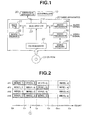
- Fig. 1 is a block diagram of a game apparatus.
- game apparatus 20 is a computer system comprising main CPU 21, work memory 22, bus arbiter 23, audio processor 24, video processor 25, video memory 26, and CD-ROM drive 27.
- Main CPU 21 reads game software supplied from CD-ROM 28 via CD-ROM drive 27 and develops it in work memory 22. Then, based on various operation signals outputted from controller 10 via bus arbiter 23, game processing is performed, and the appearance formed in virtual space is converted to an image viewed from the chosen viewpoint and plotting commands are issued to the video processor 25. Following those plotting commands, video processor 25 performs rendering of the polygons and, by means of double buffering, writes the graphic data for the next frame into video memory 26. At the same time, it reads out graphic data for the current frame, performs a D/A conversion, and generates a video signal.
- MIDI Musical Instrument Digital Interface
- MIDI messages for outputting BGM are stored in CD-ROM 28.
- Each of these MIDI messages includes messages such as Note On, Note Off, Polyphonic Key Pressure, Control Change, Program Change, Channel Pressure, and Pitch Bend Change, as well as channel voice messages formed from additional data, such as key number, controller number, program number, pressure value, variable amount (course), velocity, and pressure.
- Main CPU 21 reads the MIDI messages of all channels, develops them in work memory 22, and for each data stream, captures (tracks) the reproduction timing by counting the clock tick number which finely divides into a specified number the beat that regulates the reproduction timing of the BGM.
- Fig. 2 is an explanatory diagram of the MIDI messages for reproducing BGM.
- each channel is a MIDI message for a different melody: channel 1 expresses melody 1, channel 2 expresses melody 2, channel 3 expresses melody 3, and channel 4 expresses melody 4.
- the MIDI message for each channel is configured of MIDI data for each bar.
- the MIDI message of channel 1 is comprised of MIDI [01], MIDI [02], MIDI [03], ..., MIDI [On].
- MIDI [n-1, m] indicates the MIDI data for the m th bar of channel n.
- the first clock tick number of the first bar is indicated by c 0
- the first clock tick number of the second bar is indicated by c 1
- the first clock tick number or the n th bar is indicated by c n-1 .
- main CPU 21 selects MIDI data to be actually reproduced and outputted and transmits it to audio processor 24.
- the MIDI data transmitted from main CPU 21 to audio processor 24 is MIDI data which has 1 bar as its basic unit. In the figure, two channels of MIDI data are transmitted.
- Audio processor 24 is equipped with a MIDI sound source and reproduces an audio signal for line-out output from the MIDI data of MIDI [i-1, k] and MIDI [j-1, k] transmitted from main CPU 21.
- a vibration table is provided in CD-ROM 28.
- This vibration table is one in which vibration waveforms for causing vibration apparatus 30 to vibrate are recorded.
- the vibration table includes four waveform patterns: vb1, vb2, vb3, and vb4.
- Main CPU 21 reads the vibration table from CD-ROM 28 and develops it in work memory 22. Further, as will be explained later, when a specified event occur, the CPU reads the waveform data corresponding to that event and outputs it to vibration apparatus 30 via bus arbiter 23.
- Vibration apparatus 30 incorporates a drive motor having an eccentric weight attached to its drive shaft for causing vibration and, driving the vibration motor based on waveform data supplied from main CPU 21, it outputs vibration corresponding to the waveform pattern.
- This vibration apparatus 30 is a portable vibration generating apparatus and is used by the player by holding it between his thighs, under his arm in his palm, for example. As explained later, because it vibrates in response to the occurrence of an event, it can give the player a stimulus of the appropriate level, enabling him to enjoy the game more.
- Fig. 4 is an event table which shows muting operators allocated according to the types of events and the correspondence relationship of the vibration patterns.
- the muting operator is an operator for producing a logical calculation in the muting table to change the BGM reproduced and outputted from audio processor 24.
- Fig. 5 in the muting table, for each MIDI message of the four channels, "1" is for "active” and "0” is for "inactive.” In the same figure, because the muting table shows "1001," channel 1 and channel 4 are active.
- Main CPU 21 referring to the muting table, transmits to audio processor 24 the MIDI data which has been made active.
- audio processor 24 reproduces and outputs MIDI [0,1] and MIDI [3/1] for the period when clock tick number is from c 0 to c 1 and reproduces and outputs MIDI [0,2] and MIDI [3,2] for the period when clock tick number is from c 1 to c 2 .
- main CPU 21 sets the event flag to "1". Then, in the stare where the event flag is set to "1", when the clock tick number which the counter is counting reaches c 2 , main CPU 21, referring to the event table, changes the MIDI message and vibration pattern which are active.
- the corresponding muting operator is "1100” and the vibration pattern is "vb2”, so main CPU 21 performs a logical calculation on "1001” in the muting table and changes the muting table value.
- the CPU also outputs the waveform data of vibration pattern "vb2" to vibration apparatus 30.
- the issue of how to set the muting operator is completely at the user's discretion, and it can be set to change the BGM corresponding to various events which occur as the game is developed. For example, when the game is progressing in a way favorable to the player, a major key may be used, while when game progress is not to the advantage of the player, a minor key is used, and, in the case of a good thing happening to the player, bright chords can be used more. Likewise, when the game progress has become monotonous, few chord changes are made, while in the case of fast-paced player activity, the tempo may be speeded up. In cases where the game has settled down, the tempo can be slowed, while for scenes where complex operations are required of the player, complicated musical pieces can be used.
- Bright melodies are selected for cases where the player's game character transitions to a bright stage, while when he moves to a dark stage, solemn melodies may be selected.
- a melody can be selected which gives a feeling of tension, while when he breaks out from being surrounded by those enemy characters, a cheerful melody is selected.
- the degree of applying echo or other effects may be increased, while when the player's game character goes out into an open place, the degree of applying echo or other effects can be reduced.
- the muting operator can be set to change the tempo, key, chords, rhythm pattern, and so on matched to the movements of the player's game character, such as when he gets up, changes the direction of his movement, jumps, receives damage, gains an "item," uses the item, makes a violent movement, moves slowly, rolls along, makes tiny movements, makes grand movements, falls down, or when an enemy character brandishes his sword, or when the player corners on a road course, etc.
- MIDI messages may be allocated to each channel such that of the 64 channels, channel 1 through channel 16 are melodies for use by the player's game character, channel 17 through channel 32 are rhythms for use by the player's game character, channel 33 through channel 48 are melodies for use by enemy characters, and channels 49 through 64 are rhythms for use by enemy characters.
- each kind of vibration pattern can be set according to the game situation, etc. at the time an event occurs.
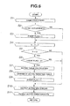
- FIG. 6 is a flow chart indicating those steps.
- Main CPU 21 performs the processing steps indicated in that flow chart each 1/60 th of a second, which is the graphic updating period.
- Main CPU 21 responsive to the player's input operations, performs the specified game processing (S1) and checks whether there has been an event occurrence (S2). If an event occurrence is detected (S2: YES), the event flag is set to "1" (S3), while if an event occurrence is not detected (S2: NO). the event flag remains "0", and the value of the clock tick number, c, which the counter counts is increased by 1 (S4).
- main CPU 21 outputs the active MIDI data to audio processor 24 (S10) and, in addition, the active vibration data is outputted to vibration apparatus 30 (S11).
- the above-mentioned processing steps S10 and S11 are performed.
- BGM is not changed abruptly upon occurrence of an event, but, by changing the BGM output based on divisions with 1 musical bar as a unit, a BGM output method can be achieved with no sense of musical unnaturalness.
- the vibration pattern of vibration apparatus 30 can be changed in synchronization with the BGM change, so that a set rhythm for the acoustic changes and the vibration changes can be achieved.
- the audio signal outputting method of the present invention can be applied not only co BGM outputting methods, but also to outputting methods for various kinds of audio signals.
- the data stream for reproducing audio signals need not be limited to MIDI data, but may be any desired sound data such as WAV data, AIFF data, MP3 data, RAW data, WMA data, etc.
Landscapes
- Engineering & Computer Science (AREA)
- Physics & Mathematics (AREA)
- Acoustics & Sound (AREA)
- Multimedia (AREA)
- Signal Processing (AREA)
- Electrophonic Musical Instruments (AREA)
Abstract
Description

Claims (14)
- An audio signal outputting method comprising the steps of:capturing the musical piece progress timing for each of a plurality of data streams, mutually synchronized musically;detecting the occurrence of an event which changes the audio signal to be reproduced and outputted; andupon detection of said event occurrence, reproducing and outputting an audio signal by selecting from said plurality of data streams a combination of data streams corresponding to said event, at a timing where there is a musical break.
- An audio signal outputting method comprising the steps of:capturing the musical piece progress timing for each MIDI message of multiple channels, mutually synchronized musically;detecting the occurrence of an event which changes the audio signal to be reproduced and outputted; andupon detection of said event occurrence, reproducing and outputting an audio signal by selecting from said plurality of MIDI messages a combination of MIDI messages corresponding to said event, at a timing where there is a musical break.
- The audio signal outputting method according to claim 1, wherein said timing where there is a musical break involves at least either a break of musical bars or a break in the rhythm, following said event occurrence.
- The audio signal outputting method according to claim 1, wherein said audio signal is the sound effects in a game.
- The audio signal outputting method according to claim 1, wherein said event is an event which causes change in the progress of the game.
- The audio signal outputting method according to claim 1, wherein waveform data for driving a vibration apparatus is changed at a timing where there is a musical break.
- A computer program product in which a program for causing a computer system to execute game processing is recorded on a computer-readable recording medium, wherein said computer program causes execution of the steps of:capturing the musical piece progress timing for each of a plurality of data streams, mutually synchronized musically;detecting the occurrence of an event which changes the audio signal to be reproduced and outputted; andupon detection of said event occurrence reproducing and outputting an audio signal by selecting from said plurality of data streams a combination of data streams corresponding to said event, at a timing where there is a musical break.
- A computer program product in which a program for causing a computer system to execute game processing is recorded on a computer-readable recording medium, wherein said computer program causes execution of the steps of:capturing the musical piece progress timing for each MIDI message of multiple channels, mutually synchronized musically;detecting the occurrence of an event which changes the audio signal to be reproduced and outputted; andupon detection of said event occurrence, reproducing and outputting an audio signal by selecting from said plurality of MIDI messages a combination of MIDI messages corresponding to said event, at a timing where there is a musical break.
- The computer program product according to claim 7, wherein said timing where there is a musical break involves at least either a break of musical bars or a break in the rhythm, following said event occurrence.
- The computer program product according to claim 7, wherein said audio signal is the sound effects in a game.
- The computer program product according to claim 7, wherein said event is an event which causes change in the progress of the game.
- The computer program product according to claim 7, wherein the computer program also causes execution of the step of changing waveform data for driving a vibration apparatus at a timing where there is a musical break.
- An audio signal outputting apparatus comprising:means for capturing the musical piece progress timing of each of a plurality of data streams, mutually synchronized musically;means for detecting the occurrence of an event which changes the audio signal to be reproduced and outputted; andmeans for reproducing and outputting an acoustic signal by selecting from said plurality of data streams a combination of data streams corresponding to said event upon detection of said event occurrence, at a timing where there is a musical break.
- An audio signal outputting method, comprising the steps of:outputting data representing musical audio comprising a regular succession of musical time units detecting the occurrence of an audio-changing event; andin response to the detection of said event occurrence, changing the audio signal output from said data representing musical audio to a different audio signal at a timing corresponding to the end of the musical time unit during which the occurrence event was detected.
Applications Claiming Priority (2)
| Application Number | Priority Date | Filing Date | Title |
|---|---|---|---|
| JP2001314598A JP2003122358A (en) | 2001-10-11 | 2001-10-11 | Acoustic signal output method, acoustic signal generation apparatus, and program |
| JP2001314598 | 2001-10-11 |
Publications (2)
| Publication Number | Publication Date |
|---|---|
| EP1318503A2 true EP1318503A2 (en) | 2003-06-11 |
| EP1318503A3 EP1318503A3 (en) | 2004-02-04 |
Family
ID=19132883
Family Applications (1)
| Application Number | Title | Priority Date | Filing Date |
|---|---|---|---|
| EP02257013A Withdrawn EP1318503A3 (en) | 2001-10-11 | 2002-10-09 | Audio signal reproduction method |
Country Status (4)
| Country | Link |
|---|---|
| US (1) | US6828498B2 (en) |
| EP (1) | EP1318503A3 (en) |
| JP (1) | JP2003122358A (en) |
| KR (1) | KR20030030866A (en) |
Families Citing this family (17)
| Publication number | Priority date | Publication date | Assignee | Title |
|---|---|---|---|---|
| US8008561B2 (en) * | 2003-01-17 | 2011-08-30 | Motorola Mobility, Inc. | Audio file format with mapped lighting effects and method for controlling lighting effects using an audio file format |
| US8841847B2 (en) | 2003-01-17 | 2014-09-23 | Motorola Mobility Llc | Electronic device for controlling lighting effects using an audio file |
| JP2005227628A (en) * | 2004-02-13 | 2005-08-25 | Matsushita Electric Ind Co Ltd | Control system, method and program using rhythm pattern |
| US8115091B2 (en) * | 2004-07-16 | 2012-02-14 | Motorola Mobility, Inc. | Method and device for controlling vibrational and light effects using instrument definitions in an audio file format |
| KR20100069736A (en) * | 2008-12-17 | 2010-06-25 | 삼성전자주식회사 | Contents play device of portable device and method thereof |
| GB2474680B (en) * | 2009-10-22 | 2012-01-18 | Sony Comp Entertainment Europe | Audio processing method and apparatus |
| FR2974226A1 (en) * | 2011-04-12 | 2012-10-19 | Mxp4 | METHOD FOR GENERATING SOUND EFFECT IN GAME SOFTWARE, ASSOCIATED COMPUTER PROGRAM, AND COMPUTER SYSTEM FOR EXECUTING COMPUTER PROGRAM INSTRUCTIONS. |
| JP2013046661A (en) * | 2011-08-29 | 2013-03-07 | Square Enix Co Ltd | Music switching device in game machine |
| JP6357387B2 (en) | 2014-08-26 | 2018-07-11 | 任天堂株式会社 | Information processing apparatus, information processing system, information processing program, and information processing method |
| JP2016045848A (en) | 2014-08-26 | 2016-04-04 | 任天堂株式会社 | Information processing apparatus, information processing system, information processing program, and information processing method |
| JP6441612B2 (en) * | 2014-08-26 | 2018-12-19 | 任天堂株式会社 | Information processing apparatus, information processing system, information processing program, and information processing method |
| JP6540119B2 (en) * | 2015-03-16 | 2019-07-10 | ヤマハ株式会社 | Effector, method and program |
| JP2017131409A (en) * | 2016-01-28 | 2017-08-03 | 株式会社カプコン | Game program and game system |
| US10453434B1 (en) | 2017-05-16 | 2019-10-22 | John William Byrd | System for synthesizing sounds from prototypes |
| JP6598266B1 (en) * | 2018-10-11 | 2019-10-30 | 株式会社コナミアミューズメント | GAME SYSTEM AND GAME PROGRAM |
| JPWO2021049181A1 (en) * | 2019-09-10 | 2021-03-18 | ||
| US12425207B2 (en) * | 2023-12-27 | 2025-09-23 | United States Of America, As Represented By The Secretary Of The Navy | Musical instrument digital interface encryption and compression |
Family Cites Families (11)
| Publication number | Priority date | Publication date | Assignee | Title |
|---|---|---|---|---|
| US4087792A (en) * | 1977-03-03 | 1978-05-02 | Westinghouse Electric Corp. | Electro-optic display system |
| JP2568659B2 (en) * | 1988-12-12 | 1997-01-08 | 松下電器産業株式会社 | Driving method of display device |
| JP2743680B2 (en) * | 1992-01-16 | 1998-04-22 | ヤマハ株式会社 | Automatic performance device |
| IT1282613B1 (en) * | 1996-02-13 | 1998-03-31 | Roland Europ Spa | ELECTRONIC EQUIPMENT FOR THE COMPOSITION AND AUTOMATIC REPRODUCTION OF MUSICAL DATA |
| US5890017A (en) * | 1996-11-20 | 1999-03-30 | International Business Machines Corporation | Application-independent audio stream mixer |
| US5811706A (en) * | 1997-05-27 | 1998-09-22 | Rockwell Semiconductor Systems, Inc. | Synthesizer system utilizing mass storage devices for real time, low latency access of musical instrument digital samples |
| US6464585B1 (en) * | 1997-11-20 | 2002-10-15 | Nintendo Co., Ltd. | Sound generating device and video game device using the same |
| US6093880A (en) * | 1998-05-26 | 2000-07-25 | Oz Interactive, Inc. | System for prioritizing audio for a virtual environment |
| US5902947A (en) * | 1998-09-16 | 1999-05-11 | Microsoft Corporation | System and method for arranging and invoking music event processors |
| DE60019526T2 (en) * | 1999-10-14 | 2006-02-23 | Sony Computer Entertainment Inc. | Entertainment system |
| IT1316734B1 (en) * | 2000-07-07 | 2003-05-12 | Korg Italy S P A | ELECTRONIC DEVICE MAKING MORE SEQUECERS CAPABLE OF DEFENDING IN AN INDEPENDENT OR COORDINATED MANNER |
-
2001
- 2001-10-11 JP JP2001314598A patent/JP2003122358A/en active Pending
-
2002
- 2002-10-01 KR KR1020020059669A patent/KR20030030866A/en not_active Withdrawn
- 2002-10-09 EP EP02257013A patent/EP1318503A3/en not_active Withdrawn
- 2002-10-10 US US10/267,832 patent/US6828498B2/en not_active Expired - Lifetime
Also Published As
| Publication number | Publication date |
|---|---|
| KR20030030866A (en) | 2003-04-18 |
| EP1318503A3 (en) | 2004-02-04 |
| US20030070538A1 (en) | 2003-04-17 |
| US6828498B2 (en) | 2004-12-07 |
| JP2003122358A (en) | 2003-04-25 |
Similar Documents
| Publication | Publication Date | Title |
|---|---|---|
| US6828498B2 (en) | Audio signal outputting method, audio signal reproduction method, and computer program product | |
| JP3149574B2 (en) | Karaoke equipment | |
| JP2895932B2 (en) | Animation synthesis display device | |
| JP3686906B2 (en) | Music game program and music game apparatus | |
| JP2983292B2 (en) | Virtual musical instrument, control unit for use with virtual musical instrument, and method of operating virtual musical instrument | |
| US5915972A (en) | Display apparatus for karaoke | |
| JP3322275B2 (en) | Karaoke equipment | |
| JP5241805B2 (en) | Timing offset tolerance karaoke game | |
| JP3324158B2 (en) | Karaoke equipment | |
| KR20020062598A (en) | Audio signal outputting method and bgm gerneration method | |
| JP2947032B2 (en) | Karaoke equipment | |
| JP2000107455A (en) | Game device and information storage medium | |
| JP3942720B2 (en) | Musical sound generating device, image generating device, game device, and information storage medium | |
| JP3062784B2 (en) | Music player | |
| JP4270102B2 (en) | Automatic performance device and program | |
| JPH06124062A (en) | Karaoke machine | |
| JPH08234775A (en) | Music reproducing device | |
| JP4648707B2 (en) | Program, information storage medium, and game system | |
| JP3928725B2 (en) | Music signal generator and legato processing program | |
| JP3067538B2 (en) | Character string display color change signal generation device and character string display device | |
| JP2007175513A (en) | GAME DEVICE AND INFORMATION STORAGE MEDIUM | |
| JP4161714B2 (en) | Karaoke equipment | |
| JP3511237B2 (en) | Karaoke equipment | |
| JPH08123448A (en) | Image processing device using waveform analysis of audio signal | |
| JP3622315B2 (en) | Karaoke display device |
Legal Events
| Date | Code | Title | Description |
|---|---|---|---|
| PUAI | Public reference made under article 153(3) epc to a published international application that has entered the european phase |
Free format text: ORIGINAL CODE: 0009012 |
|
| AK | Designated contracting states |
Designated state(s): AT BE BG CH CY CZ DE DK EE ES FI FR GB GR IE IT LI LU MC NL PT SE SK TR |
|
| AX | Request for extension of the european patent |
Extension state: AL LT LV MK RO SI |
|
| RTI1 | Title (correction) |
Free format text: AUDIO SIGNAL REPRODUCTION METHOD |
|
| PUAL | Search report despatched |
Free format text: ORIGINAL CODE: 0009013 |
|
| AK | Designated contracting states |
Kind code of ref document: A3 Designated state(s): AT BE BG CH CY CZ DE DK EE ES FI FR GB GR IE IT LI LU MC NL PT SE SK TR |
|
| AX | Request for extension of the european patent |
Extension state: AL LT LV MK RO SI |
|
| 17P | Request for examination filed |
Effective date: 20040602 |
|
| AKX | Designation fees paid |
Designated state(s): DE ES FR GB IT |
|
| 17Q | First examination report despatched |
Effective date: 20061016 |
|
| STAA | Information on the status of an ep patent application or granted ep patent |
Free format text: STATUS: THE APPLICATION IS DEEMED TO BE WITHDRAWN |
|
| 18D | Application deemed to be withdrawn |
Effective date: 20090501 |