EP1318414A2 - Flugzeug- oder satellitengestütztes tomographisches Radarverfahren mit synthetischer Apertur (SAR) - Google Patents
Flugzeug- oder satellitengestütztes tomographisches Radarverfahren mit synthetischer Apertur (SAR) Download PDFInfo
- Publication number
- EP1318414A2 EP1318414A2 EP02027103A EP02027103A EP1318414A2 EP 1318414 A2 EP1318414 A2 EP 1318414A2 EP 02027103 A EP02027103 A EP 02027103A EP 02027103 A EP02027103 A EP 02027103A EP 1318414 A2 EP1318414 A2 EP 1318414A2
- Authority
- EP
- European Patent Office
- Prior art keywords
- sar
- radar
- satellite
- radar method
- satellites
- Prior art date
- Legal status (The legal status is an assumption and is not a legal conclusion. Google has not performed a legal analysis and makes no representation as to the accuracy of the status listed.)
- Ceased
Links
Images






Classifications
-
- G—PHYSICS
- G01—MEASURING; TESTING
- G01S—RADIO DIRECTION-FINDING; RADIO NAVIGATION; DETERMINING DISTANCE OR VELOCITY BY USE OF RADIO WAVES; LOCATING OR PRESENCE-DETECTING BY USE OF THE REFLECTION OR RERADIATION OF RADIO WAVES; ANALOGOUS ARRANGEMENTS USING OTHER WAVES
- G01S13/00—Systems using the reflection or reradiation of radio waves, e.g. radar systems; Analogous systems using reflection or reradiation of waves whose nature or wavelength is irrelevant or unspecified
- G01S13/88—Radar or analogous systems specially adapted for specific applications
- G01S13/89—Radar or analogous systems specially adapted for specific applications for mapping or imaging
- G01S13/90—Radar or analogous systems specially adapted for specific applications for mapping or imaging using synthetic aperture techniques, e.g. synthetic aperture radar [SAR] techniques
- G01S13/904—SAR modes
-
- G—PHYSICS
- G01—MEASURING; TESTING
- G01S—RADIO DIRECTION-FINDING; RADIO NAVIGATION; DETERMINING DISTANCE OR VELOCITY BY USE OF RADIO WAVES; LOCATING OR PRESENCE-DETECTING BY USE OF THE REFLECTION OR RERADIATION OF RADIO WAVES; ANALOGOUS ARRANGEMENTS USING OTHER WAVES
- G01S13/00—Systems using the reflection or reradiation of radio waves, e.g. radar systems; Analogous systems using reflection or reradiation of waves whose nature or wavelength is irrelevant or unspecified
- G01S13/88—Radar or analogous systems specially adapted for specific applications
- G01S13/89—Radar or analogous systems specially adapted for specific applications for mapping or imaging
- G01S13/90—Radar or analogous systems specially adapted for specific applications for mapping or imaging using synthetic aperture techniques, e.g. synthetic aperture radar [SAR] techniques
- G01S13/904—SAR modes
- G01S13/9043—Forward-looking SAR
-
- G—PHYSICS
- G01—MEASURING; TESTING
- G01S—RADIO DIRECTION-FINDING; RADIO NAVIGATION; DETERMINING DISTANCE OR VELOCITY BY USE OF RADIO WAVES; LOCATING OR PRESENCE-DETECTING BY USE OF THE REFLECTION OR RERADIATION OF RADIO WAVES; ANALOGOUS ARRANGEMENTS USING OTHER WAVES
- G01S13/00—Systems using the reflection or reradiation of radio waves, e.g. radar systems; Analogous systems using reflection or reradiation of waves whose nature or wavelength is irrelevant or unspecified
- G01S13/88—Radar or analogous systems specially adapted for specific applications
- G01S13/89—Radar or analogous systems specially adapted for specific applications for mapping or imaging
- G01S13/90—Radar or analogous systems specially adapted for specific applications for mapping or imaging using synthetic aperture techniques, e.g. synthetic aperture radar [SAR] techniques
- G01S13/904—SAR modes
- G01S13/9058—Bistatic or multistatic SAR
Definitions
- the invention relates to an aircraft or satellite-based Radar sensor working, tomographic radar method with synthetic aperture (SAR) for three-dimensional Object mapping, with a coherent combination of one larger number of SAR sensor recordings from different A three-dimensional image and the backscatter contributions from volume targets in the Height can be analyzed separately and independently of one another.
- SAR synthetic aperture
- Imaging radar methods work with an active radar sensor, by means of radiation and reception of electromagnetic Waves in the microwave range a reflectivity map of the illuminated area.
- SAR Synthetic Aperture Radar
- SAR Synthetic Aperture Radar
- a known imaging SAR radar method is the so-called SAR interferometry (INSAR), which is in the article by R.Bamler and P.Hartl: “Synthetic Aperture Radar Interferometry ", Inverse Problems, Vol. 14, pages R1-R54, 1998 is described and understood as a technology is where the phase difference between two of easy different positions recorded SAR images evaluated becomes. This phase difference depends on the one that has occurred Elevation angle and thus together with the terrain topography. This enables the creation of highly accurate digital elevation models (DEMs; Digital Elevation Models) INSAR images, the height of each image element medium scattering center is decisive.
- DEMs Digital Elevation Models
- the SAR interferometry method has in particular the disadvantage that only the height of a medium Scattering center can be measured. With this procedure not a real three-dimensional image, but instead only the averaged topographic height of all in a resolution element occurring spreader determined. In the case of volume targets the various spreading contributions appear still overlaid.
- the INSAR procedure is out of this Reason not suitable for a detailed analysis of volume targets. On top of that, INSAR measurements are not entirely ambiguous, and it's another processing step namely the so-called »phase unwrapping «, necessary to this Eliminate ambiguities.
- Model-based approaches based on polarimetric or multi-frequency interferograms are principally based on few simple parameters when analyzing volume targets limited. Your area of application is therefore very limited. Moreover they are strongly dependent on the validity of the used Scattering model dependent and fail completely if the hit Assumptions are wrong.
- a separation of the backscatter contributions in height can be also by radar pulses sent vertically downwards, as in the article by M. Hallikainen, J. Hyyp Georg, J. Haapanen, T. Tares, P. Ahola, J. Pulliainen, M. Toikka: "A helicopter-borne eight-channel ranging scatterometer for remote sensing - Part 1: System description ", IEEE Trans. on Geoscience and Remote Sensing, Vol. 31, No. 1, pages 161-169, 1993. Unlike the two before explained, known methods is the height resolution achieved here by measuring the time of flight of the radar.
- Lidar Light Detection and Ranging sensors
- microwave pulses here are short ones
- Laser pulses are sent vertically downwards, again a precise runtime measurement enables a height resolution.
- a lidar has small gaps in the Depends on forest to penetrate to the ground and is therefore strongly dependent on the forest type. Cloudiness also prevents that Use of a lidar system. Generally you can with one Lidar only measure the height of vegetation; to a three-dimensional Volume analysis it can not be used.
- the invention is based on the object in a three-dimensional imaging SAR radar system performing a separate analysis of the superimposed backscatter contributions, combined with a precise determination of the associated elevation angle without too much technical and time expenditure to enable what a number of applications of great would be meaning.
- An exact and ambiguous determination of the topographic height the elevation angle of the backscatter would also have applications in the three-dimensional image and Mapping of buildings, urban areas and mountainous areas open.
- this task solved that the different viewing directions through a set of independently working and simultaneously operated SAR antennas are formed.
- known multi-pass tomography at different angles through repeated parallel overflights will be implemented instead at inventive method a set of independent SAR antennas operated simultaneously.
- inventive procedures will be those for multi-pass tomography applicable disadvantages eliminated.
- the method according to the invention offers a number of advantages. It becomes a clear determination of the origin of all Scatter contributions allow, regardless of assumptions about the depicted objects.
- the method according to the invention offers a true three-dimensional image of the study area. The entire data recording is done with a single flyover. The operational effort is thus greatly reduced. An uneven distribution of the trajectories and the associated low image quality are avoided. A temporal decorrelation during the Data recording is avoided.
- the radar sensor is usually used in the method according to the invention operated in the side view direction.
- a variant of the method according to the invention is one such sensor not in side view, but instead in To operate forward gaze direction. This way even with a small antenna group a high resolution in of height.
- the long synthetic aperture that results from the forward movement of the sensor leads in the forward gaze direction to a very high resolution in elevation and therefore in height.
- a high range resolution results from the runtime measurement of the radar itself. Perpendicular to the direction of movement of the sensor in the horizontal There is a level of resolution corresponding to the level Length of the real aperture of the antenna group perpendicular to Flight direction.
- Another variant of the method according to the invention is the operation looking down.
- generated the long synthetic aperture in flight direction one high resolution in azimuth; the height resolution results from the time-of-flight measurement of the radar.
- Perpendicular to the direction of movement of the sensor is in turn determined by the real aperture of the Antenna group in this direction has a higher resolution won.
- a variant of the method according to the invention is the extension the so-called "Cartwheel” concept by D. Massonet (WO 99/58997) for a larger number of satellites Execution of a three-dimensional object mapping. With a sufficiently extensive distribution of the Receiver satellites can also be used over long distances achieve a high quality image.
- FIG. 1 shows the basic geometry of a radar sensor in a Cartesian xyz coordinate system in a side view for three-dimensional object imaging.
- the sensor moves in parallel along the x-axis.
- the various independent antenna elements of an antenna group are arranged in such a way that each (path 1, 2,..., N -1, N of the antenna elements) has a different perspective on the scene and thus on volume targets V.
- FIG 2 shows a simplified geometry in which an antenna group consisting of antenna elements is the aperture length L and the distances between the antenna elements d and in which the mean angle of incidence is 0 degrees, ie the n-axis from FIG Direction is.
- the distance between a spreader at height n 0 and the antenna element with the position z is the distance between a spreader at height n 0 and the antenna element with the position z
- An approach similar to that of the SPECAN process is available for processing. Multiplying this signal by a so-called "deramping" function u ( z ) the result is a signal whose wavenumber in the z direction no longer depends on z , but only on the height of the spreader n 0 :
- an L-band system would fly at an altitude of 500m and a total extension of the antenna group of 30m in show a resolution of 3m.
- the distance d between the individual antenna elements must also be noted.
- the condition is that the signal spectrum generated by a volume of height H is sufficiently sampled d ⁇ ⁇ r 0 2 H observed. Otherwise there are strong ambiguities within the volume examined.
- the resolutions at distance and along the flight direction are identical to a conventional SAR sensor and are c ⁇ / 2 and L az / 2, respectively, where c denotes the speed of light, ⁇ the pulse duration and L az the length of the antenna in the flight direction.
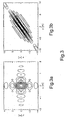
- 3a and 3b show in the x - y representation and in the y - z representation simulated impulse responses of a tomographic radar sensor operating according to the invention in a side view.
- ⁇ y Due to the limited extent of the antenna group and the distance dependency of the resolution, ⁇ y is relatively low for common system parameters. Nevertheless, an acceptable resolution can be achieved with a relatively low flight height even with a small size of the antenna group. For example, an antenna group with a total length of 5m at a distance of 1000m shows a resolution of 25m.
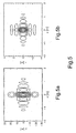
- FIG. 4a and 4b show in the x - y representation and in the x - z representation simulated impulse responses of a tomographic radar sensor working according to the invention in a forward view.
- 5a and 5b show, in the x - y representation and in the x - z representation, simulated impulse responses of a tomographic radar sensor working according to the invention with a view downward.
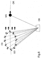
- Fig.8 and Fig.9 are two different options for a working according to the method of the invention Expansion of the satellite-based "Cartwheel” concept shown.
- This concept is followed by a number of receiver satellites ES a sending master satellite MS, where the receiver satellites ES from the object OB after irradiation signals backscattered by the master satellite MS receive.
- the receiver satellites ES and MS By an appropriate setting of the Satellites ES and MS to traversing orbits OR it is possible that the receiver satellites ES stable and in even distances on an ellipse E0 behind the Move master satellites MS.
- By arranging a larger one Number of receiver satellites ES in one or more "Cartwheels" parallel to one another behind the Master satellites MS can take multiple angles on that Realize object. Move in the embodiment of Fig.9 the receiver satellites on two "Cartwheel” ellipses E1 and E2 ES behind the master satellite MS.
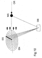
- Fig.10 is another possibility for a corresponding extension of the method according to the invention satellite-based "Cartwheel” concept shown.
- Here runs on each of several parallel to each other in a plane "Cartwheel” ellipses EN only one receiver satellite IT around.
- the receiver satellites ES are on the whole a common beam of all ellipses E0 and follow the master satellite on orbit OR.
- a "cartwheel” system works from a side view.
- the resolving power the height is therefore described by equation (6).
- the aperture length L is the diameter of the entire arrangement.
- a "cartwheel" system in the L band at an altitude of 500km for a height resolution of 3m need a diameter of about 30km.
- At a Arrangement as in Fig. 10 would require 10 satellites to to reproduce a volume with a thickness of 30m without ambiguity.
Landscapes
- Engineering & Computer Science (AREA)
- Remote Sensing (AREA)
- Radar, Positioning & Navigation (AREA)
- Physics & Mathematics (AREA)
- Electromagnetism (AREA)
- Computer Networks & Wireless Communication (AREA)
- General Physics & Mathematics (AREA)
- Radar Systems Or Details Thereof (AREA)
Abstract
Description


- E1, E2
- Ellipsen
- EN
- Ellipsen
- E0
- Ellipse
- ES
- Empfängersatellit
- MS
- Mastersatellit
- OB
- Objekt
- OR
- Orbit
- V
- Volumenziel
Claims (9)
- Mit einem flugzeug- oder satellitengestützten Radarsensor arbeitendes, tomographisches Radarverfahren mit synthetischer Apertur (SAR) zur dreidimensionalen Objektabbildung, wobei durch kohärente Kombination einer größeren Anzahl von SAR-Sensoraufnahmen aus unterschiedlichen Blickrichtungen eine echte dreidimensionale Abbildung gewonnen wird und die Rückstreubeiträge von Volumenzielen in der Höhe getrennt und unabhängig voneinander analysiert werden, dadurch gekennzeichnet, daß die unterschiedlichen Blickrichtungen durch einen Satz von voneinander unabhängig arbeitenden und simultan betriebenen SAR-Antennen gebildet werden.
- Radarverfahren nach Anspruch 1, dadurch gekennzeichnet, daß im Falle flugzeuggestützter Radarsensoren die unterschiedlichen Blickrichtungen durch einzelne simultan betriebene und physikalisch zueinander in fester Relation stehende SAR-Antennenelemente einer am Flugzeug fest angebrachten Antennengruppe gebildet werden.
- Radarverfahren nach Anspruch 1, dadurch gekennzeichnet, daß im Falle satellitengestützter Radarsensoren die unterschiedlichen Blickrichtungen durch einzelne simultan betriebene SAR-Antennen von Empfängern auf physikalisch getrennten Satelliten einer sich gemeinsam und gleichförmig bewegenden Satellitengruppe gebildet werden, wobei von einem Master-Satellit aus gesendet wird.
- Radarverfahren nach Anspruch 3, dadurch gekennzeichnet, daß auf einem Orbit (OR) eine Anzahl von Empfängersatelliten (ES) einem sendenden Mastersatelliten (MS) folgt und daß der Orbit der Satelliten so eingestellt ist, daß sich die Empfängersatelliten stabil auf einer Ellipse (E0) oder auf mehreren in einer Ebene zueinander parallelen Ellipsen (E1, E2, EN) hinter dem Mastersatelliten gleichsinnig bewegen.
- Radarverfahren nach Anspruch 4, dadurch gekennzeichnet, daß mehrere jeweils auf einer Ellipse (E0, E1, E2) gleichsinnig umlaufende Empfängersatelliten (ES) sich mit gleichen gegenseitigen Abständen bewegen.
- Radarverfahren nach Anspruch 4, dadurch gekennzeichnet, daß auf jeder von mehreren in einer Ebene parallelen Ellipsen (EN) jeweils ein Empfängersatellit (ES) umläuft und daß die Empfängersatelliten auf einem gemeinsamen Brennpunktstrahl aller Ellipsen liegen.
- Radarverfahren nach einem der vorhergehenden Ansprüche, dadurch gekennzeichnet, daß die Radarsensoren in Seitensichtrichtung betrieben werden.
- Radarverfahren nach einem der Ansprüche 1 bis 2, dadurch gekennzeichnet, daß die Radarsensoren in Vorwärtssichtrichtung betrieben werden.
- Radarverfahren nach einem der Ansprüche 1 bis 2, dadurch gekennzeichnet, daß die Radarsensoren in Sichtrichtung nach unten betrieben werden.
Applications Claiming Priority (2)
| Application Number | Priority Date | Filing Date | Title |
|---|---|---|---|
| DE10160399A DE10160399B4 (de) | 2001-12-10 | 2001-12-10 | Flugzeug- oder satellitengestütztes tomographisches Radarverfahren mit synthetischer Apertur |
| DE10160399 | 2001-12-10 |
Publications (2)
| Publication Number | Publication Date |
|---|---|
| EP1318414A2 true EP1318414A2 (de) | 2003-06-11 |
| EP1318414A3 EP1318414A3 (de) | 2003-09-17 |
Family
ID=7708544
Family Applications (1)
| Application Number | Title | Priority Date | Filing Date |
|---|---|---|---|
| EP02027103A Ceased EP1318414A3 (de) | 2001-12-10 | 2002-12-04 | Flugzeug- oder satellitengestütztes tomographisches Radarverfahren mit synthetischer Apertur (SAR) |
Country Status (3)
| Country | Link |
|---|---|
| US (1) | US6894637B2 (de) |
| EP (1) | EP1318414A3 (de) |
| DE (1) | DE10160399B4 (de) |
Cited By (5)
| Publication number | Priority date | Publication date | Assignee | Title |
|---|---|---|---|---|
| CN104199032A (zh) * | 2014-08-29 | 2014-12-10 | 中国科学院电子学研究所 | 一种基于相关系数的层析sar成像的航迹分布优化方法 |
| US9400329B2 (en) | 2014-01-20 | 2016-07-26 | Venkateshwara PILLAY | System for mapping and tracking ground targets |
| CN108983229A (zh) * | 2018-05-03 | 2018-12-11 | 电子科技大学 | 基于sar层析技术的高压输电铁塔高度及形变提取方法 |
| CN116990813A (zh) * | 2023-06-16 | 2023-11-03 | 北京理工大学 | 基于空间变换的非均匀基线层析sar原子范数三维成像 |
| CN118330641A (zh) * | 2024-06-14 | 2024-07-12 | 中国电子科技集团公司第十四研究所 | 一种编队卫星大视角协同乒乓sar模式的实现方法及设备 |
Families Citing this family (30)
| Publication number | Priority date | Publication date | Assignee | Title |
|---|---|---|---|---|
| US6879279B2 (en) * | 2003-01-14 | 2005-04-12 | The Regents Of The University Of California | Differential optical synthetic aperture radar |
| US7633427B2 (en) * | 2005-10-20 | 2009-12-15 | Kinetx, Inc. | Active imaging using satellite communication system |
| US7924210B2 (en) * | 2006-06-02 | 2011-04-12 | Zimmerman Associates, Inc. | System, method, and apparatus for remote measurement of terrestrial biomass |
| US7511655B2 (en) * | 2006-09-25 | 2009-03-31 | The United States Of America As Represented By The Secretary Of The Navy | Method and apparatus for 3-D sub-voxel position imaging with synthetic aperture radar |
| ITPI20070012A1 (it) * | 2007-02-14 | 2008-08-15 | Univ Pisa | Metodo di elaborazione di dati radar multipassaggio per il rilevamento e l'analisi di componenti multiple di retrodiffusori non stazionari |
| DE102007015561B3 (de) * | 2007-03-29 | 2008-08-21 | Deutsches Zentrum für Luft- und Raumfahrt e.V. | Verfahren zum Untersuchen eines Eisgebiets oder trockenen Gebiets mittels Radar-Echolot-Sondierung |
| US8125370B1 (en) | 2007-04-16 | 2012-02-28 | The United States Of America As Represented By The Secretary Of The Navy | Polarimetric synthetic aperture radar signature detector |
| US7548192B1 (en) * | 2008-02-07 | 2009-06-16 | Fdh Engineering, Inc. | Method of mapping steel reinforcements in concrete foundations |
| US8040273B2 (en) * | 2009-07-14 | 2011-10-18 | Raytheon Company | Radar for imaging of buildings |
| US8581772B2 (en) * | 2010-06-04 | 2013-11-12 | Brigham Young University | Method, apparatus, and system to remotely acquire information from volumes in a snowpack |
| KR101009967B1 (ko) | 2010-08-12 | 2011-01-20 | 엘아이지넥스원 주식회사 | 레이더 영상 생성 장치와 그 방법, 및 상기 방법을 구현하는 프로그램이 기록된 기록매체 |
| CN102004250B (zh) * | 2010-10-28 | 2012-08-08 | 电子科技大学 | 基于频域展开的星机联合双基地合成孔径雷达成像方法 |
| ITTO20110526A1 (it) * | 2011-06-15 | 2012-12-16 | Thales Alenia Space Italia S P A C On Unico Socio | Acquisizione di immagini sar per calcolare una quota o un modello digitale di elevazione tramite elaborazioni interferometriche |
| FR2977683B1 (fr) * | 2011-07-06 | 2016-01-15 | Claude Chekroun | Dispositif pour detecter des objets tels que des mines |
| US8884807B1 (en) * | 2012-05-09 | 2014-11-11 | Malå Geoscience USA | Pseudo real time receive signal sampling for ground penetrating radar |
| US20190004122A1 (en) * | 2014-04-25 | 2019-01-03 | Purdue Research Foundation | Wireless position sensing using magnetic field of single transmitter |
| GB201604415D0 (en) * | 2016-03-15 | 2016-04-27 | Elson Space Engineering Ese Ltd And Ordnance Survey Ltd | Image capturing arrangement |
| IT201600127152A1 (it) * | 2016-12-15 | 2018-06-15 | Ids Georadar S R L | Metodo e apparecchiatura per il monitoraggio di deformazioni superficiali di uno scenario |
| CN108375769B (zh) * | 2017-09-21 | 2022-03-04 | 重庆测威科技有限公司 | 一种结合sar成像和isar成像的雷达成像方法 |
| US10705204B2 (en) | 2017-12-08 | 2020-07-07 | International Business Machines Corporation | Crop classification and growth tracking with synthetic aperture radar |
| WO2020002863A1 (en) * | 2018-06-29 | 2020-01-02 | The Secretary Of State For Defence | Method and apparatus for radar imaging |
| EP4020013B1 (de) * | 2019-08-23 | 2024-08-14 | Spacety Co., Ltd (Changsha) | Fernerkundungssystem basierend auf einem satellitenanordnungs- und -konstellationssystem |
| CN111679277B (zh) * | 2020-05-28 | 2022-05-03 | 电子科技大学 | 一种基于sbrim算法的多基线层析sar三维成像方法 |
| CN112034458B (zh) * | 2020-08-03 | 2022-02-08 | 北京理工大学 | 针对稀疏非均匀基线的层析sar双频解模糊方法 |
| CN112731398B (zh) * | 2021-01-11 | 2024-04-09 | 北京空间飞行器总体设计部 | 一种多维信息探测sar卫星探测方法 |
| CN115166741B (zh) * | 2022-09-08 | 2022-11-29 | 中国科学院空天信息创新研究院 | 一种基于简化模型的双相位中心极化层析分解方法 |
| CN115294133B (zh) * | 2022-10-09 | 2022-12-30 | 中国电子科技集团公司第十四研究所 | 基于高低频极化干涉sar的植被高程反演方法及设备 |
| CN115754924B (zh) * | 2022-11-18 | 2023-05-16 | 北京卫星信息工程研究所 | 卫星分布式短波雷达系统及空间目标探测方法 |
| CN116243311B (zh) * | 2023-01-10 | 2025-11-28 | 上海航天电子通讯设备研究所 | 基于dsp的电子侦察引导星载sar成像方法 |
| CN118089611B (zh) * | 2024-04-17 | 2024-08-30 | 东南大学 | 一种融合InSAR数据和物理知识的建筑三向位移监测方法及系统 |
Family Cites Families (8)
| Publication number | Priority date | Publication date | Assignee | Title |
|---|---|---|---|---|
| DE3430888A1 (de) * | 1984-08-22 | 1986-03-06 | Messerschmitt-Bölkow-Blohm GmbH, 8012 Ottobrunn | Einrichtung zur detektion und bekaempfung untergezogener bodenziele |
| US5332999A (en) * | 1993-02-05 | 1994-07-26 | Agence Spatiale Europeenne | Process for generating synthetic aperture radar interferograms |
| US5463397A (en) * | 1993-10-25 | 1995-10-31 | Hughes Aircraft Company | Hyper-precision SAR interferometry using a dual-antenna multi-pass SAR system |
| US5677693A (en) * | 1994-05-26 | 1997-10-14 | Hughes Aircraft Company | Multi-pass and multi-channel interferometric synthetic aperture radars |
| US6011505A (en) * | 1996-07-11 | 2000-01-04 | Science Applications International Corporation | Terrain elevation measurement by interferometric synthetic aperture radar (IFSAR) |
| FR2778747B1 (fr) * | 1998-05-13 | 2000-08-04 | Centre Nat Etd Spatiales | Dispositif d'interferometrie radar utilisant des satellites |
| US6011625A (en) * | 1998-07-08 | 2000-01-04 | Lockheed Martin Corporation | Method for phase unwrapping in imaging systems |
| DE19938592C2 (de) * | 1999-08-18 | 2003-02-27 | Deutsch Zentr Luft & Raumfahrt | Flugzeug- oder weltraumflugkörpergetragenes Radarsystem mit synthetischer Antennenapertur |
-
2001
- 2001-12-10 DE DE10160399A patent/DE10160399B4/de not_active Expired - Lifetime
-
2002
- 2002-12-04 EP EP02027103A patent/EP1318414A3/de not_active Ceased
- 2002-12-09 US US10/314,629 patent/US6894637B2/en not_active Expired - Lifetime
Cited By (6)
| Publication number | Priority date | Publication date | Assignee | Title |
|---|---|---|---|---|
| US9400329B2 (en) | 2014-01-20 | 2016-07-26 | Venkateshwara PILLAY | System for mapping and tracking ground targets |
| CN104199032A (zh) * | 2014-08-29 | 2014-12-10 | 中国科学院电子学研究所 | 一种基于相关系数的层析sar成像的航迹分布优化方法 |
| CN104199032B (zh) * | 2014-08-29 | 2017-01-11 | 中国科学院电子学研究所 | 一种基于相关系数的层析sar成像的航迹分布优化方法 |
| CN108983229A (zh) * | 2018-05-03 | 2018-12-11 | 电子科技大学 | 基于sar层析技术的高压输电铁塔高度及形变提取方法 |
| CN116990813A (zh) * | 2023-06-16 | 2023-11-03 | 北京理工大学 | 基于空间变换的非均匀基线层析sar原子范数三维成像 |
| CN118330641A (zh) * | 2024-06-14 | 2024-07-12 | 中国电子科技集团公司第十四研究所 | 一种编队卫星大视角协同乒乓sar模式的实现方法及设备 |
Also Published As
| Publication number | Publication date |
|---|---|
| US20030122700A1 (en) | 2003-07-03 |
| US6894637B2 (en) | 2005-05-17 |
| DE10160399B4 (de) | 2004-05-27 |
| DE10160399A1 (de) | 2003-06-26 |
| EP1318414A3 (de) | 2003-09-17 |
Similar Documents
| Publication | Publication Date | Title |
|---|---|---|
| DE10160399B4 (de) | Flugzeug- oder satellitengestütztes tomographisches Radarverfahren mit synthetischer Apertur | |
| EP2130062B1 (de) | Verfahren zum untersuchen eines eisgebiets oder trockenen gebiets mittels radar-echolot-sondierung | |
| EP3803454B1 (de) | Synthetik-apertur-radarverfahren und synthetik-apertur-radarvorrichtung | |
| EP0286806B1 (de) | Verfahren zur topografischen Kartierung | |
| DE69924011T2 (de) | Sar-radarsystem | |
| EP0795762B1 (de) | Verfahren zur Azimut-Skalierung von SAR-Daten und hochgenauer Prozessor zur zweidimensionalen Verarbeitung von ScanSAR-Daten | |
| Banda et al. | Single and multipolarimetric P-band SAR tomography of subsurface ice structure | |
| DE4037156C2 (de) | Vorrichtung und Verfahren zur Bestimmung der Radarrückstreuquerschnitte von Radarzielen | |
| DE102005062031A1 (de) | Hochauflösende Synthetik-Apertur-Radarvorrichtung und Antenne für eine hochauflösende Synthetik-Apertur-Radarvorrichtung | |
| DE69630816T2 (de) | Doppler-radarhöhenmesser mit kompensierter verzögerung | |
| Guliaev et al. | On the use of tomographically derived reflectivity profiles for pol-InSAR forest height inversion in the context of the BIOMASS mission | |
| EP1515159A1 (de) | Verfahren zur Verringerung des Dopplerzentroids bei einem kohärenten Impuls-Radarsystem | |
| DE102023113349B4 (de) | Verfahren zum Bestimmen einer vertikalen Struktur eines halbtransparenten Mediums aus SAR-Daten eines SAR-Systems | |
| DE102018105431A1 (de) | Radarsystem und Verfahren zur Messung horizontal aufgelöster Windfelder in der Mesosphäre und/oder unteren Thermosphäre | |
| DE102005023787A1 (de) | Verfahren und Vorrichtung zum Korrigieren von Wetterdaten sowie Computerprogrammprodukt | |
| Bekaert et al. | Multichannel surface clutter suppression: East Antarctica P-band SAR ice sounding in the presence of grating lobes | |
| DE102016224962B3 (de) | Synthetik-Apertur-Radarverfahren und Synthetik-Apertur-Radarsystem | |
| DE102022133858B4 (de) | Verfahren zur rechnergestützten Verarbeitung von SAR-Rohdaten | |
| Lee | Forest parameter estimation using polarimetric SAR interferometry techniques at low frequencies | |
| DE102024103164B3 (de) | Verfahren und System zur Verarbeitung von SAR-Rohdaten, die von einem SAR-System erfasst wurden | |
| EP2829892B1 (de) | Verfahren zur rechnergestützten Verarbeitung von SAR-Daten | |
| Schirinzi | Forest SAR Tomography: Principles and Applications | |
| DE102022117088A1 (de) | Verfahren zur Erkennung und Auflösung von Phasenmehrdeutigkeiten in interferometrischen SAR-Daten | |
| WO2025232938A1 (de) | Verfahren zur ermittlung der position von oberflächennah im boden befindlichen zielobjekten | |
| DE102023118273A1 (de) | Radar-basierte Ortung oberflächennaher Objekte |
Legal Events
| Date | Code | Title | Description |
|---|---|---|---|
| PUAI | Public reference made under article 153(3) epc to a published international application that has entered the european phase |
Free format text: ORIGINAL CODE: 0009012 |
|
| AK | Designated contracting states |
Designated state(s): AT BE BG CH CY CZ DE DK EE ES FI FR GB GR IE IT LI LU MC NL PT SE SI SK TR |
|
| AX | Request for extension of the european patent |
Extension state: AL LT LV MK RO |
|
| PUAL | Search report despatched |
Free format text: ORIGINAL CODE: 0009013 |
|
| AK | Designated contracting states |
Kind code of ref document: A3 Designated state(s): AT BE BG CH CY CZ DE DK EE ES FI FR GB GR IE IT LI LU MC NL PT SE SI SK TR |
|
| AX | Request for extension of the european patent |
Extension state: AL LT LV MK RO |
|
| 17P | Request for examination filed |
Effective date: 20040303 |
|
| 17Q | First examination report despatched |
Effective date: 20040426 |
|
| AKX | Designation fees paid |
Designated state(s): DE FR GB IT |
|
| STAA | Information on the status of an ep patent application or granted ep patent |
Free format text: STATUS: THE APPLICATION HAS BEEN REFUSED |
|
| 18R | Application refused |
Effective date: 20050913 |