EP1318364A2 - System and method for defrost termination feedback - Google Patents
System and method for defrost termination feedback Download PDFInfo
- Publication number
- EP1318364A2 EP1318364A2 EP02258206A EP02258206A EP1318364A2 EP 1318364 A2 EP1318364 A2 EP 1318364A2 EP 02258206 A EP02258206 A EP 02258206A EP 02258206 A EP02258206 A EP 02258206A EP 1318364 A2 EP1318364 A2 EP 1318364A2
- Authority
- EP
- European Patent Office
- Prior art keywords
- thermostat
- high voltage
- outdoor
- voltage line
- reversing valve
- Prior art date
- Legal status (The legal status is an assumption and is not a legal conclusion. Google has not performed a legal analysis and makes no representation as to the accuracy of the status listed.)
- Granted
Links
Images




Classifications
-
- F—MECHANICAL ENGINEERING; LIGHTING; HEATING; WEAPONS; BLASTING
- F25—REFRIGERATION OR COOLING; COMBINED HEATING AND REFRIGERATION SYSTEMS; HEAT PUMP SYSTEMS; MANUFACTURE OR STORAGE OF ICE; LIQUEFACTION SOLIDIFICATION OF GASES
- F25B—REFRIGERATION MACHINES, PLANTS OR SYSTEMS; COMBINED HEATING AND REFRIGERATION SYSTEMS; HEAT PUMP SYSTEMS
- F25B30/00—Heat pumps
-
- F—MECHANICAL ENGINEERING; LIGHTING; HEATING; WEAPONS; BLASTING
- F25—REFRIGERATION OR COOLING; COMBINED HEATING AND REFRIGERATION SYSTEMS; HEAT PUMP SYSTEMS; MANUFACTURE OR STORAGE OF ICE; LIQUEFACTION SOLIDIFICATION OF GASES
- F25B—REFRIGERATION MACHINES, PLANTS OR SYSTEMS; COMBINED HEATING AND REFRIGERATION SYSTEMS; HEAT PUMP SYSTEMS
- F25B47/00—Arrangements for preventing or removing deposits or corrosion, not provided for in another subclass
- F25B47/02—Defrosting cycles
- F25B47/022—Defrosting cycles hot gas defrosting
- F25B47/025—Defrosting cycles hot gas defrosting by reversing the cycle
-
- F—MECHANICAL ENGINEERING; LIGHTING; HEATING; WEAPONS; BLASTING
- F25—REFRIGERATION OR COOLING; COMBINED HEATING AND REFRIGERATION SYSTEMS; HEAT PUMP SYSTEMS; MANUFACTURE OR STORAGE OF ICE; LIQUEFACTION SOLIDIFICATION OF GASES
- F25B—REFRIGERATION MACHINES, PLANTS OR SYSTEMS; COMBINED HEATING AND REFRIGERATION SYSTEMS; HEAT PUMP SYSTEMS
- F25B13/00—Compression machines, plants or systems, with reversible cycle
-
- F—MECHANICAL ENGINEERING; LIGHTING; HEATING; WEAPONS; BLASTING
- F25—REFRIGERATION OR COOLING; COMBINED HEATING AND REFRIGERATION SYSTEMS; HEAT PUMP SYSTEMS; MANUFACTURE OR STORAGE OF ICE; LIQUEFACTION SOLIDIFICATION OF GASES
- F25B—REFRIGERATION MACHINES, PLANTS OR SYSTEMS; COMBINED HEATING AND REFRIGERATION SYSTEMS; HEAT PUMP SYSTEMS
- F25B2313/00—Compression machines, plants or systems with reversible cycle not otherwise provided for
- F25B2313/031—Sensor arrangements
- F25B2313/0315—Temperature sensors near the outdoor heat exchanger
Definitions
- This invention relates generally to the field of heat pumps, and more particularly to a fixed-speed duct-free split heat pump unit.
- Heat pump systems use a refrigerant to carry thermal energy between a relatively hotter side of a circulation loop to a relatively cooler side of the circulation loop. Compression of the refrigerant occurs at the hotter side of the loop, where a compressor raises the temperature of the refrigerant. Evaporation of the refrigerant occurs at the cooler side of the loop, where the refrigerant is allowed to expand, thus resulting in a temperature drop. Thermal energy is added to the refrigerant on one side of the loop and extracted from the refrigerant on the other side, due to the temperature differences between the refrigerant and the indoor and outdoor mediums, respectively, to make use of the outdoor mediums as either a thermal energy source or a thermal energy sink. In the case of an air to water heat pump, outdoor air is used as a thermal energy source while water is used as a thermal energy sink.
- the process is reversible, so the heat pump can be used for either heating or cooling.
- Residential heating and cooling units are bidirectional, in that suitable valve and control arrangements selectively direct the refrigerant through indoor and outdoor heat exchangers so that the indoor heat exchanger is on the hot side of the refrigerant circulation loop for heating and on the cool side for cooling.
- a circulation fan passes indoor air over the indoor heat exchanger and through ducts leading to the indoor space. Return ducts extract air from the indoor space and bring the air back to the indoor heat exchanger.
- a fan likewise passes ambient air over the outdoor heat exchanger, and releases heat into the open air, or extracts available heat therefrom.
- heat pump systems operate only if there is an adequate temperature difference between the refrigerant and the air at the respective heat exchanger to maintain a transfer of thermal energy.
- the heat pump system is efficient provided the temperature difference between the air and the refrigerant is such that the available thermal energy is greater than the electrical energy needed to operate the compressor and the respective fans.
- the temperature difference between the air and the refrigerant generally is sufficient, even on hot days.
- frost builds up on a coil of the heat pump.
- the speed of the frost build-up is strongly dependent on the ambient temperature and the humidity ratio.
- Coil frosting results in lower coil efficiency while affecting the overall performance (heating capacity and coefficient of performance (COP)) of the unit.
- the coil From time to time, the coil must be defrosted to improve the unit efficiency. In most cases, coil defrosting is achieved through refrigerant cycle inversion. The time during which the coil defrosting occurs impacts the overall efficiency of the unit, since the hot refrigerant in the unit, which provides the desired heat, is actually cooled during coil defrosting.
- the defrost operation which eliminates the frost accumulated on the outdoor heat exchanger during heating operation requires feedback from the outdoor unit to the indoor unit to terminate the defrost operation.
- a low voltage sensor 10 is needed for the outdoor heat exchanger temperature detection. This requires two low voltage lines of interconnection wires 14, 16 to connect sensor 10 to an indoor electronic control 12.
- a system which uses an outdoor sensorless defrost algorithm includes a current transformer 22 on indoor electronic control 12 to measure current flows through a compressor 24 to detect the defrost termination point.
- a magnetic contactor 26 is used to turn compressor 24 on and off. There is then a need for an additional high voltage interconnection wire 28 to make the compressor current flow through the current transformer loop on indoor electronic control 12.
- a heat pump system includes an indoor unit and an outdoor unit, with a compressor, an outdoor fan, and a reversing valve all in the outdoor unit.
- a thermostat is added to the outdoor unit with one side of the thermostat connected to a high voltage line for either a compressor or a magnetic contactor and the other side connected to a high voltage line for either an outdoor fan or a reversing valve.
- a signal collection circuit in the indoor unit is connected to a high voltage line for the outdoor fan when the other side of the thermostat is connected to the outdoor fan and to a high voltage line for the reversing valve when the other side of the thermostat is connected to the reversing valve.
- the thermostat sends a signal to the electronic control board when the defrosting operation should be terminated.
- a heat pump system includes an indoor unit and an outdoor unit, along with a compressor, an outdoor fan, and a reversing valve all in the outdoor unit; a thermostat in the outdoor unit; a first side of the thermostat connected to a high voltage line for one of a compressor and a magnetic contactor and a second side of the thermostat connected to a high voltage line for one of an outdoor fan and a reversing valve; and a signal collection circuit in the indoor unit connected to a high voltage line for the outdoor fan when the second side of the thermostat is connected to the outdoor fan and to a high voltage line for the reversing valve when the second side of the thermostat is connected to the reversing valve.
- a method for terminating a defrost operation in a heat pump system having an indoor unit and an outdoor unit includes the steps of connecting, in the outdoor unit, a first side of a thermostat between a high voltage line for one of a compressor and a magnetic contactor and connecting a second side of the thermostat to a high voltage line for one of an outdoor fan and a reversing valve; connecting, in the indoor unit, a signal collection circuit to a high voltage line for the outdoor fan when the second side of the thermostat is connected to the outdoor fan, and to a high voltage line for the reversing valve when the second side of the thermostat is connected to the reversing valve; and terminating the defrost operation when the thermostat is activated upon reaching a predetermined temperature.
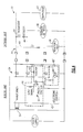
- a heat pump system 30 includes an outdoor unit 32 and an indoor unit 34.
- the initiation of the defrost operation is decided by a temperature delta calculation equation based on conventional inputs.
- a reversing valve 36 changes it status to OFF, an outdoor fan 38 turns OFF, and a compressor 40 is running.
- the outdoor coil then becomes warmer so that the frost accumulated on the outdoor coil is melted and drained away.
- the outdoor coil temperature is too hot after the frost is completely melted, causing the over load protector (OLP) of compressor 40 to become activated to cut off the power to the compressor motor.
- OLP over load protector
- the present invention prevents the activation of the OLP of compressor 40 by using a thermostat to signal an indoor electronic control 42 to cut off the power to compressor 40 when the thermostat indicates an outdoor coil temperature of a predetermined temperature, preferably between 15 to 40 degrees C.
- a relay K1 controls compressor 40, a relay K2 controls outdoor fan 38, and relay K3 controls reversing valve 36.
- a transformer 54 is a step down transformer for the low voltage power supply for indoor electronic control 42.
- a high voltage thermostat 44 and a resistor 46 in outdoor unit 32 are connected in series between the high voltage lines for compressor 40 and outdoor fan 38, or alternately between the high voltage lines for compressor 40 and reversing valve 36 as shown by a connection 49.
- Thermostat 44 detects the temperature at the outdoor heat exchanger.
- the signal from thermostat 44 is then received from the high voltage line for outdoor fan 38 by a signal collection circuit 48, or alternately from the high voltage line for reversing valve 36 by a signal collection circuit 48'.
- Signal collection circuit 48 preferably includes a resistor 50 connecting a photo-coupler 52 to the high voltage line for outdoor fan 38.
- An input signal is derived from photo-coupler 52, which signal is an input to indoor electronic control 42.
- Photo-coupler 52 converts the signal from a high voltage signal to a low voltage signal.
- Signal collection circuit 48' which is the same as signal collection circuit 48, is used instead of signal collection circuit 48 when thermostat 44 is connected using connection 49.
- Signal collection circuit 48' therefore connects to the high voltage line for reversing valve 36 instead of to the high voltage line for outdoor fan 38.
- Resistors 46 and 50 are preferably 30 K resistors rated at 5 W. Since the value of resistor 46 is several tens of kilo-ohms, compressor 40 and outdoor fan 38 cannot be run even though power is supplied to compressor 40 and outdoor fan 38 through this resistor 46.
- a heat pump system 30' is shown which is similar to the prior art system of Fig. 3.
- signal collection circuit 48 is used.
- signal collection circuit 48' is used.
- the defrost operation begins in step 60.
- outdoor fan 38 is turned off via relay K2 in step 62, while reversing valve 36 is turned off in step 64, i.e., reversing valve 36 is in the cooling position, typically accomplished by turning relay K3 off.
- step 66 only compressor 40 is running, i.e., relay K1 is ON. While compressor 40 is running, thermostat 44 is activated according to the temperature changes of the outdoor heat exchanger. If the input signal is not received from thermostat 44 in step 68, the compressor remains on in step 66. When the input signal is received from thermostat 44, i.e., thermostat 44 is activated, this activation is transferred as the input signal to indoor electronic control 42 as explained above. Indoor electronic control 42 terminates the defrost operation according to this feedback signal in step 70.
Landscapes
- Engineering & Computer Science (AREA)
- Physics & Mathematics (AREA)
- Mechanical Engineering (AREA)
- Thermal Sciences (AREA)
- General Engineering & Computer Science (AREA)
- Air Conditioning Control Device (AREA)
- Defrosting Systems (AREA)
Abstract
Description
Claims (3)
- A heat pump system (30;30') including an indoor unit (34;34') and an outdoor unit (32;32'), comprising:a compressor (40), an outdoor fan (38), and a reversing valve (36) all in said outdoor unit (32;32');a thermostat (44) in said outdoor unit (32;32');a first side of said thermostat (44) connected to a high voltage line for one of a compressor (40) and a magnetic contactor (56) and a second side of said thermostat (44) connected to a high voltage line for one of an outdoor fan (38) and a reversing valve (36); anda signal collection circuit (48;48') in said indoor unit (34;34') connected to a high voltage line for said outdoor fan (38) when said second side of said thermostat (44) is connected to said outdoor fan (38) and to a high voltage line for said reversing valve (36) when said second side of said thermostat (44) is connected to said reversing valve (36).
- A system according to claim 1, further comprising termination means for terminating a defrost operation of said outdoor unit (32;32'), wherein said thermostat (44) activates upon reaching a predetermined temperature and signals said termination means to end said defrost operation.
- A method for terminating a defrost operation in a heat pump system (30;30') having an indoor unit (34;34') and an outdoor unit (32;32'), comprising the steps of:connecting, in said outdoor unit (32;32'), a first side of a thermostat (44) between a high voltage line for one of a compressor (40) and a magnetic contactor (56) and connecting a second side of said thermostat (44) to a high voltage line for one of an outdoor fan (38) and a reversing valve (36);connecting, in said indoor unit (34;34'), a signal collection circuit (48;48') to a high voltage line for said outdoor fan (38) when said second side of said thermostat (44) is connected to said outdoor fan (38), and to a high voltage line for said reversing valve (36) when said second side of said thermostat (44) is connected to said reversing valve (36); andterminating said defrost operation when said thermostat (44) is activated upon reaching a predetermined temperature.
Applications Claiming Priority (2)
| Application Number | Priority Date | Filing Date | Title |
|---|---|---|---|
| US5109 | 2001-12-05 | ||
| US10/005,109 US6634180B2 (en) | 2001-12-05 | 2001-12-05 | System and method for defrost termination feedback |
Publications (3)
| Publication Number | Publication Date |
|---|---|
| EP1318364A2 true EP1318364A2 (en) | 2003-06-11 |
| EP1318364A3 EP1318364A3 (en) | 2003-11-19 |
| EP1318364B1 EP1318364B1 (en) | 2006-10-11 |
Family
ID=21714223
Family Applications (1)
| Application Number | Title | Priority Date | Filing Date |
|---|---|---|---|
| EP02258206A Expired - Lifetime EP1318364B1 (en) | 2001-12-05 | 2002-11-28 | System and method for defrost termination feedback |
Country Status (7)
| Country | Link |
|---|---|
| US (1) | US6634180B2 (en) |
| EP (1) | EP1318364B1 (en) |
| KR (1) | KR100487030B1 (en) |
| CN (1) | CN1228589C (en) |
| AU (1) | AU2002313381B2 (en) |
| BR (1) | BR0204907A (en) |
| ES (1) | ES2271198T3 (en) |
Cited By (1)
| Publication number | Priority date | Publication date | Assignee | Title |
|---|---|---|---|---|
| EP1837611A3 (en) * | 2006-03-22 | 2010-04-14 | STIEBEL ELTRON GmbH & Co. KG | Heat pump |
Families Citing this family (5)
| Publication number | Priority date | Publication date | Assignee | Title |
|---|---|---|---|---|
| US20070130974A1 (en) * | 2005-12-12 | 2007-06-14 | Gatlin Gary L | Air conditioner defrost system |
| WO2009047898A1 (en) * | 2007-10-09 | 2009-04-16 | Panasonic Corporation | Refrigeration cycle device |
| JP6225548B2 (en) * | 2013-08-08 | 2017-11-08 | 株式会社富士通ゼネラル | Air conditioner |
| CN105387665B (en) * | 2015-11-25 | 2018-08-10 | 东南大学 | A kind of defrosting control method with air source heat pump comprehensive performance most preferably target |
| US11732820B2 (en) * | 2020-10-23 | 2023-08-22 | Fisher Controls International Llc | Activating trip functions of a safety valve positioner by way of a control panel to achieve a safe state |
Family Cites Families (12)
| Publication number | Priority date | Publication date | Assignee | Title |
|---|---|---|---|---|
| US3135317A (en) * | 1960-03-10 | 1964-06-02 | William H Goettl | Heat pump and means for defrosting the outside coils thereof |
| US3164969A (en) * | 1963-08-26 | 1965-01-12 | Lexaire Corp | Heat pump defrost control |
| US3400553A (en) * | 1967-04-20 | 1968-09-10 | Carrier Corp | Refrigeration system defrost control |
| US3461681A (en) * | 1968-03-11 | 1969-08-19 | Carrier Corp | Refrigeration system defrost control |
| US3466888A (en) * | 1968-05-15 | 1969-09-16 | Westinghouse Electric Corp | Defrost controls for heat pumps |
| US4263962A (en) * | 1977-06-13 | 1981-04-28 | General Electric Company | Heat pump control system |
| US4417452A (en) * | 1980-01-04 | 1983-11-29 | Honeywell Inc. | Heat pump system defrost control |
| US4373350A (en) * | 1981-07-09 | 1983-02-15 | General Electric Company | Heat pump control/defrost circuit |
| US4439995A (en) * | 1982-04-05 | 1984-04-03 | General Electric Company | Air conditioning heat pump system having an initial frost monitoring control means |
| DE3928078A1 (en) * | 1989-08-25 | 1991-02-28 | Werner Singer | Thermostatic defrost limiter switching evaporator fan - utilises both contact movements of thermostat with hysteresis for joint control of fan and heater relays |
| DE4222544A1 (en) * | 1992-07-09 | 1994-01-13 | Linde Ag | Control system for refrigerating plant e.g. fridge or deep-freezer - has both compressor(s) and defroster connected to respective control circuits by one or more low voltage relays |
| US5363669A (en) * | 1992-11-18 | 1994-11-15 | Whirlpool Corporation | Defrost cycle controller |
-
2001
- 2001-12-05 US US10/005,109 patent/US6634180B2/en not_active Expired - Fee Related
-
2002
- 2002-11-21 KR KR10-2002-0072593A patent/KR100487030B1/en not_active Expired - Fee Related
- 2002-11-28 ES ES02258206T patent/ES2271198T3/en not_active Expired - Lifetime
- 2002-11-28 EP EP02258206A patent/EP1318364B1/en not_active Expired - Lifetime
- 2002-11-29 BR BR0204907-4A patent/BR0204907A/en not_active IP Right Cessation
- 2002-12-04 CN CNB02154381XA patent/CN1228589C/en not_active Expired - Fee Related
- 2002-12-04 AU AU2002313381A patent/AU2002313381B2/en not_active Ceased
Cited By (1)
| Publication number | Priority date | Publication date | Assignee | Title |
|---|---|---|---|---|
| EP1837611A3 (en) * | 2006-03-22 | 2010-04-14 | STIEBEL ELTRON GmbH & Co. KG | Heat pump |
Also Published As
| Publication number | Publication date |
|---|---|
| US20030101738A1 (en) | 2003-06-05 |
| US6634180B2 (en) | 2003-10-21 |
| ES2271198T3 (en) | 2007-04-16 |
| KR20030046304A (en) | 2003-06-12 |
| EP1318364B1 (en) | 2006-10-11 |
| KR100487030B1 (en) | 2005-05-03 |
| CN1423100A (en) | 2003-06-11 |
| BR0204907A (en) | 2004-06-15 |
| EP1318364A3 (en) | 2003-11-19 |
| CN1228589C (en) | 2005-11-23 |
| AU2002313381B2 (en) | 2008-02-21 |
Similar Documents
| Publication | Publication Date | Title |
|---|---|---|
| US4770000A (en) | Defrosting of refrigerator system out-door heat exchanger | |
| CN104729163A (en) | Air conditioning system and defrosting control method thereof | |
| JPH0529830B2 (en) | ||
| CN101382366B (en) | air conditioner | |
| JP6650618B2 (en) | Air conditioner and control method of air conditioner | |
| JP4304832B2 (en) | Air conditioner | |
| JPH11287538A (en) | Air conditioner | |
| EP1318364B1 (en) | System and method for defrost termination feedback | |
| JP3738414B2 (en) | Heat pump air conditioner | |
| JPH0933146A (en) | Defrosting device for air conditioner and control method thereof | |
| JPH05622B2 (en) | ||
| US5421399A (en) | Cool/heat pump control circuit for a room air conditioner | |
| JP2002235968A (en) | Air conditioner | |
| JP2017120141A (en) | Air conditioner and defrosting auxiliary device | |
| JP3858410B2 (en) | Air conditioner | |
| JPH08285393A (en) | Air conditioner for multi-room | |
| JP4186399B2 (en) | Heat pump air conditioner | |
| JPH03105129A (en) | Heat pump type air conditioner | |
| JP2002317996A (en) | Multi-room air conditioner | |
| CN210165600U (en) | Single-cooling type heat recovery system | |
| KR100362608B1 (en) | HVAC equipment and defrosting control method | |
| JPH06337186A (en) | Defrosting controller for air-conditioning machine | |
| JPH03113249A (en) | Air-conditioning snow melting device | |
| CN117419483A (en) | Variable-frequency heat pump unit and control method thereof | |
| JPS62129659A (en) | Air conditioner |
Legal Events
| Date | Code | Title | Description |
|---|---|---|---|
| PUAI | Public reference made under article 153(3) epc to a published international application that has entered the european phase |
Free format text: ORIGINAL CODE: 0009012 |
|
| AK | Designated contracting states |
Designated state(s): AT BE BG CH CY CZ DE DK EE ES FI FR GB GR IE IT LI LU MC NL PT SE SK TR |
|
| AX | Request for extension of the european patent |
Extension state: AL LT LV MK RO SI |
|
| PUAL | Search report despatched |
Free format text: ORIGINAL CODE: 0009013 |
|
| AK | Designated contracting states |
Kind code of ref document: A3 Designated state(s): AT BE BG CH CY CZ DE DK EE ES FI FR GB GR IE IT LI LU MC NL PT SE SK TR |
|
| AX | Request for extension of the european patent |
Extension state: AL LT LV MK RO SI |
|
| 17P | Request for examination filed |
Effective date: 20031110 |
|
| AKX | Designation fees paid |
Designated state(s): ES FR GR IT |
|
| REG | Reference to a national code |
Ref country code: DE Ref legal event code: 8566 |
|
| GRAP | Despatch of communication of intention to grant a patent |
Free format text: ORIGINAL CODE: EPIDOSNIGR1 |
|
| GRAS | Grant fee paid |
Free format text: ORIGINAL CODE: EPIDOSNIGR3 |
|
| GRAA | (expected) grant |
Free format text: ORIGINAL CODE: 0009210 |
|
| AK | Designated contracting states |
Kind code of ref document: B1 Designated state(s): ES FR GR IT |
|
| PG25 | Lapsed in a contracting state [announced via postgrant information from national office to epo] |
Ref country code: IT Free format text: LAPSE BECAUSE OF FAILURE TO SUBMIT A TRANSLATION OF THE DESCRIPTION OR TO PAY THE FEE WITHIN THE PRESCRIBED TIME-LIMIT;WARNING: LAPSES OF ITALIAN PATENTS WITH EFFECTIVE DATE BEFORE 2007 MAY HAVE OCCURRED AT ANY TIME BEFORE 2007. THE CORRECT EFFECTIVE DATE MAY BE DIFFERENT FROM THE ONE RECORDED. Effective date: 20061011 |
|
| RIN1 | Information on inventor provided before grant (corrected) |
Inventor name: YIM, DONG-JOON |
|
| RAP2 | Party data changed (patent owner data changed or rights of a patent transferred) |
Owner name: CARRIER CORPORATION |
|
| REG | Reference to a national code |
Ref country code: GR Ref legal event code: EP Ref document number: 20060404346 Country of ref document: GR |
|
| ET | Fr: translation filed | ||
| REG | Reference to a national code |
Ref country code: ES Ref legal event code: FG2A Ref document number: 2271198 Country of ref document: ES Kind code of ref document: T3 |
|
| PLBE | No opposition filed within time limit |
Free format text: ORIGINAL CODE: 0009261 |
|
| STAA | Information on the status of an ep patent application or granted ep patent |
Free format text: STATUS: NO OPPOSITION FILED WITHIN TIME LIMIT |
|
| 26N | No opposition filed |
Effective date: 20070712 |
|
| PGFP | Annual fee paid to national office [announced via postgrant information from national office to epo] |
Ref country code: GR Payment date: 20071025 Year of fee payment: 6 |
|
| PG25 | Lapsed in a contracting state [announced via postgrant information from national office to epo] |
Ref country code: GR Free format text: LAPSE BECAUSE OF NON-PAYMENT OF DUE FEES Effective date: 20090603 |
|
| PGFP | Annual fee paid to national office [announced via postgrant information from national office to epo] |
Ref country code: FR Payment date: 20101123 Year of fee payment: 9 |
|
| PGFP | Annual fee paid to national office [announced via postgrant information from national office to epo] |
Ref country code: IT Payment date: 20101120 Year of fee payment: 9 |
|
| PGFP | Annual fee paid to national office [announced via postgrant information from national office to epo] |
Ref country code: ES Payment date: 20101217 Year of fee payment: 9 |
|
| REG | Reference to a national code |
Ref country code: FR Ref legal event code: ST Effective date: 20120731 |
|
| PG25 | Lapsed in a contracting state [announced via postgrant information from national office to epo] |
Ref country code: IT Free format text: LAPSE BECAUSE OF NON-PAYMENT OF DUE FEES Effective date: 20111128 |
|
| PG25 | Lapsed in a contracting state [announced via postgrant information from national office to epo] |
Ref country code: FR Free format text: LAPSE BECAUSE OF NON-PAYMENT OF DUE FEES Effective date: 20111130 |
|
| REG | Reference to a national code |
Ref country code: ES Ref legal event code: FD2A Effective date: 20130603 |
|
| PG25 | Lapsed in a contracting state [announced via postgrant information from national office to epo] |
Ref country code: ES Free format text: LAPSE BECAUSE OF NON-PAYMENT OF DUE FEES Effective date: 20111129 |