EP1318356A1 - Air conditioner - Google Patents
Air conditioner Download PDFInfo
- Publication number
- EP1318356A1 EP1318356A1 EP01958535A EP01958535A EP1318356A1 EP 1318356 A1 EP1318356 A1 EP 1318356A1 EP 01958535 A EP01958535 A EP 01958535A EP 01958535 A EP01958535 A EP 01958535A EP 1318356 A1 EP1318356 A1 EP 1318356A1
- Authority
- EP
- European Patent Office
- Prior art keywords
- air
- indoor
- heat exchanger
- humidifying
- unit
- Prior art date
- Legal status (The legal status is an assumption and is not a legal conclusion. Google has not performed a legal analysis and makes no representation as to the accuracy of the status listed.)
- Granted
Links
Images


Classifications
-
- F—MECHANICAL ENGINEERING; LIGHTING; HEATING; WEAPONS; BLASTING
- F24—HEATING; RANGES; VENTILATING
- F24F—AIR-CONDITIONING; AIR-HUMIDIFICATION; VENTILATION; USE OF AIR CURRENTS FOR SCREENING
- F24F1/00—Room units for air-conditioning, e.g. separate or self-contained units or units receiving primary air from a central station
- F24F1/0007—Indoor units, e.g. fan coil units
- F24F1/0059—Indoor units, e.g. fan coil units characterised by heat exchangers
- F24F1/0067—Indoor units, e.g. fan coil units characterised by heat exchangers by the shape of the heat exchangers or of parts thereof, e.g. of their fins
-
- F—MECHANICAL ENGINEERING; LIGHTING; HEATING; WEAPONS; BLASTING
- F24—HEATING; RANGES; VENTILATING
- F24F—AIR-CONDITIONING; AIR-HUMIDIFICATION; VENTILATION; USE OF AIR CURRENTS FOR SCREENING
- F24F3/00—Air-conditioning systems in which conditioned primary air is supplied from one or more central stations to distributing units in the rooms or spaces where it may receive secondary treatment; Apparatus specially designed for such systems
- F24F3/12—Air-conditioning systems in which conditioned primary air is supplied from one or more central stations to distributing units in the rooms or spaces where it may receive secondary treatment; Apparatus specially designed for such systems characterised by the treatment of the air otherwise than by heating and cooling
- F24F3/14—Air-conditioning systems in which conditioned primary air is supplied from one or more central stations to distributing units in the rooms or spaces where it may receive secondary treatment; Apparatus specially designed for such systems characterised by the treatment of the air otherwise than by heating and cooling by humidification; by dehumidification
- F24F3/1411—Air-conditioning systems in which conditioned primary air is supplied from one or more central stations to distributing units in the rooms or spaces where it may receive secondary treatment; Apparatus specially designed for such systems characterised by the treatment of the air otherwise than by heating and cooling by humidification; by dehumidification by absorbing or adsorbing water, e.g. using an hygroscopic desiccant
- F24F3/1423—Air-conditioning systems in which conditioned primary air is supplied from one or more central stations to distributing units in the rooms or spaces where it may receive secondary treatment; Apparatus specially designed for such systems characterised by the treatment of the air otherwise than by heating and cooling by humidification; by dehumidification by absorbing or adsorbing water, e.g. using an hygroscopic desiccant with a moving bed of solid desiccants, e.g. a rotary wheel supporting solid desiccants
-
- F—MECHANICAL ENGINEERING; LIGHTING; HEATING; WEAPONS; BLASTING
- F24—HEATING; RANGES; VENTILATING
- F24F—AIR-CONDITIONING; AIR-HUMIDIFICATION; VENTILATION; USE OF AIR CURRENTS FOR SCREENING
- F24F13/00—Details common to, or for air-conditioning, air-humidification, ventilation or use of air currents for screening
- F24F13/24—Means for preventing or suppressing noise
-
- F—MECHANICAL ENGINEERING; LIGHTING; HEATING; WEAPONS; BLASTING
- F24—HEATING; RANGES; VENTILATING
- F24F—AIR-CONDITIONING; AIR-HUMIDIFICATION; VENTILATION; USE OF AIR CURRENTS FOR SCREENING
- F24F1/00—Room units for air-conditioning, e.g. separate or self-contained units or units receiving primary air from a central station
- F24F1/0007—Indoor units, e.g. fan coil units
- F24F1/0018—Indoor units, e.g. fan coil units characterised by fans
- F24F1/0033—Indoor units, e.g. fan coil units characterised by fans having two or more fans
-
- F—MECHANICAL ENGINEERING; LIGHTING; HEATING; WEAPONS; BLASTING
- F24—HEATING; RANGES; VENTILATING
- F24F—AIR-CONDITIONING; AIR-HUMIDIFICATION; VENTILATION; USE OF AIR CURRENTS FOR SCREENING
- F24F1/00—Room units for air-conditioning, e.g. separate or self-contained units or units receiving primary air from a central station
- F24F1/0007—Indoor units, e.g. fan coil units
- F24F1/0043—Indoor units, e.g. fan coil units characterised by mounting arrangements
- F24F1/0057—Indoor units, e.g. fan coil units characterised by mounting arrangements mounted in or on a wall
-
- F—MECHANICAL ENGINEERING; LIGHTING; HEATING; WEAPONS; BLASTING
- F24—HEATING; RANGES; VENTILATING
- F24F—AIR-CONDITIONING; AIR-HUMIDIFICATION; VENTILATION; USE OF AIR CURRENTS FOR SCREENING
- F24F1/00—Room units for air-conditioning, e.g. separate or self-contained units or units receiving primary air from a central station
- F24F1/0007—Indoor units, e.g. fan coil units
- F24F1/0059—Indoor units, e.g. fan coil units characterised by heat exchangers
- F24F1/0063—Indoor units, e.g. fan coil units characterised by heat exchangers by the mounting or arrangement of the heat exchangers
-
- F—MECHANICAL ENGINEERING; LIGHTING; HEATING; WEAPONS; BLASTING
- F24—HEATING; RANGES; VENTILATING
- F24F—AIR-CONDITIONING; AIR-HUMIDIFICATION; VENTILATION; USE OF AIR CURRENTS FOR SCREENING
- F24F1/00—Room units for air-conditioning, e.g. separate or self-contained units or units receiving primary air from a central station
- F24F1/0007—Indoor units, e.g. fan coil units
- F24F1/0071—Indoor units, e.g. fan coil units with means for purifying supplied air
- F24F1/0073—Indoor units, e.g. fan coil units with means for purifying supplied air characterised by the mounting or arrangement of filters
-
- F—MECHANICAL ENGINEERING; LIGHTING; HEATING; WEAPONS; BLASTING
- F24—HEATING; RANGES; VENTILATING
- F24F—AIR-CONDITIONING; AIR-HUMIDIFICATION; VENTILATION; USE OF AIR CURRENTS FOR SCREENING
- F24F1/00—Room units for air-conditioning, e.g. separate or self-contained units or units receiving primary air from a central station
- F24F1/0007—Indoor units, e.g. fan coil units
- F24F1/0087—Indoor units, e.g. fan coil units with humidification means
-
- F—MECHANICAL ENGINEERING; LIGHTING; HEATING; WEAPONS; BLASTING
- F24—HEATING; RANGES; VENTILATING
- F24F—AIR-CONDITIONING; AIR-HUMIDIFICATION; VENTILATION; USE OF AIR CURRENTS FOR SCREENING
- F24F13/00—Details common to, or for air-conditioning, air-humidification, ventilation or use of air currents for screening
- F24F13/28—Arrangement or mounting of filters
-
- F—MECHANICAL ENGINEERING; LIGHTING; HEATING; WEAPONS; BLASTING
- F24—HEATING; RANGES; VENTILATING
- F24F—AIR-CONDITIONING; AIR-HUMIDIFICATION; VENTILATION; USE OF AIR CURRENTS FOR SCREENING
- F24F6/00—Air-humidification, e.g. cooling by humidification
-
- F—MECHANICAL ENGINEERING; LIGHTING; HEATING; WEAPONS; BLASTING
- F24—HEATING; RANGES; VENTILATING
- F24F—AIR-CONDITIONING; AIR-HUMIDIFICATION; VENTILATION; USE OF AIR CURRENTS FOR SCREENING
- F24F6/00—Air-humidification, e.g. cooling by humidification
- F24F6/02—Air-humidification, e.g. cooling by humidification by evaporation of water in the air
- F24F6/06—Air-humidification, e.g. cooling by humidification by evaporation of water in the air using moving unheated wet elements
-
- F—MECHANICAL ENGINEERING; LIGHTING; HEATING; WEAPONS; BLASTING
- F24—HEATING; RANGES; VENTILATING
- F24F—AIR-CONDITIONING; AIR-HUMIDIFICATION; VENTILATION; USE OF AIR CURRENTS FOR SCREENING
- F24F2203/00—Devices or apparatus used for air treatment
- F24F2203/10—Rotary wheel
- F24F2203/1032—Desiccant wheel
-
- F—MECHANICAL ENGINEERING; LIGHTING; HEATING; WEAPONS; BLASTING
- F24—HEATING; RANGES; VENTILATING
- F24F—AIR-CONDITIONING; AIR-HUMIDIFICATION; VENTILATION; USE OF AIR CURRENTS FOR SCREENING
- F24F2203/00—Devices or apparatus used for air treatment
- F24F2203/10—Rotary wheel
- F24F2203/1056—Rotary wheel comprising a reheater
-
- F—MECHANICAL ENGINEERING; LIGHTING; HEATING; WEAPONS; BLASTING
- F24—HEATING; RANGES; VENTILATING
- F24F—AIR-CONDITIONING; AIR-HUMIDIFICATION; VENTILATION; USE OF AIR CURRENTS FOR SCREENING
- F24F2203/00—Devices or apparatus used for air treatment
- F24F2203/10—Rotary wheel
- F24F2203/1068—Rotary wheel comprising one rotor
-
- F—MECHANICAL ENGINEERING; LIGHTING; HEATING; WEAPONS; BLASTING
- F24—HEATING; RANGES; VENTILATING
- F24F—AIR-CONDITIONING; AIR-HUMIDIFICATION; VENTILATION; USE OF AIR CURRENTS FOR SCREENING
- F24F2203/00—Devices or apparatus used for air treatment
- F24F2203/10—Rotary wheel
- F24F2203/1084—Rotary wheel comprising two flow rotor segments
Definitions
- the present invention relates to an air conditioner that conveys humidified air to an indoor unit and regulates the humidity of the air inside a room by means of a humidification unit disposed in an outdoor unit.
- an outdoor heat exchanger disposed inside an outdoor unit is connected to an indoor heat exchanger disposed in an indoor unit via refrigerant lines, and each heat exchanger is constructed so that they conduct cooling and heating operations by functioning as a refrigerant condenser and evaporator.
- An outdoor fan that serves to generate air flow is disposed inside the outdoor unit. This outdoor fan introduces outside air into the outdoor unit, which allows heat exchange to occur between the refrigerant that flows through that interior of the outdoor heat exchanger and the air.
- an indoor fan is disposed in the indoor unit and serves to generate air flow inside the indoor unit casing.
- This indoor fan unit draws in indoor air, which allows heat exchange to occur between the refrigerant the flows through the interior of the indoor heat exchanger and the air.
- the humidifying unit is composed of a disk shaped rotor rotatably supported thereon, which is formed from a porous moisture absorbing material such as zeolite and the like that adsorbs moisture from the air, and desorbs the adsorbed moisture by means of heating.
- the humidifying unit includes a moisture absorption fan that introduces outside air and generates air flow through a part of the rotor in order to allow the rotor to adsorb moisture from the air, and a humidifying fan that generates air flow in order to convey humidified air containing moisture desorbed from the rotor to the indoor unit.
- the air flow from the moisture absorption fan and the air flow from the humidifying fan are structured such that they each flow through the rotor, and the rotational positions of each flow through the rotor are different from each other.
- a heater that heats the rotor is disposed at the point where the air flow from the humidifying fan flows through therethrough.
- the moisture contained in the air flow from the moisture absorption fan is adsorbed by the adsorbent material in the rotor.
- the rotor is driven by a motor, the moisture is desorbed from the rotor at the point in which it is heated by the heater, and the moisture from the humidifying heater can be supplied to the air flow.
- the humidifying unit described above is either installed on or nearby the outdoor unit, adsorbs the moisture from the air taken in from the outside by the moisture absorption fan, and again removes the adsorbed moisture and conveys it to the indoor unit as humidified air.
- the indoor fan After heat exchange takes place between the indoor air drawn into the indoor unit and the indoor heat exchanger, the indoor fan is driven in order to generate air flow for ventilating the indoor space.
- the indoor heat exchanger is composed of a plurality of planar cooling fins arranged parallel to one another on a heat transfer line that curves back and forth from left to right. When the air flow generated by the indoor fan flows through the spaces between the cooling fins, heat exchange occurs with the refrigerant inside the indoor heat exchanger.
- a humidified air discharge port When a humidified air discharge port is arranged such that the humidified air supplied from the humidifying unit flows across the cooling fins of the heat exchanger, wind noise is generated by the cooling fins, and thus noise is generated by the indoor unit.
- the air conditioner according to the present invention comprises an outdoor air conditioning unit having an outdoor refrigerant circuit, an indoor heat exchanger connected to the outdoor refrigerant circuit in which a plurality of cooling fins are arranged parallel to one another on a heat transfer line that is curved from left to right on both ends thereof, an indoor air conditioning unit having an indoor fan that generates air flow which flows between the cooling fins of the indoor heat exchanger, and a humidifying unit that takes in moisture from the outdoor air, generates humidified air, and supplies this humidified air to the indoor air conditioning unit.
- a humidified air discharge port is disposed such that the humidified air supplied from the humidifying unit is discharged in a direction that is parallel with respect to the cooling fins of the indoor heat exchanger.
- the humidified air supplied by the humidifying unit faces the cooling fins of the indoor heat exchanger, which in turn suppresses the generation of noise.
- the indoor air conditioning unit can be constructed such that an air filter is included in between the indoor heat exchanger and an air introduction port for introducing indoor air, and the humidified air discharge port is disposed between the indoor heat exchanger and the air filter.
- the moisture in the humidified air can be prevented from adhering to the air filter, and variation in the amount of humidity generated due to moisture adhering to the air filter can be eliminated.
- the indoor air conditioning unit can be constructed such that an air filter is included in between the indoor heat exchanger and an air introduction port for introducing indoor air, and the humidified air discharge port is disposed between the air introduction port and the air filter.
- dirt and other foreign material can be prevented from entering indoors by removing by means of the air filter, even in the event that this material is in the humidified air supplied from the humidified unit.
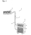
- FIG. 1 The exterior of an air conditioner in which a first embodiment of the present invention has been adapted is shown in Fig. 1.
- the air conditioner 1 is comprised of an indoor unit 2 that is installed on an indoor wall or the like, and an outdoor unit 3 that is disposed outdoors.
- the outdoor unit 3 is comprised of an outdoor air conditioner unit 5 that contains an outdoor heat exchanger, an outdoor fan, and the like, and a humidifying unit 4 that conveys humidified air to the indoor unit 2.
- the indoor unit 2 contains an indoor heat exchanger
- the outdoor unit 3 contains an outdoor heat exchanger
- each heat exchanger is connected to a refrigerant circuit by means of a refrigerant line 6.
- a humidified air line 7 that supplies humidified air from the humidifying unit 4 to the indoor unit 2 is provided between the humidifying unit 4 and the indoor unit 2.
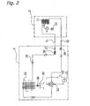
- FIG. 2 An example of the refrigerant circuit employed in the air conditioner 1 is shown in Fig. 2.
- the indoor heat exchanger 11 is provided in the indoor unit 2.
- the indoor heat exchanger 11 is comprised of a heat transfer line that has a plurality of curved portions on both ends thereof in the lengthwise direction, and a plurality of fins through which the heat transfer line passes, and exchanges heat with the air that comes in contact therewith.
- a cross flow fan 12 that takes in indoor air, and discharges this air indoors after heat exchange has taken place with the indoor heat exchanger 11, is provided in the indoor unit 2.
- the cross flow fan 12 is cylindrical in shape, is comprised of blades disposed around the circumferential surface of a rotary shaft, and generates air flow in a direction that is perpendicular to the rotary shaft.
- the cross flow fan 12 driven by means of a fan motor 13 that is provided inside the indoor unit 2.
- the decompressor 25 is connected to a local line 31 via a filter 26 and a liquid shut off valve 27, and is connected to one end of the indoor heat exchanger 11 via the local line 31.
- the four way directional control valve 22 is connected to a local line 32 via a gas shut off valve 28, and is connected to the other end of the indoor heat exchanger 11 via this local line 32.
- the local lines 31, 32 correspond to the refrigerant line 6 shown in Fig. 1.
- a propeller fan 29 that discharges air outside after heat exchange with the outdoor heat exchanger 24 is provided in the outdoor air conditioning unit 5.
- the propeller fan 29 is driven by a fan motor 30.
- the humidifying unit 4 is comprised of a humidifying unit casing 48 that is positioned on the upper portion of the outdoor unit 3.
- a humidifying rotor 58 is disposed inside the humidifying unit casing 48.
- the humidifying rotor 58 adsorbs moisture from the air that it comes in contact with, and is composed of a porous, disk shaped zeolite that has the ability to desorb the adsorbed moisture by heating.
- the humidifying rotor 58 is rotatably supported on a support shaft 59 provided on the humidifying unit casing 48 via a rotor guide 60.
- Gear teeth are formed on the circumferential surface of the humidifying rotor 58, which engage with a rotor drive gear 62 that is installed on a drive shaft on a rotor drive motor 61.
- a heater assembly 64 is disposed on the upper surface of the humidifying rotor 58 such that it covers approximately half thereof.
- the heater assembly 64 is composed of a heating element 66, an upper cover 65 that covers the heating element 66, and a lower cover 69 that includes an intake port 67 for air intake and a discharge port 68 that discharges air that has been heated by the heating element 66.
- the heater assembly 64 is installed above the humidifying rotor 58 via a heater connection plate 63.
- a humidifying fan 70 is disposed below the humidifying rotor 58 in a position facing the heating assembly 64.
- the humidifying fan 70 is a centrifugal fan that is disposed inside the casing and connected to a humidifying side connection duct 72, and is integral with a humidifying fan inlet 71 that is installed below the humidifying rotor 58.
- the humidifying fan 70 discharges air that has flowed through the humidifying rotor 58 into the connection duct 72, and sends humidified air to the indoor unit 2 via a humidifying hose 73 and the humidified air line 7.
- An adsorption side connection duct 74 is provided on the upper surface of the humidifying rotor 58 such that it covers the portion thereof not covered by the heater assembly 64.
- the adsorption side connection duct 74 forms an air flow route that runs from below the humidifying rotor 58, through the humidifying rotor 58, and ends in a adsorption fan container 75 that is adjacent to the container for the humidifying rotor 58.
- a bell mouth 84 that includes a port 85 that connects to the air flow route formed by the adsorption duct 74 is provided above the adsorption fan container 75.
- An adsorption fan 81 is contained in the adsorption fan container 75 and is freely rotatable therein.
- the adsorption fan 81 is a centrifugal fan that is structured so as to take in air from the adsorption side of the bell mouth 84, and discharge this air toward the rear of the adsorption fan container 75.
- the adsorption fan 81 is driven by an adsorption fan motor 83.
- the adsorption fan motor 83 is fixed inside the humidifying unit casing 48 by means of a motor mount 82.
- an air flow is generated by driving the adsorption fan 81, in which air is taken in from the outside, passes through a portion of the humidifying rotor 58, and is discharged to the rear via the adsorption connecting duct and the adsorption fan 81.
- the humidifying rotor 58 adsorbs moisture contained therein.
- an air flow is generated by driving the humidifying fan 70, in which air is taken in from the outside, passes through the humidifying rotor 58 from the lower part to the upper part thereof, is introduced into the upper cover 65 from the lower cover 69 of the intake port 67, is discharged from the discharge port 68 and passed through the humidifying rotor 58 a second time from the upper part to the lower part thereof, and is discharged to the humidifying side connecting duct 72.
- the air flow introduced from the outside comes into contact with the heating element 66 disposed inside the upper cover 65 of the heater assembly 64 and is heated.
- moisture adsorbed in the humidifying rotor 58 can be desorbed and supplied to the indoor unit 2 as humidified air by means of the air flow generated by the humidifying fan 70.
- FIG. 4 An exploded, perspective view of the indoor unit 2 is shown in Fig. 4.
- the indoor unit 2 includes a front grill assembly 101, and a front panel 102 that is mounted on the front of the front grill assembly 101.
- the front grill assembly 101 is comprised of an upper intake port 103 that is formed from a number of slit-shaped openings on the upper surface thereof.
- the front panel 102 is formed from a front intake port 104 that is open on the upper portion and side portions thereof.
- Air filters 105 are interposed between the upper intake port 103 of the front grill assembly 101 and the front intake port 104 of the front panel 102, and serve to clean the air.
- the front grill assembly 101 is installed on a base frame assembly 106 that is positioned on the rear thereof, and is configured to be a casing that contains the internal parts of the indoor unit 2.
- the casing composed of the front grill assembly 102 and the base frame assembly 106 is latched onto an installation plate 107 that is fixed onto an indoor wall, and thereby installed indoors.
- a fan container 109 that stores the cross flow fan 12 is provided in the base frame assembly 106.
- the cross flow fan 12 is installed such that it is freely rotatable via a bearing member 110, and the indoor fan motor 13 is provided on the side of the cross flow fan 12 opposite the bearing member 110.
- a side plate 111 is installed on the outer side of the indoor fan motor 13.
- the indoor heat exchanger 11 is installed such that it surrounds the cross flow fan 12 on the front, top and upper rear portion thereof.
- the indoor heat exchanger 11 includes a large number of cooling fins installed on a heat transfer line that has a plurality of curved portions on both ends thereof in the lengthwise direction. Air that has been taken in from the upper intake port 103 and the front intake port 104 by operation of the cross flow fan 12 passes through the cross flow fan 12 and exchanges heat with the refrigerant that flows inside the heat transfer line.
- the indoor heat exchanger 11 is connected to the refrigerant line from the outdoor unit 3 via a refrigerant line 108 that extends from the indoor heat exchanger 11.
- a drain pan 112 for receiving condensed water produced during heat exchange is provided on the lower part of the indoor heat exchanger 11.
- a drain hose 113 for discharging condensed water to the outside is installed on the drain pan 112.
- the drain pan 112 is constructed to receive the condensed water produced thereby, and drain it off via the drain hose 113.
- An electrical equipment box 114 that contains a printed circuit board that includes a control circuit and the like thereon, and an electrical equipment cover 115 that covers the front of the electrical equipment box 114, are provided on the lower front portion of the front grill assembly 101.
- a discharge port for the air flow that is generated by the cross flow fan 12 is provided on the lower portion of the electrical equipment box 114.
- Horizontal blades 116, 116, and a plurality of vertical blades 117, 117 that are connected to vertical blade connecting rods 118, are pivotably disposed on the discharge port.
- the horizontal blades 116, 116 are constructed such that they can be pivoted up and down by a horizontal blade operation motor 119, and the vertical blades 117, 117 are constructed such that they can be pivoted from left to right by a vertical blade operation motor 120.
- a duct assembly 171 is installed on one side of the base frame assembly 106.
- the duct assembly 171 is comprised of a humidifying hose connector 172 positioned on the bottom thereof, a duct formation 173 positioned in the middle thereof, and a humidified air discharge port 174 that is positioned on the upper portion thereof.
- the humidified air line 7 (shown in Fig. 1) is connected to the humidifying hose connector 172 of the duct assembly 171, and introduces humidified air supplied from the humidifying unit 4.
- the duct formation 173 positioned in the middle of the duct assembly 171 forms a space in which humidified air passes therethrough. Humidified air introduced from the humidifying hose connector 172 is conveyed to the end of the duct assembly 171, and is discharged into the air flow generated by the cross flow fan 12 from the humidified air discharge port 174.
- the humidified air discharge port 174 of the duct assembly 171 is disposed such that the humidified air is discharged parallel with respect to the cooling fins provided on the indoor heat exchanger 11, and generates a humidified air flow that is parallel to the air flow generated by the cross flow fan 12.
- the humidified air discharged from the humidified air discharge port 174 can be prevented from generating noise cause by the air flowing across the cooling fins of the indoor heat exchanger 11, thereby allowing a quite indoor unit 2 to be devised.
- the humidified air discharge port is disposed such that the humidified air supplied from the humidifying unit is discharged in a direction that is parallel with respect to the cooling fins of the indoor heat exchanger, the generation of operational noise due to the humidified air blowing across the cooling fins can be suppressed, and a quite indoor unit can be devised.
Landscapes
- Engineering & Computer Science (AREA)
- Chemical & Material Sciences (AREA)
- Combustion & Propulsion (AREA)
- Mechanical Engineering (AREA)
- General Engineering & Computer Science (AREA)
- Physics & Mathematics (AREA)
- Thermal Sciences (AREA)
- Air Humidification (AREA)
- Central Air Conditioning (AREA)
- Air Filters, Heat-Exchange Apparatuses, And Housings Of Air-Conditioning Units (AREA)
- Devices For Blowing Cold Air, Devices For Blowing Warm Air, And Means For Preventing Water Condensation In Air Conditioning Units (AREA)
Abstract
Description
Claims (3)
- An air conditioner (1), comprising:wherein a humidified air discharge port (174) is disposed such that a direction that said humidified air supplied from said humidifying unit (4) is discharged is parallel with respect to said cooling fins (177) of said indoor heat exchanger (11).an outdoor air conditioning unit having an outdoor refrigerant circuit (5);an indoor air conditioning unit (2) having an indoor heat exchanger (11) connected to said outdoor refrigerant circuit and in which a plurality of planar cooling fins (177) are installed in parallel on a heat transfer line that is curved from left to right on both ends thereof, and an indoor fan (12) that generates an air flow that passes through said cooling fins (177) on said indoor heat exchanger (11); anda humidifying unit (4) that removes moisture from outside air and generates humidified air, and supplies said humidified air to said indoor air conditioner (2);
- The air conditioner set forth in claim 1, wherein said indoor air conditioner (2) comprises an air filter (195) disposed between air introduction ports (103, 104) for introducing outside air and said indoor heat exchanger (11), and said humidified air discharge port (174) is disposed between said indoor heat exchanger (11) and said air filter (105).
- The air conditioner set forth in claim 1, wherein said indoor air conditioner (2) comprises an air filter (105) disposed between air introduction ports (103, 104) for introducing outside air and said indoor heat exchanger (11), and said humidified air discharge port (174) is disposed between said air introduction ports (103, 104) and said air filter (105).
Applications Claiming Priority (3)
| Application Number | Priority Date | Filing Date | Title |
|---|---|---|---|
| JP2000276293A JP2002089897A (en) | 2000-09-12 | 2000-09-12 | Air conditioner |
| JP2000276293 | 2000-09-12 | ||
| PCT/JP2001/007338 WO2002023096A1 (en) | 2000-09-12 | 2001-08-27 | Air conditioner |
Publications (3)
| Publication Number | Publication Date |
|---|---|
| EP1318356A1 true EP1318356A1 (en) | 2003-06-11 |
| EP1318356A4 EP1318356A4 (en) | 2005-11-16 |
| EP1318356B1 EP1318356B1 (en) | 2010-12-01 |
Family
ID=18761788
Family Applications (1)
| Application Number | Title | Priority Date | Filing Date |
|---|---|---|---|
| EP01958535A Expired - Lifetime EP1318356B1 (en) | 2000-09-12 | 2001-08-27 | Air conditioner |
Country Status (8)
| Country | Link |
|---|---|
| EP (1) | EP1318356B1 (en) |
| JP (1) | JP2002089897A (en) |
| KR (1) | KR20020061594A (en) |
| CN (1) | CN1162658C (en) |
| AT (1) | ATE490441T1 (en) |
| DE (1) | DE60143582D1 (en) |
| ES (1) | ES2356428T3 (en) |
| WO (1) | WO2002023096A1 (en) |
Cited By (2)
| Publication number | Priority date | Publication date | Assignee | Title |
|---|---|---|---|---|
| EP3073202A4 (en) * | 2013-11-20 | 2016-12-28 | Daikin Ind Ltd | OUTDOOR UNIT OF AIR CONDITIONER |
| CN112833468A (en) * | 2019-11-22 | 2021-05-25 | 三星电子株式会社 | air conditioner |
Families Citing this family (9)
| Publication number | Priority date | Publication date | Assignee | Title |
|---|---|---|---|---|
| CN104566626B (en) * | 2013-10-12 | 2018-05-15 | 珠海格力电器股份有限公司 | Air duct machine |
| JP6217522B2 (en) * | 2014-05-21 | 2017-10-25 | 株式会社デンソー | Humidifier |
| JP2023023960A (en) * | 2021-08-06 | 2023-02-16 | ダイキン工業株式会社 | Air-conditioning indoor unit |
| JP7181488B1 (en) * | 2021-08-06 | 2022-12-01 | ダイキン工業株式会社 | Air conditioner indoor unit and air conditioner |
| JP2023023959A (en) * | 2021-08-06 | 2023-02-16 | ダイキン工業株式会社 | Air-conditioning indoor unit |
| JP7141003B1 (en) * | 2021-08-06 | 2022-09-22 | ダイキン工業株式会社 | air conditioning indoor unit |
| JP7397027B2 (en) * | 2021-08-06 | 2023-12-12 | ダイキン工業株式会社 | air conditioning indoor unit |
| JP7168891B1 (en) * | 2021-08-06 | 2022-11-10 | ダイキン工業株式会社 | air conditioning indoor unit |
| JP7792560B2 (en) * | 2021-09-17 | 2025-12-26 | パナソニックIpマネジメント株式会社 | air conditioner |
Family Cites Families (6)
| Publication number | Priority date | Publication date | Assignee | Title |
|---|---|---|---|---|
| JPS62160230U (en) * | 1986-03-31 | 1987-10-12 | ||
| JPH0674502A (en) * | 1992-08-28 | 1994-03-15 | Mitsubishi Heavy Ind Ltd | Air conditioner |
| JP3157994B2 (en) * | 1994-10-28 | 2001-04-23 | シャープ株式会社 | Air conditioner with humidification function |
| JP2989513B2 (en) * | 1995-04-03 | 1999-12-13 | シャープ株式会社 | Air conditioner with dehumidification function |
| JP3120025B2 (en) * | 1995-08-24 | 2000-12-25 | シャープ株式会社 | Air conditioner |
| JP3430983B2 (en) * | 1999-07-28 | 2003-07-28 | ダイキン工業株式会社 | Air conditioner with humidification function |
-
2000
- 2000-09-12 JP JP2000276293A patent/JP2002089897A/en active Pending
-
2001
- 2001-08-27 KR KR1020027003043A patent/KR20020061594A/en not_active Ceased
- 2001-08-27 EP EP01958535A patent/EP1318356B1/en not_active Expired - Lifetime
- 2001-08-27 CN CNB01802615XA patent/CN1162658C/en not_active Expired - Fee Related
- 2001-08-27 WO PCT/JP2001/007338 patent/WO2002023096A1/en not_active Ceased
- 2001-08-27 ES ES01958535T patent/ES2356428T3/en not_active Expired - Lifetime
- 2001-08-27 DE DE60143582T patent/DE60143582D1/en not_active Expired - Lifetime
- 2001-08-27 AT AT01958535T patent/ATE490441T1/en not_active IP Right Cessation
Cited By (5)
| Publication number | Priority date | Publication date | Assignee | Title |
|---|---|---|---|---|
| EP3073202A4 (en) * | 2013-11-20 | 2016-12-28 | Daikin Ind Ltd | OUTDOOR UNIT OF AIR CONDITIONER |
| CN112833468A (en) * | 2019-11-22 | 2021-05-25 | 三星电子株式会社 | air conditioner |
| EP3825615A1 (en) * | 2019-11-22 | 2021-05-26 | Samsung Electronics Co., Ltd. | Air conditioner |
| US11578877B2 (en) | 2019-11-22 | 2023-02-14 | Samsung Electronics Co., Ltd. | Air conditioner having fan module with installation space and stabilizer modifier spaced apart from the fan module |
| CN112833468B (en) * | 2019-11-22 | 2024-03-29 | 三星电子株式会社 | Air conditioner |
Also Published As
| Publication number | Publication date |
|---|---|
| WO2002023096A1 (en) | 2002-03-21 |
| KR20020061594A (en) | 2002-07-24 |
| CN1388884A (en) | 2003-01-01 |
| EP1318356A4 (en) | 2005-11-16 |
| DE60143582D1 (en) | 2011-01-13 |
| EP1318356B1 (en) | 2010-12-01 |
| JP2002089897A (en) | 2002-03-27 |
| ATE490441T1 (en) | 2010-12-15 |
| ES2356428T3 (en) | 2011-04-08 |
| CN1162658C (en) | 2004-08-18 |
Similar Documents
| Publication | Publication Date | Title |
|---|---|---|
| JP3786090B2 (en) | Air conditioner and control method of air conditioner | |
| EP1318356B1 (en) | Air conditioner | |
| CN100425920C (en) | Ventilator and air conditioner | |
| EP2016341B1 (en) | Dehumidifier | |
| JP3719118B2 (en) | Air conditioner | |
| JP4677658B2 (en) | Air conditioner | |
| JP2008145090A (en) | Air conditioner indoor unit | |
| EP1318355B1 (en) | Air conditioner | |
| JP2004069173A (en) | Air conditioner | |
| JP3564525B2 (en) | Air conditioner | |
| CN100472140C (en) | Air conditioner | |
| JP3023361B1 (en) | Heat exchange type ventilation system | |
| JP2004053198A (en) | Air conditioner outdoor unit and air conditioner | |
| JP3900004B2 (en) | Air conditioner | |
| JP3564526B2 (en) | Air conditioner | |
| CN214664850U (en) | Air conditioning apparatus | |
| CN102478299A (en) | Motor fan assembly of indoor unit of split wall-mounted air conditioner | |
| JP3731570B2 (en) | Humidification unit for air conditioner and air conditioner | |
| JP2002089893A (en) | Air conditioner | |
| JP2002089903A (en) | Air conditioner | |
| JP2024039536A (en) | air conditioner | |
| JP3858914B2 (en) | Ventilator and air conditioner | |
| WO2001007839A1 (en) | Air conditioner with humidifying function | |
| JP2008281238A (en) | Air supply / exhaust system |
Legal Events
| Date | Code | Title | Description |
|---|---|---|---|
| PUAI | Public reference made under article 153(3) epc to a published international application that has entered the european phase |
Free format text: ORIGINAL CODE: 0009012 |
|
| 17P | Request for examination filed |
Effective date: 20020603 |
|
| AK | Designated contracting states |
Designated state(s): AT BE CH CY DE DK ES FI FR GB GR IE IT LI LU MC NL PT SE |
|
| A4 | Supplementary search report drawn up and despatched |
Effective date: 20050929 |
|
| RIC1 | Information provided on ipc code assigned before grant |
Ipc: 7F 24F 6/00 A Ipc: 7F 24F 6/06 B Ipc: 7F 24F 13/24 B Ipc: 7F 24F 3/14 B Ipc: 7F 24F 1/00 B |
|
| 17Q | First examination report despatched |
Effective date: 20061211 |
|
| GRAP | Despatch of communication of intention to grant a patent |
Free format text: ORIGINAL CODE: EPIDOSNIGR1 |
|
| RBV | Designated contracting states (corrected) |
Designated state(s): AT BE CH CY DE DK ES FI FR GB GR IE IT LI LU MC NL PT SE TR |
|
| GRAS | Grant fee paid |
Free format text: ORIGINAL CODE: EPIDOSNIGR3 |
|
| GRAA | (expected) grant |
Free format text: ORIGINAL CODE: 0009210 |
|
| AK | Designated contracting states |
Kind code of ref document: B1 Designated state(s): AT BE CH CY DE DK ES FI FR GB GR IE IT LI LU MC NL PT SE TR |
|
| REG | Reference to a national code |
Ref country code: GB Ref legal event code: FG4D |
|
| REG | Reference to a national code |
Ref country code: CH Ref legal event code: EP |
|
| REG | Reference to a national code |
Ref country code: IE Ref legal event code: FG4D |
|
| REF | Corresponds to: |
Ref document number: 60143582 Country of ref document: DE Date of ref document: 20110113 Kind code of ref document: P |
|
| REG | Reference to a national code |
Ref country code: NL Ref legal event code: VDEP Effective date: 20101201 |
|
| REG | Reference to a national code |
Ref country code: ES Ref legal event code: FG2A Ref document number: 2356428 Country of ref document: ES Kind code of ref document: T3 Effective date: 20110408 |
|
| PG25 | Lapsed in a contracting state [announced via postgrant information from national office to epo] |
Ref country code: SE Free format text: LAPSE BECAUSE OF FAILURE TO SUBMIT A TRANSLATION OF THE DESCRIPTION OR TO PAY THE FEE WITHIN THE PRESCRIBED TIME-LIMIT Effective date: 20101201 Ref country code: AT Free format text: LAPSE BECAUSE OF FAILURE TO SUBMIT A TRANSLATION OF THE DESCRIPTION OR TO PAY THE FEE WITHIN THE PRESCRIBED TIME-LIMIT Effective date: 20101201 Ref country code: FI Free format text: LAPSE BECAUSE OF FAILURE TO SUBMIT A TRANSLATION OF THE DESCRIPTION OR TO PAY THE FEE WITHIN THE PRESCRIBED TIME-LIMIT Effective date: 20101201 Ref country code: CY Free format text: LAPSE BECAUSE OF FAILURE TO SUBMIT A TRANSLATION OF THE DESCRIPTION OR TO PAY THE FEE WITHIN THE PRESCRIBED TIME-LIMIT Effective date: 20101201 Ref country code: NL Free format text: LAPSE BECAUSE OF FAILURE TO SUBMIT A TRANSLATION OF THE DESCRIPTION OR TO PAY THE FEE WITHIN THE PRESCRIBED TIME-LIMIT Effective date: 20101201 |
|
| PG25 | Lapsed in a contracting state [announced via postgrant information from national office to epo] |
Ref country code: GR Free format text: LAPSE BECAUSE OF FAILURE TO SUBMIT A TRANSLATION OF THE DESCRIPTION OR TO PAY THE FEE WITHIN THE PRESCRIBED TIME-LIMIT Effective date: 20110302 |
|
| PG25 | Lapsed in a contracting state [announced via postgrant information from national office to epo] |
Ref country code: BE Free format text: LAPSE BECAUSE OF FAILURE TO SUBMIT A TRANSLATION OF THE DESCRIPTION OR TO PAY THE FEE WITHIN THE PRESCRIBED TIME-LIMIT Effective date: 20101201 Ref country code: PT Free format text: LAPSE BECAUSE OF FAILURE TO SUBMIT A TRANSLATION OF THE DESCRIPTION OR TO PAY THE FEE WITHIN THE PRESCRIBED TIME-LIMIT Effective date: 20110401 |
|
| PLBE | No opposition filed within time limit |
Free format text: ORIGINAL CODE: 0009261 |
|
| STAA | Information on the status of an ep patent application or granted ep patent |
Free format text: STATUS: NO OPPOSITION FILED WITHIN TIME LIMIT |
|
| PG25 | Lapsed in a contracting state [announced via postgrant information from national office to epo] |
Ref country code: DK Free format text: LAPSE BECAUSE OF FAILURE TO SUBMIT A TRANSLATION OF THE DESCRIPTION OR TO PAY THE FEE WITHIN THE PRESCRIBED TIME-LIMIT Effective date: 20101201 |
|
| 26N | No opposition filed |
Effective date: 20110902 |
|
| REG | Reference to a national code |
Ref country code: DE Ref legal event code: R097 Ref document number: 60143582 Country of ref document: DE Effective date: 20110902 |
|
| REG | Reference to a national code |
Ref country code: DE Ref legal event code: R097 Ref document number: 60143582 Country of ref document: DE Effective date: 20110902 |
|
| PG25 | Lapsed in a contracting state [announced via postgrant information from national office to epo] |
Ref country code: MC Free format text: LAPSE BECAUSE OF NON-PAYMENT OF DUE FEES Effective date: 20110831 |
|
| REG | Reference to a national code |
Ref country code: CH Ref legal event code: PL |
|
| GBPC | Gb: european patent ceased through non-payment of renewal fee |
Effective date: 20110827 |
|
| PG25 | Lapsed in a contracting state [announced via postgrant information from national office to epo] |
Ref country code: LI Free format text: LAPSE BECAUSE OF NON-PAYMENT OF DUE FEES Effective date: 20110831 Ref country code: CH Free format text: LAPSE BECAUSE OF NON-PAYMENT OF DUE FEES Effective date: 20110831 |
|
| REG | Reference to a national code |
Ref country code: IE Ref legal event code: MM4A |
|
| PG25 | Lapsed in a contracting state [announced via postgrant information from national office to epo] |
Ref country code: IE Free format text: LAPSE BECAUSE OF NON-PAYMENT OF DUE FEES Effective date: 20110827 |
|
| PG25 | Lapsed in a contracting state [announced via postgrant information from national office to epo] |
Ref country code: GB Free format text: LAPSE BECAUSE OF NON-PAYMENT OF DUE FEES Effective date: 20110827 |
|
| PG25 | Lapsed in a contracting state [announced via postgrant information from national office to epo] |
Ref country code: LU Free format text: LAPSE BECAUSE OF NON-PAYMENT OF DUE FEES Effective date: 20110827 |
|
| PG25 | Lapsed in a contracting state [announced via postgrant information from national office to epo] |
Ref country code: TR Free format text: LAPSE BECAUSE OF FAILURE TO SUBMIT A TRANSLATION OF THE DESCRIPTION OR TO PAY THE FEE WITHIN THE PRESCRIBED TIME-LIMIT Effective date: 20101201 |
|
| REG | Reference to a national code |
Ref country code: FR Ref legal event code: PLFP Year of fee payment: 16 |
|
| PGFP | Annual fee paid to national office [announced via postgrant information from national office to epo] |
Ref country code: IT Payment date: 20160822 Year of fee payment: 16 Ref country code: DE Payment date: 20160823 Year of fee payment: 16 |
|
| PGFP | Annual fee paid to national office [announced via postgrant information from national office to epo] |
Ref country code: FR Payment date: 20160712 Year of fee payment: 16 |
|
| PGFP | Annual fee paid to national office [announced via postgrant information from national office to epo] |
Ref country code: ES Payment date: 20160712 Year of fee payment: 16 |
|
| REG | Reference to a national code |
Ref country code: DE Ref legal event code: R119 Ref document number: 60143582 Country of ref document: DE |
|
| REG | Reference to a national code |
Ref country code: FR Ref legal event code: ST Effective date: 20180430 |
|
| PG25 | Lapsed in a contracting state [announced via postgrant information from national office to epo] |
Ref country code: DE Free format text: LAPSE BECAUSE OF NON-PAYMENT OF DUE FEES Effective date: 20180301 |
|
| PG25 | Lapsed in a contracting state [announced via postgrant information from national office to epo] |
Ref country code: IT Free format text: LAPSE BECAUSE OF NON-PAYMENT OF DUE FEES Effective date: 20170827 Ref country code: FR Free format text: LAPSE BECAUSE OF NON-PAYMENT OF DUE FEES Effective date: 20170831 |
|
| REG | Reference to a national code |
Ref country code: ES Ref legal event code: FD2A Effective date: 20181024 |
|
| PG25 | Lapsed in a contracting state [announced via postgrant information from national office to epo] |
Ref country code: ES Free format text: LAPSE BECAUSE OF NON-PAYMENT OF DUE FEES Effective date: 20170828 |