EP1318256B1 - Burglarproof retainer clip and method of manufacturing the retainer clip - Google Patents
Burglarproof retainer clip and method of manufacturing the retainer clip Download PDFInfo
- Publication number
- EP1318256B1 EP1318256B1 EP01963551A EP01963551A EP1318256B1 EP 1318256 B1 EP1318256 B1 EP 1318256B1 EP 01963551 A EP01963551 A EP 01963551A EP 01963551 A EP01963551 A EP 01963551A EP 1318256 B1 EP1318256 B1 EP 1318256B1
- Authority
- EP
- European Patent Office
- Prior art keywords
- parts
- retainer clip
- raised
- press
- contacting
- Prior art date
- Legal status (The legal status is an assumption and is not a legal conclusion. Google has not performed a legal analysis and makes no representation as to the accuracy of the status listed.)
- Expired - Lifetime
Links
- 238000004519 manufacturing process Methods 0.000 title description 4
- 230000003014 reinforcing effect Effects 0.000 claims description 27
- 230000002265 prevention Effects 0.000 description 7
- 230000004048 modification Effects 0.000 description 4
- 238000012986 modification Methods 0.000 description 4
- 238000000034 method Methods 0.000 description 3
- 101700004678 SLIT3 Proteins 0.000 description 1
- 102100027339 Slit homolog 3 protein Human genes 0.000 description 1
Images





Classifications
-
- E—FIXED CONSTRUCTIONS
- E05—LOCKS; KEYS; WINDOW OR DOOR FITTINGS; SAFES
- E05B—LOCKS; ACCESSORIES THEREFOR; HANDCUFFS
- E05B9/00—Lock casings or latch-mechanism casings ; Fastening locks or fasteners or parts thereof to the wing
- E05B9/08—Fastening locks or fasteners or parts thereof, e.g. the casings of latch-bolt locks or cylinder locks to the wing
- E05B9/084—Fastening of lock cylinders, plugs or cores
-
- F—MECHANICAL ENGINEERING; LIGHTING; HEATING; WEAPONS; BLASTING
- F16—ENGINEERING ELEMENTS AND UNITS; GENERAL MEASURES FOR PRODUCING AND MAINTAINING EFFECTIVE FUNCTIONING OF MACHINES OR INSTALLATIONS; THERMAL INSULATION IN GENERAL
- F16B—DEVICES FOR FASTENING OR SECURING CONSTRUCTIONAL ELEMENTS OR MACHINE PARTS TOGETHER, e.g. NAILS, BOLTS, CIRCLIPS, CLAMPS, CLIPS OR WEDGES; JOINTS OR JOINTING
- F16B2200/00—Constructional details of connections not covered for in other groups of this subclass
- F16B2200/20—Connections with hook-like parts gripping behind a blind side of an element to be connected
- F16B2200/205—Connections with hook-like parts gripping behind a blind side of an element to be connected the hook being a separate retainer
-
- Y—GENERAL TAGGING OF NEW TECHNOLOGICAL DEVELOPMENTS; GENERAL TAGGING OF CROSS-SECTIONAL TECHNOLOGIES SPANNING OVER SEVERAL SECTIONS OF THE IPC; TECHNICAL SUBJECTS COVERED BY FORMER USPC CROSS-REFERENCE ART COLLECTIONS [XRACs] AND DIGESTS
- Y10—TECHNICAL SUBJECTS COVERED BY FORMER USPC
- Y10T—TECHNICAL SUBJECTS COVERED BY FORMER US CLASSIFICATION
- Y10T24/00—Buckles, buttons, clasps, etc.
- Y10T24/44—Clasp, clip, support-clamp, or required component thereof
- Y10T24/44034—Dissociable gripping members
-
- Y—GENERAL TAGGING OF NEW TECHNOLOGICAL DEVELOPMENTS; GENERAL TAGGING OF CROSS-SECTIONAL TECHNOLOGIES SPANNING OVER SEVERAL SECTIONS OF THE IPC; TECHNICAL SUBJECTS COVERED BY FORMER USPC CROSS-REFERENCE ART COLLECTIONS [XRACs] AND DIGESTS
- Y10—TECHNICAL SUBJECTS COVERED BY FORMER USPC
- Y10T—TECHNICAL SUBJECTS COVERED BY FORMER US CLASSIFICATION
- Y10T24/00—Buckles, buttons, clasps, etc.
- Y10T24/44—Clasp, clip, support-clamp, or required component thereof
- Y10T24/44641—Clasp, clip, support-clamp, or required component thereof having gripping member formed from, biased by, or mounted on resilient member
- Y10T24/44684—Clasp, clip, support-clamp, or required component thereof having gripping member formed from, biased by, or mounted on resilient member with operator for moving biased engaging face
- Y10T24/44692—Camming or wedging element
-
- Y—GENERAL TAGGING OF NEW TECHNOLOGICAL DEVELOPMENTS; GENERAL TAGGING OF CROSS-SECTIONAL TECHNOLOGIES SPANNING OVER SEVERAL SECTIONS OF THE IPC; TECHNICAL SUBJECTS COVERED BY FORMER USPC CROSS-REFERENCE ART COLLECTIONS [XRACs] AND DIGESTS
- Y10—TECHNICAL SUBJECTS COVERED BY FORMER USPC
- Y10T—TECHNICAL SUBJECTS COVERED BY FORMER US CLASSIFICATION
- Y10T24/00—Buckles, buttons, clasps, etc.
- Y10T24/44—Clasp, clip, support-clamp, or required component thereof
- Y10T24/44641—Clasp, clip, support-clamp, or required component thereof having gripping member formed from, biased by, or mounted on resilient member
- Y10T24/44932—Clasp, clip, support-clamp, or required component thereof having gripping member formed from, biased by, or mounted on resilient member having specific surface material or irregularity on or along engaging face
-
- Y—GENERAL TAGGING OF NEW TECHNOLOGICAL DEVELOPMENTS; GENERAL TAGGING OF CROSS-SECTIONAL TECHNOLOGIES SPANNING OVER SEVERAL SECTIONS OF THE IPC; TECHNICAL SUBJECTS COVERED BY FORMER USPC CROSS-REFERENCE ART COLLECTIONS [XRACs] AND DIGESTS
- Y10—TECHNICAL SUBJECTS COVERED BY FORMER USPC
- Y10T—TECHNICAL SUBJECTS COVERED BY FORMER US CLASSIFICATION
- Y10T24/00—Buckles, buttons, clasps, etc.
- Y10T24/44—Clasp, clip, support-clamp, or required component thereof
- Y10T24/44983—Clasp, clip, support-clamp, or required component thereof formed from single rigid piece of material
-
- Y—GENERAL TAGGING OF NEW TECHNOLOGICAL DEVELOPMENTS; GENERAL TAGGING OF CROSS-SECTIONAL TECHNOLOGIES SPANNING OVER SEVERAL SECTIONS OF THE IPC; TECHNICAL SUBJECTS COVERED BY FORMER USPC CROSS-REFERENCE ART COLLECTIONS [XRACs] AND DIGESTS
- Y10—TECHNICAL SUBJECTS COVERED BY FORMER USPC
- Y10T—TECHNICAL SUBJECTS COVERED BY FORMER US CLASSIFICATION
- Y10T24/00—Buckles, buttons, clasps, etc.
- Y10T24/44—Clasp, clip, support-clamp, or required component thereof
- Y10T24/44983—Clasp, clip, support-clamp, or required component thereof formed from single rigid piece of material
- Y10T24/44991—Clasp, clip, support-clamp, or required component thereof formed from single rigid piece of material having specific surface irregularity on or along engaging face
-
- Y—GENERAL TAGGING OF NEW TECHNOLOGICAL DEVELOPMENTS; GENERAL TAGGING OF CROSS-SECTIONAL TECHNOLOGIES SPANNING OVER SEVERAL SECTIONS OF THE IPC; TECHNICAL SUBJECTS COVERED BY FORMER USPC CROSS-REFERENCE ART COLLECTIONS [XRACs] AND DIGESTS
- Y10—TECHNICAL SUBJECTS COVERED BY FORMER USPC
- Y10T—TECHNICAL SUBJECTS COVERED BY FORMER US CLASSIFICATION
- Y10T70/00—Locks
- Y10T70/70—Operating mechanism
- Y10T70/7441—Key
- Y10T70/7486—Single key
- Y10T70/7508—Tumbler type
- Y10T70/7559—Cylinder type
- Y10T70/7655—Cylinder attaching or mounting means
Definitions
- This invention concerns an antitheft retainer clip.
- this invention concerns an antitheft retainer clip, which has a press-contacting part, a raised part, and an inclining part for preventing twisting and turning and thereby preventing automobile theft.
- a prior-art retainer clip shall now be described by way of Fig. 1, Fig. 2 , and Fig. 3 .
- Typical prior-art retainer clips of this kind are known from for example DE-A-2656011 or JP-A-9170360 .
- Fig. 1 is a perspective view, showing the condition of attachment of a prior-art retainer clip
- Fig. 2 is a perspective view, showing the prior-art retainer clip
- Fig. 3 is a perspective view, showing a prior-art key cylinder.
- Inserted parts 106 of a retainer clip 105 with a substantially C-like planar shape are inserted into cylinder slits 104 provided in large and small anti-rotation protrusions 103 that are respectively formed in pairs on side end parts of a flange part 102 of a key cylinder 101, and the key cylinder was attached to an automotive body panel by the press-contacting of raisedparts 107 formedon the inserted parts against cylinder slit upper parts 108.
- symbol 109 indicates a hook that is provided for preventing the falling-off of the attached retainer clip.
- This invention has been made in view of the above points, and an object thereof is to provide an antitheft retainer clip, which is high in theft preventing ability and with which, even when a deforming force is applied directly or indirectly to a key cylinder by a screwdriver or other illicit unlocking tool, the turning of inserted parts is prevented and the sliding of the inserted parts is prevented as well to thereby prevent the key cylinder from becoming removed from the automotive body panel, and a method of manufacture of such an antitheft retainer clip.
- this invention provides an antitheft retainer clip according to claim 1.
- each press-contacting part formed by the provision of a slit in the corresponding inserted part of the retainer clip, is put in pressed contact against the upper part of the cylinder slit, provided in the corresponding anti-rotation protrusion formed on a side end part of the flange part of the key cylinder, the turning of the press-contacting parts can be prevented and the theft preventing ability can thus be improved.
- reinforcing parts formed by the provision of slits in the inserted parts of the retainer clip, ensures rigidity after attachment of the retainer clip, the sliding of the press-contacting part in transverse directions can be prevented and the theft preventing ability can thus be improved.
- FIG. 4 is a perspective view for explaining an example of an antitheft retainer clip to which this invention is applied.
- a retainer clip 1, shown here, is a retainer clip with a substantially C-like planar shape that is equipped with a pair of inserted parts 2, and each inserted part is provided with a slit 3 that forms a press-contacting part 4 and an auxiliary part 5.
- each press-contacting part is formed to be substantially the same in width as an upper part of a cylinder slit 9, provided at each of a pair of anti-rotation protrusions 8 formed on side end parts of a flange part 7 of a key cylinder 6.
- each press-contacting part is formed a raised part 10, which is put in pressed contact against the upper part of the cylinder slit, an inclining part 11, which is continuous to the raised part and is inclined slantingly downwards, and a protruding part 12, which engages with a protrusion of the key cylinder.
- each raised part is formed a protrusion-like part 14 that protrudes towards an automotive body panel 13.
- each auxiliarypart is formed an auxiliary recessed part 15 that is recessed with respect to the automotive body panel.
- the press-contacting part and the auxiliary part are formed to be connected at a front end part and a base end part of the inserted part.
- each press-contacting part and auxiliary part be formed by the provision of a slit in each inserted part, and this slit therefore is not restricted to being formed as a cut but may instead be a punched shape, etc. of narrow width.
- the press-contacting of each press-contacting part against the upper part of the cylinder slit improves the theft preventing ability by preventing the turning of the press-contacting part and that the auxiliary parts improve the theft preventing ability by preventing the sliding of the press-contacting parts in transverse directions.
- the press-contacting parts and the auxiliary parts therefore do not necessarily have to be formed to be connected at the front end parts and base end parts of the inserted parts, it is preferable for thepress-contactingparts and the auxiliary parts to be formed to be connected at the front end parts and base end parts of the insertedparts so as to enable the auxiliary parts to prevent the sliding of the press-contacting parts in transverse directions more efficiently.
- the auxiliary recessed parts do not have to be formed necessarily as long as the sliding of the press-contacting parts in transverse directions can be prevented by the auxiliary parts
- the auxiliary recessed parts are preferably formed so as to be recessed with respect to the automotive body panel in order to enable the auxiliary parts to prevent the sliding of the press-contacting parts in transverse directions more efficiently.
- the auxiliary recessed parts may be recessed parts of fixed depth, in order to enable adequate prevention of the sliding of the press-contacting parts in transverse directions, even in a case where the press-contacting parts are changed in position by a spring action, the recessed parts are preferably formed so as not to be of fixed depth, that is for example, the recessed parts are preferably formed to be small in the proportion of their central parts, etc.
- protruding parts do hot have to be formed necessarily, protruding parts that engage with protrusions on the key cylinder are preferably formed on the press-contacting parts so that by the engagement of the protrusions of the key cylinder with the protruding parts, the falling-off of the retainer clip can be prevented more effectively and the theft preventing ability can be improved further.
- protrusion-like parts which protrude towards the automotive body panel, are preferably formed on the raised parts so as to enable gaps between the raised parts and the automotive body panel to be reduced thereby minimize movement of the retainer clip in the axial direction of the key cylinder in a case where a deforming force is applied directly or indirectly by an illicit unlocking tool.
- each press-contacting part is put in pressed contact against the upper part of the cylinder slit to enable turning of the corresponding inserted part to be prevented even when a deforming force is applied directly or indirectly to the key cylinder by a screwdriver or other illicit unlocking tool, and the sliding of the press-contacting parts in transverse directions is prevented by the auxiliary parts.
- Fig. 7 is a perspective view for explaining another example of an antitheft retainer clip to which this invention is applied.
- the retainer clip 1 shown here is formed, from the developed condition shown in Fig. 8 , by folding press-contacting parts in direction indicated by symbol E in Fig. 8 .
- Retainer clip 1 is a retainer clip with a substantially C-like planar shape having a pair of inserted parts 2, and on each inserted part is formed a press-contacting part 4, which is put in pressed contact against an upper part of a cylinder slit, provided in each of a pair of anti-rotation protrusions formed on side end parts of a flange part of a key cylinder.
- each press-contacting part is formed to be substantially the same in width as the upper part of the cylinder slit and has formed thereon a raised part 10, which is put in pressed contact against the upper part of the cylinder slit, an inclining part 11, which is continuous to the raised part and is inclined slantingly downwards, and a protruding part 12, which engages with a protrusion of the key cylinder.
- an auxiliary recessed part 15 is formed so as to be recessed with respect to the automotive body panel at the outer side of the corresponding press-contacting part formed on the retainer clip.
- each press-contacting part be formed to be substantially the same in width as the upper part of the cylinder slit, and obviously, the press-contacting parts do not have to be formed necessarily by folding the press-contacting parts in the direction indicated by symbol E in Fig. 8 .
- auxiliary recessed parts do not have to be formed necessarily as long as the sliding of the press-contacting parts in transverse directions can be prevented by the joining of the front end parts of the press-contacting parts with the inserted parts
- auxiliary recessed parts are preferably formed at the inserted parts of the retainer clip so as to be recessed with respect to the automotive body panel and at the outer sides of the press-contacting parts formed on the retainer clip in order to enable more efficient prevention of the sliding of the press-contactingparts in transverse directions.
- the auxiliary recessed parts may be recessed parts of fixed depth, in order to enable adequate prevention of the sliding of the press-contacting parts in transverse directions, even in a case where the press-contacting parts are changed in position by a spring action, the recessed parts are preferably formed so as not to be of fixed depth, that is, for example, the recessed parts are preferably made small in the proportions of their central parts, etc. as in the above-described example of an antitheft retainer clip to which this invention is applied.
- protruding parts that engage with protrusions on the key cylinder are preferably formed on the press-contacting parts so that by the engagement of the protrusions of the key cylinder with the protruding parts, the falling-off of the retainer clip can be prevented more effectively and the theft preventing ability can be improved further.
- each press-contacting part is put in pressed contact against the upper part of the cylinder slit to enable the turning of the inserted parts to be prevented even when a deforming force is applied directly or indirectly to the key cylinder by a screwdriver or other illicit unlocking tool, and the sliding of the press-contacting parts in transverse directions is prevented.
- Fig. 9 is a perspective view for explaining yet another example of an antitheft retainer clip to which this invention is applied.
- a reinforcing plate 16 is formed at the automotive body panel side of inserted parts of a retainer clip, has a substantially C-like planar shape similar to the retainer clip, and has engaging parts 17 formed at four locations on the sides.
- the reinforcing plate reduce gaps between the automotive body panel and the retainer clip, and the reinforcing plate therefore does not have to have a substantially C-like planar shape as shown in Fig. 11 but may have a shape such as shown in Fig. 12 instead.
- the retainer clip and reinforcing plate are engaged and made integral for convenience of handling, and these two components obviouslydo not have to bemade integral necessarily. That is, the reinforcing plate may be attached to the cylinder slits and then the retainer clip may be attached to the cylinder slits.
- the reinforcing plate is preferably formed as shown in Fig. 13 . That is, the reinforcing plate is preferably formed with engaging parts 19 so that the falling-off of the retainer clip can be prevented not only by the engagement of the protruding parts 12 of the retainer clip with the key cylinder but also by the engagement of the engaging parts 19 of the reinforcing plate as well.
- the reinforcing plate may also have the shape shown in Fig. 14 . That is, the reinforcing plate may be of a shape with which the retainer clip and the reinforcing plate clamp and become attached to a cylinder retainer from both sides. Hooks 20, which are formed on the reinforcing plate, fit into slits provided in the retainer clip and enable further prevention of the falling-off of the retainer clip.
- the theft preventing ability is furthermore improved by further prevention of the turning of the retainer clip by a screwdriver or other illicit unlocking tool by the forming of a reinforcing plate.
- Fig. 16 is a perspective view for explaining even yet another example of an antitheft retainer clip to which this invention is applied.
- the reinforcing plate shown here is formed integral to inserted parts of a retainer clip, and is formed, from the developed condition shown in Fig. 17 , by folding the reinforcing plate in the direction indicated by the symbol F in Fig. 17 .
- the retainer clip and the reinforcing plate can be formed integrally and the efficiency of production of the retainer clip can be improved.
Landscapes
- Engineering & Computer Science (AREA)
- Mechanical Engineering (AREA)
- Lock And Its Accessories (AREA)
- Connection Of Plates (AREA)
- Vehicle Interior And Exterior Ornaments, Soundproofing, And Insulation (AREA)
- Insertion Pins And Rivets (AREA)
- Springs (AREA)
- Motor Or Generator Frames (AREA)
- Snaps, Bayonet Connections, Set Pins, And Snap Rings (AREA)
Abstract
Description
- This invention concerns an antitheft retainer clip. To be more specific, this invention concerns an antitheft retainer clip, which has a press-contacting part, a raised part, and an inclining part for preventing twisting and turning and thereby preventing automobile theft.
- A prior-art retainer clip shall now be described by way of
Fig. 1, Fig. 2 , andFig. 3 . Typical prior-art retainer clips of this kind are known from for exampleDE-A-2656011 orJP-A-9170360 -
Fig. 1 is a perspective view, showing the condition of attachment of a prior-art retainer clip,Fig. 2 is a perspective view, showing the prior-art retainer clip, andFig. 3 is a perspective view, showing a prior-art key cylinder. - Inserted
parts 106 of aretainer clip 105 with a substantially C-like planar shape are inserted intocylinder slits 104 provided in large and smallanti-rotation protrusions 103 that are respectively formed in pairs on side end parts of aflange part 102 of akey cylinder 101, and the key cylinder was attached to an automotive body panel by the press-contacting ofraisedparts 107 formedon the inserted parts against cylinder slitupper parts 108. InFig. 2 ,symbol 109 indicates a hook that is provided for preventing the falling-off of the attached retainer clip. - However, with the prior-art retainer clip, there was a problem in that since the width (symbol B in
Fig. 3 ) of each of the anti-rotation protrusions formed on the side end parts of the flange part of the key cylinder is smaller than the width (symbol A inFig. 2 ) of each of the inserted parts and only a part of each inserted part is thus press-contacted against the corresponding anti-rotation protrusion, when a deforming force is applied directly or indirectly to the key cylinder by a screwdriver or other illicit unlocking tool, the inserted parts became turned in the directions of symbols C inFig. 2 , causing the press-contacting of the inserted parts and anti-rotation protrusions to become disengaged, the retainer clip to fall off, and the key cylinder to become removed from the automotive body panel. - Though a means, wherein the inserted parts are made small in width so that the entire inserted parts are put in pressed contact against the anti-rotation protrusions, may be considered in regard to the above problem, with such a means, though the turning of the inserted parts can be prevented, the inserted parts can slide in transverse directions (directions indicated by symbol D in
Fig. 2 ) to cause the retainer clip to fall off and the key cylinder to become removed from the automotive body panel. - Though a means, wherein the inserted parts are made thick in plate thickness, may be considered for the prevention of sliding, such a means is not necessarily feasible in consideration of the requirement that, in the process of attaching or removing a retainer clip, the work be done within a fixed range of force.
- This invention has been made in view of the above points, and an object thereof is to provide an antitheft retainer clip, which is high in theft preventing ability and with which, even when a deforming force is applied directly or indirectly to a key cylinder by a screwdriver or other illicit unlocking tool, the turning of inserted parts is prevented and the sliding of the inserted parts is prevented as well to thereby prevent the key cylinder from becoming removed from the automotive body panel, and a method of manufacture of such an antitheft retainer clip.
- In order to achieve the above object, this invention provides an antitheft retainer clip according to
claim 1. - Here, since the entirety of each press-contacting part, formed by the provision of a slit in the corresponding inserted part of the retainer clip, is put in pressed contact against the upper part of the cylinder slit, provided in the corresponding anti-rotation protrusion formed on a side end part of the flange part of the key cylinder, the turning of the press-contacting parts can be prevented and the theft preventing ability can thus be improved.
- Also, since reinforcing parts, formed by the provision of slits in the inserted parts of the retainer clip, ensures rigidity after attachment of the retainer clip, the sliding of the press-contacting part in transverse directions can be prevented and the theft preventing ability can thus be improved.
-
-
Fig. 1 is a perspective view, showing the condition of attachment of a prior-art retainer clip. -
Fig. 2 is a perspective view, showing the prior-art retainer clip. -
Fig. 3 is a perspective view, showing a prior-art key cylinder. -
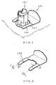
Fig. 4 is a perspective view for explaining an example of an antitheft retainer clip to which this invention is applied. -
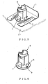
Fig. 5 is a perspective view, showing the condition of attachment of the antitheft retainer clip shown inFig. 4 . -
Fig. 6 is a perspective view, showing a key cylinder. -
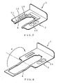
Fig. 7 is a perspective view for explaining another example of an antitheft retainer clip to which this invention is applied. -
Fig. 8 is a developed perspective view of the antitheft retainer clip shown inFig. 7 . -
Fig. 9 is a perspective view for explaining yet another example of an antitheft retainer clip to which this invention is applied. -
Fig. 10 is a perspective view, showing the main body of the retainer clip of the yet another example of an antitheft retainer clip to which this invention is applied. -
Fig. 11 is a perspective view, showing the reinforcing plate of the yet another example of an antitheft retainer clip to which this invention is applied. -
Fig. 12 is a perspective view, showing a modification example (1) of the reinforcing plate of the yet another example of an antitheft retainer clip to which this invention is applied. -
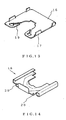
Fig. 13 is a perspective view, showing a modification example (2) of the reinforcing plate of the yet another example of an antitheft retainer clip towhich this invention is applied. -
Fig. 14 is a perspective view, showing a modification example (3) of the reinforcing plate of the yet another example of an antitheft retainer clip to which this invention is applied. -
Fig. 15 is a perspective view, showing the condition of attachment of the reinforcing plate modification example (3) shown inFig. 14 . -
Fig. 16 is a perspective view for explaining even yet another example of an antitheft retainer clip to which this invention is applied. -
Fig. 17 is a developed perspective view of the antitheft retainer clip shown inFig. 16 . - In order to further the understanding of this invention, embodiments of this invention shall now be described with reference to the drawings.
-
Fig. 4 is a perspective view for explaining an example of an antitheft retainer clip to which this invention is applied. Aretainer clip 1, shown here, is a retainer clip with a substantially C-like planar shape that is equipped with a pair of insertedparts 2, and each inserted part is provided with aslit 3 that forms a press-contactingpart 4 and anauxiliary part 5. - Here, each press-contacting part is formed to be substantially the same in width as an upper part of a cylinder slit 9, provided at each of a pair of
anti-rotation protrusions 8 formed on side end parts of aflange part 7 of akey cylinder 6. - Also, on each press-contacting part are formed a raised
part 10, which is put in pressed contact against the upper part of the cylinder slit, aninclining part 11, which is continuous to the raised part and is inclined slantingly downwards, and aprotruding part 12, which engages with a protrusion of the key cylinder. - Also on each raised part is formed a protrusion-
like part 14 that protrudes towards anautomotive body panel 13. - Also on each auxiliarypart is formed an auxiliary recessed
part 15 that is recessed with respect to the automotive body panel. - The press-contacting part and the auxiliary part are formed to be connected at a front end part and a base end part of the inserted part.
- Here, it is sufficient that each press-contacting part and auxiliary part be formed by the provision of a slit in each inserted part, and this slit therefore is not restricted to being formed as a cut but may instead be a punched shape, etc. of narrow width.
- Also, it is sufficient that the press-contacting of each press-contacting part against the upper part of the cylinder slit improves the theft preventing ability by preventing the turning of the press-contacting part and that the auxiliary parts improve the theft preventing ability by preventing the sliding of the press-contacting parts in transverse directions. Though the press-contacting parts and the auxiliary parts therefore do not necessarily have to be formed to be connected at the front end parts and base end parts of the inserted parts, it is preferable for thepress-contactingparts and the auxiliary parts to be formed to be connected at the front end parts and base end parts of the insertedparts so as to enable the auxiliary parts to prevent the sliding of the press-contacting parts in transverse directions more efficiently.
- Furthermore, though the auxiliary recessed parts do not have to be formed necessarily as long as the sliding of the press-contacting parts in transverse directions can be prevented by the auxiliary parts, the auxiliary recessed parts are preferably formed so as to be recessed with respect to the automotive body panel in order to enable the auxiliary parts to prevent the sliding of the press-contacting parts in transverse directions more efficiently.
- Also, though the auxiliary recessed parts may be recessed parts of fixed depth, in order to enable adequate prevention of the sliding of the press-contacting parts in transverse directions, even in a case where the press-contacting parts are changed in position by a spring action, the recessed parts are preferably formed so as not to be of fixed depth, that is for example, the recessed parts are preferably formed to be small in the proportion of their central parts, etc.
- Also, though the protruding parts do hot have to be formed necessarily, protruding parts that engage with protrusions on the key cylinder are preferably formed on the press-contacting parts so that by the engagement of the protrusions of the key cylinder with the protruding parts, the falling-off of the retainer clip can be prevented more effectively and the theft preventing ability can be improved further.
- Likewise, though the protrusion-like parts also do not have to be formed necessarily, protrusion-like parts, which protrude towards the automotive body panel, are preferably formed on the raised parts so as to enable gaps between the raised parts and the automotive body panel to be reduced thereby minimize movement of the retainer clip in the axial direction of the key cylinder in a case where a deforming force is applied directly or indirectly by an illicit unlocking tool.
- With the antitheft retainer clip to which this invention is applied, the entirety of each press-contacting part is put in pressed contact against the upper part of the cylinder slit to enable turning of the corresponding inserted part to be prevented even when a deforming force is applied directly or indirectly to the key cylinder by a screwdriver or other illicit unlocking tool, and the sliding of the press-contacting parts in transverse directions is prevented by the auxiliary parts.
-
Fig. 7 is a perspective view for explaining another example of an antitheft retainer clip to which this invention is applied. Theretainer clip 1 shown here is formed, from the developed condition shown inFig. 8 , by folding press-contacting parts in direction indicated by symbol E inFig. 8 . -
Retainer clip 1 is a retainer clip with a substantially C-like planar shape having a pair of insertedparts 2, and on each inserted part is formed a press-contactingpart 4, which is put in pressed contact against an upper part of a cylinder slit, provided in each of a pair of anti-rotation protrusions formed on side end parts of a flange part of a key cylinder. - Here, each press-contacting part is formed to be substantially the same in width as the upper part of the cylinder slit and has formed thereon a
raised part 10, which is put in pressed contact against the upper part of the cylinder slit, aninclining part 11, which is continuous to the raised part and is inclined slantingly downwards, and aprotruding part 12, which engages with a protrusion of the key cylinder. - Also, on each inserted part of the retainer clip, an auxiliary recessed
part 15 is formed so as to be recessed with respect to the automotive body panel at the outer side of the corresponding press-contacting part formed on the retainer clip. - Here, it is sufficient that each press-contacting part be formed to be substantially the same in width as the upper part of the cylinder slit, and obviously, the press-contacting parts do not have to be formed necessarily by folding the press-contacting parts in the direction indicated by symbol E in
Fig. 8 . - Also, though the auxiliary recessed parts do not have to be formed necessarily as long as the sliding of the press-contacting parts in transverse directions can be prevented by the joining of the front end parts of the press-contacting parts with the inserted parts, auxiliary recessed parts are preferably formed at the inserted parts of the retainer clip so as to be recessed with respect to the automotive body panel and at the outer sides of the press-contacting parts formed on the retainer clip in order to enable more efficient prevention of the sliding of the press-contactingparts in transverse directions. Also, though the auxiliary recessed parts may be recessed parts of fixed depth, in order to enable adequate prevention of the sliding of the press-contacting parts in transverse directions, even in a case where the press-contacting parts are changed in position by a spring action, the recessed parts are preferably formed so as not to be of fixed depth, that is, for example, the recessed parts are preferably made small in the proportions of their central parts, etc. as in the above-described example of an antitheft retainer clip to which this invention is applied.
- Furthermore as in the above-described example of an antitheft retainer clip to which this invention is applied, though the protruding parts do not have to be formed necessarily, protruding parts that engage with protrusions on the key cylinder are preferably formed on the press-contacting parts so that by the engagement of the protrusions of the key cylinder with the protruding parts, the falling-off of the retainer clip can be prevented more effectively and the theft preventing ability can be improved further.
- With the antitheft retainer clip to which this invention is applied, the entirety of each press-contacting part is put in pressed contact against the upper part of the cylinder slit to enable the turning of the inserted parts to be prevented even when a deforming force is applied directly or indirectly to the key cylinder by a screwdriver or other illicit unlocking tool, and the sliding of the press-contacting parts in transverse directions is prevented.
-
Fig. 9 is a perspective view for explaining yet another example of an antitheft retainer clip to which this invention is applied. Here, areinforcing plate 16 is formed at the automotive body panel side of inserted parts of a retainer clip, has a substantially C-like planar shape similar to the retainer clip, and has engagingparts 17 formed at four locations on the sides. - It is sufficient that the reinforcing plate reduce gaps between the automotive body panel and the retainer clip, and the reinforcing plate therefore does not have to have a substantially C-like planar shape as shown in
Fig. 11 but may have a shape such as shown inFig. 12 instead. - Here, the retainer clip and reinforcing plate are engaged and made integral for convenience of handling, and these two components obviouslydo not have to bemade integral necessarily. That is, the reinforcing plate may be attached to the cylinder slits and then the retainer clip may be attached to the cylinder slits.
- The reinforcing plate is preferably formed as shown in
Fig. 13 . That is, the reinforcing plate is preferably formed with engagingparts 19 so that the falling-off of the retainer clip can be prevented not only by the engagement of the protrudingparts 12 of the retainer clip with the key cylinder but also by the engagement of the engagingparts 19 of the reinforcing plate as well. - The reinforcing plate may also have the shape shown in
Fig. 14 . That is, the reinforcing plate may be of a shape with which the retainer clip and the reinforcing plate clamp and become attached to a cylinder retainer from both sides.Hooks 20, which are formed on the reinforcing plate, fit into slits provided in the retainer clip and enable further prevention of the falling-off of the retainer clip. - With an antitheft retainer clip to which this invention is applied, since inclining parts and raised parts are formed on press-contacting parts due to the disposing of a reinforcing plate between an automotive body panel and a retainer clip, and since auxiliary recessedparts are formed on auxiliaryparts, gaps between the automotive body panel and the retainer clip can be reduced and movement in the axial direction of the key cylinder in a case where a deforming force is applied directly or indirectly by an illicit unlocking tool can be minimized thereby realize further prevention of theft.
- The theft preventing ability is furthermore improved by further prevention of the turning of the retainer clip by a screwdriver or other illicit unlocking tool by the forming of a reinforcing plate.
-
Fig. 16 is a perspective view for explaining even yet another example of an antitheft retainer clip to which this invention is applied. The reinforcing plate shown here is formed integral to inserted parts of a retainer clip, and is formed, from the developed condition shown inFig. 17 , by folding the reinforcing plate in the direction indicated by the symbol F inFig. 17 . - With this antitheft retainer clip to which this invention is applied, the retainer clip and the reinforcing plate can be formed integrally and the efficiency of production of the retainer clip can be improved.
- As has been described above, with an antitheft retainer clip and a method of manufacture according to this invention, even when a deforming force is applied directly or indirectly to a key cylinder by a screwdriver or other illicit unlocking tool, the turning of inserted parts is prevented and the sliding of the inserted parts is prevented as well, thereby preventing the falling-off of the key cylinder or removal of the key cylinder from the automotive body panel and thus preventing the theft of an automobile.
Claims (8)
- An antitheft retainer clip, wherein a retainer clip (1) with a substantially C-like planar shape has a first part and a second part characterised in that each of the first part and the second part is provided with a slit (3) that forms a press-contacting part (4) and an auxiliary part (5), said antitheft retainer clip further comprising:- press-contacting parts (4) having a predetermined width;- raised parts (10), each formed on each of said press-contacting parts (4); and- inclining parts (11), each provided continuous to each of said raised parts.
- The antitheft retainer clip as set forth in Claim 1, wherein protrusion-like parts (14), which protrude in the opposite direction to the raised direction of said raised parts (10), are formed on said raised parts.
- The antitheft retainer clip as set forth in Claim 1, wherein auxiliary recessed parts (15), which are recessed in the same direction as the raised direction of said raised parts (10), are formed on said auxiliary parts (5).
- The antitheft retainer clip as set forth in Claim 1, wherein a reinforcing plate (16) is formed at the opposite side to a raised side of said first part and said second part, said raised side having the raised parts (10).
- The antitheft retainer clip as set forth in Claim 2, wherein auxiliary recessed parts (15), which are recessed in the same direction as the raised direction of said raised parts (10), are formed on said auxiliary parts (5).
- The antitheft retainer clip as set forth in Claim 2, wherein a reinforcing plate (16) is formed at the opposite side to a raised side of said first part and said second part, said raised side having the raised parts (10).
- The antitheft retainer clip as set forth in Claim 3, wherein a reinforcing plate (16) is formed at the opposite side to a raised side of said first part and said second part, said raised side having the raised parts (10).
- The antitheft retainer clip as set forth in Claim 5, wherein a reinforcing plate (16) is formed at opposite side to a raised side of said first part and said second part, said raised side having the raised parts (10).
Applications Claiming Priority (3)
| Application Number | Priority Date | Filing Date | Title |
|---|---|---|---|
| JP2000275787A JP3468363B2 (en) | 2000-09-12 | 2000-09-12 | Anti-theft retainer clip |
| JP2000275787 | 2000-09-12 | ||
| PCT/JP2001/007827 WO2002022997A1 (en) | 2000-09-12 | 2001-09-07 | Burglarproof retainer clip and method of manufacturing the retainer clip |
Publications (3)
| Publication Number | Publication Date |
|---|---|
| EP1318256A1 EP1318256A1 (en) | 2003-06-11 |
| EP1318256A4 EP1318256A4 (en) | 2008-03-12 |
| EP1318256B1 true EP1318256B1 (en) | 2011-04-20 |
Family
ID=18761350
Family Applications (1)
| Application Number | Title | Priority Date | Filing Date |
|---|---|---|---|
| EP01963551A Expired - Lifetime EP1318256B1 (en) | 2000-09-12 | 2001-09-07 | Burglarproof retainer clip and method of manufacturing the retainer clip |
Country Status (7)
| Country | Link |
|---|---|
| US (1) | US6901638B2 (en) |
| EP (1) | EP1318256B1 (en) |
| JP (1) | JP3468363B2 (en) |
| AT (1) | ATE506509T1 (en) |
| AU (1) | AU2001284500A1 (en) |
| DE (1) | DE60144481D1 (en) |
| WO (1) | WO2002022997A1 (en) |
Families Citing this family (22)
| Publication number | Priority date | Publication date | Assignee | Title |
|---|---|---|---|---|
| JP4106649B2 (en) * | 2002-11-29 | 2008-06-25 | スズキ株式会社 | Key cylinder mounting structure |
| US7412728B2 (en) * | 2004-08-27 | 2008-08-19 | 180S, Inc. | Garment with a venting structure and method of using the same |
| US8347676B2 (en) * | 2004-11-30 | 2013-01-08 | Valeo Sistemas Automotivos Ltda. | Constructive improvement to an anti-theft lock device applied to automobile trunks |
| DE102005014899B4 (en) * | 2005-04-01 | 2006-11-23 | Emka Beschlagteile Gmbh & Co. Kg | Cam lock with self-assembly |
| USD587100S1 (en) * | 2006-01-30 | 2009-02-24 | Louver-Lite Limited | Window blind frame clip |
| US7444845B2 (en) * | 2006-10-16 | 2008-11-04 | Chrysler Llc | Retainer for a door lock |
| CA2664496C (en) * | 2008-05-02 | 2017-05-09 | Magna International Inc. | Tolerance adjusting attachment |
| CA2667712C (en) * | 2009-06-01 | 2012-12-18 | Wesko Systems Limited | Lock core with releasable clasp for driver |
| DE102011000224A1 (en) * | 2010-10-18 | 2012-04-19 | Huf Hülsbeck & Fürst Gmbh & Co. Kg | Device for fastening an essential component |
| US8739584B2 (en) * | 2011-06-02 | 2014-06-03 | Chrysler Group Llc | Door lock retainer |
| CN202280317U (en) * | 2011-11-03 | 2012-06-20 | 纬创资通股份有限公司 | Easy-to-assemble latch mechanism and electronics |
| USD673843S1 (en) * | 2011-11-14 | 2013-01-08 | Koninklijke Philips Electronics N.V. | LED clamp |
| USD673845S1 (en) * | 2011-11-14 | 2013-01-08 | Koninklijke Philips Electronics N.V. | LED clamp |
| USD673844S1 (en) * | 2011-11-14 | 2013-01-08 | Koninklijke Philips Electronics N.V. | LED clamp |
| USD673842S1 (en) * | 2011-11-14 | 2013-01-08 | Koninklijke Philips Electronics N.V. | LED clamp |
| USD675511S1 (en) * | 2012-07-05 | 2013-02-05 | Commercial Christmas Clip Company, LLC | L-shaped clip |
| DE102012017088B4 (en) * | 2012-08-29 | 2015-07-09 | Audi Ag | Fastening element with several joining directions and corresponding fastening arrangement for the attachment of an attachment to a vehicle body |
| US9328535B2 (en) | 2014-01-17 | 2016-05-03 | Kwikset Corporation | Padlock cylinder retention |
| US10196842B2 (en) | 2014-06-20 | 2019-02-05 | Huf North America Automotive Parts Manufacturing Corp. | Retention mechanism for insertion member in vehicular door handle assembly |
| JP1517572S (en) * | 2014-07-24 | 2015-02-16 | ||
| US20190142085A1 (en) * | 2017-11-13 | 2019-05-16 | Honeywell International Inc. | Ergonomic sleeve harness and fasteners |
| CN112252842B (en) * | 2020-11-26 | 2025-06-20 | 江苏高雷德电力科技有限公司 | Passive smart lock |
Family Cites Families (19)
| Publication number | Priority date | Publication date | Assignee | Title |
|---|---|---|---|---|
| US2244427A (en) * | 1938-08-18 | 1941-06-03 | Flex O Tube Company | Method of making fastening devices |
| US2278708A (en) * | 1939-01-17 | 1942-04-07 | Flex O Tube Company | Method of making fastening devices |
| US2744185A (en) * | 1952-08-15 | 1956-05-01 | Cadre Ind Corp | Illuminated knob |
| US2950514A (en) * | 1958-03-12 | 1960-08-30 | Memphis Metal Mfg Co Inc | Carton lid holder |
| US3297916A (en) * | 1965-01-05 | 1967-01-10 | United Carr Inc | Fastener and heat conductor installation |
| US3683737A (en) * | 1969-10-30 | 1972-08-15 | Hans Oetiker | Detachable two-partite connecting arrangement |
| DE2656011C3 (en) * | 1976-12-10 | 1979-10-25 | Bayerische Motoren Werke Ag, 8000 Muenchen | External handle for motor vehicle doors |
| JPS5553640Y2 (en) * | 1977-06-09 | 1980-12-12 | ||
| JPS5410497A (en) | 1977-06-23 | 1979-01-26 | Mitsubishi Electric Corp | Method of laser working |
| FR2505814A1 (en) | 1981-05-13 | 1982-11-19 | Air Liquide | HIGH POROSITY SILICO-CALCAREOUS MASS AND PROCESS FOR PREPARING THE SAME |
| JPS6259777A (en) * | 1985-09-09 | 1987-03-16 | 株式会社 ユ−シン | Apparatus for mounting cylinder lock |
| JPH0349011A (en) | 1989-07-18 | 1991-03-01 | Hitachi Ltd | Thin-film magnetic head and production thereof |
| JPH0437773A (en) | 1990-06-01 | 1992-02-07 | Konica Corp | Color image forming device |
| US5636540A (en) * | 1993-12-20 | 1997-06-10 | Fort Lock Corporation | Lock clip |
| JP3376794B2 (en) | 1995-12-21 | 2003-02-10 | 日産自動車株式会社 | Key cylinder mounting structure for automobiles |
| JP3252348B2 (en) * | 1997-03-21 | 2002-02-04 | 株式会社パイオラックス | A fixing structure for fixing an attachment member having a metal clip and a through-hole and a shaft-shaped member via the metal clip |
| JP3253059B2 (en) | 1997-12-11 | 2002-02-04 | 株式会社ホンダロック | Mounting structure of cylinder lock |
| JP4064568B2 (en) * | 1999-04-21 | 2008-03-19 | 株式会社ユーシン | Cylinder lock mounting structure |
| JP2001336317A (en) * | 2000-05-31 | 2001-12-07 | Chuo Hatsujo Kogyo Kk | Anti-theft key cylinder retainer |
-
2000
- 2000-09-12 JP JP2000275787A patent/JP3468363B2/en not_active Expired - Fee Related
-
2001
- 2001-09-07 US US10/362,063 patent/US6901638B2/en not_active Expired - Fee Related
- 2001-09-07 AT AT01963551T patent/ATE506509T1/en not_active IP Right Cessation
- 2001-09-07 WO PCT/JP2001/007827 patent/WO2002022997A1/en not_active Ceased
- 2001-09-07 AU AU2001284500A patent/AU2001284500A1/en not_active Abandoned
- 2001-09-07 EP EP01963551A patent/EP1318256B1/en not_active Expired - Lifetime
- 2001-09-07 DE DE60144481T patent/DE60144481D1/en not_active Expired - Lifetime
Also Published As
| Publication number | Publication date |
|---|---|
| ATE506509T1 (en) | 2011-05-15 |
| DE60144481D1 (en) | 2011-06-01 |
| JP3468363B2 (en) | 2003-11-17 |
| WO2002022997A1 (en) | 2002-03-21 |
| EP1318256A1 (en) | 2003-06-11 |
| EP1318256A4 (en) | 2008-03-12 |
| US6901638B2 (en) | 2005-06-07 |
| AU2001284500A1 (en) | 2002-03-26 |
| JP2002089091A (en) | 2002-03-27 |
| US20030177618A1 (en) | 2003-09-25 |
Similar Documents
| Publication | Publication Date | Title |
|---|---|---|
| US6901638B2 (en) | Burglarproof retainer clip and method of manufacturing the retainer clip | |
| JP3346315B2 (en) | Wire harness fixing clip | |
| EP0627564A2 (en) | Panel locator and attachement apparatus | |
| EP1331141A2 (en) | Fixing method and structure of inflator, and airbag apparatus | |
| US5347691A (en) | Clip assembly | |
| US20010022336A1 (en) | Bracket for mounting an accessory on vehicle body | |
| JP6193204B2 (en) | Housing with automatic mounting structure | |
| JPH11230135A (en) | Article installation fixture | |
| JP4885638B2 (en) | Protector | |
| JP2007331744A (en) | Fog lamp mounting structure and mounting method thereof | |
| CN114435133A (en) | System and method for securing and positioning a component relative to another component | |
| WO2004074045A1 (en) | Load collapse prevention device | |
| JP2570768Y2 (en) | Lock device | |
| EP1817203B1 (en) | Auxiliary-handle fixing clip for modular headliner of automobile | |
| JP2011036030A (en) | Clip and wire harness with clip | |
| KR100408189B1 (en) | Clip | |
| GB2367536A (en) | Strap connection | |
| US5911468A (en) | Clamp and method for providing a clamp formed from a vehicle body or door panel | |
| JP2596574Y2 (en) | Automotive parts mounting equipment | |
| JP2001336317A (en) | Anti-theft key cylinder retainer | |
| JP2001065517A (en) | clip | |
| JPH0649928Y2 (en) | clip | |
| CN218992044U (en) | Clamp and system comprising same | |
| KR100204889B1 (en) | Jack handle fixing clip | |
| JP7662397B2 (en) | Fastener |
Legal Events
| Date | Code | Title | Description |
|---|---|---|---|
| PUAI | Public reference made under article 153(3) epc to a published international application that has entered the european phase |
Free format text: ORIGINAL CODE: 0009012 |
|
| 17P | Request for examination filed |
Effective date: 20030321 |
|
| AK | Designated contracting states |
Designated state(s): AT BE CH CY DE DK ES FI FR GB GR IE IT LI LU MC NL PT SE TR |
|
| A4 | Supplementary search report drawn up and despatched |
Effective date: 20080212 |
|
| 17Q | First examination report despatched |
Effective date: 20090202 |
|
| GRAP | Despatch of communication of intention to grant a patent |
Free format text: ORIGINAL CODE: EPIDOSNIGR1 |
|
| GRAS | Grant fee paid |
Free format text: ORIGINAL CODE: EPIDOSNIGR3 |
|
| GRAA | (expected) grant |
Free format text: ORIGINAL CODE: 0009210 |
|
| AK | Designated contracting states |
Kind code of ref document: B1 Designated state(s): AT BE CH CY DE DK ES FI FR GB GR IE IT LI LU MC NL PT SE TR |
|
| REG | Reference to a national code |
Ref country code: GB Ref legal event code: FG4D |
|
| REG | Reference to a national code |
Ref country code: CH Ref legal event code: EP |
|
| REG | Reference to a national code |
Ref country code: IE Ref legal event code: FG4D |
|
| REF | Corresponds to: |
Ref document number: 60144481 Country of ref document: DE Date of ref document: 20110601 Kind code of ref document: P |
|
| REG | Reference to a national code |
Ref country code: DE Ref legal event code: R096 Ref document number: 60144481 Country of ref document: DE Effective date: 20110601 |
|
| REG | Reference to a national code |
Ref country code: NL Ref legal event code: VDEP Effective date: 20110420 |
|
| PG25 | Lapsed in a contracting state [announced via postgrant information from national office to epo] |
Ref country code: PT Free format text: LAPSE BECAUSE OF FAILURE TO SUBMIT A TRANSLATION OF THE DESCRIPTION OR TO PAY THE FEE WITHIN THE PRESCRIBED TIME-LIMIT Effective date: 20110822 Ref country code: SE Free format text: LAPSE BECAUSE OF FAILURE TO SUBMIT A TRANSLATION OF THE DESCRIPTION OR TO PAY THE FEE WITHIN THE PRESCRIBED TIME-LIMIT Effective date: 20110420 |
|
| PG25 | Lapsed in a contracting state [announced via postgrant information from national office to epo] |
Ref country code: FI Free format text: LAPSE BECAUSE OF FAILURE TO SUBMIT A TRANSLATION OF THE DESCRIPTION OR TO PAY THE FEE WITHIN THE PRESCRIBED TIME-LIMIT Effective date: 20110420 Ref country code: ES Free format text: LAPSE BECAUSE OF FAILURE TO SUBMIT A TRANSLATION OF THE DESCRIPTION OR TO PAY THE FEE WITHIN THE PRESCRIBED TIME-LIMIT Effective date: 20110731 Ref country code: GR Free format text: LAPSE BECAUSE OF FAILURE TO SUBMIT A TRANSLATION OF THE DESCRIPTION OR TO PAY THE FEE WITHIN THE PRESCRIBED TIME-LIMIT Effective date: 20110721 Ref country code: CY Free format text: LAPSE BECAUSE OF FAILURE TO SUBMIT A TRANSLATION OF THE DESCRIPTION OR TO PAY THE FEE WITHIN THE PRESCRIBED TIME-LIMIT Effective date: 20110420 Ref country code: AT Free format text: LAPSE BECAUSE OF FAILURE TO SUBMIT A TRANSLATION OF THE DESCRIPTION OR TO PAY THE FEE WITHIN THE PRESCRIBED TIME-LIMIT Effective date: 20110420 Ref country code: BE Free format text: LAPSE BECAUSE OF FAILURE TO SUBMIT A TRANSLATION OF THE DESCRIPTION OR TO PAY THE FEE WITHIN THE PRESCRIBED TIME-LIMIT Effective date: 20110420 |
|
| PGFP | Annual fee paid to national office [announced via postgrant information from national office to epo] |
Ref country code: GB Payment date: 20110930 Year of fee payment: 11 |
|
| PG25 | Lapsed in a contracting state [announced via postgrant information from national office to epo] |
Ref country code: NL Free format text: LAPSE BECAUSE OF FAILURE TO SUBMIT A TRANSLATION OF THE DESCRIPTION OR TO PAY THE FEE WITHIN THE PRESCRIBED TIME-LIMIT Effective date: 20110420 |
|
| PGFP | Annual fee paid to national office [announced via postgrant information from national office to epo] |
Ref country code: FR Payment date: 20111013 Year of fee payment: 11 |
|
| PLBE | No opposition filed within time limit |
Free format text: ORIGINAL CODE: 0009261 |
|
| STAA | Information on the status of an ep patent application or granted ep patent |
Free format text: STATUS: NO OPPOSITION FILED WITHIN TIME LIMIT |
|
| PG25 | Lapsed in a contracting state [announced via postgrant information from national office to epo] |
Ref country code: DK Free format text: LAPSE BECAUSE OF FAILURE TO SUBMIT A TRANSLATION OF THE DESCRIPTION OR TO PAY THE FEE WITHIN THE PRESCRIBED TIME-LIMIT Effective date: 20110420 |
|
| 26N | No opposition filed |
Effective date: 20120123 |
|
| PG25 | Lapsed in a contracting state [announced via postgrant information from national office to epo] |
Ref country code: MC Free format text: LAPSE BECAUSE OF NON-PAYMENT OF DUE FEES Effective date: 20110930 |
|
| REG | Reference to a national code |
Ref country code: CH Ref legal event code: PL |
|
| REG | Reference to a national code |
Ref country code: DE Ref legal event code: R097 Ref document number: 60144481 Country of ref document: DE Effective date: 20120123 |
|
| PG25 | Lapsed in a contracting state [announced via postgrant information from national office to epo] |
Ref country code: IT Free format text: LAPSE BECAUSE OF FAILURE TO SUBMIT A TRANSLATION OF THE DESCRIPTION OR TO PAY THE FEE WITHIN THE PRESCRIBED TIME-LIMIT Effective date: 20110420 |
|
| REG | Reference to a national code |
Ref country code: IE Ref legal event code: MM4A |
|
| PG25 | Lapsed in a contracting state [announced via postgrant information from national office to epo] |
Ref country code: CH Free format text: LAPSE BECAUSE OF NON-PAYMENT OF DUE FEES Effective date: 20110930 Ref country code: IE Free format text: LAPSE BECAUSE OF NON-PAYMENT OF DUE FEES Effective date: 20110907 Ref country code: LI Free format text: LAPSE BECAUSE OF NON-PAYMENT OF DUE FEES Effective date: 20110930 |
|
| GBPC | Gb: european patent ceased through non-payment of renewal fee |
Effective date: 20120907 |
|
| PG25 | Lapsed in a contracting state [announced via postgrant information from national office to epo] |
Ref country code: LU Free format text: LAPSE BECAUSE OF NON-PAYMENT OF DUE FEES Effective date: 20110907 |
|
| REG | Reference to a national code |
Ref country code: FR Ref legal event code: ST Effective date: 20130531 |
|
| PG25 | Lapsed in a contracting state [announced via postgrant information from national office to epo] |
Ref country code: GB Free format text: LAPSE BECAUSE OF NON-PAYMENT OF DUE FEES Effective date: 20120907 Ref country code: DE Free format text: LAPSE BECAUSE OF NON-PAYMENT OF DUE FEES Effective date: 20130403 |
|
| PG25 | Lapsed in a contracting state [announced via postgrant information from national office to epo] |
Ref country code: FR Free format text: LAPSE BECAUSE OF NON-PAYMENT OF DUE FEES Effective date: 20121001 |
|
| REG | Reference to a national code |
Ref country code: DE Ref legal event code: R119 Ref document number: 60144481 Country of ref document: DE Effective date: 20130403 |
|
| PG25 | Lapsed in a contracting state [announced via postgrant information from national office to epo] |
Ref country code: TR Free format text: LAPSE BECAUSE OF FAILURE TO SUBMIT A TRANSLATION OF THE DESCRIPTION OR TO PAY THE FEE WITHIN THE PRESCRIBED TIME-LIMIT Effective date: 20110420 |