EP1318056A2 - Valve and method for a brake control actuator - Google Patents
Valve and method for a brake control actuator Download PDFInfo
- Publication number
- EP1318056A2 EP1318056A2 EP02078767A EP02078767A EP1318056A2 EP 1318056 A2 EP1318056 A2 EP 1318056A2 EP 02078767 A EP02078767 A EP 02078767A EP 02078767 A EP02078767 A EP 02078767A EP 1318056 A2 EP1318056 A2 EP 1318056A2
- Authority
- EP
- European Patent Office
- Prior art keywords
- ball
- valve
- mounting section
- rod
- section
- Prior art date
- Legal status (The legal status is an assumption and is not a legal conclusion. Google has not performed a legal analysis and makes no representation as to the accuracy of the status listed.)
- Withdrawn
Links
Images


Classifications
-
- F—MECHANICAL ENGINEERING; LIGHTING; HEATING; WEAPONS; BLASTING
- F16—ENGINEERING ELEMENTS AND UNITS; GENERAL MEASURES FOR PRODUCING AND MAINTAINING EFFECTIVE FUNCTIONING OF MACHINES OR INSTALLATIONS; THERMAL INSULATION IN GENERAL
- F16K—VALVES; TAPS; COCKS; ACTUATING-FLOATS; DEVICES FOR VENTING OR AERATING
- F16K31/00—Actuating devices; Operating means; Releasing devices
- F16K31/02—Actuating devices; Operating means; Releasing devices electric; magnetic
- F16K31/06—Actuating devices; Operating means; Releasing devices electric; magnetic using a magnet, e.g. diaphragm valves, cutting off by means of a liquid
- F16K31/0644—One-way valve
- F16K31/0655—Lift valves
-
- B—PERFORMING OPERATIONS; TRANSPORTING
- B60—VEHICLES IN GENERAL
- B60T—VEHICLE BRAKE CONTROL SYSTEMS OR PARTS THEREOF; BRAKE CONTROL SYSTEMS OR PARTS THEREOF, IN GENERAL; ARRANGEMENT OF BRAKING ELEMENTS ON VEHICLES IN GENERAL; PORTABLE DEVICES FOR PREVENTING UNWANTED MOVEMENT OF VEHICLES; VEHICLE MODIFICATIONS TO FACILITATE COOLING OF BRAKES
- B60T8/00—Arrangements for adjusting wheel-braking force to meet varying vehicular or ground-surface conditions, e.g. limiting or varying distribution of braking force
- B60T8/32—Arrangements for adjusting wheel-braking force to meet varying vehicular or ground-surface conditions, e.g. limiting or varying distribution of braking force responsive to a speed condition, e.g. acceleration or deceleration
- B60T8/34—Arrangements for adjusting wheel-braking force to meet varying vehicular or ground-surface conditions, e.g. limiting or varying distribution of braking force responsive to a speed condition, e.g. acceleration or deceleration having a fluid pressure regulator responsive to a speed condition
- B60T8/36—Arrangements for adjusting wheel-braking force to meet varying vehicular or ground-surface conditions, e.g. limiting or varying distribution of braking force responsive to a speed condition, e.g. acceleration or deceleration having a fluid pressure regulator responsive to a speed condition including a pilot valve responding to an electromagnetic force
- B60T8/3615—Electromagnetic valves specially adapted for anti-lock brake and traction control systems
- B60T8/363—Electromagnetic valves specially adapted for anti-lock brake and traction control systems in hydraulic systems
-
- F—MECHANICAL ENGINEERING; LIGHTING; HEATING; WEAPONS; BLASTING
- F16—ENGINEERING ELEMENTS AND UNITS; GENERAL MEASURES FOR PRODUCING AND MAINTAINING EFFECTIVE FUNCTIONING OF MACHINES OR INSTALLATIONS; THERMAL INSULATION IN GENERAL
- F16K—VALVES; TAPS; COCKS; ACTUATING-FLOATS; DEVICES FOR VENTING OR AERATING
- F16K31/00—Actuating devices; Operating means; Releasing devices
- F16K31/02—Actuating devices; Operating means; Releasing devices electric; magnetic
- F16K31/06—Actuating devices; Operating means; Releasing devices electric; magnetic using a magnet, e.g. diaphragm valves, cutting off by means of a liquid
- F16K31/0644—One-way valve
- F16K31/0655—Lift valves
- F16K31/0665—Lift valves with valve member being at least partially ball-shaped
Definitions
- the present invention is generally related to braking systems, and, more particularly, to a modified ball for a valve that controls passage of brake fluid in an actuator for controlled braking systems for vehicular applications.
- ABSs On controlled anti-lock braking systems (ABSs), as may be used in vehicular applications, typically, there is a normally-open valve between a master cylinder and a wheel brake cylinder allowing forward flow of pressurized braking fluid through appropriate tubing so that braking pressure is applied to the wheels.
- the valve further provides brake fluid isolation during a controlled braking event.
- the valve In the event of sudden brake application by the driver, e.g., under an emergency or panic situation, the valve is designed to provide a relatively smooth and stable cycling of pressure to maintain sufficient road traction on the wheels and provide a controlled stop for the vehicle.
- a typical anti-lock actuator 10 including a valve 12 in an exemplary ABS system will be described below in reference to FIGS. 1 through 3 to comparatively identify some of the issues that the present invention is now able to overcome.
- a master cylinder (not shown) is connected to an inlet port 14 of the normally open valve 12.
- a wheel cylinder (not shown) is connected to an outlet port 16 of the normally open valve.
- a pressure build-up generated at the master cylinder is received through inlet port 14, and through the normally open valve is passed to the wheel cylinder through outlet port 16.
- electromagnetic energization of the actuator causes the normally open valve to provide blockage of brake fluid.
- electromagnetic flux may be induced across a plunger 18 and this would generate the necessary force to reduce an air-gap 20 to a minimum.
- the plunger 18 would cause a rod 22 including a spherical ball 24 mounted at one end of the rod to move against a chamfered seat 26 constructed at the entrance of a main control orifice 30.
- the fully spherical ball 24 is retained on the rod by a crimping arrangement 28 for durability and affordability.
- the movement of the rod stops until the ball 24 engages the chamfered seat 26 at the main control orifice 30.
- the length of travel for the rod between the open and closed positions is generally referred to as the stroke of the rod.
- the ball 24 may comprise a chromium alloy steel spherical ball crimped onto the rod 22, generally made up of non-magnetic material.
- the fully spherical configuration of the ball results in a crimping arrangement that takes significant space from the valve's internal chamber.
- the design complexity increases.
- the footprint of the ball may be substantially close to a spring 32 that causes the valve to operate in a normally open condition. Needless to say, interference of the ball 24 with spring 32 would adversely affect performance of the valve.
- the volume occupied by the ball proximate to the spring may result in a weaker crimping arrangement since there will be less rod structure to be crimped against the ball.
- the present invention fulfills the foregoing needs by providing in one aspect thereof, a valve for a brake control actuator.
- the valve includes a rod operable between respective operating conditions to selectively allow passage of brake fluid through the valve.
- the valve further includes a ball affixed at one end of the rod.
- the ball includes a sealing section that, upon engagement against a ball-receiving seat in the valve, blocks passage to brake fluid therethrough.
- the ball further includes a mounting section integral with the sealing section.
- the mounting section is configured to provide a reduced footprint relative to an spheroidal footprint and enable a strong mechanical joint between the mounting section and the rod.
- the present invention further fulfills the foregoing needs by providing in another aspect thereof, a method for arranging a valve for a brake control actuator.
- the valve includes a rod operable between respective operating conditions to selectively allow passage of brake fluid through the valve, the method allows configuring a ball affixable at one end of the rod.
- the ball is configured to include a sealing section, and a mounting section integral with the sealing section.
- the method further allows respectively configuring the sealing section so that upon engagement against a ball-receiving seat, the sealing section blocks passage to brake fluid therethrough, and the mounting section to provide a reduced footprint relative to an spheroidal footprint while enabling a strong mechanical joint between the mounting section and the rod.
- the end of the rod is configured to correspond with the mounting section of the ball. An affixing action allows to securely affix the ball to the end of the rod resulting in a strong mechanical joint between the mounting section and the rod.
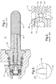
- FIG. 4 illustrates an exemplary embodiment of a valve 100 for a brake control actuator 101 in accordance with aspects of the present invention.
- the valve 100 is depicted in greater visual detail in the circular zoom-in with the same reference numeral shown to the left of valve 100.
- the valve includes a rod 102 operable between respective operating conditions, such as open and closed conditions, to selectively allow passage of brake fluid through the valve.
- the valve comprises a normally-open value. It will be appreciated, however, that the concepts of the present invention are equally applicable independently of whether the valve is operated as a normally open or a normally closed valve.
- the valve further includes a ball 104 affixed at one end of the rod 102.
- the ball includes a sealing section 106 that upon engagement against a ball-receiving seat 108, such as a chamfered seat constructed in the valve, blocks passage to brake fluid that otherwise would pass through an orifice 109.
- the ball further includes a mounting section 110 integral with the sealing section 106.
- the mounting section is configured to provide a reduced footprint relative to a spheroidal footprint, as discussed in the background portion of this specification and as represented by the respective conceptual dashed-arcs, shown in FIGS. 5 through 10.
- the ball configuration enables a strong mechanical joint between the mounting section and the rod since the reduced footprint of the mounting section of the ball, for example, frees relatively more rod structure for effecting the mechanical joint between the ball and the rod.
- the ball 104 may comprise a steel ball, e.g., a chromium alloy steel, affixed onto the rod 102, generally made up of non-magnetic material. It will be appreciated that other alloys including non-metallic materials, such as ceramics, could be used in lieu of a steel ball.
- the desired ball geometry configuring may be achieved through any standard fabrication process that allows removing material from a relatively hard object in a controllable and accurate manner, such as machining, laser cutting, etc.
- the geometry of the ball may be configured using techniques that allow for shaping an object through molding, casting, etc.
- the techniques for affixing the ball to the rod may comprise any standard affixing techniques, such as interference fit, crimping, welding, soldering, bonding, etc.
- FIG. 5 illustrates a valve embodiment corresponding to the assembled actuator arrangement of FIG. 4 wherein the mounting section comprises a pin 120 and the rod includes a bore 122 (FIG. 4) configured to receive the pin.
- FIG. 6 illustrates a valve embodiment wherein the mounting section comprises a bore-defining structure 124 and the rod includes a pin configured to engage the bore-defining structure.
- the embodiment of FIG. 6 is, from a mechanical point of view, the flip side of the embodiment illustrated in FIG. 5. That is, the pin is constructed at the rod end instead of the mounting section of the ball, and the walls of the bore constructed within the ball comprise the mounting section.
- FIG. 7 illustrates a valve embodiment wherein the mounting section comprises a cylindrical section 130 circumferentially defining a midsection of the ball.
- the cylindrical section may be bounded at opposite axial ends thereof by corresponding angled or slanting surfaces, such as surfaces 132 and 134.
- surfaces 132 and 134 advantageously provide such greater mechanical support.
- FIG. 9 illustrates a valve embodiment wherein the mounting section comprises a generally V-shaped notch 136.
- the mounting section may be configured as a hyperboloid 140 defining the midsection of the ball.
- the angular coverage provided by the sealing section of the ball may vary depending on the size of the orifice for passing brake fluid in a given application.
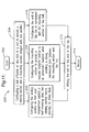
- FIG. 11 illustrates a flow chart illustrating exemplary actions for arranging a valve for a brake control actuator.
- the valve includes a rod 102 (FIG. 4) operable between respective operating conditions to selectively allow passage of brake fluid through the valve.
- the method allows configuring a ball 104 (FIGS. 4-10) affixable at one end of the rod to include a sealing section and a mounting section integral with the sealing section.
- the method allows configuring the sealing section so that upon engagement against a ball-receiving seat, the sealing section blocks passage to brake fluid through the valve orifice.
- the method allows configuring the mounting section to provide a reduced footprint relative to an spheroidal footprint while enabling a strong mechanical joint between the mounting section and the rod.
- the geometrical configurations for the mounting section may include: a pin 120 (FIG. 5); a bore-defining structure 124 (FIG. 6); a cylindrical mounting section 130 (FIG. 7), including slanting surfaces 132 and 134 that bound the cylindrical mounting section (FIG. 8); a V-shaped notch mounting section 136 (FIG. 9); and a hyperboloid mounting section 140 (FIG.
- the end of the rod is configured to correspond with the mounting section of the ball.
- the end of the rod would be configured to provide a suitable mechanical interface with the ball mounting structure prior to a returning action 214, block 212 allows to securely affix the ball to the end of the rod resulting in a strong mechanical joint between the mounting section and the rod.
- block 212 allows to securely affix the ball to the end of the rod resulting in a strong mechanical joint between the mounting section and the rod.
- the parallel layout of the blocks illustrated just prior to block 212 is not meant to limit the invention to any particular sequence since such actions do not have to be performed in parallel sequence.
- the configuring of the end of the rod does not have to be performed in any particular sequence relative to the configuring of the ball since such actions may be independently performed from one another in any desired order that best suits a given manufacturing process flow.
Landscapes
- Engineering & Computer Science (AREA)
- General Engineering & Computer Science (AREA)
- Physics & Mathematics (AREA)
- Mechanical Engineering (AREA)
- Electromagnetism (AREA)
- Fluid Mechanics (AREA)
- Transportation (AREA)
- Magnetically Actuated Valves (AREA)
Abstract
Description
Claims (14)
- A valve 100 for a brake control actuator 101 comprising:a rod 102 operable between respective operating conditions to selectively allow passage of brake fluid through the valve;a ball 104 affixed at one end of the rod, the ball including a sealing section 106 that upon engagement against a ball-receiving seat in the valve blocks passage to brake fluid therethrough, the ball further including a mounting section 110 integral with the sealing section, the mounting section configured to provide a reduced footprint relative to an spheroidal footprint and enable a strong mechanical joint between the mounting section and the rod.
- The valve of claim 1 wherein the mounting section comprises a pin 120 and the rod includes a bore configured to receive the pin.
- The valve of claim 1 wherein the mounting section comprises a bore and the rod includes a pin configured to engage the bore.
- The valve of claim 1 wherein the mounting section comprises a cylindrical section 130 circumferentially defining a midsection of the ball.
- The valve of claim 1 wherein the cylindrical section is bounded at opposite axial ends thereof by corresponding angled surfaces (e.g., 132 and 134).
- The valve of claim 1 wherein the mounting section comprises a generally V-shaped notch 136.
- The valve of claim 1 wherein the mounting section comprises a hyperboloid section 140 defining a midsection of the ball.
- A method for arranging a valve 100 for a brake control actuator 101, the valve including a rod 102 operable between respective operating conditions to selectively allow passage of brake fluid through the valve, the method comprising:configuring (e.g., 204) a ball affixable at one end of the rod, the ball being configured to include a sealing section, and a mounting section integral with the sealing section;configuring (e.g., 206) the sealing section so that upon engagement against a ball-receiving seat, the sealing section blocks passage to brake fluid therethrough;configuring (e.g., 208) the mounting section to provide a reduced footprint relative to an spheroidal footprint while enabling a strong mechanical joint between the mounting section and the rod;configuring (e.g., 210) the end of the rod to correspond with the mounting section of the ball; andaffixing (e.g., 312) the ball to the end of the rod.
- The method of claim 8 wherein the mounting section is configured as a pin and the rod includes a bore configured to receive the pin.
- The method of claim 8 wherein the mounting section is configured to define a bore and the rod includes a pin configured to engage the bore.
- The method of claim 8 wherein the mounting section is configured as a cylindrical section circumferentially defining a midsection of the ball.
- The method of claim 8 wherein the cylindrical section is bounded at opposite axial ends thereof by corresponding angled surfaces.
- The method of claim 8 wherein the mounting section is configured as a generally V-shaped notch.
- The method of claim 8 wherein the mounting section comprises a hyperboloid section defining a midsection of the ball.
Applications Claiming Priority (2)
| Application Number | Priority Date | Filing Date | Title |
|---|---|---|---|
| US974739 | 2001-10-09 | ||
| US09/974,739 US20030067217A1 (en) | 2001-10-09 | 2001-10-09 | Valve and method for a brake control actuator |
Publications (2)
| Publication Number | Publication Date |
|---|---|
| EP1318056A2 true EP1318056A2 (en) | 2003-06-11 |
| EP1318056A3 EP1318056A3 (en) | 2003-10-29 |
Family
ID=25522388
Family Applications (1)
| Application Number | Title | Priority Date | Filing Date |
|---|---|---|---|
| EP02078767A Withdrawn EP1318056A3 (en) | 2001-10-09 | 2002-09-13 | Valve and method for a brake control actuator |
Country Status (2)
| Country | Link |
|---|---|
| US (1) | US20030067217A1 (en) |
| EP (1) | EP1318056A3 (en) |
Cited By (2)
| Publication number | Priority date | Publication date | Assignee | Title |
|---|---|---|---|---|
| FR2872247A1 (en) * | 2004-06-24 | 2005-12-30 | Bosch Gmbh Robert | Solenoid valve for e.g. anti-lock brake system of motor vehicle, has spring device whose support zone is made at level of valve body such that fluid flow arriving in valve chamber across valve seat passes partly on turns of device |
| WO2014206601A1 (en) * | 2013-06-24 | 2014-12-31 | Robert Bosch Gmbh | Pressure control valve having a guide in the valve body |
Families Citing this family (3)
| Publication number | Priority date | Publication date | Assignee | Title |
|---|---|---|---|---|
| JP5857980B2 (en) * | 2013-02-06 | 2016-02-10 | 株式会社日本自動車部品総合研究所 | solenoid valve |
| DE102013220913B4 (en) * | 2013-10-15 | 2025-02-13 | Vitesco Technologies GmbH | valve |
| DE102014217447A1 (en) * | 2014-09-01 | 2016-03-03 | Robert Bosch Gmbh | Valve anchor for a solenoid valve and valve cartridge for a solenoid valve |
Family Cites Families (14)
| Publication number | Priority date | Publication date | Assignee | Title |
|---|---|---|---|---|
| US1763927A (en) * | 1926-07-17 | 1930-06-17 | Nat Refrigeration Corp | Valve |
| US1939128A (en) * | 1929-03-25 | 1933-12-12 | F C Muren | Pump valve |
| US2194961A (en) * | 1938-06-13 | 1940-03-26 | Walker Edward | Valve |
| US2723828A (en) * | 1951-12-07 | 1955-11-15 | John L Edlund | Friction reducing cap for a faucet ball valve |
| CH387405A (en) * | 1961-03-20 | 1965-01-31 | Eldima Ag | Electric valve without gland |
| US3213524A (en) * | 1962-09-21 | 1965-10-26 | Bendix Corp | Method of making a valve poppet construction |
| US3326513A (en) * | 1964-11-10 | 1967-06-20 | Yarway Corp | Means for interconnecting valve members |
| US3857410A (en) * | 1973-05-07 | 1974-12-31 | Sno Trik Co | Switching valve |
| DE2553011A1 (en) * | 1975-11-26 | 1977-06-02 | Gerdts Gustav F Kg | Angle fitting self closing valve - has closing element with magnet armature and surrounding electromagnet for scavenging pipe contents |
| DE3445405A1 (en) * | 1984-12-13 | 1986-06-19 | Robert Bosch Gmbh, 7000 Stuttgart | ELECTROMAGNETICALLY ACTUABLE VALVE |
| DE4037172C2 (en) * | 1990-01-09 | 1999-11-04 | Aweco Kunststofftech Geraete | magnetic valve |
| JP2569208Y2 (en) * | 1992-10-13 | 1998-04-22 | 株式会社ユニシアジェックス | Solenoid valve structure |
| JP3294382B2 (en) * | 1992-10-30 | 2002-06-24 | 株式会社デンソー | Flow control valve |
| DE19805404A1 (en) * | 1998-02-11 | 1999-08-12 | Itt Mfg Enterprises Inc | Pressure control valve |
-
2001
- 2001-10-09 US US09/974,739 patent/US20030067217A1/en not_active Abandoned
-
2002
- 2002-09-13 EP EP02078767A patent/EP1318056A3/en not_active Withdrawn
Cited By (2)
| Publication number | Priority date | Publication date | Assignee | Title |
|---|---|---|---|---|
| FR2872247A1 (en) * | 2004-06-24 | 2005-12-30 | Bosch Gmbh Robert | Solenoid valve for e.g. anti-lock brake system of motor vehicle, has spring device whose support zone is made at level of valve body such that fluid flow arriving in valve chamber across valve seat passes partly on turns of device |
| WO2014206601A1 (en) * | 2013-06-24 | 2014-12-31 | Robert Bosch Gmbh | Pressure control valve having a guide in the valve body |
Also Published As
| Publication number | Publication date |
|---|---|
| US20030067217A1 (en) | 2003-04-10 |
| EP1318056A3 (en) | 2003-10-29 |
Similar Documents
| Publication | Publication Date | Title |
|---|---|---|
| US6877717B2 (en) | Control valve for a vehicular brake system | |
| EP0997363B1 (en) | Supply valve for a hydraulic control unit of a vehicular braking system | |
| JP5335512B2 (en) | Brake hydraulic pressure control device for bar handle vehicle | |
| JPH08230636A (en) | Magnet valve with pressure limiting device for slip-controlled vehicle braking | |
| KR100465201B1 (en) | Solenoid Controlled Valve of Anti-lock Brake System | |
| JP4914521B2 (en) | Magnet valve | |
| US20030183790A1 (en) | Anti-lock brake system solenoid valve | |
| JP2001055132A (en) | Shut-off valve to control fluid flow | |
| US6390444B1 (en) | Two-stage parallel spring solenoid valve | |
| JPH10507813A (en) | Solenoid valve with pressure limiting for slip-controlled automotive braking systems | |
| US5836334A (en) | Electromagnetically actuated valve for slip-controlled hydraulic brake systems in motor vehicles | |
| EP1967778A1 (en) | Biased actuator systems | |
| CN105026813B (en) | Magnetic valve | |
| US20030067217A1 (en) | Valve and method for a brake control actuator | |
| GB2284877A (en) | Electromagnetically operated valve | |
| JPH0259349B2 (en) | ||
| EP1083372B1 (en) | Electromagnetically driving part | |
| US6390570B1 (en) | Vehicle solenoid valve | |
| JP5315911B2 (en) | Electromagnetic valve and electromagnetic valve unit including the same | |
| US6332655B1 (en) | Electromagnetic valve for a hydraulic brake | |
| JP2013212531A (en) | Caulking joint method and caulking joint structure | |
| JP2009233736A (en) | Parts assembly | |
| JP5359000B2 (en) | Parts assembly | |
| CN114962505B (en) | High-speed switch electromagnetic valve | |
| JP2007146914A (en) | Solenoid valve structure and method of manufacturing the same |
Legal Events
| Date | Code | Title | Description |
|---|---|---|---|
| PUAI | Public reference made under article 153(3) epc to a published international application that has entered the european phase |
Free format text: ORIGINAL CODE: 0009012 |
|
| AK | Designated contracting states |
Designated state(s): AT BE BG CH CY CZ DE DK EE ES FI FR GB GR IE IT LI LU MC NL PT SE SK TR |
|
| AX | Request for extension of the european patent |
Extension state: AL LT LV MK RO SI |
|
| PUAL | Search report despatched |
Free format text: ORIGINAL CODE: 0009013 |
|
| AK | Designated contracting states |
Kind code of ref document: A3 Designated state(s): AT BE BG CH CY CZ DE DK EE ES FI FR GB GR IE IT LI LU MC NL PT SE SK TR |
|
| AX | Request for extension of the european patent |
Extension state: AL LT LV MK RO SI |
|
| AKX | Designation fees paid | ||
| REG | Reference to a national code |
Ref country code: DE Ref legal event code: 8566 |
|
| STAA | Information on the status of an ep patent application or granted ep patent |
Free format text: STATUS: THE APPLICATION IS DEEMED TO BE WITHDRAWN |
|
| 18D | Application deemed to be withdrawn |
Effective date: 20040430 |