EP1317127A2 - Image reading apparatus and method of accelerating drive of reading portion thereof - Google Patents
Image reading apparatus and method of accelerating drive of reading portion thereof Download PDFInfo
- Publication number
- EP1317127A2 EP1317127A2 EP02025675A EP02025675A EP1317127A2 EP 1317127 A2 EP1317127 A2 EP 1317127A2 EP 02025675 A EP02025675 A EP 02025675A EP 02025675 A EP02025675 A EP 02025675A EP 1317127 A2 EP1317127 A2 EP 1317127A2
- Authority
- EP
- European Patent Office
- Prior art keywords
- driving
- reading
- speed
- frequencies
- switching point
- Prior art date
- Legal status (The legal status is an assumption and is not a legal conclusion. Google has not performed a legal analysis and makes no representation as to the accuracy of the status listed.)
- Granted
Links
Images



Classifications
-
- H—ELECTRICITY
- H04—ELECTRIC COMMUNICATION TECHNIQUE
- H04N—PICTORIAL COMMUNICATION, e.g. TELEVISION
- H04N1/00—Scanning, transmission or reproduction of documents or the like, e.g. facsimile transmission; Details thereof
- H04N1/04—Scanning arrangements, i.e. arrangements for the displacement of active reading or reproducing elements relative to the original or reproducing medium, or vice versa
- H04N1/047—Detection, control or error compensation of scanning velocity or position
- H04N1/0473—Detection, control or error compensation of scanning velocity or position in subscanning direction, e.g. picture start or line-to-line synchronisation
-
- H—ELECTRICITY
- H04—ELECTRIC COMMUNICATION TECHNIQUE
- H04N—PICTORIAL COMMUNICATION, e.g. TELEVISION
- H04N1/00—Scanning, transmission or reproduction of documents or the like, e.g. facsimile transmission; Details thereof
- H04N1/04—Scanning arrangements, i.e. arrangements for the displacement of active reading or reproducing elements relative to the original or reproducing medium, or vice versa
- H04N1/10—Scanning arrangements, i.e. arrangements for the displacement of active reading or reproducing elements relative to the original or reproducing medium, or vice versa using flat picture-bearing surfaces
- H04N1/1013—Scanning arrangements, i.e. arrangements for the displacement of active reading or reproducing elements relative to the original or reproducing medium, or vice versa using flat picture-bearing surfaces with sub-scanning by translatory movement of at least a part of the main-scanning components
-
- H—ELECTRICITY
- H04—ELECTRIC COMMUNICATION TECHNIQUE
- H04N—PICTORIAL COMMUNICATION, e.g. TELEVISION
- H04N1/00—Scanning, transmission or reproduction of documents or the like, e.g. facsimile transmission; Details thereof
- H04N1/04—Scanning arrangements, i.e. arrangements for the displacement of active reading or reproducing elements relative to the original or reproducing medium, or vice versa
- H04N1/19—Scanning arrangements, i.e. arrangements for the displacement of active reading or reproducing elements relative to the original or reproducing medium, or vice versa using multi-element arrays
- H04N1/191—Scanning arrangements, i.e. arrangements for the displacement of active reading or reproducing elements relative to the original or reproducing medium, or vice versa using multi-element arrays the array comprising a one-dimensional [1D] array
- H04N1/192—Simultaneously or substantially simultaneously scanning picture elements on one main scanning line
- H04N1/193—Simultaneously or substantially simultaneously scanning picture elements on one main scanning line using electrically scanned linear arrays, e.g. linear CCD arrays
-
- H—ELECTRICITY
- H04—ELECTRIC COMMUNICATION TECHNIQUE
- H04N—PICTORIAL COMMUNICATION, e.g. TELEVISION
- H04N2201/00—Indexing scheme relating to scanning, transmission or reproduction of documents or the like, and to details thereof
- H04N2201/024—Indexing scheme relating to scanning, transmission or reproduction of documents or the like, and to details thereof deleted
- H04N2201/02406—Arrangements for positioning elements within a head
- H04N2201/02439—Positioning method
-
- H—ELECTRICITY
- H04—ELECTRIC COMMUNICATION TECHNIQUE
- H04N—PICTORIAL COMMUNICATION, e.g. TELEVISION
- H04N2201/00—Indexing scheme relating to scanning, transmission or reproduction of documents or the like, and to details thereof
- H04N2201/04—Scanning arrangements
- H04N2201/047—Detection, control or error compensation of scanning velocity or position
- H04N2201/04753—Control or error compensation of scanning position or velocity
- H04N2201/04755—Control or error compensation of scanning position or velocity by controlling the position or movement of a scanning element or carriage, e.g. of a polygonal mirror, of a drive motor
-
- H—ELECTRICITY
- H04—ELECTRIC COMMUNICATION TECHNIQUE
- H04N—PICTORIAL COMMUNICATION, e.g. TELEVISION
- H04N2201/00—Indexing scheme relating to scanning, transmission or reproduction of documents or the like, and to details thereof
- H04N2201/04—Scanning arrangements
- H04N2201/047—Detection, control or error compensation of scanning velocity or position
- H04N2201/04753—Control or error compensation of scanning position or velocity
- H04N2201/04793—Control or error compensation of scanning position or velocity using stored control or compensation data, e.g. previously measured data
-
- H—ELECTRICITY
- H04—ELECTRIC COMMUNICATION TECHNIQUE
- H04N—PICTORIAL COMMUNICATION, e.g. TELEVISION
- H04N2201/00—Indexing scheme relating to scanning, transmission or reproduction of documents or the like, and to details thereof
- H04N2201/04—Scanning arrangements
- H04N2201/047—Detection, control or error compensation of scanning velocity or position
- H04N2201/04753—Control or error compensation of scanning position or velocity
- H04N2201/04794—Varying the control or compensation during the scan, e.g. using continuous feedback or from line to line
Definitions
- the present invention generally relates to an image reading apparatus mounted on a copy machine, a printer, a facsimile machine, a scanner, etc., and a method of accelerating the drive of a reading portion of an image reading apparatus.
- the optical unit accelerates while moving from a stop position (home position) to an image reading position to a predetermined speed, and then begins to read in a constant speed from the image reading position.
- a stop position home position
- the optical unit cannot switch smoothly to the constant speed due to inertia caused by the rapid acceleration or deceleration thereof, thereby causing the optical unit to overshoot.
- the optical unit in a case where the optical unit reaches the image reading position before the overshoot is recovered, the optical unit cannot move at a constant speed, thereby creating irregular images such as shaky images, or overlapped images.
- the optical unit in reading with a full color reading apparatus employing an RGB (Red-Green-Blue) tri-linear CCD (Charge Coupled Device) sensor, the optical unit lurches to cause the RGB tri-linear CCD sensor to deviate slightly from an RGB reading position, thereby resulting to problems such as inadvertently coloring both sides of a black line.
- An excessive rapid acceleration being uncontrollable for a torque of the motor causes the motor to lose synchronism, and result to stoppage of the image reading apparatus.
- the invention provides an image forming apparatus, including a reading portion for reading an image by scanning an original document, driving means for driving the reading portion, and memory means for storing therein a plurality of driving frequencies for enabling the driving means to switch to a variety of speeds and drive in a step by step manner, and for storing therein a table indicative of a switching point for switching one driving frequency of the plurality of driving frequencies to another driving frequency of the plurality of driving frequencies, wherein one driving frequency of the plurality of driving frequencies is switched to another driving frequency of the plurality of driving frequencies at the switching point.
- the reading portion of the image reading apparatus comprising a lamp, a mirror, and a carriage for supporting the lamp and the mirror, is formed as a single unit.
- the reading portion having a substantial amount of weight gains speed due to moment of inertia created when the reading portion is driven.
- the reading portion having gained speed will therefore overshoot when slowed down.
- the degree of overshoot increases in association with the increase in the difference between acceleration rate and deceleration rate, and also in association with the increase in the moment of inertia.
- a method of forming a reading portion as light as possible or a method of reducing the driving rate could be introduced for reducing overshoot.
- this invention uses a table indicative of a point for switching one driving frequency of a plurality of driving frequencies to another driving frequency of a plurality of driving frequencies, and determines driving frequency with reference to the table.
- a memory means includes a table indicative of a switching point for switching one driving frequency of the plurality of driving frequencies to another driving frequency of the plurality of driving frequencies, in which one driving frequency of the plurality of driving frequencies is switched to another driving frequency of the plurality of driving frequencies at the switching point, thereby providing consistent prevention of an overshoot with minimal memory capacity.
- the plurality of driving frequencies include a low acceleration driving frequency and a high acceleration driving frequency, wherein the high acceleration driving frequency is switched to the low acceleration driving frequency at the switching point.
- the plural driving frequencies are basically formed by combining 2 types of frequencies. That is, the driving means is first driven with the high acceleration driving frequency, then, the high acceleration driving frequency is switched to the low acceleration driving frequency upon reaching the switching point, and then the low acceleration driving frequency is switched to a constant reading speed upon reaching a prescribed reading speed selected (determined) from a control panel or the like. Accordingly, gradual acceleration can be provided consistently with simple control with a controller (e.g.CPU) by switching the high acceleration driving frequency to the low acceleration driving frequency at the switching point.
- a controller e.g.CPU
- the switching point is determined as a point where the driving means reaches a prescribed driving rate, or as a prescribed elapsed time from an initial drive of the driving means.
- the switching point is a point where the driving means reaches a prescribed driving rate after being started and gradually accelerated. Since speed and time are closely related, the switching point may also be determined as a prescribed time elapsed from the start of the driving means. Accordingly, a precise point for switching the driving rate can be determined since the switching point is defined as a point where a driving rate of the driving means reaches a prescribed rate, or as a prescribed elapsed time from the initial drive of the driving means.
- each driving frequency of the plurality of driving frequencies is predetermined according to a reading speed selected (determined) with a control panel or the like; wherein each driving frequency of the plurality of driving frequencies is predetermined to enable the driving rate of the driving means to accelerate to the reading speed before the reading portion reaches an image reading area after the high acceleration driving frequency is switched to the low acceleration driving frequency at the switching point, wherein each driving frequency of the plurality of driving frequencies is predetermined to prevent the driving means from causing an overshoot.
- Each driving frequency of the plurality of driving frequencies is predetermined according to a reading speed of the image reading apparatus. It is to be noted that each of the driving frequencies is required to be predetermined to enable the driving speed of the driving means to be accelerated to the reading speed before the reading portion reaches an image reading area after the driving frequency is switched from the high acceleration driving frequency to the low acceleration driving frequency at the switching point. In addition, each of the driving frequencies is required to be predetermined to prevent the driving means from causing an overshoot.
- each of the driving frequencies is predetermined for enabling the driving speed of the driving means to accelerate to the reading speed before the reading portion reaches an image reading area after the driving frequency is switched from the high acceleration driving frequency to the low acceleration driving frequency at the switching point, and for preventing the driving means from causing an overshoot.
- the image reading apparatus may include a calculating means for calculating a driving speed of the driving means in correspondence to the reading speed, wherein the switching point is determined according to the result of the calculating means.
- driving frequency is predetermined according to the reading speed of an image reading apparatus with use of a table.
- This case however is not to be restricted to such particular image reading apparatus.
- This case requiring no preparation of tables includes a calculating means for calculating driving rate according to reading speed selected (determined) from a control panel or the like, in which the calculating means calculates driving speed each time for determining the switching point. Since the switching point is determined according to the result of the calculating means, the preparation of a table is not required, thereby providing versatility for various types of image reading apparatuses.
- the driving means is decelerated in an opposite order with respect to acceleration of the driving means by referring to the switching point stored in the table.
- the table used for gradual acceleration has a point for switching driving frequency stored therein.
- the gradual acceleration is performed in the following order: driving in a high rate, switching driving frequency at a switching point, driving in a low rate, driving at reading speed.
- a gradual deceleration is performed in the following order: driving at reading speed, driving at a low rate, switching driving frequency at the switching point, driving in a high speed. Since the table having the switching point included therein can also be used for deceleration by driving the driving means in an opposite order with respect to acceleration, the required number of tables would be minimal, thereby saving memory space for the memory means such as RAM (Random Access Memory) or the like.
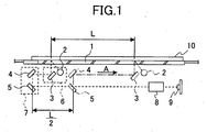
- Fig.1 is a schematic view showing an embodiment of a reading apparatus to which the present invention is applied.
- the reading apparatus has an original document support portion 1 formed of a transparent glass; a lamp 2 for irradiation upon an original document 10 arranged on the original document support portion 1; a first mirror 3, a second mirror 4, and a third mirror 5 for deflecting a reflected image of the original document 10, respectively; a lens 8 for condensing light reflected from each of the mirrors; and a CCD 9 for photo electric transfer of the condensed light; in which the second mirror 4 and the third mirror 5 move a length of L/2 forward in a direction toward A whenever the lamp 2 and the first mirror 3 move a length of L forward, so that the entire original document 10 can be scanned while maintaining a prescribed light path of a prescribed length.
- Fig.2 is a perspective view showing an embodiment of a driving means for explaining a driving system of a reading apparatus to which the present invention is applied.
- a first carriage 6 including the lamp 2 and the first mirror 3 is attached to a driving wire 11.
- a second carriage 7 including the second mirror 4 and the third mirror 5 is connected to a driving wire 11 via a pulley 12 wounded with the driving wire 11.
- the driving wire 11 is wound to a wire pulley 15 connected to a driving axis 14, thereby allowing the drive of a motor 18 to be transmitted via a timing pulley 16 and a timing belt 17.
- the first carriage 6 returns a prescribed length back, that is, returns to a home position after one end of the first carriage 6 passes a home position sensor 13.
- a controller 100 controls the drive of the motor 18 in accordance with a reading speed selected (determined) by a speed selecting means 102 (e.g. control panel).
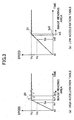
- Fig.3 is a view for explaining a driving pattern for each table, in which (a) indicates a driving pattern for a high acceleration table, and (b) indicates a driving pattern for a low acceleration table.
- the required runway length is indicated as an area Sa in a case where only a high acceleration table is used in acceleration between time t0 and predetermined reading speed Vy.
- reduction of runway length (time ty1) is possible.
- inertia is created to thereby cause an overshoot 20 of the reading portion of the reading apparatus.
- the reading portion of the reading apparatus will reach an image reading area (time tr1) before the overshoot 20 is recovered, thereby adversely affecting the reading image.
- Fig.4 is a view for describing a driving pattern of a first embodiment of this invention.
- the driving means is driven with use of the high acceleration table shown in Fig.3 (a) between start (tO) and speed Vx (tx3), and is then switched to the use of the low acceleration table shown in Fig.3(b) between speed Vx (tx3) and constant speed Vy.
- the driving means Upon reaching time ty3, the driving means is driven at a reading speed of a constant speed. Accordingly, the driving means can accelerate requiring a short acceleration length (time ty3) and with little overshoot 22 by combining the high acceleration table and the low acceleration table as shown in Fig.4.
- the low acceleration table is employed for driving the driving means from ty4 to tx4, and then the high acceleration table is employed for driving the driving means from tx4 to t4. Accordingly, deceleration can also be performed with little overshoot and without the loss of synchronism of the motor by using the tables in an opposite order with respect to acceleration. Not only can the aforementioned combination reduce runway length, but can also shorten the time required for the reading portion to reach the image reading area (time tr3).
- the reading portion of the image reading apparatus comprising a lamp, a mirror, and a carriage for supporting the lamp and the mirror, is formed as a single unit.
- the reading portion having a substantial amount of weight gains speed due to moment of inertia created when the reading portion is driven.
- the reading portion having gained speed will therefore overshoot when slowed down.
- the degree of overshoot increases in association with the increase in the difference between acceleration rate and deceleration rate, and also in association with the increase in the moment of inertia.
- a method of forming a reading portion as light as possible or a method of reducing the driving rate could be introduced for reducing overshoot.
- this invention uses a table indicative of a point for switching one driving frequency of a plurality of driving frequencies to another driving frequency of a plurality of driving frequencies, and determines driving frequency with reference to the table.
- Fig.5 is a view for explaining a second embodiment of this invention regarding a method for accelerating to plural predetermined speeds.
- Fig.6 is a tabulated view for indicating speed ranges and switching points. The second embodiment will be explained hereinafter with reference to Fig.5 and Fig. 6.
- a switching point 29 is "none". Therefore, acceleration is performed only with use of a low acceleration table in a manner shown with a straight line 23 extending from start time t0.
- a driving means is accelerated at a low driving rate from t0 to V0 (tv0), and is changed to a constant reading speed upon reaching a driving speed of V0.
- the switching point 29 is "P1". Therefore, in a manner shown with a straight line 24 extending from start time t0, the driving means is accelerated at a high driving rate until reaching Vp1, and is then switched to a low driving rate in accordance with a low acceleration table at point P1, and is then changed to a constant reading speed upon reaching a driving rate of V1.
- the switching point 29 is "P2". Therefore, in a manner shown with a straight line 25 extending from start time t0, the driving means is accelerated at a high driving rate until reaching Vp2, and is then switched to a low driving rate in accordance with a low acceleration table at point P2, and is then changed to a constant reading speed upon reaching a driving rate of V2.
- the switching point 29 is "P3".
- the driving means is accelerated at a high driving rate until reaching Vp3, and is then switched to a low driving rate in accordance with a low acceleration table at point P3, and is then changed to a constant reading speed upon reaching a driving rate of V3.
- the switching point 29 is "P4".
- the driving means is accelerated at a high driving rate until reaching Vp4, and is then switched to a low driving rate in accordance with a low acceleration table at point P4, and is then changed to a constant reading speed upon reaching a driving rate of V4.
- acceleration can be beneficially performed by combining the high acceleration table and the low acceleration table. Since switching points between low acceleration and high acceleration vary according to reading speed, the switching points are required to be predetermined in correspondence to each reading speed, and are required to be stored into the memory means 101 such as RAM or the like. In determining each point indicated in the table shown in Fig.6, speed 30 and time 31 are stored, and the speed and the time corresponding to each point are then detected, thereby, allowing the driving speed to be switched. In a case where there is room for further control for the controller 100 (e.g.CPU), the switching points may be determined from calculating the driving speed each time according to reading speed.
- the controller 100 e.g.CPU
- Fig.5 tables for 5 kinds of reading speeds including "0 to V0”, “V0 to V1”, “V1 to V2”, “V2 to V3”, and “V3 to V4" would be required unless the high acceleration table and the low acceleration table are used in combination.
- a desired acceleration can be achieved by employing tables of two kinds (a high acceleration table and a low acceleration table) and by storing the table shown in Fig.6 into the memory means 101 such as RAM or the like.
- the tables may be more than two kinds.
- Various tables corresponding to different acceleration rates may also be provided for singular use and for combined use.
Landscapes
- Engineering & Computer Science (AREA)
- Multimedia (AREA)
- Signal Processing (AREA)
- Facsimile Scanning Arrangements (AREA)
- Image Input (AREA)
Abstract
Description
Claims (14)
- An image forming apparatus, comprising:wherein one driving frequency of the plurality of driving frequencies is switched to another driving frequency of the plurality of driving frequencies at the switching point.a reading portion for reading an image by scanning an original document;driving means for driving the reading portion; andmemory means for storing therein a plurality of driving frequencies for enabling the driving means to switch to a variety of speeds and drive in a step by step manner, and for storing therein a table indicative of a switching point for switching one driving frequency of the plurality of driving frequencies to another driving frequency of the plurality of driving frequencies,
- The image reading apparatus as claimed in claim 1, wherein the plurality of driving frequencies include a low acceleration driving frequency and a high acceleration driving frequency, wherein the high acceleration driving frequency is switched to the low acceleration driving frequency at the switching point.
- The image reading apparatus as claimed in claim 1, wherein the switching point is determined as a point where a driving speed of the driving means reaches a prescribed point, or as a prescribed elapsed time from an initial drive of the driving means.
- The image reading apparatus as claimed in claim 1, wherein each driving frequency of the plurality of driving frequencies is predetermined according to a reading speed, wherein each driving frequency of the plurality of driving frequencies is predetermined to enable the driving speed of the driving. means to accelerate to the reading speed before the reading portion reaches an image reading area after the high acceleration driving frequency is switched to the low acceleration driving frequency at the switching point, and wherein each driving frequency of the plurality of driving frequencies is predetermined to prevent the driving means from causing an overshoot.
- The image reading apparatus as claimed in claim 1, wherein the driving means is decelerated with reference to the switching point stored in the table.
- The image reading apparatus as claimed in claim 1, further comprising speed selecting means for selecting a speed range from a plurality of speed ranges of the driving means, wherein the table stored in the memory means is indicative of a plurality of switching points corresponding to the plurality of speed ranges, wherein each switching point of the plurality of switching points is designated to corresponding one of the plurality of speed ranges selected by the speed selecting means.
- An image forming apparatus, comprising:wherein one driving frequency of the plurality of driving frequencies is switched to another driving frequency of the plurality of driving frequencies at the switching point.a reading portion for reading an image by scanning an original document;driving means for driving the reading portion;memory means for storing therein a plurality of driving frequencies for enabling the driving means to switch to a variety of speeds and drive in a step by step manner; andcalculating means for determining a switching point for switching one driving frequency of a plurality of driving frequencies to another driving frequency of the plurality of driving frequencies by calculating a driving speed of the driving means in correspondence to a reading speed,
- A method of accelerating the drive of a reading portion of an image reading apparatus, comprising the steps of:determining a reading speed of the reading portion;determining a switching point; andswitchably driving the reading portion from one driving frequency of a plurality of driving frequencies to another driving frequency of the plurality of driving frequencies, the driving frequency serving to drive a driving means of the reading portion.
- The method as claimed in claim 8, wherein the switching point is determined by selecting the switching point from a table.
- The method as claimed in claim 8, wherein the switching point is determined by calculating the switching point from a reading speed.
- An image forming apparatus, comprising:means for determining a reading speed of a reading portion;means for determining a switching point; andmeans for switchably driving the reading portion from one driving frequency of a plurality of driving frequencies to another driving frequency of the plurality of driving frequencies.
- An image forming apparatus, comprising:wherein one driving frequency of the plurality of driving frequencies is switched to another driving frequency of the plurality of driving frequencies at the switching point.a reading portion for reading an image by scanning an original document;a driving unit configured to drive the reading portion; anda memory unit configured to store a plurality of driving frequencies for enabling the driving unit to switch to a variety of speeds and drive in a step by step manner, and for storing therein a table indicative of a switching point for switching one driving frequency of the plurality of driving frequencies to another driving frequency of the plurality of driving frequencies,
- The image reading apparatus as claimed in claim 12, further comprising a speed selecting unit configured to select a speed range from a plurality of speed ranges of the driving unit, wherein the table stored in the memory unit is indicative of a plurality of switching points corresponding to the plurality of speed ranges, wherein each switching point of the plurality of switching points is designated to corresponding one of the plurality of speed ranges selected by the speed selecting unit.
- An image forming apparatus, comprising:wherein one driving frequency of the plurality of driving frequencies is switched to another driving frequency of the plurality of driving frequencies at the switching point.a reading portion for reading an image by scanning an original document;a driving unit configured to drive the reading portion;a memory unit configured to store therein a plurality of driving frequencies for enabling the driving unit to switch to a variety of speeds and drive in a step by step manner; anda calculating unit configured to determine a switching point for switching one driving frequency of a plurality of driving frequencies to another driving frequency of the plurality of driving frequencies by calculating a driving speed of the driving unit corresponding to a reading speed,
Applications Claiming Priority (2)
| Application Number | Priority Date | Filing Date | Title |
|---|---|---|---|
| JP2001358335A JP3927792B2 (en) | 2001-11-22 | 2001-11-22 | Image reading device |
| JP2001358335 | 2001-11-22 |
Publications (3)
| Publication Number | Publication Date |
|---|---|
| EP1317127A2 true EP1317127A2 (en) | 2003-06-04 |
| EP1317127A3 EP1317127A3 (en) | 2003-06-11 |
| EP1317127B1 EP1317127B1 (en) | 2012-08-01 |
Family
ID=19169529
Family Applications (1)
| Application Number | Title | Priority Date | Filing Date |
|---|---|---|---|
| EP02025675A Expired - Lifetime EP1317127B1 (en) | 2001-11-22 | 2002-11-20 | Image reading apparatus and method of accelerating drive of reading portion thereof |
Country Status (3)
| Country | Link |
|---|---|
| US (1) | US6754463B2 (en) |
| EP (1) | EP1317127B1 (en) |
| JP (1) | JP3927792B2 (en) |
Families Citing this family (5)
| Publication number | Priority date | Publication date | Assignee | Title |
|---|---|---|---|---|
| US7248387B2 (en) * | 2001-07-31 | 2007-07-24 | Umax Data Systems, Inc. | Scanning speed control device and method |
| US7065576B2 (en) * | 2001-09-27 | 2006-06-20 | Matsushita Electric Industrial Co., Ltd. | Dynamic multicast grouping for vehicles and other mobile objects |
| US7522863B2 (en) * | 2006-03-30 | 2009-04-21 | Lexmark International, Inc. | Gear train backlash removal during component acceleration in an image forming device |
| JP7196644B2 (en) | 2019-01-30 | 2022-12-27 | 株式会社リコー | TILT DETECTION DEVICE, READING DEVICE, IMAGE PROCESSING DEVICE, AND TILT DETECTION METHOD |
| JP7131415B2 (en) | 2019-01-31 | 2022-09-06 | 株式会社リコー | TILT DETECTION DEVICE, READING DEVICE, IMAGE PROCESSING DEVICE, AND TILT DETECTION METHOD |
Family Cites Families (15)
| Publication number | Priority date | Publication date | Assignee | Title |
|---|---|---|---|---|
| US4568171A (en) * | 1982-07-05 | 1986-02-04 | Minolta Camera Kabushiki Kaisha | System for controlling the reciprocation of a scanning arrangement |
| JPH03201865A (en) * | 1989-12-28 | 1991-09-03 | Toshiba Corp | Original reader |
| JP3187088B2 (en) | 1991-08-31 | 2001-07-11 | 株式会社リコー | Scanner driving method and apparatus |
| JP3139804B2 (en) * | 1992-01-13 | 2001-03-05 | キヤノン株式会社 | Recording method and apparatus |
| JPH08186690A (en) | 1994-12-28 | 1996-07-16 | Ricoh Co Ltd | Image reader |
| JP3384667B2 (en) * | 1995-01-11 | 2003-03-10 | 株式会社リコー | Electronic equipment |
| JPH0965059A (en) * | 1995-08-25 | 1997-03-07 | Ricoh Co Ltd | Image reader |
| US5805208A (en) * | 1995-09-29 | 1998-09-08 | Eastman Kodak Company | Positioning system timing synchronization |
| JPH1023215A (en) | 1996-07-09 | 1998-01-23 | Brother Ind Ltd | Step motor control device |
| JP3544789B2 (en) * | 1996-07-17 | 2004-07-21 | 株式会社リコー | Traveling body driving device for motor control device and image reading device |
| JP3608646B2 (en) * | 1997-07-18 | 2005-01-12 | 株式会社リコー | Image forming apparatus and intermediate transfer unit used in the apparatus |
| JP2000101791A (en) * | 1998-09-24 | 2000-04-07 | Ricoh Co Ltd | Image forming device |
| JP2000108443A (en) | 1998-10-02 | 2000-04-18 | Copyer Co Ltd | Method for controlling stepping motor and image-forming apparatus using the same |
| JP2000224382A (en) | 1999-01-27 | 2000-08-11 | Ricoh Co Ltd | Scanner driving method |
| US6414461B1 (en) * | 2000-12-21 | 2002-07-02 | Mustek Systems Inc. | Scanner that controls stepping motor torque |
-
2001
- 2001-11-22 JP JP2001358335A patent/JP3927792B2/en not_active Expired - Fee Related
-
2002
- 2002-11-20 US US10/299,718 patent/US6754463B2/en not_active Expired - Lifetime
- 2002-11-20 EP EP02025675A patent/EP1317127B1/en not_active Expired - Lifetime
Also Published As
| Publication number | Publication date |
|---|---|
| US20030095813A1 (en) | 2003-05-22 |
| EP1317127B1 (en) | 2012-08-01 |
| JP3927792B2 (en) | 2007-06-13 |
| US6754463B2 (en) | 2004-06-22 |
| EP1317127A3 (en) | 2003-06-11 |
| JP2003163793A (en) | 2003-06-06 |
Similar Documents
| Publication | Publication Date | Title |
|---|---|---|
| US4748514A (en) | Variable rate scanning control | |
| US6747765B2 (en) | Image reading system | |
| US6754463B2 (en) | Image reading apparatus and method of accelerating drive of reading portion thereof | |
| JPH07212519A (en) | Scanning device | |
| US5095372A (en) | Combined copying machine and facsimile scanner and method | |
| US7274493B2 (en) | Image reading apparatus and image reading method | |
| US20030007816A1 (en) | Image reading apparatus and image reading method | |
| KR101518773B1 (en) | Method for controlling motor in a image reading apparatus | |
| US6510302B1 (en) | Image forming apparatus and method of controlling the apparatus | |
| JP4511258B2 (en) | Image reading device | |
| JP4479544B2 (en) | Image reading device | |
| JP2000253220A (en) | Image reading device | |
| JPH0514609A (en) | Picture processing unit | |
| JP2002259957A (en) | Image reading device and image forming device | |
| JPH0358665A (en) | Picture reader | |
| KR0115460Y1 (en) | Apparatus for controlling movement optical speed of facsimile | |
| JP2002082396A (en) | Image reading device | |
| JPH11298689A (en) | Image reader | |
| JPH04360366A (en) | Picture reader | |
| JP2618508B2 (en) | Image reading device | |
| JPS63151171A (en) | Hand operated scanning type picture reader | |
| JP2000066730A (en) | Drive device and image reading device | |
| JP2001024859A (en) | Image reading apparatus and method, and image forming system | |
| JPH0358668A (en) | Picture reader | |
| JPH0714193B2 (en) | Image reader |
Legal Events
| Date | Code | Title | Description |
|---|---|---|---|
| PUAI | Public reference made under article 153(3) epc to a published international application that has entered the european phase |
Free format text: ORIGINAL CODE: 0009012 |
|
| PUAL | Search report despatched |
Free format text: ORIGINAL CODE: 0009013 |
|
| 17P | Request for examination filed |
Effective date: 20021120 |
|
| AK | Designated contracting states |
Designated state(s): AT BE BG CH CY CZ DE DK EE ES FI FR GB GR IE IT LI LU MC NL PT SE SK TR |
|
| AX | Request for extension of the european patent |
Extension state: AL LT LV MK RO SI |
|
| AK | Designated contracting states |
Designated state(s): AT BE BG CH CY CZ DE DK EE ES FI FR GB GR IE IT LI LU MC NL PT SE SK TR |
|
| AX | Request for extension of the european patent |
Extension state: AL LT LV MK RO SI |
|
| RIN1 | Information on inventor provided before grant (corrected) |
Inventor name: TAKAHASHI, TAKUJI Inventor name: NAGAO, YOSHIAKI Inventor name: NISHIKINO, SACHIKO |
|
| AKX | Designation fees paid |
Designated state(s): DE FR GB |
|
| 17Q | First examination report despatched |
Effective date: 20081128 |
|
| GRAP | Despatch of communication of intention to grant a patent |
Free format text: ORIGINAL CODE: EPIDOSNIGR1 |
|
| GRAS | Grant fee paid |
Free format text: ORIGINAL CODE: EPIDOSNIGR3 |
|
| GRAA | (expected) grant |
Free format text: ORIGINAL CODE: 0009210 |
|
| AK | Designated contracting states |
Kind code of ref document: B1 Designated state(s): DE FR GB |
|
| REG | Reference to a national code |
Ref country code: GB Ref legal event code: FG4D |
|
| REG | Reference to a national code |
Ref country code: DE Ref legal event code: R096 Ref document number: 60243403 Country of ref document: DE Effective date: 20120927 |
|
| PLBE | No opposition filed within time limit |
Free format text: ORIGINAL CODE: 0009261 |
|
| STAA | Information on the status of an ep patent application or granted ep patent |
Free format text: STATUS: NO OPPOSITION FILED WITHIN TIME LIMIT |
|
| 26N | No opposition filed |
Effective date: 20130503 |
|
| REG | Reference to a national code |
Ref country code: DE Ref legal event code: R097 Ref document number: 60243403 Country of ref document: DE Effective date: 20130503 |
|
| REG | Reference to a national code |
Ref country code: FR Ref legal event code: PLFP Year of fee payment: 14 |
|
| REG | Reference to a national code |
Ref country code: FR Ref legal event code: PLFP Year of fee payment: 15 |
|
| REG | Reference to a national code |
Ref country code: FR Ref legal event code: PLFP Year of fee payment: 16 |
|
| PGFP | Annual fee paid to national office [announced via postgrant information from national office to epo] |
Ref country code: DE Payment date: 20181120 Year of fee payment: 17 |
|
| PGFP | Annual fee paid to national office [announced via postgrant information from national office to epo] |
Ref country code: FR Payment date: 20181123 Year of fee payment: 17 Ref country code: GB Payment date: 20181120 Year of fee payment: 17 |
|
| REG | Reference to a national code |
Ref country code: DE Ref legal event code: R119 Ref document number: 60243403 Country of ref document: DE |
|
| GBPC | Gb: european patent ceased through non-payment of renewal fee |
Effective date: 20191120 |
|
| PG25 | Lapsed in a contracting state [announced via postgrant information from national office to epo] |
Ref country code: GB Free format text: LAPSE BECAUSE OF NON-PAYMENT OF DUE FEES Effective date: 20191120 Ref country code: DE Free format text: LAPSE BECAUSE OF NON-PAYMENT OF DUE FEES Effective date: 20200603 Ref country code: FR Free format text: LAPSE BECAUSE OF NON-PAYMENT OF DUE FEES Effective date: 20191130 |