EP1316804B1 - Method of displaying calibration parameters of an apparatus having ports for testing a device, and corresponding apparatus - Google Patents
Method of displaying calibration parameters of an apparatus having ports for testing a device, and corresponding apparatus Download PDFInfo
- Publication number
- EP1316804B1 EP1316804B1 EP02257253A EP02257253A EP1316804B1 EP 1316804 B1 EP1316804 B1 EP 1316804B1 EP 02257253 A EP02257253 A EP 02257253A EP 02257253 A EP02257253 A EP 02257253A EP 1316804 B1 EP1316804 B1 EP 1316804B1
- Authority
- EP
- European Patent Office
- Prior art keywords
- parameters
- calibration
- displaying
- displayed
- error correction
- Prior art date
- Legal status (The legal status is an assumption and is not a legal conclusion. Google has not performed a legal analysis and makes no representation as to the accuracy of the status listed.)
- Expired - Lifetime
Links
- 238000000034 method Methods 0.000 title claims abstract description 110
- 238000012360 testing method Methods 0.000 title claims description 13
- 238000012937 correction Methods 0.000 claims abstract description 137
- 239000011159 matrix material Substances 0.000 claims abstract description 12
- 238000005259 measurement Methods 0.000 abstract description 66
- 230000004044 response Effects 0.000 description 16
- 238000012545 processing Methods 0.000 description 6
- 230000005540 biological transmission Effects 0.000 description 4
- 238000010586 diagram Methods 0.000 description 2
- 238000005516 engineering process Methods 0.000 description 1
- 230000006870 function Effects 0.000 description 1
- 238000012856 packing Methods 0.000 description 1
Images


Classifications
-
- G—PHYSICS
- G01—MEASURING; TESTING
- G01R—MEASURING ELECTRIC VARIABLES; MEASURING MAGNETIC VARIABLES
- G01R13/00—Arrangements for displaying electric variables or waveforms
- G01R13/20—Cathode-ray oscilloscopes
-
- G—PHYSICS
- G01—MEASURING; TESTING
- G01R—MEASURING ELECTRIC VARIABLES; MEASURING MAGNETIC VARIABLES
- G01R27/00—Arrangements for measuring resistance, reactance, impedance, or electric characteristics derived therefrom
- G01R27/28—Measuring attenuation, gain, phase shift or derived characteristics of electric four pole networks, i.e. two-port networks; Measuring transient response
-
- G—PHYSICS
- G01—MEASURING; TESTING
- G01R—MEASURING ELECTRIC VARIABLES; MEASURING MAGNETIC VARIABLES
- G01R35/00—Testing or calibrating of apparatus covered by the other groups of this subclass
- G01R35/005—Calibrating; Standards or reference devices, e.g. voltage or resistance standards, "golden" references
Abstract
Description
- The present invention relates to a method for displaying the measurement conditions on a measurement device. More specifically, the invention relates to the display of information related to error correction, namely, the correction conditions. The display method of the present invention is suited for use in a measurement device equipped with a plurality of ports.
- A measurement device is rarely in the ideal state for the entire apparatus and generally differences develop between the measurements and the true values. These differences, namely the causes of the measurement errors, have reproducibility and predictability over some time span or some temperature range. The measurement errors based on these causes can be removed and the measurement device is calibrated. In order to remove these measurement errors, a network analyzer, which is a measurement device, is calibrated based on measurements such as the thru, open, short, and high-precision load impedance, which are well-known electrical standards. Thus, the network analyzer can correct the measurements and display measurement results close to the true values.
- A network analyzer has calibration methods such as response calibration and full N-port calibration, where N is a natural number. Each calibration method has various features such as the measurement accuracy and the measurement time. The user adopts a calibration method while considering these features. It would be convenient if the user could determine how to error correct the S-parameters during the measurement, that is, how to measure the measurement errors of the S-parameters beforehand by some calibration method and correct the measurements, because the user can judge whether or not the values of the S-parameters to be measured are valid. Therefore, a conventional network analyzer has a function to display various calibration methods applied to the S-parameters to be measured on the screen for displaying the measurement results.
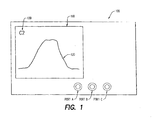
- Fig. 1 is a front view of a conventional network analyzer. In Fig. 1, the
network analyzer 100 is a 3-port network analyzer equipped with ports A, B, and C for connecting to the device under test α (not shown) and measuring the reflection coefficient and propagation coefficient and ascreen 110 for displaying the measurement conditions and the measurement results. - The
trace 120, which is an S-parameter measurement, and thesymbol 130 indicating the correction method are displayed on thescreen 110. - The
symbol 130 is "C1" when the measured S-parameters are corrected by response calibration or full 1-port calibration, "C2" when corrected by full 2-port calibration, and "C3" when corrected by full 3-port calibration. Consequently, ifsymbol 130 displays "C2" as shown in Fig. 1, the user can know that the S-parameters are corrected by full 2-port calibration during measurement. If the user cannot connect the device under test to two ports and cannot conduct the measurements, correct error correction is not performed. - However, the displayed calibration method is only a simple symbol display, which is inconvenient when the ports used during measurement are specified. This inconvenience is obvious when an unspecified number of users share the network analyzer.
- For example, when the
network analyzer 100 in this example is used and the reflection coefficient S22 is measured at port B, whether the combination of measurement ports targeted by full 2-port calibration is the port B and port A group or the port B and port C group cannot be determined by only knowing thesymbol 130. Thus, if which ports were used and what kind of calibration method was applied cannot be determined during calibration, the user must verify the calibration methods of the other S-parameters and must specify the port group that should be used in the measurements. When using a conventional network analyzer, the traces of the S-parameters must be displayed in order to verify the calibration methods for the S-parameters, which is a nuisance. In addition, this specification task becomes complex as the number of ports of the network analyzer becomes large. When a plurality of calibration methods coexists and is applied, this task is extremely difficult. - An example of such a conventional analyser is disclosed in the "User's Guide Agilent Technologies 8712ES and 8714ES RF Network Analyzers".
- Therefore, the network analyzer should provide a method that easily determines information related to the error correction of the S-parameters, that is, the correction conditions.
- The problem of the present invention is to solve the problems of the prior art described above. An aim of the invention is to enable the user to easily determine the parameter correction conditions by concurrently displaying the calibration states of the parameters measurable by the measurement device on the display means.
- A further aim is to prevent the incorrect connection of the device under test by displaying the ports used to apply correct error correction to the parameters.
- A further aim is to prevent errors in the measurement operation by the user by displaying the enabled state for parameter correction.
- A further aim is to reduce the effort expended by the user to determine the correction conditions by displaying the correction conditions regardless of how the parameter traces are displayed.
- According to the present invention there is provided a method of displaying parameter correction conditions as defined in
claim 1 and a determination apparatus as defined in claim 7. - A first embodiment of the invention is a method for displaying the parameter correction conditions on the measurement device equipped with ports for connecting to the devices under test in order to measure the parameters and display means, wherein the correction conditions are read from the memory means storing the correction conditions, and the calibration states of all of the parameters are displayed concurrently on the display means related to the ports used in parameter measurement in order to clearly show the parameters calibrated by the calibration method having calibration enabled in the parameter error correction and the other parameters not subjected to the calibration enabled in the parameter error correction for all of the parameters measurable by the measurement device with reference to the read-out correction conditions.
- A second embodiment of the invention is a method for displaying the parameter correction conditions on a measurement device comprised of ports for connecting to the devices under test in order to measure the parameters and display means, wherein the correction conditions are read from the memory means storing the correction conditions, and the calibration states of all of the parameters are displayed concurrently on the display means related to the ports used in parameter measurement in order to clearly show the parameters calibrated by the calibration method having calibration enabled in the parameter error correction and the other parameters not subjected to the calibration enabled in the parameter error correction for the parameters to be measured and all of the parameters to be calibrated by the parameter calibration method with reference to the read-out correction conditions.
- Furthermore, a third embodiment of the invention concurrently displays in a matrix format on the display means during concurrent display on the display means in the first or second embodiment of the invention.
- Furthermore, a fourth embodiment of the invention displays the parameters to be measured on the display means related to the ports used in parameter measurement in the first, second, or third invention.
- Furthermore, a fifth embodiment of the invention displays the ports used for applying correct error correction when error correction is enabled for the parameters to be measured and the ports used in parameter measurement when error correction is disabled on the display means in the first, second, third, or fourth embodiments.
- Furthermore, a sixth embodiment of the invention lists all of the parameters to be calibrated by the parameter calibration method when error correction is enabled from the parameters to be measured in the first, second, third, fourth, or fifth embodiment, and displays the enabled corrections for the listed parameters on the display means related to the ports used in parameter measurement.
- Furthermore, a seventh embodiment of the invention is a method for displaying the parameter correction conditions on the measurement device equipped with ports for connecting to the devices under test in order to measure the parameters and the display means, wherein the correction conditions of the parameters to be measured are read out from the memory means storing the correction conditions, and the read out correction conditions are referenced and displayed on the display means related to the calibration method of the parameters to be measured and the ports used to apply the calibration method.
-
- Fig. 1 is a front view of a conventional network analyzer;
- Fig. 2 is a front view of the network analyzer displaying the correction conditions by using the method of the present invention;
- Fig. 3 shows an example of the display of the screen that is the first embodiment of the method of the present invention;
- Fig. 4 shows the configuration of the network analyzer that displays the correction conditions by using the method of the present invention;
- Fig. 5A shows the format of an information block;
- Fig. 5B shows an example of a plurality of information blocks;
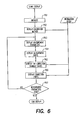
- Fig. 6 shows the display procedure of the correction conditions in the first embodiment using the method of the present invention;
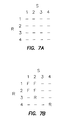
- Fig. 7A shows a display example of the correction conditions in the first embodiment using the method of the present invention;
- Fig. 7B shows a display example of the correction conditions in the first embodiment using the method of the present invention;
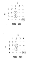
- Fig. 7C shows a display example of the correction conditions in the first embodiment using the method of the present invention;
- Fig. 7D shows a display example of the correction conditions in the first embodiment using the method of the present invention;
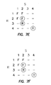
- Fig. 7E shows a display example of the correction conditions in the first embodiment using the method of the present invention;
- Fig. 7F shows a display example of the correction conditions in the first embodiment using the method of the present invention;
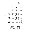
- Fig. 7G shows a display example of the correction conditions in the second embodiment using the method of the present invention;
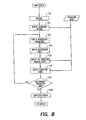
- Fig. 8 is a flow diagram of the display procedure of the correction conditions in the second embodiment using the method of the present invention;
- Fig. 9 shows a display example of the correction conditions in the third embodiment using a method not forming part of the present invention; and
- Fig. 10 shows the display procedure of the correction conditions in the third embodiment.
- The present invention is described with reference to the embodiments shown in the attached drawings.
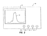
- Fig. 2 is a front view of a network analyzer displaying information related to error correction, that is, the correction conditions, according to the present invention. In Fig. 2, the
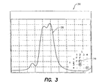
network analyzer 200 is comprised ofport 1,port 2,port 3, andport 4 for connecting to the devices under test, and ascreen 210 for displaying the measurement conditions and the measurement results, and is a 4-port network analyzer capable of measuring the reflection coefficients at each port and the transmission coefficients between the ports. Thetrace 220, which is the S-parameter measurement, and the symbol 230 (see Fig. 3) indicating the calibration method are displayed on thescreen 210. The reflection coefficient of each port and the transmission coefficient between the ports are generally called S-parameters. The S-parameters append two numbers to the letter S. These numbers indicate the send port and the receive port used to measure the S-parameter. For example, S11 indicates the reflection coefficient obtained when the measurement signal is transmitted fromport 1 and the measurement signal is received atport 1. S21 indicates the transmission coefficient obtained when the measurement signal is transmitted fromport 1, and the measurement signal is received atport 2. - The first embodiment shown in Fig. 3 is the
screen 210 displaying the correction conditions according to the method of the present invention. The features of this display example are symbol 230 indicates which calibration method is the basis of the error correction applied to the S-parameters and concurrently displays the symbols related to all of the S-parameters measurable by the network analyzer on thescreen 210. Furthermore, another feature of the invention is to jointly use with a highlighted display such as bold characters to display the enable states of the corrections and to indicate the ports the user should use in order to perform correct error correction of the S-parameters to measure the desired S-parameters - In other words, the applied calibration methods are displayed in a 4 x 4 matrix for the 16 S-parameters measured by a 4-port network analyzer. The column indicates the number of the send port related to each S-parameter. The row indicates the number of the receive port related to each S-parameter. For example, the symbol "F" displayed in
row 1 andcolumn 1 means that S11 was calibrated by the full port calibration method. The symbol "R" displayed inrow 3 andcolumn 2 means that S32 was calibrated by the response calibration method. The symbol "-" displayed inrow 1 andcolumn 4 means that the calibration enabled in the error correction of S14 is not applied. Since S22 is corrected by full port calibration, and S11, S12, and S21 are calibrated by full port calibration, the calibration is performed by full 2-port calibration applied to theport 1 andport 2 group. - The symbol R displayed in
row 3 andcolumn 2 is highlighted as a bold character. This means that the error correction of S32 is enabled. Furthermore,character 1 andcharacter 2 of the send port and the receive port are highlighted and displayed in bold characters. This indicates the ports that should connect to the device under test in order to perform correct error correction when measuring S22. In this case, the indication is the device under test must be connected toport 1 andport 2. The symbols related to S22, S32, and S44 are circled, highlighted, and displayed. This means that these S-parameters are the measurement targets. - Fig. 4 shows the configuration of the
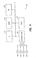
network analyzer 200 for implementing the display of these correction conditions. In Fig. 4, thenetwork analyzer 200 is comprised of aCPU 410; amemory 420, which is the memory means; ameasurement device 430; adisplay 440, which is the display means; and a hard disk drive (HDD) 450, which is the recording medium. - The
CPU 410 controls themeasurement device 430 and thedisplay 440 by executing the program for displaying the correction conditions read out from theHDD 450, and displays the correction conditions on thescreen 210. - The
memory 420 saves the S-parameter correction conditions. The correction conditions are stored in one information block comprised of the applied calibration method, the port numbers used in the execution of the calibration method, and the enable states of the corrections by the calibration method. Fig. 5A shows the format of the information block. In Fig. 5A, CAL is the variable indicating the type of applied calibration method and stores information indicating either open response calibration (RO), short response calibration (RS), thru response calibration (RT), full 1-port calibration (F1), full 2-port calibration (F2), full 3-port calibration (F3), or full 4-port calibration (F4). ENBL is the variable indicating the correction enabled state and stores information indicating either correction enabled (ON) or disabled (OFF) for the S-parameters to be calibrated. PORT is the variable indicating the port numbers used in the calibration and stores the port numbers for only the number of ports used in the calibration. When response calibration was performed, first the receive port and then the send port are stored. For example, if full 2-port calibration was performed onport 1 andport 2, thenumbers number 3 and then thenumber 2 are stored. - The information blocks exist in
memory 420 only for the number of applied calibrations. Fig. 5B is an example when there are three information blocks. In Fig. 5B, thefirst information block 501 indicates that full 2-port calibration is applied toport 1 andport 2, and error correction is enabled for S11, S12, S21, and S22 based on the errors obtained by this calibration. Next, the second information block 502 indicates that thru response calibration is applied to S32 and error correction is enabled for S32 based on the error obtained by this calibration. Next, thethird information block 503 indicates that open response calibration is applied to S44 and error correction is disabled for S44. The error of each S-parameter is measured by a unique calibration method. Consequently, for the 4-port network analyzer in this example, the maximum number of information blocks coexists when response calibration was applied to each S-parameter. The number of information blocks in this case is 16. - The
measurement device 430 is equipped withports -
Display 440 is equipped with ascreen 210, is controlled by theCPU 440, and displays the measurement results and the correction conditions. -
HDD 450 records the program used by thenetwork analyzer 200 to display the correction conditions. - In the above configuration, the processing steps of the program used by the
network analyzer 200 to display the correction conditions on thescreen 210 are illustrated in the flow chart shown in Fig. 6. Figs. 7A to 7F, which are referenced, are the drawings showing a part of thescreen 210. - In Fig. 6, step P61 initializes the region displaying the correction conditions. The 4 x 4 matrix with the symbol "-" in all of the elements is displayed. The rows and columns of the matrix are displayed in order of 1 to 4 to indicate the row number and the column number. "R" that indicates the receive ports is displayed in the rows, and "S" that indicates the send ports is displayed in the columns. Fig. 7A shows the correction conditions in this case. Then the process advances to step P62.
- In step P62, the applied calibration method is displayed as a symbol on the screen related to the ports used in the calibration. The displayed symbols are the contents of the CAL variable, namely, the type of applied calibration method, are successively read out from all of the information blocks. The displayed symbol is the symbol "R" if the content is the response calibration method and the symbol "F" if the full N-port calibration method, where N is an integer from 1 to 4. The display location of the symbol is set by the S-parameter to be calibrated. Specifically, the contents of the PORT variable are referenced from the information block. All of the S-parameters to be calibrated are listed, and specified by the send port and receive port needed to measure each S-parameter. For example, if
information block 1 in Fig. 5B is referenced, the CAL variable indicates full 2-port calibration, and two port numbers are fetched from the PORT variable. Next, all of the S-parameters to be calibrated based on the fetched port numbers are listed. In other words, S11, S12, S21, and S22 are listed. Thus, the symbol "F" is displayed in the four elements ofrow 1,column 1;row 1,column 2;row 2,column 1; androw 2,column 2. - If
information block 2 in Fig. 5 is referenced, CAL variable indicates thru response calibration, and two port numbers are fetched from the PORT variable. Next, the S-parameters calibrated based on the fetched port numbers are listed. In other words, S32 is listed. Thus, the symbol "R" is displayed inrow 3,column 2. For all of the information blocks shown in Fig. 5B, the correction conditions are displayed as shown in Fig. 7B when the process of this step was performed. Then the process advances to step P63. - The processes from step P63 to step P67 select each S-parameter to be measured and perform the process.
- In step P63, the symbols related to the S-parameters to be measured are circled and highlighted to indicate that the S-parameter will be measured. Let S22, S32, and S44 be the measured S-parameters. If the process of this step is performed for all of the information blocks shown in Fig. 5B, the correction conditions are displayed as shown in Fig. 7C. Then the process advances to step P64.
- In step P64, the number of the send port and the number of the receive port used to measure the S-parameters to be measured are displayed as bold characters and highlighted. Let S22, S32, and S44 be the measured S-parameters. If the processing until this step was performed on all of the information blocks shown in Fig. 5B, the correction conditions are displayed as shown in Fig. 7D. Then the process advances to step P65.
- In step P65, if the S-parameters to be measured arc calibrated by any calibration method and correction is enabled, the enabled corrections of the S-parameters are displayed. At this time, the enabled corrections are displayed for all of the S-parameters to be calibrated by the S-parameter calibration method. Specifically, the CAL variable and PORT variable are successively read out from all of the information blocks with the ENBL variable set to ON, and the information blocks containing the S-parameters to be measured in the calibration targets are searched for.
- The CAL variable and PORT variable from the found information blocks are referenced, and all of the S-parameters to be calibrated are listed. All of the symbols related to the listed S-parameters are displayed and highlighted as bold characters. Let S22, S32, and S44 be the measured S-parameters. If the process of this step is applied to all of the information blocks shown in Fig. 5B, the correction conditions are displayed as shown in Fig. 7E.
- In step P66, the send port and receive port used in measuring the S-parameters related to the symbols displayed as bold characters are highlighted as bold characters and displayed. The send port and the receive port are generally called the correction ports. Let S22, S32, and S44 be the measured S-parameters. If the processing up to this step is applied to all of the information blocks shown in Fig. 5B, the correction conditions are shown in Fig. 7F. Then the process advances to step P67.
- In step P67, a new S-parameter to be measured is selected and the process advances to step P62. If there is no S-parameter that can be selected, the processes from step P63 to step P66 are finished for all of the measurable S-parameters, and this display process ends.
- According to the procedure described above, the correction conditions are displayed on the screen of the network analyzer. The features of each step are as follows. Based on the processes in step 61 and step 62, the correction conditions are read out from the memory. Then the calibration states of all of the S-parameters are displayed concurrently on the
screen 210 related to the ports used in S-parameter measurement in order to clearly show the S-parameters calibrated by the calibration method having calibration enabled in the S-parameter error correction and the other S-parameters not subjected to the calibration enabled in the S-parameter error correction for all of the S-parameters measurable by the network analyzer with reference to the information blocks. In step 63, the S-parameters to be measured are displayed on thescreen 210 related to the ports used in measuring the S-parameters. Furthermore, based on the processes in step 64 and step 66, the ports used to apply correct error correction when error correction is enabled for the S-parameters to be measured and the ports used in the S-parameter measurement when error correction is disabled are displayed on thescreen 210. The process in step 65 lists all of the S-parameters to be calibrated by the calibration method for the S-parameters when error correction is enabled for the S-parameters to be measured. The enabled corrections for the listed parameters are displayed on thescreen 210 related to the ports used in S-parameter measurement. - The user looks at the display based on the above procedure and can determine in a glance which calibrations were applied to all of the S-parameters measured by the network analyzer. The S-parameters to be measured, the enable states for S-parameter correction, and the ports that should be used to correctly perform the S-parameter error correction can similarly be determined in a glance. Consequently, the user can easily determine a great deal of information related to S-parameter error correction.
- The second embodiment in Fig. 7G is a portion of the
screen 210 displaying the correction conditions according to the method of the present invention. A feature of this display example is that the correction conditions finally displayed in the first embodiment are limited to the correction conditions related to the S-parameters to be measured and the S-parameters to be calibrated by the parameter calibration method. - The second embodiment displays the correction conditions by adding one more step to the flow chart shown in Fig. 6 for the same configuration as the first embodiment shown in Fig. 4. In the second embodiment, the processing steps of the program used by the
network analyzer 200 to display the correction conditions on thescreen 210 are presented below by using the flow chart shown in Fig. 8. - The processes in step P61 to step P67 in Fig. 8 have already been explained in the first embodiment. However, after the process in step P67 ends, the process advances to the newly added step P68.
- In step 68, the displayed matrix is compressed. Specifically, the rows and columns containing the symbols displayed as bold characters or circled symbols remain. The other rows and columns are deleted. Furthermore, space can be deleted by packing the rows and columns to compress the entire matrix, then the matrix is displayed.
- The display of the correction conditions according to the second embodiment concurrently displays the calibration states of the S-parameters to be measured and the S-parameters to be calibrated by the parameter calibration method on the
screen 210 related to the ports used in the S-parameter measurement. Therefore, the display area can be reduced compared to the first embodiment. - The display examples described previously can be modified if the correction conditions of the S-parameters are concurrently displayed. Several examples are presented below.
- For example, the character highlighting means can use colored characters instead of using bold characters or circling if the differences can be recognized when one character is compared to another character. The send ports can be assigned to the rows and the receive ports to the columns. Furthermore, the matrix can be rotated by any angle and displayed. In addition, the correction conditions can be displayed by using diagrams and are not limited to symbols and numbers in the matrix display.
- The third embodiment in Fig. 9 is the
screen 210 displaying the correction conditions according to a method not forming part of the present invention. In Fig. 9, thescreen 210 is provided with aregion 240 for displaying the measurement results of the S-parameters. Tr1 and Tr2 shown in Fig. 9 represent the traces. S32 and S22 represent the S-parameters to be measured. The numbers displayed to the right of S32 and S22 are the measurements of the S-parameters. The features of this display example are representing the calibration method applied to the S-parameters by thesymbol 250 when the error correction is enabled for the S-parameters to be measured, and displaying thegroup 260 of ports that should be used by the user to correctly perform the error correction of the S-parameters. -
Symbol 250 is displayed when error correction is enabled for the S-parameters to be measured. The symbol indicating the open response calibration (RO), short response calibration (RS), thru response calibration (RT), full 1-port calibration (F1), full 2-port calibration (F2), full 3-port calibration (F3), or full 4-port calibration (F4) is displayed. Thegroup 260 of ports displays the group of ports that should be used by the user in order to correctly perform the error correction of the S-parameters to be measured. - The processing steps of the display program for the
network analyzer 200 having the same configuration as the first embodiment shown in Fig. 4 to display the correction conditions on thescreen 210 are presented below by using the flow chart shown in Fig. 10. - In Fig. 10, the processes from step P71 to step P73 select one S-parameter to be measured and apply the processing.
- In step P71, if the S-parameters to be measured are calibrated by any calibration method and correction is enabled, the calibration methods applied to the S-parameters are displayed. Specifically, the contents of the CAL variable and the PORT variable are successively read from all of the information blocks having the ENBL variable set to ON. The information blocks containing S-parameters to be measured as the calibration targets are searched for. The CAL variable is referenced from the found information blocks and the calibration method is displayed.
- If the S-parameters to be measured are calibrated by any calibration method and have corrections enabled in step P72 and step P71. the group of ports used when applying the S-parameter calibration method, that is, the correction ports, is displayed. Specifically, the CAL variable is referenced from the information blocks found above, and the calibration method is displayed.
- In step P73, a new S-parameter to be measured is selected, and the process advances to step P71. If there are no S-parameters that can be selected, this display process ends because the processes in step P71 and step P72 have finished for all of the measurable S-parameters.
- The display of the correction conditions according to the third embodiment can reduce the display area compared to the second embodiment for display on the
screen 210 related to the calibration methods of the S-parameters to be measured and the ports used to apply the calibration methods. - If the programs shown in Figs. 6, 8, and 10 are recorded on the recording medium so that the measurement device can execute the programs, the recording medium can be installed in the measurement device and can be provided separately from the measurement device.
- For example, the programs are stored on a recording medium such as a CD-ROM, floppy disk, compact flash memory, or externally connected HDD that can be attached to and detached from the measurement device, and can be loaded from these recording media to the measurement device. The programs can be recorded on the ROM provided in the network analyzer and loaded on the measurement device.
- The objective of the present invention is to concurrently display the calibration states of the parameters measurable by the measurement device on the display means to enable the user to easily determine the parameter correction conditions.
- The ports used to apply the correct error correction to the parameters are displayed; therefore, incorrect connections to the devices under test can be prevented.
- Furthermore, the enable states of the parameter corrections are displayed, and operational errors by the user when measuring can be prevented. And regardless of the trace display of the parameters, the correction conditions are displayed. Therefore, the effort expended by the user to determine the correction conditions can be reduced.
Claims (12)
- A method of displaying parameter correction conditions in a determination apparatus (200) having ports (1, 2, 3, 4) to which a device under test is connected in order to determine parameters, a display means (210, 440), and a memory means (420), comprising:reading said correction conditions of said parameters from said memory means storing said correction conditions; anddisplaying a method of calibration used in calibrating said parameters and said ports used for said calibration method in association with each other on said display means, with reference to said read correction conditions characterised in that the method further comprises displaying a calibration enablement state for each of said parameters subject to determination, and for each of said parameters subject to calibration for error correction, and port information used in determination of said parameters, all at once in relationship to each other on said display means,
and wherein each of said calibration enablement states indicates that error correction of each of said parameters is either enabled or disabled. - The method of claim 1 comprising displaying said calibration enablement states for all of said parameters measurable by said determination apparatus.
- The method of claim 1 or claim 2, wherein said parameters displayed on said display means are displayed in matrix form.
- The method of any preceding claim, further comprising displaying port information used in determination of said parameters in association with each of said parameters, wherein port information for conducting proper error correction is displayed when an error correction of said parameters is enabled and said port information used in determination of said parameters is displayed when said error correction of said parameters is disabled.
- The method of any preceding claim, further comprising:enumerating said parameters when said error correction of said parameters is enabled ; anddisplaying the port used in determination of said parameters in association with said enumerated parameters on said display means.
- The method of any preceding claim, wherein said determination apparatus is a network analyser and said parameters are S parameters.
- A determination apparatus (200) having ports (1, 2, 3, 4) connected to a device under test and executing a program embodied on a storage media (450), said program including program instructions for displaying parameter correction conditions in order to determine parameters, a display means (210, 440), and a memory means (420), said program comprising:program instructions for reading said correction conditions of said parameters from said memory means storing said correction conditions; and program instructions for displaying a method of calibration used in calibrating said parameters and said ports used for said calibration method in association with ach other on said display means, with reference to said read correction condition
characterised in that said program instructions further include instructions for displaying a calibration enablement state for each of said parameters subject to determination and for each of said parameters subject to calibration for error correction, and port information used in determination of said parameters, all at once in relations, to each other on said display means,
and wherein each of said calibration enablement states is indicative that error correction of each of said parameters is either enabled or disabled. - The determination apparatus of claim 7 wherein said program instructions include instructions for displaying a calibration enablement state for all of said parameters measurable by said determination apparatus.
- The determination apparatus of claim 7 or claim 8, wherein said parameters displayed on said display means are in matrix form.
- The determination apparatus of any of claims 7 to 9 further comprising program instructions for displaying port information used in determination of said parameters in association with each of said parameters, wherein port information for conducting proper error correction is displayed when an error correction of said parameters is enabled and said port information used in determination of said parameters is displayed when said error correction of said parameters is disabled.
- The determination apparatus of any of claims 7 to 10, further comprising:program instructions for enumerating, said parameters when said error correction of said parameters is enabled; andprogram instructions for displaying a port used in determination of said parameters in association with said enumerated parameters on said display means.
- The determination apparatus of any of claims 7 to 11, wherein said determination apparatus is a network analyzer and said parameter is an S parameter.
Applications Claiming Priority (2)
| Application Number | Priority Date | Filing Date | Title |
|---|---|---|---|
| JP2001322787 | 2001-10-19 | ||
| JP2001322787A JP2003130904A (en) | 2001-10-19 | 2001-10-19 | Method of displaying parameter correcting condition and recording medium recording program for displaying parameter correcting condition |
Publications (3)
| Publication Number | Publication Date |
|---|---|
| EP1316804A2 EP1316804A2 (en) | 2003-06-04 |
| EP1316804A3 EP1316804A3 (en) | 2004-04-21 |
| EP1316804B1 true EP1316804B1 (en) | 2007-02-28 |
Family
ID=19139770
Family Applications (1)
| Application Number | Title | Priority Date | Filing Date |
|---|---|---|---|
| EP02257253A Expired - Lifetime EP1316804B1 (en) | 2001-10-19 | 2002-10-18 | Method of displaying calibration parameters of an apparatus having ports for testing a device, and corresponding apparatus |
Country Status (5)
| Country | Link |
|---|---|
| US (1) | US6909982B2 (en) |
| EP (1) | EP1316804B1 (en) |
| JP (1) | JP2003130904A (en) |
| AT (1) | ATE355532T1 (en) |
| DE (1) | DE60218409D1 (en) |
Families Citing this family (6)
| Publication number | Priority date | Publication date | Assignee | Title |
|---|---|---|---|---|
| US7869367B2 (en) * | 2005-11-30 | 2011-01-11 | Hewlett-Packard Development Company, L.P. | Methods and systems for checking expected network traffic |
| DE102006008063A1 (en) * | 2006-02-21 | 2007-08-23 | Rohde & Schwarz Gmbh & Co. Kg | Measurement value`s e.g. reflection factor, measurement uncertainty determining method for e.g. vectorial network analyzer, involves displaying measurement uncertainty with measured values obtained directly from characteristics |
| GB2519946A (en) * | 2013-10-29 | 2015-05-13 | Socowave Technologies Ltd | Active antenna system and methods of testing |
| US11190284B2 (en) * | 2019-06-20 | 2021-11-30 | Rohde & Schwarz Gmbh & Co. Kg | Switching system and method for sequential switching of radio frequency paths |
| US20230122267A1 (en) * | 2020-05-27 | 2023-04-20 | Stryker Corporation | Systems And Methods For A User Interface For Calibrating A Load Cell |
| CN114839443B (en) * | 2022-07-04 | 2022-09-02 | 广东健博通科技股份有限公司 | Multi-port antenna scattering parameter measurement system, calibration system and calibration method |
Family Cites Families (5)
| Publication number | Priority date | Publication date | Assignee | Title |
|---|---|---|---|---|
| US4816767A (en) * | 1984-01-09 | 1989-03-28 | Hewlett-Packard Company | Vector network analyzer with integral processor |
| AU650865B2 (en) * | 1990-09-07 | 1994-07-07 | Caterpillar Inc. | Adaptive vehicle display |
| JP2521843B2 (en) * | 1990-10-04 | 1996-08-07 | 大日本スクリーン製造株式会社 | Method and automatic setup device for modifying setup parameter determination characteristics |
| JPH1141629A (en) * | 1997-07-15 | 1999-02-12 | Minolta Co Ltd | Calibration pattern display device and display characteristics measuring device for a color display device applied with the calibration pattern display device |
| US6421624B1 (en) | 1999-02-05 | 2002-07-16 | Advantest Corp. | Multi-port device analysis apparatus and method and calibration method thereof |
-
2001
- 2001-10-19 JP JP2001322787A patent/JP2003130904A/en active Pending
-
2002
- 2002-10-18 DE DE60218409T patent/DE60218409D1/en not_active Expired - Lifetime
- 2002-10-18 US US10/273,986 patent/US6909982B2/en not_active Expired - Fee Related
- 2002-10-18 AT AT02257253T patent/ATE355532T1/en not_active IP Right Cessation
- 2002-10-18 EP EP02257253A patent/EP1316804B1/en not_active Expired - Lifetime
Also Published As
| Publication number | Publication date |
|---|---|
| DE60218409D1 (en) | 2007-04-12 |
| EP1316804A2 (en) | 2003-06-04 |
| JP2003130904A (en) | 2003-05-08 |
| ATE355532T1 (en) | 2006-03-15 |
| EP1316804A3 (en) | 2004-04-21 |
| US6909982B2 (en) | 2005-06-21 |
| US20030076115A1 (en) | 2003-04-24 |
Similar Documents
| Publication | Publication Date | Title |
|---|---|---|
| CN1673768B (en) | Calibration method and apparatus | |
| US6397160B1 (en) | Power sensor module for microwave test systems | |
| US7474975B2 (en) | Method to verify the outcome of calibration with a network analyzer | |
| US20060004919A1 (en) | Method of measuring frequency translation device | |
| US20110178752A1 (en) | Line-reflect-reflect match calibration | |
| US20060210022A1 (en) | Apparatus and method for processing acquired signals for arbitrary impedance loads | |
| EP1316804B1 (en) | Method of displaying calibration parameters of an apparatus having ports for testing a device, and corresponding apparatus | |
| US20070241760A1 (en) | Method for partial re-calibrating a network analyzer, and a network analyzer | |
| US4958294A (en) | Swept microwave power measurement system and method | |
| CN114252713A (en) | Margin test data marking and predicted expected margin | |
| US7184911B2 (en) | Determination apparatus and method of calibrating the apparatus | |
| US10345421B2 (en) | Measurement accessory device | |
| US7019536B1 (en) | Multiport calibration simplification using the “unknown thru” method | |
| CN100422752C (en) | Error factor acquisition device, method, program, and recording medium | |
| US6571187B1 (en) | Method for calibrating two port high frequency measurements | |
| US20070273389A1 (en) | Apparatus and method for processing a signal under test using a trigger signal synchronous with the signal under test for arbitrary impedance loads | |
| CN116413533A (en) | Automatic line loss calibration method applied to module test fixture | |
| Heuermann et al. | Results of network analyzer measurements with leakage errors-corrected with direct calibration techniques | |
| US20070294047A1 (en) | Calibration system | |
| US11054450B2 (en) | Method of calibrating a measurement and analyzing device as well as method of measuring a frequency-converting device under test | |
| JPWO2006030547A1 (en) | Measuring error correction method and electronic component characteristic measuring apparatus | |
| JP6389354B2 (en) | Total network characteristic measuring method and apparatus | |
| JP5458817B2 (en) | Method of correcting electrical characteristic measurement error of electronic component and electronic component characteristic measuring apparatus | |
| Krekels et al. | A novel procedure for an automatic network analyzer calibration | |
| Ballo | Novel techniques simplify calibration of new multiport device test system |
Legal Events
| Date | Code | Title | Description |
|---|---|---|---|
| PUAI | Public reference made under article 153(3) epc to a published international application that has entered the european phase |
Free format text: ORIGINAL CODE: 0009012 |
|
| AK | Designated contracting states |
Designated state(s): AT BE BG CH CY CZ DE DK EE ES FI FR GB GR IE IT LI LU MC NL PT SE SK TR |
|
| AX | Request for extension of the european patent |
Extension state: AL LT LV MK RO SI |
|
| PUAL | Search report despatched |
Free format text: ORIGINAL CODE: 0009013 |
|
| AK | Designated contracting states |
Kind code of ref document: A3 Designated state(s): AT BE BG CH CY CZ DE DK EE ES FI FR GB GR IE IT LI LU MC NL PT SE SK TR |
|
| AX | Request for extension of the european patent |
Extension state: AL LT LV MK RO SI |
|
| RAP1 | Party data changed (applicant data changed or rights of an application transferred) |
Owner name: AGILENT TECHNOLOGIES, INC. |
|
| 17P | Request for examination filed |
Effective date: 20040924 |
|
| AKX | Designation fees paid |
Designated state(s): AT BE BG CH CY CZ DE DK EE ES FI FR GB GR IE IT LI LU MC NL PT SE SK TR |
|
| 17Q | First examination report despatched |
Effective date: 20050203 |
|
| GRAP | Despatch of communication of intention to grant a patent |
Free format text: ORIGINAL CODE: EPIDOSNIGR1 |
|
| RIN1 | Information on inventor provided before grant (corrected) |
Inventor name: YAMASAKI, TAKASHI |
|
| GRAS | Grant fee paid |
Free format text: ORIGINAL CODE: EPIDOSNIGR3 |
|
| RAP1 | Party data changed (applicant data changed or rights of an application transferred) |
Owner name: AGILENT TECHNOLOGIES, INC. |
|
| GRAA | (expected) grant |
Free format text: ORIGINAL CODE: 0009210 |
|
| AK | Designated contracting states |
Kind code of ref document: B1 Designated state(s): AT BE BG CH CY CZ DE DK EE ES FI FR GB GR IE IT LI LU MC NL PT SE SK TR |
|
| PG25 | Lapsed in a contracting state [announced via postgrant information from national office to epo] |
Ref country code: AT Free format text: LAPSE BECAUSE OF FAILURE TO SUBMIT A TRANSLATION OF THE DESCRIPTION OR TO PAY THE FEE WITHIN THE PRESCRIBED TIME-LIMIT Effective date: 20070228 Ref country code: LI Free format text: LAPSE BECAUSE OF FAILURE TO SUBMIT A TRANSLATION OF THE DESCRIPTION OR TO PAY THE FEE WITHIN THE PRESCRIBED TIME-LIMIT Effective date: 20070228 Ref country code: FI Free format text: LAPSE BECAUSE OF FAILURE TO SUBMIT A TRANSLATION OF THE DESCRIPTION OR TO PAY THE FEE WITHIN THE PRESCRIBED TIME-LIMIT Effective date: 20070228 Ref country code: BE Free format text: LAPSE BECAUSE OF FAILURE TO SUBMIT A TRANSLATION OF THE DESCRIPTION OR TO PAY THE FEE WITHIN THE PRESCRIBED TIME-LIMIT Effective date: 20070228 Ref country code: CH Free format text: LAPSE BECAUSE OF FAILURE TO SUBMIT A TRANSLATION OF THE DESCRIPTION OR TO PAY THE FEE WITHIN THE PRESCRIBED TIME-LIMIT Effective date: 20070228 Ref country code: DK Free format text: LAPSE BECAUSE OF FAILURE TO SUBMIT A TRANSLATION OF THE DESCRIPTION OR TO PAY THE FEE WITHIN THE PRESCRIBED TIME-LIMIT Effective date: 20070228 Ref country code: NL Free format text: LAPSE BECAUSE OF FAILURE TO SUBMIT A TRANSLATION OF THE DESCRIPTION OR TO PAY THE FEE WITHIN THE PRESCRIBED TIME-LIMIT Effective date: 20070228 |
|
| REG | Reference to a national code |
Ref country code: GB Ref legal event code: FG4D |
|
| REG | Reference to a national code |
Ref country code: CH Ref legal event code: EP |
|
| REF | Corresponds to: |
Ref document number: 60218409 Country of ref document: DE Date of ref document: 20070412 Kind code of ref document: P |
|
| REG | Reference to a national code |
Ref country code: IE Ref legal event code: FG4D |
|
| PG25 | Lapsed in a contracting state [announced via postgrant information from national office to epo] |
Ref country code: BG Free format text: LAPSE BECAUSE OF THE APPLICANT RENOUNCES Effective date: 20070529 |
|
| PG25 | Lapsed in a contracting state [announced via postgrant information from national office to epo] |
Ref country code: SE Free format text: LAPSE BECAUSE OF FAILURE TO SUBMIT A TRANSLATION OF THE DESCRIPTION OR TO PAY THE FEE WITHIN THE PRESCRIBED TIME-LIMIT Effective date: 20070531 |
|
| PG25 | Lapsed in a contracting state [announced via postgrant information from national office to epo] |
Ref country code: ES Free format text: LAPSE BECAUSE OF FAILURE TO SUBMIT A TRANSLATION OF THE DESCRIPTION OR TO PAY THE FEE WITHIN THE PRESCRIBED TIME-LIMIT Effective date: 20070608 |
|
| PG25 | Lapsed in a contracting state [announced via postgrant information from national office to epo] |
Ref country code: PT Free format text: LAPSE BECAUSE OF FAILURE TO SUBMIT A TRANSLATION OF THE DESCRIPTION OR TO PAY THE FEE WITHIN THE PRESCRIBED TIME-LIMIT Effective date: 20070730 |
|
| NLV1 | Nl: lapsed or annulled due to failure to fulfill the requirements of art. 29p and 29m of the patents act | ||
| REG | Reference to a national code |
Ref country code: CH Ref legal event code: PL |
|
| EN | Fr: translation not filed | ||
| PG25 | Lapsed in a contracting state [announced via postgrant information from national office to epo] |
Ref country code: SK Free format text: LAPSE BECAUSE OF FAILURE TO SUBMIT A TRANSLATION OF THE DESCRIPTION OR TO PAY THE FEE WITHIN THE PRESCRIBED TIME-LIMIT Effective date: 20070228 |
|
| PG25 | Lapsed in a contracting state [announced via postgrant information from national office to epo] |
Ref country code: CZ Free format text: LAPSE BECAUSE OF FAILURE TO SUBMIT A TRANSLATION OF THE DESCRIPTION OR TO PAY THE FEE WITHIN THE PRESCRIBED TIME-LIMIT Effective date: 20070228 |
|
| PLBE | No opposition filed within time limit |
Free format text: ORIGINAL CODE: 0009261 |
|
| STAA | Information on the status of an ep patent application or granted ep patent |
Free format text: STATUS: NO OPPOSITION FILED WITHIN TIME LIMIT |
|
| PG25 | Lapsed in a contracting state [announced via postgrant information from national office to epo] |
Ref country code: DE Free format text: LAPSE BECAUSE OF FAILURE TO SUBMIT A TRANSLATION OF THE DESCRIPTION OR TO PAY THE FEE WITHIN THE PRESCRIBED TIME-LIMIT Effective date: 20070530 |
|
| 26N | No opposition filed |
Effective date: 20071129 |
|
| PG25 | Lapsed in a contracting state [announced via postgrant information from national office to epo] |
Ref country code: FR Free format text: LAPSE BECAUSE OF FAILURE TO SUBMIT A TRANSLATION OF THE DESCRIPTION OR TO PAY THE FEE WITHIN THE PRESCRIBED TIME-LIMIT Effective date: 20071019 Ref country code: IT Free format text: LAPSE BECAUSE OF FAILURE TO SUBMIT A TRANSLATION OF THE DESCRIPTION OR TO PAY THE FEE WITHIN THE PRESCRIBED TIME-LIMIT Effective date: 20070228 Ref country code: GR Free format text: LAPSE BECAUSE OF FAILURE TO SUBMIT A TRANSLATION OF THE DESCRIPTION OR TO PAY THE FEE WITHIN THE PRESCRIBED TIME-LIMIT Effective date: 20070529 |
|
| PG25 | Lapsed in a contracting state [announced via postgrant information from national office to epo] |
Ref country code: MC Free format text: LAPSE BECAUSE OF NON-PAYMENT OF DUE FEES Effective date: 20071031 |
|
| GBPC | Gb: european patent ceased through non-payment of renewal fee |
Effective date: 20071018 |
|
| PG25 | Lapsed in a contracting state [announced via postgrant information from national office to epo] |
Ref country code: IE Free format text: LAPSE BECAUSE OF NON-PAYMENT OF DUE FEES Effective date: 20071018 |
|
| PG25 | Lapsed in a contracting state [announced via postgrant information from national office to epo] |
Ref country code: FR Free format text: LAPSE BECAUSE OF FAILURE TO SUBMIT A TRANSLATION OF THE DESCRIPTION OR TO PAY THE FEE WITHIN THE PRESCRIBED TIME-LIMIT Effective date: 20070228 Ref country code: GB Free format text: LAPSE BECAUSE OF NON-PAYMENT OF DUE FEES Effective date: 20071018 |
|
| PG25 | Lapsed in a contracting state [announced via postgrant information from national office to epo] |
Ref country code: EE Free format text: LAPSE BECAUSE OF FAILURE TO SUBMIT A TRANSLATION OF THE DESCRIPTION OR TO PAY THE FEE WITHIN THE PRESCRIBED TIME-LIMIT Effective date: 20070228 |
|
| PG25 | Lapsed in a contracting state [announced via postgrant information from national office to epo] |
Ref country code: CY Free format text: LAPSE BECAUSE OF FAILURE TO SUBMIT A TRANSLATION OF THE DESCRIPTION OR TO PAY THE FEE WITHIN THE PRESCRIBED TIME-LIMIT Effective date: 20070228 |
|
| PG25 | Lapsed in a contracting state [announced via postgrant information from national office to epo] |
Ref country code: LU Free format text: LAPSE BECAUSE OF NON-PAYMENT OF DUE FEES Effective date: 20071018 |
|
| PG25 | Lapsed in a contracting state [announced via postgrant information from national office to epo] |
Ref country code: TR Free format text: LAPSE BECAUSE OF FAILURE TO SUBMIT A TRANSLATION OF THE DESCRIPTION OR TO PAY THE FEE WITHIN THE PRESCRIBED TIME-LIMIT Effective date: 20070228 |