EP1316727A1 - Electric oil pump controller - Google Patents
Electric oil pump controller Download PDFInfo
- Publication number
- EP1316727A1 EP1316727A1 EP01961339A EP01961339A EP1316727A1 EP 1316727 A1 EP1316727 A1 EP 1316727A1 EP 01961339 A EP01961339 A EP 01961339A EP 01961339 A EP01961339 A EP 01961339A EP 1316727 A1 EP1316727 A1 EP 1316727A1
- Authority
- EP
- European Patent Office
- Prior art keywords
- oil pump
- pump
- electric oil
- engine
- vehicle
- Prior art date
- Legal status (The legal status is an assumption and is not a legal conclusion. Google has not performed a legal analysis and makes no representation as to the accuracy of the status listed.)
- Granted
Links
Images





Classifications
-
- F—MECHANICAL ENGINEERING; LIGHTING; HEATING; WEAPONS; BLASTING
- F02—COMBUSTION ENGINES; HOT-GAS OR COMBUSTION-PRODUCT ENGINE PLANTS
- F02D—CONTROLLING COMBUSTION ENGINES
- F02D29/00—Controlling engines, such controlling being peculiar to the devices driven thereby, the devices being other than parts or accessories essential to engine operation, e.g. controlling of engines by signals external thereto
- F02D29/04—Controlling engines, such controlling being peculiar to the devices driven thereby, the devices being other than parts or accessories essential to engine operation, e.g. controlling of engines by signals external thereto peculiar to engines driving pumps
-
- F—MECHANICAL ENGINEERING; LIGHTING; HEATING; WEAPONS; BLASTING
- F04—POSITIVE - DISPLACEMENT MACHINES FOR LIQUIDS; PUMPS FOR LIQUIDS OR ELASTIC FLUIDS
- F04B—POSITIVE-DISPLACEMENT MACHINES FOR LIQUIDS; PUMPS
- F04B49/00—Control, e.g. of pump delivery, or pump pressure of, or safety measures for, machines, pumps, or pumping installations, not otherwise provided for, or of interest apart from, groups F04B1/00 - F04B47/00
- F04B49/02—Stopping, starting, unloading or idling control
-
- B—PERFORMING OPERATIONS; TRANSPORTING
- B60—VEHICLES IN GENERAL
- B60K—ARRANGEMENT OR MOUNTING OF PROPULSION UNITS OR OF TRANSMISSIONS IN VEHICLES; ARRANGEMENT OR MOUNTING OF PLURAL DIVERSE PRIME-MOVERS IN VEHICLES; AUXILIARY DRIVES FOR VEHICLES; INSTRUMENTATION OR DASHBOARDS FOR VEHICLES; ARRANGEMENTS IN CONNECTION WITH COOLING, AIR INTAKE, GAS EXHAUST OR FUEL SUPPLY OF PROPULSION UNITS IN VEHICLES
- B60K6/00—Arrangement or mounting of plural diverse prime-movers for mutual or common propulsion, e.g. hybrid propulsion systems comprising electric motors and internal combustion engines
- B60K6/20—Arrangement or mounting of plural diverse prime-movers for mutual or common propulsion, e.g. hybrid propulsion systems comprising electric motors and internal combustion engines the prime-movers consisting of electric motors and internal combustion engines, e.g. HEVs
- B60K6/42—Arrangement or mounting of plural diverse prime-movers for mutual or common propulsion, e.g. hybrid propulsion systems comprising electric motors and internal combustion engines the prime-movers consisting of electric motors and internal combustion engines, e.g. HEVs characterised by the architecture of the hybrid electric vehicle
- B60K6/48—Parallel type
-
- B—PERFORMING OPERATIONS; TRANSPORTING
- B60—VEHICLES IN GENERAL
- B60W—CONJOINT CONTROL OF VEHICLE SUB-UNITS OF DIFFERENT TYPE OR DIFFERENT FUNCTION; CONTROL SYSTEMS SPECIALLY ADAPTED FOR HYBRID VEHICLES; ROAD VEHICLE DRIVE CONTROL SYSTEMS FOR PURPOSES NOT RELATED TO THE CONTROL OF A PARTICULAR SUB-UNIT
- B60W10/00—Conjoint control of vehicle sub-units of different type or different function
- B60W10/30—Conjoint control of vehicle sub-units of different type or different function including control of auxiliary equipment, e.g. air-conditioning compressors or oil pumps
-
- F—MECHANICAL ENGINEERING; LIGHTING; HEATING; WEAPONS; BLASTING
- F02—COMBUSTION ENGINES; HOT-GAS OR COMBUSTION-PRODUCT ENGINE PLANTS
- F02D—CONTROLLING COMBUSTION ENGINES
- F02D29/00—Controlling engines, such controlling being peculiar to the devices driven thereby, the devices being other than parts or accessories essential to engine operation, e.g. controlling of engines by signals external thereto
-
- F—MECHANICAL ENGINEERING; LIGHTING; HEATING; WEAPONS; BLASTING
- F02—COMBUSTION ENGINES; HOT-GAS OR COMBUSTION-PRODUCT ENGINE PLANTS
- F02N—STARTING OF COMBUSTION ENGINES; STARTING AIDS FOR SUCH ENGINES, NOT OTHERWISE PROVIDED FOR
- F02N11/00—Starting of engines by means of electric motors
- F02N11/08—Circuits specially adapted for starting of engines
- F02N11/0814—Circuits specially adapted for starting of engines comprising means for controlling automatic idle-start-stop
- F02N11/0818—Conditions for starting or stopping the engine or for deactivating the idle-start-stop mode
- F02N11/0833—Vehicle conditions
-
- F—MECHANICAL ENGINEERING; LIGHTING; HEATING; WEAPONS; BLASTING
- F04—POSITIVE - DISPLACEMENT MACHINES FOR LIQUIDS; PUMPS FOR LIQUIDS OR ELASTIC FLUIDS
- F04B—POSITIVE-DISPLACEMENT MACHINES FOR LIQUIDS; PUMPS
- F04B17/00—Pumps characterised by combination with, or adaptation to, specific driving engines or motors
- F04B17/05—Pumps characterised by combination with, or adaptation to, specific driving engines or motors driven by internal-combustion engines
-
- F—MECHANICAL ENGINEERING; LIGHTING; HEATING; WEAPONS; BLASTING
- F16—ENGINEERING ELEMENTS AND UNITS; GENERAL MEASURES FOR PRODUCING AND MAINTAINING EFFECTIVE FUNCTIONING OF MACHINES OR INSTALLATIONS; THERMAL INSULATION IN GENERAL
- F16H—GEARING
- F16H57/00—General details of gearing
- F16H57/04—Features relating to lubrication or cooling or heating
- F16H57/0434—Features relating to lubrication or cooling or heating relating to lubrication supply, e.g. pumps; Pressure control
-
- F—MECHANICAL ENGINEERING; LIGHTING; HEATING; WEAPONS; BLASTING
- F16—ENGINEERING ELEMENTS AND UNITS; GENERAL MEASURES FOR PRODUCING AND MAINTAINING EFFECTIVE FUNCTIONING OF MACHINES OR INSTALLATIONS; THERMAL INSULATION IN GENERAL
- F16H—GEARING
- F16H61/00—Control functions within control units of change-speed- or reversing-gearings for conveying rotary motion ; Control of exclusively fluid gearing, friction gearing, gearings with endless flexible members or other particular types of gearing
- F16H61/0021—Generation or control of line pressure
- F16H61/0025—Supply of control fluid; Pumps therefor
- F16H61/0031—Supply of control fluid; Pumps therefor using auxiliary pumps, e.g. pump driven by a different power source than the engine
-
- B—PERFORMING OPERATIONS; TRANSPORTING
- B60—VEHICLES IN GENERAL
- B60W—CONJOINT CONTROL OF VEHICLE SUB-UNITS OF DIFFERENT TYPE OR DIFFERENT FUNCTION; CONTROL SYSTEMS SPECIALLY ADAPTED FOR HYBRID VEHICLES; ROAD VEHICLE DRIVE CONTROL SYSTEMS FOR PURPOSES NOT RELATED TO THE CONTROL OF A PARTICULAR SUB-UNIT
- B60W20/00—Control systems specially adapted for hybrid vehicles
-
- F—MECHANICAL ENGINEERING; LIGHTING; HEATING; WEAPONS; BLASTING
- F02—COMBUSTION ENGINES; HOT-GAS OR COMBUSTION-PRODUCT ENGINE PLANTS
- F02D—CONTROLLING COMBUSTION ENGINES
- F02D17/00—Controlling engines by cutting out individual cylinders; Rendering engines inoperative or idling
- F02D17/04—Controlling engines by cutting out individual cylinders; Rendering engines inoperative or idling rendering engines inoperative or idling, e.g. caused by abnormal conditions
-
- F—MECHANICAL ENGINEERING; LIGHTING; HEATING; WEAPONS; BLASTING
- F02—COMBUSTION ENGINES; HOT-GAS OR COMBUSTION-PRODUCT ENGINE PLANTS
- F02N—STARTING OF COMBUSTION ENGINES; STARTING AIDS FOR SUCH ENGINES, NOT OTHERWISE PROVIDED FOR
- F02N11/00—Starting of engines by means of electric motors
- F02N11/08—Circuits specially adapted for starting of engines
- F02N11/0814—Circuits specially adapted for starting of engines comprising means for controlling automatic idle-start-stop
-
- F—MECHANICAL ENGINEERING; LIGHTING; HEATING; WEAPONS; BLASTING
- F02—COMBUSTION ENGINES; HOT-GAS OR COMBUSTION-PRODUCT ENGINE PLANTS
- F02N—STARTING OF COMBUSTION ENGINES; STARTING AIDS FOR SUCH ENGINES, NOT OTHERWISE PROVIDED FOR
- F02N2200/00—Parameters used for control of starting apparatus
- F02N2200/12—Parameters used for control of starting apparatus said parameters being related to the vehicle exterior
- F02N2200/123—Information about vehicle position, e.g. from navigation systems or GPS signals
-
- F—MECHANICAL ENGINEERING; LIGHTING; HEATING; WEAPONS; BLASTING
- F02—COMBUSTION ENGINES; HOT-GAS OR COMBUSTION-PRODUCT ENGINE PLANTS
- F02N—STARTING OF COMBUSTION ENGINES; STARTING AIDS FOR SUCH ENGINES, NOT OTHERWISE PROVIDED FOR
- F02N2300/00—Control related aspects of engine starting
- F02N2300/20—Control related aspects of engine starting characterised by the control method
- F02N2300/2006—Control related aspects of engine starting characterised by the control method using prediction of future conditions
-
- F—MECHANICAL ENGINEERING; LIGHTING; HEATING; WEAPONS; BLASTING
- F16—ENGINEERING ELEMENTS AND UNITS; GENERAL MEASURES FOR PRODUCING AND MAINTAINING EFFECTIVE FUNCTIONING OF MACHINES OR INSTALLATIONS; THERMAL INSULATION IN GENERAL
- F16H—GEARING
- F16H61/00—Control functions within control units of change-speed- or reversing-gearings for conveying rotary motion ; Control of exclusively fluid gearing, friction gearing, gearings with endless flexible members or other particular types of gearing
- F16H61/0021—Generation or control of line pressure
-
- Y—GENERAL TAGGING OF NEW TECHNOLOGICAL DEVELOPMENTS; GENERAL TAGGING OF CROSS-SECTIONAL TECHNOLOGIES SPANNING OVER SEVERAL SECTIONS OF THE IPC; TECHNICAL SUBJECTS COVERED BY FORMER USPC CROSS-REFERENCE ART COLLECTIONS [XRACs] AND DIGESTS
- Y02—TECHNOLOGIES OR APPLICATIONS FOR MITIGATION OR ADAPTATION AGAINST CLIMATE CHANGE
- Y02T—CLIMATE CHANGE MITIGATION TECHNOLOGIES RELATED TO TRANSPORTATION
- Y02T10/00—Road transport of goods or passengers
- Y02T10/10—Internal combustion engine [ICE] based vehicles
- Y02T10/40—Engine management systems
-
- Y—GENERAL TAGGING OF NEW TECHNOLOGICAL DEVELOPMENTS; GENERAL TAGGING OF CROSS-SECTIONAL TECHNOLOGIES SPANNING OVER SEVERAL SECTIONS OF THE IPC; TECHNICAL SUBJECTS COVERED BY FORMER USPC CROSS-REFERENCE ART COLLECTIONS [XRACs] AND DIGESTS
- Y02—TECHNOLOGIES OR APPLICATIONS FOR MITIGATION OR ADAPTATION AGAINST CLIMATE CHANGE
- Y02T—CLIMATE CHANGE MITIGATION TECHNOLOGIES RELATED TO TRANSPORTATION
- Y02T10/00—Road transport of goods or passengers
- Y02T10/60—Other road transportation technologies with climate change mitigation effect
- Y02T10/62—Hybrid vehicles
Definitions
- the present invention relates to an electric oil pump control device for a vehicle, which effects activation and suspension of an operation of a driving source, such as an engine or a motor, while the vehicle is running.
- a driving source such as an engine or a motor
- control devices capable of automatic activation and automatic suspension exist or have been proposed. These control devices automatically suspend operation of an engine under predetermined suspension conditions, such as when a running vehicle stops at a crossing or the like, and thereafter automatically activates the engine under predetermined activation conditions, such as when an accelerator pedal is depressed.
- Such control generally referred to as eco-run control, is valuable for saving fuel and reducing emissions.
- Motor vehicles are generally equipped with various kinds of hydraulic mechanisms, including an automatic hydraulic transmission, which operate utilizing oil pressure.
- working oil pressure is supplied to these hydraulic mechanisms by means of a mechanical oil pump directly connected to a crank shaft of an engine.
- a second pump of an electric oil pump is additionally provided and used to continue oil supply when operation of the first mechanical oil pump is suspended accompanying suspension of engine operation, so that a hydraulic mechanism such as a transmission can operate without delay.
- Provision of a similar second pump is useful also for a hybrid vehicle in running using a motor-generator, which runs using, while switching, an engine and a motor-generator as a driving source, and also useful for an electric vehicle which runs using a motor-generator alone because operation of the motor-generator is generally suspended while the electric vehicle halts moving.
- the present invention has been conceived in view of the above, and suppresses deterioration of a second pump to thereby prolong the life of the pump and avoid need for a larger second pump.
- an electric oil pump controller comprising a driving source; a driving source controller for activating and suspending operation of the driving source under a predetermined condition; a first pump; a second pump to be driven by electric energy; a pump controller for operating the second pump when the first pump is not operating; and a hydraulic mechanism to be driven by oil pressure supplied from the first pump and the second pump, wherein the pump controller causes the second pump to operate until a successive operating time of the second pump exceeds a predetermined acceptable operation time.
- the pump controller controls the second pump so as to operate while the first pump does not operate, so that the hydraulic mechanism is driven by oil pressure supplied from the second pump while the first pump remains not operating.
- the pump controller activates the second pump when the successive operating time of the second pump does not exceed a predetermined acceptable operation time. This arrangement can restrict a successive operating time of the second pump, thereby suppressing wear on the second pump and thus prolonging its life. Moreover, a need for providing a larger second pump can be avoided.
- the first pump may be driven by mechanical output from the driving source.
- the driving source controller may activate the driving source when the successive operating time of the second pump exceeds the acceptable operation time.
- the acceptable operation time may be set according to a measured value of physical property indicative of a state of the vehicle.
- the electric oil pump controller may further comprise a prediction device for making a running prediction according to a state of the vehicle, wherein the acceptable operation time is set according to the running prediction.
- the electric oil pump controller may further comprise a correction device for correcting at least one of the successive operating time and the acceptable operation time based on operation history of the second pump.
- the operation history may be a time having elapsed from the last operation of the second pump.
- Fig. 1 shows a schematic structure of a vehicle 10 according to a first embodiment.
- the vehicle 10 has an engine 12 and a motor-generator 14 which serve as driving sources, and controls so as to switch between them.
- the drive shaft of the engine 12 and the motor-generator 14 is connectable or disconnectable by means of an input clutch 16.
- the motor-generator 14 functions as a motor to drive the vehicle 10 when only a relatively small amount of output is required by a driver, such as when the accelerator is depressed by only a small amount or when the vehicle is running at a slower speed at which the engine would operate inefficiently.
- the motor-generator 14 functions as a generator driven by the engine 12 or through inertia of the vehicle 10 to charge the secondary battery 32 when the vehicle 10 is braking or when only a reduced amount of charge is left in the secondary battery 32.
- the input clutch 16 remains disconnected when the motor-generator 14 alone is used to drive the vehicle 10 for suppression of pump loss or friction loss with the engine 12.
- Power from the engine 12 or the motor-generator 14 is transmitted to the automatic transmission 18, which comprises a fluid transmission mechanism, a gear transmission mechanism, and a control mechanism.
- the fluid transmission mechanism is a torque converter 20 and has a direct connection function by means of a lock-up clutch, not shown.
- the gear transmission mechanism is a gear transmission section 22 which comprises a plurality of planet gear mechanisms.
- the gear transmission section 22 includes a clutch and a brake which both constrain movement of the respective elements constituting each planet gear mechanism.
- the clutch and brake are controlled through selective supply of a working fluid from a fluid pressure controller 24 serving as a control mechanism.
- An output from the gear transmission section 22 is transmitted to a driving wheel through a propeller shaft 26.
- the gear transmission section 22 incorporates a mechanical oil pump 36, which is brought into direct, mechanical connection to the drive shaft of either the engine 12 or the motor-generator 14 while the input clutch 16 and the torque converter 20 are connected.
- An auxiliary motor-generator 30 is additionally provided, connected to the drive shaft of the engine 12 via a power transmission mechanism 28.
- the power transmission mechanism 28 may be a gear array or a flexible member such as a belt or chain.
- the auxiliary motor-generator 30 may be a synchronous electric motor which functions as a generator while the engine 12 is being operating, to charge a secondary battery 32 which feeds power to engine accessories and electric accessories mounted to the vehicle and to feed power directly to the electric accessories or the like. Additionally, the auxiliarymotor-generator 30 functions as a motor, powered by the secondary battery 32 or a fuel cell 34, at activation of the engine 12.
- the automatic transmission 18 commonly uses Automatic Transmission Fluid, or ATF, as a lubricating fluid throughout the whole automatic transmission 18, a working fluid via which to transmit power from the torque converter 20, and a working fluid for operating a clutch and a brake in the gear transmission section 22.
- ATF is supplied from the mechanical oil pump 36 through the fluid pressure controller 24 to the respective elements of the automatic transmission 18 and the torque converter 20.
- the mechanical oil pump 36 is installed on the follower side relative to the torque converter 20 which is driven by the engine 12 or the motor-generator 14. Therefore, the mechanical oil pump 36 may be unable to produce sufficient output such as when the vehicle 10 remains stopped or runs at a very low speed as being driven by the motor-generator 14 alone.
- the vehicle 10 is equipped with an electric oil pump 40 which operates with power from a motor, not shown. Operation of the electric oil pump 40 is controlled by a controller 52, described below, depending on the running state of the vehicle.
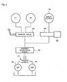
- Output sides of the mechanical oil pump 36 and the electric oil pump 40 are both connected to a switching check ball mechanism 41, as shown in Fig. 2.
- ATF supplied from one pump produces pressure to cause the check ball to stem the other supply hole to thereby switch the oil pressure supply sources.
- the output side of the switching check ball mechanism 41 is connected via a primary regulator valve 62 to a manual valve 64 and an input clutch control valve 66.
- the output side of the manual valve 64 is in turn connected to a forward clutch C1 and a backward clutch C1 within the automatic transmission 18.
- the manual valve 64 can be controlled from the passenger cabin via a shift lever.
- the output side of the input clutch control valve 66 is connected to the input clutch 16, the input clutch control valve 66 being operable through an input clutch control solenoid 68.
- the secondary battery 32 and the fuel cell 34 are connected to the motor-generator 14 though the power source switching switch 50 and the inverter 48 and to the auxiliary motor-generator 30 through the power source switching switch 49 and the inverter 46.
- the power source switching switches 49, 50 independently operate in response to an output from the controller 52, described below, so that the secondary battery 32 or the fuel cell 34 can selectively feed power to the motor-generator 14 and the auxiliary motor-generator 30.
- the secondary battery 32 has an SOC sensor 42 for detecting its state of charge, or SOC.
- the fuel cell 34 has a remaining amount sensor 44 for detecting an amount of fuel remaining therein.
- the automatic transmission 18 has control positions, including a D-position for automatic selection of the most appropriate step from among the respective transmission steps for forward progression, a 2-position and an L-position for selecting an appropriate step from limited transmission steps, an N-position for placing the gear transmission section 22 in a neutral position in which no driving force is transmitted, an R-position for selecting reverse, a P-position for mechanically locking the output side of the gear transmission section 22 so that the vehicle 10 is unable to move.
- This apparatus additionally comprises a manual transmission mode for allowing the driver to select a transmission step. In the manual transmission mode, the driver is able to shift the transmission gearing up or down in stages by operating a shift lever or switch
- a navigation section comprises a current location sensing section, a map information storage section, and a route guidance section, all not shown.
- the current location sensing section includes a Global Positioning System, or GPS, receiver which calculates a vehicle location through use of signals received from earth-orbiting satellites, a beacon receiver for receiving location information from a beacon installed along a road, a direction sensor, and a distance sensor.
- the GPS receiver and the beacon receiver are used for locating the vehicle in an area where receipt of information by these is possible, while inferential navigation is applied using direction and distance sensors in an area where the signals cannot be received.
- the map information storage section stores map data, road data, and destination data so that route search can be performed using the road and destination data.
- Road data may concern the width and length of each road, a coordinate position (latitude and longitude) at each point and the name and coordinate position of each crossing located between start and end points of each road, and so forth.
- a signal from the navigation section is supplied to a controller 52.
- a controller 52 is provided for controlling the respective sections of the vehicle 10.
- the controller 52 is configured in the form of a one-chip microprocessor with the CPU serving as a main elementand comprises a ROM for storing process programs, a RAM for temporarily storing data, a communication port, and input and output ports, all not shown.
- the controller 52 receives various signals indicating the state of the vehicle 10.
- the signals include a detection signal from a millimeter-wavelength radar installed at the leading end of the vehicle 10 for detecting proximity to a preceding vehicle, an output signal from an Antilock Brake System, or ABS, computer for controlling the ABS, a detection signal from a remaining amount sensor 44 for detecting an amount of fuel remaining in the fuel cell 34, a detection signal from an engine speed sensor for detecting rotation of the engine, a detection signal from an engine water temperature sensor, a detection signal from an ignition switch for controlling activation and suspension of operation of the vehicle 10, a detection signal from an SOC sensor 42 provided to the secondary battery 32, detection signals for detecting various operation states of a head light, a defogger, and an air conditioner, a detection signal from a vehicle speed sensor 56, a detection signal from an oil temperature sensor provided to a fluid pressure controller 24, a detection signal from a shift position sensor, a detection signal indicative of an operation state of the electric oil pump 40,
- the controller 52 in turn outputs various control signals to various actuators and other computers mounted to the vehicle 10.
- the signals may include an ignition signal to an ignition timing controller, an injection signal to a fuel injection system, a control signal to a control solenoid of the input clutch 16, control signals to the respective controllers for controlling the motor-generator 14 and the auxiliary motor-generator 30, a control signal to a decelerator, a control signal to a line pressure control solenoid of the automatic transmission 18, a control signal to an actuator of the above-mentioned ABS, a control signal to a sport mode indicator which indicates an operation state in association with the above-mentioned sport mode switch, control signals to the respective solenoids of the automatic transmission 18, a control signal to a lock-up control solenoid which controls lock-up of the automatic transmission 18, a control signal to the electric oil pump 40, control signals to the power source switching switches 49, 50, and so forth.
- the vehicle 10 applies driving source switching control, as described above. That is, as shown in Fig. 4, when an acceleration pedal angle (accelerator input ) and a vehicle speed are both small, such as when the vehicle 10 is idling or running at a low speed, the motor-generator 14 functions as a motor so that the vehicle 10 runs with a power from the motor-generator 14. When the acceleration pedal angle and vehicle speed are both large, such as when the vehicle 10 is running under a heavy load due to acceleration or hill-climbing, for example, the engine 12 is automatically activated so that the vehicle 10 runs with a power from the engine 12.
- the setting shown in Fig. 4 is associated with the automatic transmission 18 placed in D-position, and that other settings are applied for other positions.
- the motor-generator 14 functions as a generator to recharge electric power to the secondary battery 32 when the vehicle decelerates or brakes.
- the secondary battery 32 is charged either by electric power from the fuel cell 34 or by electric power from the motor-generator 14 which converts the power-upped engine output energy to electric power.
- the electric oil pump 40 is provided with activation and suspension control. Specifically, for running with power from the motor-generator 14 alone, the electric oil pump 40 is activated, when the vehicle 10 stops running or runs at a very slow speed, for continuation of oil pressure supply to a hydraulic mechanism including the automatic transmission 18. For running with power from the engine 12, on the other hand, operation of the electric oil pump 40 is suspended because the mechanical oil pump 36 is activated upon activation of the engine 12.
- an acceptable operation time for the electric oil pump 40 is set through the following control. Referring to Fig. 5, whether or not the vehicle 10 currently runs with power from the motor-generator 14 is determined (S102). This determination is performed because the mechanical oil pump 36 operates when the vehicle is stopped, while the engine 12 is rotating under a predetermined idling speed. But, the mechanical oil pump 36 does not operate when the vehicle 10 is stopped while the motor-generator 14 is used for running. When the motor-generator 14 then stops operating, the electric oil pump 40 is utilized. Therefore, supposing that the vehicle 10 is in the latter case, the control for the electric oil pump being described here may be necessary.
- the determination at S102 may be made based on detection signals from the engine speed sensor and the vehicle speed sensor 56. Alternatively, a control signal to the motor-generator 14 may be relied on. When the determination is negative, this process routine is terminated.
- a navigation is determined to be applicable when a running prediction concerning reactivation of the engine 12 by other factors can be made based on a running state (S104). This determination is made based on whether or not an effective running prediction described later can be made. When the determination is negative, a relatively short second standard value, for example, seven minutes is set as an acceptable operation time for the electric oil pump 40 (S106).
- a running prediction is made based on a running state (S108).
- This running prediction concerns a timing at which to automatically suspend the operation of the electric oil pump 40 through other control, including the following two situations.
- a first situation involves a case wherein the electric oil pump 40 is automatically suspended following automatic activation of the engine to be applied to handle heavily loaded driving such as hill climbing or acceleration. Specifically, when such a prediction is made, based on the present location of the vehicle relative to the destination and the current vehicle speed, that the vehicle will enter a highways or a vehicle-only-road in a few minutes and therefore undergo high-speed and heavily-loaded driving, the time left before that event is calculated.
- a second situation involves a case wherein the electric oil pump 40 is suspended following stop of driving the vehicle 10 due to termination of using the vehicle 10. Specifically, when such a prediction is made, based on the present location of the vehicle relative to the destination and the current vehicle speed, that the vehicle 10 will reach the destination in a few minutes and therefore running will stop, the time left before that event is calculated.
- a relatively long first standard value for example, nine minutes, is set as an acceptable operation time for the electric oil pump 40 (S110).
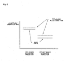
- an acceptable operation time to be set at S106 and S110 includes a base value and a constant prolonged acceptable time, as shown in Fig. 6.
- a prolonged acceptable time is a time period within which operation of the electric oil pump 40 is continued even after the lapse of a period of time corresponding to a base value in the case where a period of time left before the expected automatic suspension of the electric oil pump 40 is shorter than the prolonged acceptable time. This arrangement reduces frequency of brief activating of the engine 12, and thus achieves further reduction of fuel consumption.
- continuation of operation of the electric oil pump 40 is limited to a case where the period of time left before the expected automatic suspension is effected is shorter than a prolonged acceptable time, wear of the electric oil pump 40 can be suppressed.
- a timing for the brief activation of the engine 12 based on a catalyst temperature can be changed by changing a standard catalyst temperature value depending on a running prediction based on a running state.
- This running prediction concerns a timing at which an operating state of the engine 12 is varied based on other factors, including the following two situations.
- a first situation relates to automatic activation of the engine 12 to be applied to handle a heavily loaded driving such as acceleration or climbing a hill. Specifically, when such a prediction is made, based on the present location of the vehicle relative to the destination and the current vehicle speed, that the vehicle will enter a highway or a vehicle-only-road in a few minutes and therefore undergo high-speed-and heavily-loaded driving the time left before that event is calculated.
- a second situation relates to suspension of the engine 12 following stop of driving the vehicle 10 due to termination of using the vehicle 10. Specifically, when such a prediction is made, based on the present location of the vehicle relative to the destination and the current vehicle speed, that the vehicle 10 will reach the destination in a few minutes and therefore be stopped running, the time left before that event is calculated.
- the calculated period of time before automatic activation of the engine 12 or termination of driving the vehicle 10 is compared with a predetermined standard time.
- a smaller activation delay standard value T2 is set in the place of a normal standard value T1 as a standard value for brief activation of the engine 12 based on a catalyst temperature.
- the catalyst temperature varies as indicated by the solid line A in Fig. 7
- brief activation of the engine 12 based on a catalyst temperature is applied at t3 for an activation delay standard value T2, as opposed to at t1 for a normal standard value T1. That is, a timing for the brief activation is delayed.
- a period of time in which the electric oil pump 40 has been successively operating, or a successive operating time is compared with the acceptable operation times for the electric oil pump 40 (first and second standard values), which are previously set at S106 and S110 (S118).
- the successive operating time is within the acceptable operation time, a positive determination is made and driving with power from the motor-generator 14 is continued, so that supply of oil pressure by the electric oil pump 40 is continued.
- the duration of brief activation of the engine 12 at S124 may vary according to circumstances because a required period of time with the engine 12 remaining activated may differ depending on the purpose of the activation, such as charging the secondary battery 32, maintaining a catalyst temperature, reducing an operating time of the electric oil pump 40, and so forth.
- the electric oil pump 40 is allowed to operate only within a predetermined acceptable operation time. This can limit a successive operating time of the electric oil pump 40, and resultantly suppress wearing of the electric oil pump 40. As a result, the life of the electric oil pump 40 can be prolonged. Moreover, provision of a larger electric oil pump 40 can be avoided.
- the engine 12 is activated when the successive operating time of the electric oil pump 40 exceeds a predetermined acceptable operation time. Accordingly, the mechanical oil pump 36 is activated after suspension of the electric oil pump 40, so that supply of oil pressure is continued.
- an acceptable operation time for the electric oil pump 40 is set according to a running state, the electric oil pump 40 can continue to operate when the vehicle is in such a running state that prefers no pump switching. As a result, drivability can be improved.
- an acceptable operation time is set according to a running prediction. This makes it possible to delay brief activation of the engine 12 according to a running prediction. As a result, fuel consumption can be improved.
- the running prediction utilized in setting an acceptable operation time concerns a timing at which to automatically suspend the electric oil pump 40 through the above-described control in this embodiment (S106, 3110)
- the setting may be based on other types of running prediction.
- a running prediction concerning a successive operating time of the engine 12 after reactivation may base the setting of an acceptable operation time of the electric oil pump 40.
- a relatively long acceptable operation time may be set for the electric oil pump 40 upon prediction of a relatively long successive operating time of the engine 12 to follow after reactivation.
- a running prediction concerning a successive suspending time of the electric oil pump 40 may base the setting of an acceptable operation time of the electric oil pump 40.
- a relatively long acceptable operation time may be set for the electric oil pump 40 upon prediction of a relatively long successive suspending time of the electric oil pump 40 to follow.
- timing for brief activation of the engine 12 based on a catalyst temperature is changed based on a running prediction in the example illustrating this embodiment (S116)
- other structures may be provided instead, or additionally, such as a structure in which the timing is changed depending on a dropping or changing rate of the catalyst temperature.
- An example structure may determine a slow dropping rate, that is, a high ambient temperature, when an absolute value of the gradient of a changing catalyst temperature in the immediate past is equal to or smaller than a predetermined value, and delays a timing for reactivation of the engine 12. This structure relies on an assumption that the catalyst temperature can recover swiftly at a high ambient temperature. The determination may be made based on a detection signal from an outside temperature sensor desirably installed to the vehicle 10.
- a general standard value T1 may be used as a standard value for brief activation of the engine 12 based on a catalyst temperature in the case of the solid line A in Fig. 7, which represents falling of a catalyst temperature at a higher rate.
- an activation delay standard value T2 may be used in the case of the broken line B in Fig. 7, which represents falling of a catalyst temperature at a lower rate, as a higher ambient temperature is assumed in this case and therefore swift recovery of the catalyst temperature is expected.
- the timing for brief activation of the engine 12 based on a catalyst temperature is delayed to t4, as opposed to t2 for a general standard value T1.
- a timing for brief activation of the engine 12 based on a catalyst temperature can be delayed, so that fuel consumption can be improved.
- a vehicle 110 performs automatic reactivation and automatic suspension of an engine 112 according to a state of the vehicle 110 (hereinafter referred to as eco-run control). With this vehicle 110, a successive operating time of the electric oil pump 140 is changed based on an accumulated operation time of the electric oil pump 140.
- an engine 112 is connected to a starter 111 which can activate the engine 112, and further to an auxiliary motor-generator 130 via a power transmission mechanism 128, which can activate the connected engine 112 and also function as a generator.
- the power transmission mechanism 128 maybe a gear array or a flexible member, such as a belt or chain.
- the auxiliary motor-generator 130 may be a synchronous electric motor, and may be used in place of the starter 111 when reactivating the engine 112 while eco-run control, described later, is being applied.
- the auxiliary motor-generator 130 also regenerates power while the engine 112 is being braked. Further, the auxiliary motor-generator 130 functions as a motor while the engine 112 remains not operating, driving the accessories including an air conditioner compressor, a water pump, a power steering pump, all not shown, and so forth, in a situation wherein power transmission to the engine 112 through the power transmission mechanism 128 is disconnected.
- the auxiliary motor-generator 130 is connected to a secondary battery via a relay, not shown, and activated in response to a control output to the relay from the controller 152, as described below.
- the engine 112 is an internal combustion engine using gasoline as fuel.
- the engine 112 has a fuel injection system, not shown, for direct injection of fuel to a combustion chamber, not shown, and a throttle actuator for opening or closing a throttle valve installed to an inlet pipe of the engine 112. Through control of a period of time with the valve of the fuel injection system remaining open and of opening of the throttle valve, driving state is controlled.
- the drive shaft of the engine 112 is directly connected to a mechanical oil pump 136 via a torque converter 120.
- the automatic transmission 118 comprises a torque converter 120, a gear transmission section 122, and a fluid pressure controller 124 for controlling the gear transmission section 122.
- the automatic transmission 118 automatically selects a gear ratio according to a running state. A gear ratio may also be selected according to an operation state of a shift lever, not shown, installed in the interior of the vehicle room.
- an electric oil pump 140 is provided in addition to the above-described mechanical oil pump 136.
- the electric oil pump 140 is installed in the vicinity of the gear transmission section 122.
- a driving motor, not shown, of the electric oil pump 140 is connected to a secondary battery through a relay, not shown, and activated in response to a control output to the relay from a controller 152, described later.
- the electric oil pump 140 has a smaller capacity than that of the mechanical oil pump 136, and is designed to be adapted to lower pressure and a smaller fluid amount for reduction of size and power consumption.
- the electric oil pump 140 and the mechanical oil pump 136 are connected to an oil pressure control circuit which is provided inside of the gear transmission section 122 and controls operation of the gear transmission section 122.
- the oil pressure control circuit includes an oil pressure path 131, as shown in Fig. 9, through which oil pressure is transmitted to a forward clutch C1 which is brought into engagement for progression.
- an electric oil pump 140 and a mechanical oil pump 136 are connected to a primary regulator valve 135 in a manner such that they diverged therefrom via a switching check ball mechanism 141.
- ATF supplied from one pump creates a pressure which causes the check ball to stem the supply hole of the other pump, to thereby switch the supply sources.
- Oil pressure at the primary regulator valve 135 is adjusted by an AT line pressure control solenoid 137.
- the output side of the primary regulator valve 135 is connected to the forward clutch C1 through the manual valve 164 for transmitting the line pressure to the respective working sections depending on an operation position of a shift level installed in the driver's place, and further through an orifice 133.
- An adjustment accumulator 143 is connected to the oil pressure path such that it diverges therefrom through an orifice 142.
- the accumulator 143 shown in Fig. 9 has a piston 145 and a spring 147, and functions such that a predetermined oil pressure defined by the spring 147 is maintained for a predetermined period of time when oil is supplied to the forward clutch C1, whereby the forward clutch C1 is maintained in an engaged state.
- the controller 152 is configured in the form of a one-chip microprocessor with the CPU serving as a main element, comprising a ROM for storing process programs, a RAM for temporarily storing data, a communication port for communicating with a controller and so forth, and input and output ports, all not shown.
- the controller 152 has various sensors connected thereto. That is, an input side of the controller 152 is connected to an engine speed sensor and an engine water temperatures sensor, both mounted to the engine 112, an ignition switch provided in the interior of the vehicle room, a remaining amount sensor for detecting an amount of fuel remaining in a fuel cell, an SOC sensor provided to a secondary cell, accessories including a head light, a defogger, and an air conditioner, a vehicle speed sensor mounted to a driving wheel, an AT oil temperature sensor provided to an automatic transmission, a shift position sensor mounted to a base of a shift lever, an emergency brake position sensor mounted to an emergency brake lever, a brake pedal sensor mounted to a brake pedal, a catalyst temperature sensor incorporated into an exhaustion pipe, a throttle opening sensor provided to a throttle valve actuator, a crank angle sensor mounted to a crank shaft, a rotation sensor provided to a turbine, and an outside temperature sensor, an interior temperature sensor, and so forth, and receives detection values from these sensors.
- An output side of the controller 152 is connected to an ignition device, a fuel injection system, controllers for controlling operations of the starter 111 and the auxiliary motor-generator 130, an AT solenoid for controlling an oil pressure control circuit of the gear transmission section 122, an AT line pressure control solenoid 137, an ABS actuator, an working state automatic suspension control indicator and a not-working state automatic suspension control indicator, both installed in the interior of the vehicle room, a relay for a driving motor of the electric oil pump 40, an electronic throttle valve, and so forth, and outputs actuation signals to the various devices.
- the controller 152 applies eco-run control depending on the vehicle state.
- the engine 112 is automatically suspended when the following conditions are held, for the shift lever in N-position or P-position, "a vehicle speed zero (the vehicle is stopped)” AND “acceleration off (accelerator pedal not depressed), and, for the shift lever in D-position, “a vehicle speed zero” AND “acceleration off” AND “brake on (a brake pedal depressed).
- the condition may include "an idle switch off", "a predetermined or larger SOC value", "a predetermined or higher outside temperature”, “a predetermined or higher engine water temperature”, and so forth.
- Whether or not the vehicle speed is zero is determined based on a detection value of the vehicle speed sensor.
- a state of stepping the acceleration and brake pedals is determined based on various position signals detected by an accelerator pedal position sensor and a brake pedal sensor.
- the engine 112 is automatically activated when any the automatic suspension condition or conditions no longer apply.
- Automatic suspension of the engine 112 is applied by suspending fuel injection and suspending power feeding to the ignition plague, while reactivation of the engine 112 is applied by resuming these suspended operations and also driving the auxiliary motor-generator 130.
- the eco-run control is applied, for example, when a vehicle 112 running in a city area stops at a crossing, waiting for a signal to change, to improve fuel consumption and reduce emission.
- Fig. 11 shows a flowchart showing an example control routine to be executed by the controller 152. This routine is repetitively conducted for every predetermined period of time after an ignition key, not shown, is turned on.
- a counter value Y of a successive operating time counter is read out, and whether or not the read counter value is in excess of a predetermined standard value Tc is determined (5204).
- a counter value of an accumulated operation time counter is also read out, and whether or not the read counter value X is in excess of a predetermined standard value Tz is determined (S206). When neither determination is positive, the process proceeds to S208.
- a suspension request to the engine 112 and an activation request to the electric oil pump 140 are output, respectively (S208).
- the suspension request to the engine 112 is made by discontinuing fuel supply and halting ignition, and the activation request to the electric oil pump 140 is made through operation of a relay for a driving motor of the electric oil pump 140.
- earlier output of a signal to the electric oil pump 140 to prompt the electric oil pump 140 to activate prior to suspension of the engine 112 is preferred as supply of a working oil can be continued by the electric oil pump 140 to ensure oil pressure.
- the successive operating time counter is a software counter set in the controller 152 and tasked to detect an amount of time of each operation of the electric oil pump 140.
- a counter value of the accumulated operation time counter is incremented (S210).
- the accumulated operation time counter is a software counter similarly set in the controller 152 and tasked to count an accumulated operation time which counts an amount of time of each operation and reflects past operation and suspension of the electric oil pump 140.
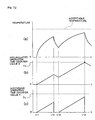
- the accumulated operation time is obtained by subtracting at a constant rate an amount of time having elapsed after suspension of operation of the electric oil pump 140 from each operation time of the electric oil pump 140 and, after activation of the electric oil pump 140, then by adding at a constant rate to the resultant operation time at the activation, an amount of time having elapsed from the activation, that is, an operation time. That is, this calculation of an accumulated operation time corresponds to application of correction based on an operation history to an operating time for every operation. As a result, the accumulated operation time changes substantially according to the temperature of a driving motor which drives the electric oil pump 140, as shown in Fig. 12.
- Processes at S204 to S212 are repetitively applied until the controller 152 requests the engine 112 to activate operation (S214). Therefore, counter values of the successive operating time counter and the accumulated operation time counter continue increasing at a constant rate until the activation request is made.
- Tz, Tc are determined based on an acceptable temperature which is determined in consideration of durability of a brush of the driving motor of the electric oil pump 140 and a welded portion of the driving circuit which feeds power to the driving motor.
- the counter value of the accumulated operation time counter is made to begin decreasing (S220).
- the decrease is achieved through subtraction at a constant rate relative to the counter value of the accumulated operation time counter, and continued until the counter value becomes zero or next increment of the counter value of the accumulated operation time counter (S212) is resumed.
- the temperature of the driving motor of the electric oil pump 140 for example, the temperature of the brush
- Fig. 9 (a) the temperature of the driving motor increases according to a predetermined saturation curve.
- operation of the electric oil pump 140 is suspended at time t12 in response to a suspension request to the electric oil pump 140, which accompanies an activation request to the engine 112 resulting, for example, from driver operation of the accelerator pedal, the temperature of the driving motor begins to fall.
- the temperature of the driving motor accordingly begins to increase.
- the counter value X (Fig. 9 (b)) of the accumulated operation time counter reaches a standard value Tz (t14)
- the engine 112 is activated, and the electric oil pump 140 is suspended (S216). Therefore, the temperature of the driving motor begins dropping again without reaching an acceptable temperature, that is, an acceptable temperature determined in consideration of the durability of the brush of the driving motor and of a welded portion of the driving circuit which feeds power to the driving motor.
- a successive operating time of the electric oil pump 140 is corrected based on an operation history through calculation and utilization of an accumulated operation time. This achieves appropriate driving in consideration of an operation history of the electric oil pump 140.
- the elapsed from completion of the last operation of the electric oil pump (t12 in Fig. 9 (c)) is utilized and the counter value of the accumulated operating time counter is subtracted at a constant rate based on the elapsed time.
- information concerning the last operation of the electric oil pump 140 in particular, the temperature of the driving motor at the time of completion of the last operation, is obtained based on an operation time and an amount of correction to be applied to the successive operating time is corrected based on the last operating time.
- another structure may be usable, such as one in which a counter value is corrected using a predetermined function to attain more precise approximation of the driving motor temperature.
- a counter value is corrected using a predetermined function to attain more precise approximation of the driving motor temperature.
- correction may be applied to the counter values of the respective counters using a predetermined function based on these detection values.
- the correction may be applied to the counter values using a predetermined map or table.
- a structure in which all operations having been executed throughout the life of the driving motor of the electric oil pump 140 up to the present are considered may be employed.
- a lower value is set for a standard value which defines an upper limit of a successive operation time of the electric oil pup 140, during a predetermined initial adaptation operation period during which the driving motor may need running-in, or a certain period of time near the end of the life of the driving motor during which an acceptable temperature may possibly drop due to obsolescence.
- Such structures are also included in the scope of the present invention.
- another structure may also be applicable to produce the same advantage.
- a structure in which an acceptable operation time is changed based on an accumulated operation time may be employed.
- a lower standard value Tc for the successive operating time counter may be set for a higher counter value of the accumulated operation time counter.
- the mechanical oil pumps 36, 136 which are driven by a mechanical output from a driving source including the engines 12, 112 or the motor-generator 14 are used in the above embodiments
- the mechanical oil pumps 36, 136 may be substituted by, for example, an electric oil pump, serving as a first pump, which is driven by electric power from a fuel cell, and the first electric oil pump may be used while being desirably switched with the second electric oil pump 140.
- the second pump in the present invention is not limited to a pump which is driven by power of a driving motor but any electric power-driven pump having a different structure may be employed.
- an oil pump which is driven by an output shaft of the auxiliary motor-generator 130 may be employed.
- the present invention may be applied to a vehicle in which two pumps are switched to supply oil pressure to a hydraulic mechanism in a system other than a power transmission system, for example, an ABS, a Vehicle Stability Control System, or VSC, a power steering system, and so forth.
- a power transmission system for example, an ABS, a Vehicle Stability Control System, or VSC, a power steering system, and so forth.
- the present invention is incorporated into a hybrid vehicle which switches power from the engine 12 and the motor-generator 14 (the first embodiment) and a vehicle which has an engine 112 alone and utilizes automatic suspension and automatic activation of the engine 112 (the second embodiment) are referred to in the above description of the present invention
- application of the present invention is not limited to such vehicles and the present invention can be applied to other vehicles.
- a vehicle which operates using only a motor-generator is also included in the scope of the present invention.
- the present invention can be preferably utilized as an electric oil pump control device in a vehicle which effects activation and suspension of operation of a driving source such as an engine and a motor while the vehicle is running.
Landscapes
- Engineering & Computer Science (AREA)
- Mechanical Engineering (AREA)
- General Engineering & Computer Science (AREA)
- Chemical & Material Sciences (AREA)
- Combustion & Propulsion (AREA)
- Transportation (AREA)
- Control Of Vehicle Engines Or Engines For Specific Uses (AREA)
- Control Of Positive-Displacement Pumps (AREA)
Abstract
Description
Claims (7)
- An electric oil pump controller, comprising:whereina driving source;a driving source controller for activating and suspending operation of the driving source under a predetermined condition;a first pump;a second pump to be driven by electric energy;a pump controller for operating the second pump when the first pump is not operating; anda hydraulic mechanism to be driven by oil pressure supplied from the first pump and the second pump,
the pump controller causes the second pump to operate until a successive operating time of the second pump exceeds a predetermined acceptable operation time. - The electric oil pump controller according to claim 1, wherein the first pump is driven by a mechanical output from the driving source.
- The electric oil pump controller according to claim 1, wherein the driving source controller activates the driving source when the successive operating time of the second pump exceeds the acceptable operation time.
- The electric oil pump controller according to claim 1, wherein the acceptable operation time is set according to a measured value of physical property indicative of a state of the vehicle.
- The electric oil pump controller according to claim 1, further comprising:whereina prediction device for making a running prediction according to a state of the vehicle,
the acceptable operation time is set according to the running prediction. - The electric oil pump controller according to claim 1, further comprising:a correction device for correcting at least one of the successive operating time and the acceptable operation time based on operation history of the second pump.
- The electric oil pump controller according to claim 6, wherein the operation history is a time having elapsed from last operation of the second pump.
Applications Claiming Priority (5)
| Application Number | Priority Date | Filing Date | Title |
|---|---|---|---|
| JP2000268081 | 2000-09-05 | ||
| JP2000268081 | 2000-09-05 | ||
| JP2001181171A JP3867521B2 (en) | 2000-09-05 | 2001-06-15 | Electric oil pump control device |
| JP2001181171 | 2001-06-15 | ||
| PCT/JP2001/007635 WO2002020991A1 (en) | 2000-09-05 | 2001-09-04 | Electric oil pump controller |
Publications (3)
| Publication Number | Publication Date |
|---|---|
| EP1316727A1 true EP1316727A1 (en) | 2003-06-04 |
| EP1316727A4 EP1316727A4 (en) | 2008-07-09 |
| EP1316727B1 EP1316727B1 (en) | 2011-04-20 |
Family
ID=26599236
Family Applications (1)
| Application Number | Title | Priority Date | Filing Date |
|---|---|---|---|
| EP01961339A Expired - Lifetime EP1316727B1 (en) | 2000-09-05 | 2001-09-04 | Electric oil pump controller |
Country Status (7)
| Country | Link |
|---|---|
| US (1) | US6709362B2 (en) |
| EP (1) | EP1316727B1 (en) |
| JP (1) | JP3867521B2 (en) |
| KR (1) | KR100488642B1 (en) |
| CN (1) | CN1267643C (en) |
| DE (1) | DE60144480D1 (en) |
| WO (1) | WO2002020991A1 (en) |
Cited By (9)
| Publication number | Priority date | Publication date | Assignee | Title |
|---|---|---|---|---|
| DE102005002210B4 (en) * | 2004-01-22 | 2009-11-05 | Toyota Jidosha Kabushiki Kaisha, Toyota-shi | Control system for hybrid vehicles |
| WO2010127740A1 (en) * | 2009-05-05 | 2010-11-11 | Daimler Ag | Drive train device |
| CN101992772A (en) * | 2009-08-19 | 2011-03-30 | 通用汽车环球科技运作公司 | Method of operating oil supply using estimated future oil pressure |
| EP2580081A1 (en) * | 2010-05-28 | 2013-04-17 | Bayerische Motoren Werke Aktiengesellschaft | Hybrid module |
| WO2013104063A1 (en) | 2012-01-11 | 2013-07-18 | Developpement Effenco Inc. | Fuel saving system that facilitates vehicle re-starts with the engine off |
| FR2996614A1 (en) * | 2012-10-10 | 2014-04-11 | Peugeot Citroen Automobiles Sa | System for decreasing provision time of pump unit of gearbox of hybrid vehicle, has control units for identifying data to anticipate transmission of signal for increasing pressure of pump unit to position change to status to any actuation |
| DE102005058956B4 (en) * | 2004-12-10 | 2016-01-07 | Aisin Aw Co., Ltd. | A power output apparatus, a power output apparatus control system, and a power output apparatus control method |
| DE102009041236B4 (en) | 2009-09-11 | 2018-08-16 | Daimler Ag | A power train assembly |
| US10703356B2 (en) | 2016-02-16 | 2020-07-07 | Développement Effenco Inc. | Expanded functionality stop-start fuel saving system for vocational vehicles |
Families Citing this family (71)
| Publication number | Priority date | Publication date | Assignee | Title |
|---|---|---|---|---|
| FR2768324B1 (en) * | 1997-09-12 | 1999-12-10 | Jacques Seguin | SURGICAL INSTRUMENT FOR PERCUTANEOUSLY FIXING TWO AREAS OF SOFT TISSUE, NORMALLY MUTUALLY REMOTE, TO ONE ANOTHER |
| US20040044350A1 (en) * | 1999-04-09 | 2004-03-04 | Evalve, Inc. | Steerable access sheath and methods of use |
| JP3998991B2 (en) * | 2002-02-05 | 2007-10-31 | 本田技研工業株式会社 | Vehicle equipped with electric motor |
| JP3574121B2 (en) * | 2002-08-07 | 2004-10-06 | 本田技研工業株式会社 | Engine stop / start control device for hybrid vehicle |
| US7147072B2 (en) * | 2003-04-24 | 2006-12-12 | Delphi Technologies, Inc. | Method and apparatus for providing hybrid power in vehicle |
| JP4130155B2 (en) * | 2003-05-29 | 2008-08-06 | トヨタ自動車株式会社 | Vehicle drive device |
| JP3963868B2 (en) * | 2003-06-23 | 2007-08-22 | トヨタ自動車株式会社 | Control device for hybrid drive |
| JP3783715B2 (en) * | 2004-01-22 | 2006-06-07 | トヨタ自動車株式会社 | Control device for hybrid vehicle |
| JP3783714B2 (en) * | 2004-01-22 | 2006-06-07 | トヨタ自動車株式会社 | Control device for hybrid vehicle |
| DE112005000728T5 (en) | 2004-03-31 | 2007-03-22 | Kobelco Cranes Co., Ltd. | Crane and method of assembling the crane |
| JP3921220B2 (en) * | 2004-12-02 | 2007-05-30 | 本田技研工業株式会社 | Hydraulic supply device |
| FR2882700B1 (en) * | 2005-03-01 | 2008-10-31 | Peugeot Citroen Automobiles Sa | METHOD FOR TRANSMITTING POWER BETWEEN A HEAT ENGINE AND WHEELS OF A MOTOR VEHICLE AND ASSOCIATED DEVICE |
| DE102005024359B4 (en) * | 2005-05-27 | 2015-05-07 | Bayerische Motoren Werke Aktiengesellschaft | Hybrid drive device for a motor vehicle |
| DE102005046729B4 (en) * | 2005-09-29 | 2012-01-05 | Airbus Operations Gmbh | Energy supply system for the supply of aircraft systems |
| JP4007387B2 (en) * | 2006-01-24 | 2007-11-14 | トヨタ自動車株式会社 | Vehicle control device |
| US7546821B2 (en) * | 2006-03-02 | 2009-06-16 | Ford Global Technologies, Llc | Hydraulic actuation system for improved engine start |
| US7748353B2 (en) * | 2006-03-02 | 2010-07-06 | Ford Global Technologies, Llc | Hydraulic actuation system for improved engine control |
| US7465250B2 (en) * | 2006-03-10 | 2008-12-16 | Gm Global Technology Operations, Inc. | On-board hybrid transmission auxiliary-pump priming control system |
| JP4807123B2 (en) * | 2006-03-27 | 2011-11-02 | トヨタ自動車株式会社 | Transmission control device |
| US7543695B2 (en) * | 2006-07-21 | 2009-06-09 | Gm Global Technology Operations, Inc. | Hydraulic system for an electro-mechanical transmission and method of providing fluid to transmission components |
| US7568990B2 (en) * | 2006-08-04 | 2009-08-04 | Gm Global Technology Operations, Inc. | Method and apparatus to control operation of a hydraulic control circuit for an electro-mechanical transmission |
| KR101172090B1 (en) | 2006-08-18 | 2012-08-10 | 현대자동차주식회사 | Hybrid Powertrain Structure |
| JP4730316B2 (en) * | 2007-01-31 | 2011-07-20 | トヨタ自動車株式会社 | Cooling device for internal combustion engine |
| JP4475286B2 (en) * | 2007-04-02 | 2010-06-09 | トヨタ自動車株式会社 | Vehicle oil pump control device |
| JP4412346B2 (en) | 2007-04-20 | 2010-02-10 | トヨタ自動車株式会社 | Drive control apparatus for hybrid vehicle |
| US8459392B2 (en) * | 2007-06-22 | 2013-06-11 | Bombardier Recreational Products Inc. | Snowmobile having electronically controlled lubrication |
| JP5252171B2 (en) * | 2007-09-19 | 2013-07-31 | アイシン・エィ・ダブリュ株式会社 | Vehicle control device |
| KR100946524B1 (en) * | 2007-11-05 | 2010-03-11 | 현대자동차주식회사 | Electric oil pump drive control method of hybrid vehicle |
| US7972239B2 (en) * | 2008-02-12 | 2011-07-05 | Caterpillar Inc. | Dual pump design for hybrid electric automatic transmission |
| JP5309624B2 (en) * | 2008-03-11 | 2013-10-09 | 日産自動車株式会社 | Control device for hybrid vehicle |
| US8187147B2 (en) * | 2008-03-27 | 2012-05-29 | GM Global Technology Operations LLC | Hydraulic control system for multi-mode hybrid transmission and method of regulating the same |
| DE102009014732B4 (en) * | 2008-03-31 | 2019-11-28 | GM Global Technology Operations LLC (n. d. Ges. d. Staates Delaware) | Hydraulic control system for multi-mode hybrid transmission and method of controlling the same |
| US20100106350A1 (en) * | 2008-10-28 | 2010-04-29 | Glacier Bay, Inc. | Real-time efficiency monitoring for marine vessel |
| JP5266111B2 (en) * | 2009-03-19 | 2013-08-21 | 株式会社豊田中央研究所 | Hydraulic transmission device for automatic transmission |
| US8346421B2 (en) * | 2009-03-24 | 2013-01-01 | Ford Global Technologies, Llc | Method and system for initiating starting of an engine in a hybrid electric vehicle |
| US8062171B2 (en) * | 2009-05-01 | 2011-11-22 | Ford Global Technologies, Llc | Transmission engagement control during an engine restart of a hybrid electric vehicle |
| JP2010281432A (en) * | 2009-06-08 | 2010-12-16 | Toyota Central R&D Labs Inc | Hydraulic transmission device for automatic transmission |
| JP4743317B2 (en) * | 2009-09-14 | 2011-08-10 | トヨタ自動車株式会社 | Hybrid vehicle drive control device and hybrid vehicle equipped with the same |
| CN102022303B (en) * | 2009-09-15 | 2013-05-08 | 上海华普汽车有限公司 | Dual-driving oil pump and control system thereof |
| JP5191971B2 (en) * | 2009-10-06 | 2013-05-08 | ジヤトコ株式会社 | Vehicle oil pump control device |
| WO2011070664A1 (en) * | 2009-12-10 | 2011-06-16 | トヨタ自動車 株式会社 | Control device for internal combustion engine |
| DE102009054754B4 (en) * | 2009-12-16 | 2019-02-07 | Zf Friedrichshafen Ag | Method for operating an electric auxiliary pump, device for carrying out such a method, and hydraulic system with such a device. |
| US7935025B1 (en) * | 2010-02-25 | 2011-05-03 | Ford Global Technologies, Llc | Methods and systems for assisted direct start control |
| US8585548B2 (en) * | 2010-10-08 | 2013-11-19 | GM Global Technology Operations LLC | System and method for controlling an automatic engine stop-start |
| US8702562B2 (en) * | 2010-10-11 | 2014-04-22 | Gm Global Technology Operations | System and method for controlling an automatic engine stop-start based on transmission conditions |
| CN102691650B (en) * | 2011-03-22 | 2015-07-01 | 日立汽车系统株式会社 | Apparatus and method for controlling electric oil pump |
| JP5437336B2 (en) * | 2011-09-22 | 2014-03-12 | 日立オートモティブシステムズ株式会社 | Electric oil pump control device |
| JP2013193511A (en) * | 2012-03-16 | 2013-09-30 | Toyota Motor Corp | Vehicle control system |
| JP5912705B2 (en) | 2012-03-16 | 2016-04-27 | トヨタ自動車株式会社 | Vehicle control system |
| DE102012206041A1 (en) * | 2012-04-13 | 2013-10-17 | Zf Friedrichshafen Ag | Apparatus and method for driving an auxiliary pump of a transmission |
| JP6167476B2 (en) * | 2012-06-04 | 2017-07-26 | スズキ株式会社 | Oil circulation system for electric motors mounted on hybrid vehicles |
| US9650925B2 (en) * | 2012-07-25 | 2017-05-16 | Cummins Intellectual Property, Inc. | System and method of augmenting low oil pressure in an internal combustion engine |
| DE102013218703B4 (en) * | 2012-09-24 | 2022-03-31 | GM Global Technology Operations LLC (n. d. Ges. d. Staates Delaware) | METHOD OF CONTROLLING AN AUTOMATIC START/STOP |
| US9090241B2 (en) * | 2012-09-24 | 2015-07-28 | Gm Global Technology Operations, Llc | System and method for controlling an automatic stop-start |
| JP5464247B1 (en) * | 2012-09-26 | 2014-04-09 | ダイキン工業株式会社 | Control device |
| AU2013338541B2 (en) | 2012-10-31 | 2016-04-28 | Allison Transmission, Inc. | Method of controlling a hydraulic pressurization system of a transmission |
| JP5741563B2 (en) * | 2012-12-06 | 2015-07-01 | トヨタ自動車株式会社 | Power transmission device |
| CN104343670B (en) * | 2013-07-31 | 2016-11-09 | 上海汽车集团股份有限公司 | A drive control method for an oil pump motor and a hydraulic system |
| US9352738B2 (en) | 2013-07-31 | 2016-05-31 | Allison Transmission, Inc. | Dual clutch powertrain architecture |
| US9477236B2 (en) | 2014-06-23 | 2016-10-25 | Ford Global Technologies, Llc | Vehicle system and method for providing anticipatory line pressure for transmission engagements |
| BE1022719B1 (en) * | 2015-02-13 | 2016-08-23 | Atlas Copco Airpower Naamloze Vennootschap | Compressor device |
| KR101755804B1 (en) | 2015-07-07 | 2017-07-07 | 현대자동차주식회사 | Recovered power transfer apparatus of waste heat recovery system |
| US20170107804A1 (en) * | 2015-10-14 | 2017-04-20 | David A. Krug | Hybrid prime motivator for rod pump hydraulic surface unit |
| JP6756606B2 (en) * | 2016-12-20 | 2020-09-16 | トヨタ自動車株式会社 | Hybrid vehicle |
| SE541356C2 (en) | 2017-04-21 | 2019-08-13 | Scania Cv Ab | Method and control arrangement for controlling vehicle free-wheel with engine off and power steering |
| KR101921879B1 (en) * | 2017-06-07 | 2018-11-27 | 현대 파워텍 주식회사 | Apparatus and method for controlling oil pump of automatic transmission |
| JP7261579B2 (en) | 2018-12-20 | 2023-04-20 | 株式会社日立産機システム | Fluid mechanical system and its control method |
| US11420609B2 (en) | 2020-12-14 | 2022-08-23 | Allison Transmission, Inc. | System and method for controlling engine stop-start events |
| JP7532299B2 (en) * | 2021-03-30 | 2024-08-13 | 株式会社神戸製鋼所 | Compressor Unit |
| KR102370626B1 (en) * | 2021-12-20 | 2022-03-03 | 이창수 | Dual pump smart control system |
| CN119467118B (en) * | 2024-11-11 | 2026-03-13 | 中国第一汽车股份有限公司 | Vehicle oil pump control methods, devices and electronic equipment |
Family Cites Families (25)
| Publication number | Priority date | Publication date | Assignee | Title |
|---|---|---|---|---|
| US3923423A (en) * | 1973-12-12 | 1975-12-02 | John A Lauck | Emergency control valve |
| JPS5276702A (en) * | 1975-12-22 | 1977-06-28 | Hitachi Ltd | Selective control system |
| US4531485A (en) * | 1984-03-01 | 1985-07-30 | Murther Howard D | Over ride oil pump |
| JPH04109028A (en) | 1990-08-27 | 1992-04-10 | Nippondenso Co Ltd | Cooling device for internal combustion engine |
| JPH04140560A (en) * | 1990-10-02 | 1992-05-14 | Kawasaki Heavy Ind Ltd | Multiple stage automatic transmission for vehicle |
| JPH086110A (en) | 1994-06-23 | 1996-01-12 | Nikon Corp | Focal plane shutter |
| JP3322072B2 (en) * | 1994-08-12 | 2002-09-09 | トヨタ自動車株式会社 | Power transmission lubrication system |
| JP3861340B2 (en) * | 1996-09-11 | 2006-12-20 | アイシン・エィ・ダブリュ株式会社 | Electric oil pump control device for vehicle power transmission device |
| JP3629890B2 (en) * | 1997-05-22 | 2005-03-16 | 日産自動車株式会社 | Hybrid system vehicle starter |
| JP3536627B2 (en) * | 1997-11-18 | 2004-06-14 | トヨタ自動車株式会社 | Vehicle drive unit |
| US6048288A (en) | 1997-11-18 | 2000-04-11 | Toyota Jidosha Kabushiki Kaisha | Power train system for a vehicle and method for operating same |
| JP2000046165A (en) | 1998-07-30 | 2000-02-18 | Toyota Motor Corp | Control device for vehicle drive unit |
| JP3835007B2 (en) * | 1998-07-30 | 2006-10-18 | トヨタ自動車株式会社 | Working fluid supply device for automatic transmission |
| JP4055297B2 (en) * | 1998-12-11 | 2008-03-05 | トヨタ自動車株式会社 | VEHICLE CONTROL DEVICE WITH ELECTRIC OIL PUMP FOR TRANSMISSION DEVICE |
| JP3840824B2 (en) | 1999-01-07 | 2006-11-01 | トヨタ自動車株式会社 | Vehicle control device |
| JP3852233B2 (en) | 1999-02-08 | 2006-11-29 | トヨタ自動車株式会社 | Power transmission device |
| JP4075189B2 (en) | 1999-02-08 | 2008-04-16 | トヨタ自動車株式会社 | Power output device |
| US6321697B1 (en) * | 1999-06-07 | 2001-11-27 | Mitsubishi Heavy Industries, Ltd. | Cooling apparatus for vehicular engine |
| JP2001193661A (en) * | 1999-06-08 | 2001-07-17 | Denso Corp | Hydraulic oil supply system and control method thereof |
| JP3750428B2 (en) * | 1999-07-26 | 2006-03-01 | 日産自動車株式会社 | vehicle |
| JP3827926B2 (en) * | 1999-07-29 | 2006-09-27 | 本田技研工業株式会社 | Hydraulic circuit and hydraulic control device for automatic transmission of automatic engine stop vehicle |
| US6253739B1 (en) * | 1999-12-17 | 2001-07-03 | Daimlerchrysler Corporation | Dual function fuel supply module |
| JP4066616B2 (en) * | 2000-08-02 | 2008-03-26 | トヨタ自動車株式会社 | Automatic start control device and power transmission state detection device for internal combustion engine |
| JP3898879B2 (en) * | 2000-08-25 | 2007-03-28 | ジヤトコ株式会社 | Control device for automatic transmission |
| US6556910B2 (en) * | 2001-08-31 | 2003-04-29 | Aisin Aw Co., Ltd. | Control apparatus and method for vehicle having an idle stop function |
-
2001
- 2001-06-15 JP JP2001181171A patent/JP3867521B2/en not_active Expired - Fee Related
- 2001-09-04 KR KR10-2003-7002653A patent/KR100488642B1/en not_active Expired - Fee Related
- 2001-09-04 EP EP01961339A patent/EP1316727B1/en not_active Expired - Lifetime
- 2001-09-04 CN CNB018151841A patent/CN1267643C/en not_active Expired - Fee Related
- 2001-09-04 DE DE60144480T patent/DE60144480D1/en not_active Expired - Lifetime
- 2001-09-04 WO PCT/JP2001/007635 patent/WO2002020991A1/en not_active Ceased
-
2003
- 2003-02-27 US US10/373,771 patent/US6709362B2/en not_active Expired - Fee Related
Cited By (12)
| Publication number | Priority date | Publication date | Assignee | Title |
|---|---|---|---|---|
| DE102005002210B4 (en) * | 2004-01-22 | 2009-11-05 | Toyota Jidosha Kabushiki Kaisha, Toyota-shi | Control system for hybrid vehicles |
| DE102005058956B4 (en) * | 2004-12-10 | 2016-01-07 | Aisin Aw Co., Ltd. | A power output apparatus, a power output apparatus control system, and a power output apparatus control method |
| WO2010127740A1 (en) * | 2009-05-05 | 2010-11-11 | Daimler Ag | Drive train device |
| US8955316B2 (en) | 2009-05-05 | 2015-02-17 | Daimler Ag | Drive train device |
| CN101992772A (en) * | 2009-08-19 | 2011-03-30 | 通用汽车环球科技运作公司 | Method of operating oil supply using estimated future oil pressure |
| DE102009041236B4 (en) | 2009-09-11 | 2018-08-16 | Daimler Ag | A power train assembly |
| EP2580081A1 (en) * | 2010-05-28 | 2013-04-17 | Bayerische Motoren Werke Aktiengesellschaft | Hybrid module |
| WO2013104063A1 (en) | 2012-01-11 | 2013-07-18 | Developpement Effenco Inc. | Fuel saving system that facilitates vehicle re-starts with the engine off |
| EP2804777A4 (en) * | 2012-01-11 | 2016-06-08 | Dev Effenco Inc | FUEL SAVING SYSTEM THAT ENABLES THE RESTART OF THE VEHICLE WHEN THE ENGINE IS STOPPED |
| EP4375152A3 (en) * | 2012-01-11 | 2024-07-31 | 14156048 Canada Inc. | Fuel saving system that facilitates vehicle re-starts with the engine off |
| FR2996614A1 (en) * | 2012-10-10 | 2014-04-11 | Peugeot Citroen Automobiles Sa | System for decreasing provision time of pump unit of gearbox of hybrid vehicle, has control units for identifying data to anticipate transmission of signal for increasing pressure of pump unit to position change to status to any actuation |
| US10703356B2 (en) | 2016-02-16 | 2020-07-07 | Développement Effenco Inc. | Expanded functionality stop-start fuel saving system for vocational vehicles |
Also Published As
| Publication number | Publication date |
|---|---|
| CN1452697A (en) | 2003-10-29 |
| KR100488642B1 (en) | 2005-05-11 |
| JP2002155865A (en) | 2002-05-31 |
| EP1316727A4 (en) | 2008-07-09 |
| EP1316727B1 (en) | 2011-04-20 |
| US6709362B2 (en) | 2004-03-23 |
| DE60144480D1 (en) | 2011-06-01 |
| JP3867521B2 (en) | 2007-01-10 |
| KR20030024907A (en) | 2003-03-26 |
| CN1267643C (en) | 2006-08-02 |
| WO2002020991A1 (en) | 2002-03-14 |
| US20030148850A1 (en) | 2003-08-07 |
Similar Documents
| Publication | Publication Date | Title |
|---|---|---|
| EP1316727B1 (en) | Electric oil pump controller | |
| US6346064B1 (en) | Driving force control unit for vehicles | |
| EP2928745B1 (en) | Hybrid electric vehicle control system and method | |
| US6283086B1 (en) | Engine control apparatus | |
| US6533081B2 (en) | Brake fluid pressure retaining apparatus | |
| US6401012B1 (en) | Vehicle control apparatus | |
| US6370466B1 (en) | Braking force retaining unit | |
| US6338398B1 (en) | Vehicle with braking force retaining unit | |
| US6388407B1 (en) | Apparatus for controlling a driving motor | |
| JP4207376B2 (en) | Vehicle hydraulic control device | |
| EP1616763B1 (en) | Vehicle with driving motor stopping unit | |
| KR20120117928A (en) | Hydraulic control device for automatic transmission | |
| US20150167796A1 (en) | Structure of power transmission apparatus | |
| US6336689B1 (en) | Brake fluid pressure retaining unit | |
| US6358182B1 (en) | Driving force control unit for vehicles | |
| JP2014019256A (en) | Road surface gradient estimation device of trailer vehicle | |
| US6328672B1 (en) | Driving force control unit for vehicle | |
| CN109969185B (en) | Method for operating a drive train of a motor vehicle | |
| JP4258522B2 (en) | Electric oil pump control device | |
| US10556591B2 (en) | Vehicle control device | |
| EP1065115B1 (en) | Driving force control unit for vehicles | |
| JP3488931B2 (en) | Control method and control device for internal combustion engine for vehicle | |
| JPH0790722B2 (en) | Constant speed traveling device | |
| JP2001001795A (en) | Control device for internal combustion engine | |
| JP2006142942A (en) | Brake system |
Legal Events
| Date | Code | Title | Description |
|---|---|---|---|
| PUAI | Public reference made under article 153(3) epc to a published international application that has entered the european phase |
Free format text: ORIGINAL CODE: 0009012 |
|
| 17P | Request for examination filed |
Effective date: 20030303 |
|
| AK | Designated contracting states |
Designated state(s): AT BE CH CY DE DK ES FI FR GB GR IE IT LI LU MC NL PT SE TR |
|
| AX | Request for extension of the european patent |
Extension state: AL LT LV MK RO SI |
|
| RBV | Designated contracting states (corrected) |
Designated state(s): AT BE CH DE FR GB LI |
|
| A4 | Supplementary search report drawn up and despatched |
Effective date: 20080606 |
|
| 17Q | First examination report despatched |
Effective date: 20081014 |
|
| GRAP | Despatch of communication of intention to grant a patent |
Free format text: ORIGINAL CODE: EPIDOSNIGR1 |
|
| RBV | Designated contracting states (corrected) |
Designated state(s): DE FR GB |
|
| GRAS | Grant fee paid |
Free format text: ORIGINAL CODE: EPIDOSNIGR3 |
|
| GRAA | (expected) grant |
Free format text: ORIGINAL CODE: 0009210 |
|
| AK | Designated contracting states |
Kind code of ref document: B1 Designated state(s): DE FR GB |
|
| REG | Reference to a national code |
Ref country code: GB Ref legal event code: FG4D |
|
| REF | Corresponds to: |
Ref document number: 60144480 Country of ref document: DE Date of ref document: 20110601 Kind code of ref document: P |
|
| REG | Reference to a national code |
Ref country code: DE Ref legal event code: R096 Ref document number: 60144480 Country of ref document: DE Effective date: 20110601 |
|
| PLBE | No opposition filed within time limit |
Free format text: ORIGINAL CODE: 0009261 |
|
| STAA | Information on the status of an ep patent application or granted ep patent |
Free format text: STATUS: NO OPPOSITION FILED WITHIN TIME LIMIT |
|
| 26N | No opposition filed |
Effective date: 20120123 |
|
| REG | Reference to a national code |
Ref country code: DE Ref legal event code: R097 Ref document number: 60144480 Country of ref document: DE Effective date: 20120123 |
|
| PGFP | Annual fee paid to national office [announced via postgrant information from national office to epo] |
Ref country code: GB Payment date: 20120829 Year of fee payment: 12 |
|
| PGFP | Annual fee paid to national office [announced via postgrant information from national office to epo] |
Ref country code: DE Payment date: 20120829 Year of fee payment: 12 Ref country code: FR Payment date: 20120926 Year of fee payment: 12 |
|
| REG | Reference to a national code |
Ref country code: GB Ref legal event code: 746 Effective date: 20130624 |
|
| REG | Reference to a national code |
Ref country code: DE Ref legal event code: R084 Ref document number: 60144480 Country of ref document: DE Effective date: 20130614 |
|
| GBPC | Gb: european patent ceased through non-payment of renewal fee |
Effective date: 20130904 |
|
| REG | Reference to a national code |
Ref country code: DE Ref legal event code: R119 Ref document number: 60144480 Country of ref document: DE Effective date: 20140401 |
|
| REG | Reference to a national code |
Ref country code: FR Ref legal event code: ST Effective date: 20140530 |
|
| PG25 | Lapsed in a contracting state [announced via postgrant information from national office to epo] |
Ref country code: GB Free format text: LAPSE BECAUSE OF NON-PAYMENT OF DUE FEES Effective date: 20130904 |
|
| PG25 | Lapsed in a contracting state [announced via postgrant information from national office to epo] |
Ref country code: FR Free format text: LAPSE BECAUSE OF NON-PAYMENT OF DUE FEES Effective date: 20130930 Ref country code: DE Free format text: LAPSE BECAUSE OF NON-PAYMENT OF DUE FEES Effective date: 20140401 |