EP1316519B1 - Split belt modules in modular conveyor belts - Google Patents
Split belt modules in modular conveyor belts Download PDFInfo
- Publication number
- EP1316519B1 EP1316519B1 EP02257274A EP02257274A EP1316519B1 EP 1316519 B1 EP1316519 B1 EP 1316519B1 EP 02257274 A EP02257274 A EP 02257274A EP 02257274 A EP02257274 A EP 02257274A EP 1316519 B1 EP1316519 B1 EP 1316519B1
- Authority
- EP
- European Patent Office
- Prior art keywords
- module
- conveyor belt
- piece
- pieces
- split
- Prior art date
- Legal status (The legal status is an assumption and is not a legal conclusion. Google has not performed a legal analysis and makes no representation as to the accuracy of the status listed.)
- Expired - Lifetime
Links
Images


Classifications
-
- B—PERFORMING OPERATIONS; TRANSPORTING
- B65—CONVEYING; PACKING; STORING; HANDLING THIN OR FILAMENTARY MATERIAL
- B65G—TRANSPORT OR STORAGE DEVICES, e.g. CONVEYORS FOR LOADING OR TIPPING, SHOP CONVEYOR SYSTEMS OR PNEUMATIC TUBE CONVEYORS
- B65G17/00—Conveyors having an endless traction element, e.g. a chain, transmitting movement to a continuous or substantially-continuous load-carrying surface or to a series of individual load-carriers; Endless-chain conveyors in which the chains form the load-carrying surface
- B65G17/30—Details; Auxiliary devices
- B65G17/38—Chains or like traction elements; Connections between traction elements and load-carriers
- B65G17/40—Chains acting as load-carriers
-
- B—PERFORMING OPERATIONS; TRANSPORTING
- B65—CONVEYING; PACKING; STORING; HANDLING THIN OR FILAMENTARY MATERIAL
- B65G—TRANSPORT OR STORAGE DEVICES, e.g. CONVEYORS FOR LOADING OR TIPPING, SHOP CONVEYOR SYSTEMS OR PNEUMATIC TUBE CONVEYORS
- B65G17/00—Conveyors having an endless traction element, e.g. a chain, transmitting movement to a continuous or substantially-continuous load-carrying surface or to a series of individual load-carriers; Endless-chain conveyors in which the chains form the load-carrying surface
- B65G17/06—Conveyors having an endless traction element, e.g. a chain, transmitting movement to a continuous or substantially-continuous load-carrying surface or to a series of individual load-carriers; Endless-chain conveyors in which the chains form the load-carrying surface having a load-carrying surface formed by a series of interconnected, e.g. longitudinal, links, plates, or platforms
- B65G17/08—Conveyors having an endless traction element, e.g. a chain, transmitting movement to a continuous or substantially-continuous load-carrying surface or to a series of individual load-carriers; Endless-chain conveyors in which the chains form the load-carrying surface having a load-carrying surface formed by a series of interconnected, e.g. longitudinal, links, plates, or platforms the surface being formed by the traction element
-
- B—PERFORMING OPERATIONS; TRANSPORTING
- B65—CONVEYING; PACKING; STORING; HANDLING THIN OR FILAMENTARY MATERIAL
- B65G—TRANSPORT OR STORAGE DEVICES, e.g. CONVEYORS FOR LOADING OR TIPPING, SHOP CONVEYOR SYSTEMS OR PNEUMATIC TUBE CONVEYORS
- B65G17/00—Conveyors having an endless traction element, e.g. a chain, transmitting movement to a continuous or substantially-continuous load-carrying surface or to a series of individual load-carriers; Endless-chain conveyors in which the chains form the load-carrying surface
- B65G17/24—Conveyors having an endless traction element, e.g. a chain, transmitting movement to a continuous or substantially-continuous load-carrying surface or to a series of individual load-carriers; Endless-chain conveyors in which the chains form the load-carrying surface comprising a series of rollers which are moved, e.g. over a supporting surface, by the traction element to effect conveyance of loads or load-carriers
-
- B—PERFORMING OPERATIONS; TRANSPORTING
- B65—CONVEYING; PACKING; STORING; HANDLING THIN OR FILAMENTARY MATERIAL
- B65G—TRANSPORT OR STORAGE DEVICES, e.g. CONVEYORS FOR LOADING OR TIPPING, SHOP CONVEYOR SYSTEMS OR PNEUMATIC TUBE CONVEYORS
- B65G2201/00—Indexing codes relating to handling devices, e.g. conveyors, characterised by the type of product or load being conveyed or handled
- B65G2201/02—Articles
Abstract
Description
- The invention relates generally to power-driven conveyors and, more particularly, to modular conveyor belts constructed of a series of rows of belt modules split into multiple pieces and connected together by hinge pins.
- Conventional modular conveyor belts and chains are constructed of modular links, or belt modules, arranged end to end and often side by side in belt rows. The modules typically extend from a top article-engaging surface to a bottom drive surface through their thickness. Spaced-apart hinge eyes extending from each end of the modules include aligned openings. The hinge eyes along one end of a row of a modules are interleaved with the hinge eyes along one end of an adjacent row. Pivot rods, or hinge pins, journalled in the aligned openings of interleaved hinge eyes, connect adjacent rows together end to end to form a conveyor belt capable of articulating about a drive sprocket or drum at the hinge formed by the interleaved hinge eyes between adjacent belt rows.
- Although each belt row may include a single module defining the width of the belt, often each row includes a number of modules arranged side by side with a seam between them. Usually these belt modules composing the belt are arranged in a bricklay pattern to avoid a continuous longitudinal seam running the length of the belt. Such continuous seams would significantly decrease the beam strength of the belt. But, even in bricklayed modular belts, the seams in each row decrease the beam strength of the row. Furthermore, as the connecting hinge pins grow, the belt width can change because the modules have freedom to slide laterally and separate from each other at the seams. Besides varying the width of the belt, this separation can cause trip edges for products, pinch points for fingers, or gaps into which small conveyed products can fall or get caught.
- Although most belt modules are made out of a homogenous material, such as metal or plastic, other belt modules are made of more than one material. For example, some belt modules include a resilient high-friction material molded, bonded, or otherwise attached to a slick low-friction plastic base. Belts made of these modules are useful, for example, in conveying articles up inclines and down declines. But complex molding techniques or messy secondary manufacturing steps are required to make the attachment.
- To satisfy other applications, belt modules are often designed with moving parts that interact with conveyed products. Examples includes belts with rollers for low backline pressure or for product indexing or offloading. Once again special manufacturing or molding steps are necessary to install these moving parts. In the case of some modular plastic roller-top belts, rollers are mounted on a metal axle that extends through support stanchions spaced apart across the module. The module is manufactured by carefully molding the module and its stanchions around the axle and rollers. When the molding is complete, the axle is held permanently in the stanchions. If a roller or stanchion is damaged, the module has to be removed from the belt and replaced. Repair is not possible.
-
US 2,954,113 Hibbard describes a roller chain conveyor rather than a modular conveyor belt and having outer sides of the roller chain link'sside plates 28 and the interior faces of the legs 37 of theflight attachment 24 such that the seams between confronting planar faces of the pieces (chain link 26 and flight attachment 24) lie generally in planes intersecting the top article-conveying surface of the conveying module. Similarly,NL 1005979 - Thus, in view of these shortcomings, thee is a need for a conveyor belt module that may include a variety of accessories, even movable parts, and that is easy to manufacture and to repair the field. There is also a need for a modular conveyor belt that exhibits even greater beam strength than a conventional bricklaid belt.
- These needs and others are satisfied by a conveyor belt module and a modular conveyor belt constructed of these modules embodying features of the invention.
- According to the present invention there is a provided a split conveyor belt module as defined in
claim 1. - In one version of the invention, the conveyor belt module includes a base piece with a first set of hinge eyes along a first end and a second set of hinge eyes along an opposite second end. A complementary piece also has first and second sets of hinge eyes along its first and second ends. The complementary piece mates with the base piece to form a conveyor belt module whose first sets of hinge eyes are aligned along a first axis and whose second sets of hinge eyes are aligned along a second axis. In various versions, the base and complementary pieces are substantially identical in structure or have the same number of hinge eyes along each end. In other versions, the module is reversible. Other versions include a component, such as a roller or an axle, that can be installed in or removed from the module when the base and complementary pieces are unmated, but is retained in place when the pieces are mated. The base piece can include a driving surface, and the complementary piece, article-engaging structure. The base piece and the complementary piece, in yet other versions, may be made of different materials.
- In another version, the belt module is a split module with first and second sets of hinge eyes at opposite first and second ends of the module. The module is split into complementary pieces, preferably a first piece and a second piece. Each of the pieces, whether two or more, includes at least a portion of the hinge eyes. In another version, the module is split along confronting planar faces of each of the complementary pieces. In another version, the second piece, which includes article-engaging structure, stacks on the first piece, which serves as a module base, to form the module.
- In still another version of split module, the module includes a module body with first and second sets of hinge eyes along opposite first and second ends of the module body. The module body includes a first piece and a second piece arranged in a stack to form the module body. In yet another version, the hinge eyes of each set formed by the first piece alternate with those of the second piece. In another version, the module also includes a roller assembly, such as a roller ball or a spherical or cylindrical roller with axle. The module body has an opening shared between the first piece and the second piece to accommodate the roller assembly. Retention structure at the periphery of the opening retains the roller assembly in place between the first and second pieces. In one version of this, the roller assembly includes a roller with an axle through the roller. The retention structure is in the form of indentations oppositely located across the opening to receive and retain the ends of the axle sandwiched between the first and second pieces with the roller free to rotate in the opening.
- A modular conveyor belt embodying features of the invention can be made of any of the foregoing belt modules by arranging a plurality of the modules end to end with the first set of hinge eyes of a module interleaved and aligned with the second set of hinge eyes of an adjacent module and by pivotably connecting adjacent modules with hinge pins through the interleaved sets of hinge eyes.
- Another version of modular conveyor belt comprises a series of rows of belt module pieces. Each row includes first and second sets of hinge eyes along opposite first and second ends of the row. Each row also includes a group of first module pieces arranged side by side in the row and forming at least some of the first and second hinge eyes. Each row further includes a complementary group of second module pieces arranged across the row and forming other of the hinge eyes. The complementary group mates with the first group of pieces to form the belt row. The rows are then arranged end to end with the first set of hinge eyes of a row interleaved with the second set of hinge eyes of an adjacent row and pivotably connected together into a conveyor belt by hinge pins through the interleaved hinge eyes. In another version of this belt, the complementary group of second module pieces is stacked on the group of first module pieces. In yet another version, at least one of the second module pieces mates with portions of two side-by-side first module pieces. In another version, seams formed between adjacent first module pieces are offset laterally across the row from seams formed between second module pieces to avoid seams through the thickness of the row and hence increase beam strength.
- In another conveyor belt version, the belt is made up of a bottom layer of belt module pieces and a top layer of belt module pieces. The pieces in each layer have hinge eyes at opposite ends and are arranged end to end and side to side in a bricklay pattern with seams between adjacent side-by-side module pieces. The top layer lies on the bottom layer. Hinge pins extend through the hinge eyes of the top and bottom layers to connect them together in a conveyor belt.
- In another version of split belt module, the module extends from a first end to an opposite second end and from a top side forming a generally flat conveying surface to a bottom side through the module's thickness. The split module comprises a first piece forming a majority of the bottom side and a second piece forming a majority of the top side. The first and second pieces mate to form the belt module. In another version, the belt module includes another component, such as a roller and an axle for the roller. The second piece includes support structure extending from the top side to support the roller on the axle. The first piece includes retention structure to retain the axle in place on the support structure when the pieces are mated. This makes for a roller-top belt module whose rollers or axles can be replaced by unmating the first and second pieces.
- A method for making a belt module having features of the invention include: forming a first belt module with hinge eyes at opposite ends; forming a second belt module with hinge eyes at opposite ends; mating the first and second belt module pieces with their hinge eyes aligned; and connecting the pieces together with hinge pins through the aligned hinge eyes. In a further method, a belt module with a component can be made by further installing the component on the first belt module piece before mating the two pieces.
- Thus, the invention provides belt modules, belts constructed from modules like these, and methods for making belt modules with advantages such as versatile modules that can accommodate complex, even movable, components and yet are not difficult to manufacture and belts without through-seams that would decrease beam strength.
- These and other features, aspects, and advantages of the invention are described in more detail in the following description, appended claims, and accompanying drawings, in which:
- FIG. 1 is an exploded isometric view of a split conveyor belt module embodying features of the invention;
- FIG. 2 is an unexploded isometric view of the split conveyor belt module of FIG. 1 ;
- FIG. 3 is an exploded isometric view of another version of split conveyor belt module embodying features of the invention;
- FIG. 4 is an unexploded isometric view of the split conveyor belt module of FIG. 3;
- FIG. 5A is an isometric view of yet another version of split belt module, including a roller component, embodying features of the invention, FIG. 5B is a top plan view of one of the pieces composing the split module of FIG. 5A, FIG. 5C is a top plan view of another of the pieces of the split module of FIG. 5A, and FIG. 5D is a side elevation view of the split module of FIG. 5A;
- FIG. 6A is an isometric view of another version of split belt module, including a roller assembly component, embodying features of the invention, and FIG. 6B is an exploded isometric view of the split module and roller assembly of FIG. 6A;
- FIG. 7 is an exploded isometric view of yet another version with split module pieces accommodating rollers and embodying further features of the invention;
- FIGS. 8A and 8B are isometric exploded and unexploded views of another version of split module, including rollers, embodying features of the invention;
- FIG. 9 is an isometric view of a portion of a modular conveyor belt constructed of modules such as those in FIG. 6A;
- FIG. 10 is a top plan view of a partly assembled portion of a bricklayed belt row constructed of module pieces such as those in FIG.1; and
- FIG. 11 is an isometric view of a portion of an aligning conveyor system using a belt constructed of the modules of FIGS. 5A-5D.
- A split conveyor belt module having features of the invention is shown in FIGS. 1 and 2. The
split module 20 is, in this example, made up of two pieces - afirst piece 22 and a complementarysecond piece 23. Each piece includes first andsecond sets aperture 26 aligned with the apertures in the other hinge eyes along that end. The aligned apertures receive a hinge pin that connects the pieces together and with other such split modules to form a conveyor belt. Each piece also has a series oftrapezoidal cavities 28 spaced apart across the module body. Angled side surfaces 30, 31 of the cavities can serve as drive surfaces for engaging the teeth of sprockets (not shown) shaped to fit into the cavities. In this version of the split module, thefirst piece 22 is shown as a base piece with the complementarysecond piece 23 stacked atop it, but it is clear that the belt module is reversible and that the second piece could serve as the base piece and receive a driving force from sprockets. With the first piece as the base piece, the second complementary piece has a generally flattop surface 32 to serve as an article-engaging surface, in this case, to support conveyed articles. The two pieces mate along confronting planar faces 34, 35 that form a horizontal seam 36 through the module body. The hinge eyes of each piece are received inrecesses 38 formed in the complementary piece. The hinge eyes of the first piece are alternately arranged with those of the second piece along each end when the pieces are mated. The first sets of hinge eyes along the first end of the mated module are aligned along a first axis 40; the second sets of hinge eyes along the second end are aligned along a second axis 41. A hinge pin extending through the aligned apertures retains the two mated pieces together as a single module. - Preferably, these belt module pieces are made of a thermoplastic material by injection molding. Common thermoplastic materials include polyethylene, polypropylene, acetal, nylon, and composite polymers with fillers. But other plastic or even non-plastic materials, such as metals, could be used and formed other than by injection molding to construct a module having the features of the invention. It is even possible to make the two pieces out of different materials. For example, the base piece could be made out of a stiff material with a relatively low coefficient of friction, such as the thermoplastic materials listed above, and the complementary piece made out of a more resilient material, such as a rubbery material, with a relatively high coefficient of friction. In this way, in a belt constructed of these modules, the base piece is adapted to receive driving forces and to slide easily along a supporting wear strip, while the high-friction piece can be used to prevent conveyed articles from sliding, such as in conveying articles up inclines. Thus, it is clear that complementary pieces having a variety of characteristics can be mated into a single module customized for a specific application.
- Another version of split module is shown in FIGS. 3 and 4. In this
module 120, the twopieces first piece 122 is a base piece whose body is formed mainly by atransverse bar 142 and legs 144 extending perpendicularly in pairs from one side of the bar. The tops of the bar and the legs form acoplanar face 134. An angled or curved surface 130 along the side of the transverse bar serves as a drive surface for the teeth of drive sprockets. A first set ofhinge eyes 124 is formed at the first end of this base piece terminating the legs. A second set ofhinge eyes 125 is formed along the opposite second end of the base piece. All the hinge eyes on the base piece are arranged in pairs. Thesecond piece 123 of the split module extends from a first end with a first set of hinge eyes 124' to an opposite second end with a second set of hinge eyes 125'. The body is a generally flat-toppedrectangular plate 146. Thetop surface 132 supports articles. Although the top surface in this example is flat, it is clear that it could include any number of surface characteristics, such as nubs, cones, or other textures. Likewise, it could be made out of a resilient material to provide a high-friction, no-slip conveying surface. Each of the first hinge elements 124' extends from arib 148 that underlies the body and is sized to fit in the gap 150 between adjacent leg pairs in the base piece. The underside of the body is generally flat and forms a face 135 that rests on theface 134 of the base piece when the modules are mated. Thebase piece 122 receives the first and second sets of hinge eyes of thesecond piece 123 in thegaps 150, 151 formed between the individual pieces of the first and second sets of its hinge eyes. In this example, the base piece has about twice as many hinge eyes as the complementary second piece. Stacked one atop the other, the pieces form a module with thickened hinge eyes triple the thickness of the individual hinge eyes. The second piece also has a thickenedhinge eye 152, as well as aflush surface 154, at its side edge. - Still another version of split belt module is shown in FIGS. 5A-D. The
module 220 is similar in most respects to the one in FIGS. 1 and 2. The main difference is that some of thetrapezoidal cavities 28 in the body sections of the first and second pieces in FIG. 1 are replaced byopenings second pieces planar surfaces 234 than at thebottom surface 233 or thetop surface 232, thereby forming acontoured wall 256 through the body sections of each piece. In a preferred version, this contour forms a latitudinal strip of a sphere.Rounded ribs 257 are formed longitudinally along the contoured wall. The split module includes a further component, in this example, aroller ball 258, in each receptacle formed in the module body when the two complementary pieces are mated. The ball, whose diameter is slightly less than that of the spherical contoured walls of each piece, is inserted in theopening 254 in thebase piece 222 from theplanar surface 234 before the pieces are mated. The ball rests on the ribs, which also provide a space between the ball and the wall through which grit and debris can fall to allow the ball to rotate freely. The diameter of the opening onto thebottom surface 233 is less than the diameter of the ball, which is less than the diameter of the opening at the planar surface. When the module halves, or pieces, are mated, the openings in each are aligned and the resulting receptacle retains the ball in position free to rotate universally. The contoured peripheral walls in each piece serve as retention structure to keep the ball in the mated module. The balls, which extend above thetop surface 232 of the module, are effective in providing a rolling surface to articles conveyed on belts constructed of these modules. As shown in FIG. 5D, the balls also extend below thebottom surface 233 in this version. This allows the balls to be driven frictionally by contact with a transverse belt or a wear surface positioned beneath the belt. - Another version of split module is shown in FIGS. 6A-B. In this
module 320, theopenings vertical walls 356.Indentations 360 are formed in eachpiece roller assembly 361, comprisingaxles 362 extending throughbores 364 incylindrical rollers 366. When the module pieces are mated, the openings and indentations in each piece are aligned. The axles are sandwiched between the two pieces with the roller free to rotate about the axle. Thus, theroller assembly 361 is retained by the retention structure formed at the indentations in each module half. A salient portion of the roller protrudes above the top surface of themodule 332 to engage articles in rolling contact. A salient portion could also protrude below thebottom surface 333 to frictionally engage a wearstrip, which would cause the rollers to roll as a belt made of these modules is driven along. The split module of FIGS. 6A-B is shown with five pairs of opposite indentations. This allows for five different angular orientations of the roller. With the axle in the two middle indentations, the rollers are in an inline configuration for low back line pressure or for product acceleration. With the axles in any of the other indentations, the rollers are obliquely arranged for aligning conveyed articles. Although not shown, it would also be possible to arrange a pair of indentations on opposite sides of the openings in the direction of belt travel so that the rollers could be used to transfer articles off the sides. It would, of course, not be necessary to have all these angular options in one module. This version also hasstubs 369 arranged on the confronting surfaces of each piece that fit into correspondingsockets 368 on the mating piece to help keep the pieces aligned together during assembly. - Another version of module piece is shown in FIG. 7. In this version, each
module piece 522, 523 includes threesections first section 524 forms a portion of abottom surface 533 on the left of the module pieces in FIG. 7. Thethird section 526 forms a portion of thetop surface 532 on the right of the module pieces. The secondintermediate section 525, situated between the first and third sections, forms portions of both the top and bottom surfaces. In this version, the two pieces are identical and can be mated in a staggered, overlapping arrangement, thethird section 526 of one piece 523 positioned atop thefirst section 524 of theother piece 522. Any number of these pieces can be mated serially to form a conveyor belt row of a desired width. Top andbottom pieces outermost pieces 522, 523 of a belt row to complete the row. Unlike the module pieces shown in FIGS. 1-6, those of FIG. 7 each form substantial portions of both the top and the bottom surface. - FIGS. 8A-B show yet another version of roller-top split module. In this version of the
split module 420, thebase piece 422 is similar to thebase piece 122 in FIG. 3, and thecomplementary piece 423 is similar to thecomplementary piece 123 in FIG. 3. Extending upward from thetop surface 432 of the complementary piece is support structure in the form of a row ofstanchions 468 spaced apart across its width. Aside support stanchion 469 is at one side edge of the piece. Aligned through holes 467 are formed in each of the stanchions, except for the side support stanchion, which has a blind-endedopening 471. Anaxle 473, such as a stainless steel rod, is inserted through the aligned holes and through thebores 465 ofcylindrical rollers 466 and into the blind-ended opening to support the rollers rotatably between the stanchions. Thebase piece 422 includes at one side edge a portion of thetop surface 432 of the module. (The other piece forms a majority of the top surface.) Extending upward from it is aside support stanchion 472 similar to that at the opposite side of the complementary piece. In the version shown, theside support stanchion 472 has a blind-endedhole 474 with an openupper side 475 to admit the end of the axle as the complementary piece is laid on the base piece. Once the pieces are mated, the blind-ended stanchions retain the axle and, thereby, the rollers in place. Thus, theside support stanchion 472 on the base piece serves as retention structure to keep the rollers in place. If the axle is bent, rollers are worn, or stanchions break, the top piece can be removed from the base piece and replaced by a new top piece. - Any of the split modules described thus far can be connected together to construct a modular conveyor belt capable of conveying articles. A portion of such a
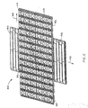
conveyor belt 80 constructed ofmodules 320 as in FIGS. 6A-B is shown in FIG. 9. The belt portion includes a series of six rows 82 of modules. Although each row could include a single module across its width, it is also possible to arrange the modules side by side and end to end in a bricklay pattern, for instance, to construct a belt of a desired length and width. To achieve the bricklay pattern, modules of different widths are used. As shown, each row includes a first set of hinge eyes 324 along a first end and a second set ofhinge eyes 325 along the opposite second end. A group offirst module pieces 322 are arranged side by side in the row and form at least some of the first and second hinge eyes. A complementary group ofsecond module pieces 323 are also arranged across the row and form other of the hinge eyes. The first set of hinge eyes of a row are interleaved with the second set of hinge eyes of an adjacent row. Hinge pins 83 extending through alignedapertures 26 in the interleaved hinge eyes connect the first and second module pieces together and pivotably connect adjacent rows together into a modular conveyor belt. The belt extends through its thickness from a top article-engaging surface 84 to an opposite bottom surface, which includes drive structure for engagement with a drive element such as a toothed sprocket (not shown).Seams 86 are formed between adjacent side-by-side modules in each row. Thus, the conveyor belt of FIG. 9 is formed of a top layer of second module pieces arranged in a bricklay pattern stacked on a coextensive bottom layer of first module pieces, with roller components sandwiched between the layers. Because this version of belt is reversible, a salient portion of each roller extends above the top surface and below the bottom surface. - Although the two layers could each be made in identical bricklay patterns in which each top module piece resides exclusively on a corresponding bottom module piece, the two layers could be laid out in different bricklay patterns, as illustrated in FIG. 10 for a portion of one row constructed of module pieces such as those in FIGS. 1 and 2. In this arrangement, second module pieces 23A and 23B in the top layer have a
seam 88 between them.First module pieces 22A, 22B, 22C forming the bottom layer havebottom seams 89 between side-by-side first module pieces. But the bricklay patterns of the top and bottom layers are such that theseams 88 on the top layer do not coincide with theseams 89 on the bottom layer. Thus, the second module piece 23A of the top layer mates with portions of thefirst module pieces 22A and 22B of the bottom layer. With the top and bottom seams offset laterally in this manner, seams extending all the way through the thickness of the belt are avoided, and the beam strength of the belt is increased. - One use for a modular belt made of belt modules such as the split roller-ball modules of FIGS. 5A-D is in the
conveyor system 400 of FIG. 11. The conveyor system includes an upper roller-ball conveyor belt 402 traveling in the direction ofarrow 404. A secondlower belt 406, such as a modular plastic conveyor belt topped with a high-friction surface 408, is positioned just below the conveyor belt so as to contact the salient portions of theroller balls 258 protruding through the bottom of the upper belt. (Suitable high-friction belts include the Series 900 Flat Friction Top and the Series 1100 Flush Grid Friction Top belts manufactured and sold by Intralox, Inc. of Harahan, Louisiana, USA.) In a preferred arrangement, the two belts are perpendicular to each other. While the lower belt is driven in the direction of arrow 410, the frictional contact between its high-friction surface and the bottoms of the roller balls in the upper belt rotates the balls generally in the direction of arrow 412. Articles, such asmail envelopes 414, conveyed on the upper belt are moved across the upper belt by the rotating roller balls. Thus, this conveyor could be used to align articles along one side of a belt or to transfer articles off the side of a belt. (Belt sideguards or conveyor frame side rails or conveyor off-transfer plates are not shown for simplicity.) Similarly, a belt such as the cylindrical roller-top belt of FIG. 9 could be used to align articles along one side of the belt in conjunction with a lower frictional belt or stationary wear surfaces beneath the roller-top belt in contact with the rollers protruding through the bottom surface of the belt. The rollers can be oriented all in the same oblique direction as in FIG. 9 to align articles along one side of the belt, or in one oblique direction on half the belt and the mirror-image direction on the other half to align articles along both sides or at the middle of the belt. With the axes of the rollers perpendicular to the direction of belt travel, the rollers can serve to separate conveyed articles by accelerating them as they come in contact with portions of the conveying path in which the rollers are in frictional rolling contact with wear surface material or the like. - Although the invention has been described in detail with respect to preferred versions, even other version are possible. A wide variety of top article-engaging module pieces could be mixed and matched with an equally wide variety of base pieces. Flights, buckets, textured surfaces, and non-planar surfaces are examples of just some of the customized top pieces that could be made. Base pieces that accommodate a variety of sprockets or with various strength or friction characteristics could be made and combined with the variety of top pieces mentioned in this versatile split-module arrangement. Components other than cylindrical or spherical rollers could be retained by the mated module pieces. Pop-up shoes, flights, brakes, and levers are just some examples of belt components that can be retained by mating the module pieces. In most of the described examples, the first and second pieces were essentially top and bottom pieces, but it would also be possible to split the pieces along surfaces other than one about midway between the top and bottom surfaces. It would also be possible to make one or the other of the module pieces form hinge eyes along only one end and to interfit into its mating piece by means of other structure, such as tabs, stubs, or snap-ins. The hinge eyes illustrated in the examples completely surround the perimeter of the hinge pins, but hinge eyes with an open eye wall are also possible. Thus, as these few additional examples suggest, the scope of the claims should not be limited to the preferred versions.
Claims (13)
- A split conveyor belt module (20; 120; 220; 320; 420) comprising a first set of hinge eyes (24; 124; 324) disposed along a first end of the module, a second set of hinge eyes (25; 125; 325) disposed along an opposite second end of the module, a top, article-supporting surface (32; 132; 232; 332; 432; 532) and an opposite bottom surface (233; 333; 433; 533), wherein the conveyor belt module is split into complementary pieces (22; 23; 122; 123; 222; 223; 322; 323; 422; 423; 522; 523), characterized in that:each of the complementary pieces includes at least a portion of the sets of hinge eyes and a planar face (34; 35; 134; 135; 234) opposite the top or bottom surface; andthe complementary pieces are stacked one atop the other so that the planar faces of the complementary pieces confront each other across a seam (36) formed through the split conveyor belt module between the top and bottom surfaces.
- A split conveyor belt module as in claim 1 wherein each of the complementary pieces includes at least one of the hinge eyes of the first set and at least one of the hinge eyes of the second set.
- A split conveyor belt module as in claim 1 or 2 wherein the split conveyor belt module is split into two complementary pieces; a first piece and a second piece.
- A split conveyor belt module as in claim 3 wherein the first piece forms a module base and the second piece stacks on the first piece and forms article-engaging structure.
- A split conveyor belt module as in claim 3 or 4 wherein the first piece and the second piece are substantially identical in structure.
- A split conveyor belt module as in claim 3 or 4 wherein the first piece and the second piece have the same number of hinge eyes along the first and second ends.
- A split conveyor belt module as in any preceding claim further comprising a component that is installable in or removable from the split conveyor belt module when the complementary pieces are unmated and that is retained in place in the split conveyor belt module when the complementary pieces are mated.
- A split conveyor belt module as in claim 7, wherein the component includes a roller (258; 366; 466; 561).
- A split conveyor belt module as in claim 7, wherein the component includes an axle (362; 475).
- A split conveyor belt module as in any of claims 3-9, wherein the first piece and the second piece are made of different material.
- A modular conveyor belt (80) comprising a plurality of the split conveyor belt modules of any preceding claims arranged end to end with the first set of hinge eyes of a module interleaved and aligned with the second set of hinge eyes of an adjacent module and a plurality of hinge pins (83) pivotably connecting adjacent modules through the interleaved set of hinge eyes into a modular conveyor belt.
- A conveyor belt, comprising a plurality of split conveyor modules as claimed in any of claims 1 to 10, and including
a bottom layer of belt module pieces having hinge eyes at opposite ends and arranged end to end and side to side in a bricklay pattern with seams (89) between adjacent side-by-side module pieces;
a top layer of belt module pieces having hinge eyes at opposite ends and arranged end to end and side to side in a bricklay pattern with seams (88) between adjacent side-by-side module pieces, wherein the top layer lies on the bottom layer; and
a plurality of hinge pins extending through the hinge eyes of the top and bottom layers to connect the layers together into a conveyor belt. - A conveyor belt as in claim 12, wherein the seams in the top layer are offset from the seams in the bottom layer to avoid continuous seams through both layers of the belt.
Applications Claiming Priority (2)
| Application Number | Priority Date | Filing Date | Title |
|---|---|---|---|
| US09/992,765 US6681922B2 (en) | 2001-11-06 | 2001-11-06 | Split belt modules in modular conveyer belts |
| US992765 | 2001-11-06 |
Publications (3)
| Publication Number | Publication Date |
|---|---|
| EP1316519A2 EP1316519A2 (en) | 2003-06-04 |
| EP1316519A3 EP1316519A3 (en) | 2003-08-13 |
| EP1316519B1 true EP1316519B1 (en) | 2007-08-29 |
Family
ID=25538717
Family Applications (1)
| Application Number | Title | Priority Date | Filing Date |
|---|---|---|---|
| EP02257274A Expired - Lifetime EP1316519B1 (en) | 2001-11-06 | 2002-10-18 | Split belt modules in modular conveyor belts |
Country Status (9)
| Country | Link |
|---|---|
| US (2) | US6681922B2 (en) |
| EP (1) | EP1316519B1 (en) |
| JP (1) | JP4198969B2 (en) |
| AT (1) | ATE371611T1 (en) |
| AU (1) | AU2002301405B2 (en) |
| CA (1) | CA2410359C (en) |
| DE (1) | DE60222080T2 (en) |
| DK (1) | DK1316519T3 (en) |
| ES (1) | ES2292698T3 (en) |
Families Citing this family (61)
| Publication number | Priority date | Publication date | Assignee | Title |
|---|---|---|---|---|
| US6681922B2 (en) * | 2001-11-06 | 2004-01-27 | The Laitram Corporation | Split belt modules in modular conveyer belts |
| US6571937B1 (en) * | 2002-09-13 | 2003-06-03 | The Laitram Corporation | Switch conveyor |
| US6874617B1 (en) * | 2003-09-26 | 2005-04-05 | Span Tech Llc | Modular link conveyor chain with rotatable article engaging assemblies |
| DE10354133A1 (en) * | 2003-11-19 | 2005-06-23 | Phoenix Ag | conveyor belt |
| US6968941B2 (en) * | 2003-11-21 | 2005-11-29 | Materials Handling Systems, Inc. | Apparatus and methods for conveying objects |
| JP4425000B2 (en) * | 2004-01-06 | 2010-03-03 | 株式会社ブリヂストン | Rubber member conveying device and rubber member supply system having the same |
| US6997306B2 (en) * | 2004-01-21 | 2006-02-14 | Laitram, L.L.C. | Conveyor belt modules with embedded rollers retained in the modules and associated method |
| JP3954040B2 (en) * | 2004-04-28 | 2007-08-08 | 株式会社椿本チエイン | Conveyor chain |
| ITMI20040881A1 (en) * | 2004-05-03 | 2004-08-03 | Regina Sud Spa | CONVEYOR EQUIPPED WITH NON-SLIP SUPPORT SURFACE AND METHOD FOR ITS MANUFACTURE |
| US7040480B2 (en) * | 2004-07-19 | 2006-05-09 | Laitram, L.L.C. | Zero back pressure conveyor |
| JP3930007B2 (en) * | 2004-09-03 | 2007-06-13 | 株式会社椿本チエイン | Conveyor chain |
| DE202004021736U1 (en) * | 2004-09-10 | 2010-10-21 | J.D. Theile Gmbh & Co. Kg | link chain |
| JP5085328B2 (en) * | 2004-09-28 | 2012-11-28 | レイトラム リミテッド ライアビリティー カンパニー | Apparatus and method for high speed conveyor switching |
| US8151978B2 (en) * | 2004-11-05 | 2012-04-10 | Rexnord Industries, Llc | Low backline pressure modular conveying assembly |
| CA2586296A1 (en) * | 2004-11-05 | 2006-06-15 | Standard Knapp Inc. | Case packer with a segmented drivable riding strip and segmented drivable riding strip therefore |
| JP3949685B2 (en) | 2004-12-24 | 2007-07-25 | 株式会社椿本チエイン | Multi-function conveyor chain |
| CN101094799B (en) * | 2005-01-03 | 2012-07-25 | 莱特拉姆有限责任公司 | Conveyor having a conveyor belt with flights, including segmented flights for gapless end transfer |
| US7191894B2 (en) * | 2005-04-04 | 2007-03-20 | Laitram, L.L.C. | Variable angled-roller belt and conveyor |
| JP4067534B2 (en) * | 2005-04-22 | 2008-03-26 | 株式会社椿本チエイン | Conveyor chain |
| US7249671B2 (en) * | 2005-05-06 | 2007-07-31 | Laitram, L.L.C. | Roller-belt conveyor for accumulating and moving articles laterally across the conveyor |
| US7344018B2 (en) * | 2005-05-06 | 2008-03-18 | Laitram, L.L.C. | Conveyor and method for diverting closely spaced articles |
| JP4173151B2 (en) | 2005-05-23 | 2008-10-29 | 株式会社椿本チエイン | Conveyor chain |
| US7252192B2 (en) * | 2005-07-01 | 2007-08-07 | Rexnord Industries, Llc | Side-flexing conveyor module with detachable roller assembly |
| WO2007028102A2 (en) * | 2005-09-02 | 2007-03-08 | Span Tech Llc | Wear-resistant connector for a modular link conveyor belt |
| US7364038B2 (en) * | 2005-09-20 | 2008-04-29 | Uni-Chains A/S | Conveyor belt link incorporating one or more rollers |
| US7357246B2 (en) * | 2005-09-23 | 2008-04-15 | Laitram, L.L.C. | Belt conveyor having self-clearing flights |
| BRPI0621100A2 (en) * | 2005-11-21 | 2011-11-29 | Laitram Llc | switch and switch for distributing articles received from an inbound conveyor belt to a plurality of outbound conveyor belts |
| DE102006004807A1 (en) * | 2006-01-24 | 2007-08-02 | Hauni Maschinenbau Ag | Conveyor track or belt without rollers has linked elements with apertures for driving from top of bottom faces |
| DE102006004808A1 (en) * | 2006-01-24 | 2007-08-02 | Hauni Maschinenbau Ag | Chain conveyor as curved and roller free conveyor chain, comprises multiple carrying elements, which are movably connected with each other by intermediate elements, which are connected with carrying elements |
| FR2897341B1 (en) * | 2006-02-13 | 2008-04-25 | Sidel Participations | METHOD AND INSTALLATION FOR THE GROUPING OF PALLETIZABLE PRODUCTS. |
| US7284653B2 (en) * | 2006-03-23 | 2007-10-23 | Laitram, L.L.C. | Sorter belt conveyor |
| DK2007660T3 (en) * | 2006-04-03 | 2011-09-26 | Span Tech Llc | Conveyor with components for transporting powder coated products |
| US7198148B1 (en) * | 2006-06-28 | 2007-04-03 | Habasit Ag | Modular conveyor belt with cam flights |
| US7237670B1 (en) | 2006-07-21 | 2007-07-03 | Laitram, L.L.C. | Transverse-roller belt conveyor |
| US7360643B1 (en) * | 2007-03-20 | 2008-04-22 | Habasit Ag | Electroconductive modular belt |
| US7540368B2 (en) * | 2007-05-01 | 2009-06-02 | Laitram, L.L.C. | Transverse-roller belts and modules |
| US7556136B2 (en) * | 2007-10-11 | 2009-07-07 | Laitram, L.L.C. | Conveyor belt module with retained rollers |
| US20110284347A1 (en) * | 2009-01-12 | 2011-11-24 | Laitram, L.L.C. | Metal-fused plastic conveyor belt components and methods of making |
| US8172069B2 (en) * | 2009-03-26 | 2012-05-08 | Habasit Ag | Diverter ball conveyor |
| JP5052644B2 (en) * | 2010-04-22 | 2012-10-17 | 株式会社椿本チエイン | Conveyor equipment |
| JP5377410B2 (en) | 2010-05-28 | 2013-12-25 | 株式会社椿本チエイン | Conveyor chain |
| JP5455849B2 (en) * | 2010-08-30 | 2014-03-26 | 株式会社椿本チエイン | Sorting device |
| ITMI20110095U1 (en) * | 2011-03-23 | 2012-09-24 | Neptun S R L | PERFECT ANCHORS FOR CONVEYOR BELTS. |
| US8881890B2 (en) * | 2011-05-23 | 2014-11-11 | Laitram, L.L.C. | Conveyor belt module with fixed axles |
| DK177377B1 (en) * | 2011-07-05 | 2013-02-25 | Ammeraal Beltech Modular As | Modular belt module |
| NL2007860C2 (en) | 2011-11-24 | 2013-05-27 | Rexnord Flattop Europe Bv | MODULAR TRANSPORT MAT AND TRANSPORTER WITH A MODULAR TRANSPORT MAT. |
| MX360265B (en) | 2012-07-18 | 2018-10-26 | Laitram Llc | Conveyor belt including chocking module. |
| JP2014118281A (en) | 2012-12-18 | 2014-06-30 | Tsubakimoto Chain Co | Chain transport device |
| EP2943423B1 (en) | 2013-01-08 | 2020-05-06 | Regal Beloit America, Inc. | Modular conveying systems and methods |
| ES2523470B1 (en) * | 2013-04-22 | 2015-05-20 | Magdalena NÚÑEZ BAJO | TRANSPORT CHAIN TRANSFER SYSTEM WITH GROOVED PUSHERS |
| EP2927162B1 (en) | 2014-03-31 | 2016-05-25 | Forbo Siegling Gmbh | Module member for a conveyor belt, and conveyor belt made of module members that are flexibly connected to each other |
| CN106660713B (en) | 2014-06-25 | 2019-12-06 | 莱特拉姆有限责任公司 | Multi-directional roller assembly for a conveyor |
| EP3150517A1 (en) * | 2015-09-30 | 2017-04-05 | Logi Concept Engineering B.V. | Conveyor belt |
| CN106628823A (en) * | 2016-10-10 | 2017-05-10 | 金锋馥(滁州)输送机械有限公司 | Mesh belt type distributing and combining device |
| US10988318B2 (en) | 2017-05-17 | 2021-04-27 | Laitram, L.L.C. | Centrifugal dewatering conveyor system |
| EP3653545A1 (en) * | 2018-11-13 | 2020-05-20 | Logevo AB | A conveyor junction |
| EP3862298A1 (en) * | 2020-02-04 | 2021-08-11 | Ammeraal Beltech Modular A/S | Modular belt link as well as a conveyor belt assembled from a plurality of such belt links |
| WO2022005454A1 (en) * | 2020-06-30 | 2022-01-06 | Cumbria Enterprises, Llc | Modular omnidirectional hygienic conveyor belt and directional control system |
| WO2022072581A1 (en) * | 2020-10-01 | 2022-04-07 | Laitram, L.L.C. | Modular conveyor belt with dedicated access module |
| DE102021129382A1 (en) | 2020-11-12 | 2022-05-12 | Dücker Group GmbH | Angle transfer with roller chain |
| DE102021115517A1 (en) * | 2021-06-16 | 2022-12-22 | Kabelschlepp GmbH-Hünsborn | Hinged tape with double plate |
Family Cites Families (28)
| Publication number | Priority date | Publication date | Assignee | Title |
|---|---|---|---|---|
| US2954113A (en) | 1957-01-09 | 1960-09-27 | Chain Belt Co | Conveyer chain attachments |
| IT8134921V0 (en) | 1981-12-22 | 1981-12-22 | Marbett S N C Di Mariani Betta | CONVEYOR CHAIN WITH ANTI-WEAR COATING |
| US4556142A (en) | 1983-01-12 | 1985-12-03 | The Laitram Corporation | Lightweight modular conveyor belt |
| US4832183A (en) | 1984-08-20 | 1989-05-23 | The Laitram Corporation | Conveyor belt having insertable & selectable conveying member |
| EP0215983A1 (en) | 1985-08-29 | 1987-04-01 | The Laitram Corporation | End to end moulded conveyor belt module |
| IT222736Z2 (en) | 1991-09-19 | 1995-04-24 | Regina Sud Spa | CONTINUOUS ROLLER CONVEYOR |
| US5238099A (en) | 1992-08-04 | 1993-08-24 | Premark Feg Corporation | Conveying system |
| US5377819A (en) * | 1993-07-02 | 1995-01-03 | The Laitram Corporation | Conveyor apparatus and method |
| US5361893A (en) * | 1993-11-18 | 1994-11-08 | The Laitram Corporation | High friction plastic conveyor belts having modular links formed by two integrated plastic materials |
| KR100230232B1 (en) * | 1994-06-30 | 1999-11-15 | 윤종용 | Optical disk recording and reproducing device for plural user |
| US5469956A (en) | 1995-01-20 | 1995-11-28 | The Laitram Corporation | Modular conveyor belt and flight members therefor |
| US5921379A (en) * | 1996-01-23 | 1999-07-13 | The Laitram Corporation | Modular conveyor belt suitable for following straight or curved paths |
| US5947361A (en) * | 1996-07-25 | 1999-09-07 | Emo Elektromotorenwerk Kamenz Gmbh | Apparatus for transporting fabrics and web-shaped material with an electric drive device |
| NL1005979C2 (en) | 1997-05-06 | 1998-11-09 | Ashworth Jonge Poerink Bv | Conveyor belt comprising panels joined by hinge connections |
| NL1010040C2 (en) * | 1998-09-09 | 2000-03-10 | Mcc Nederland | Transport mat built from plastic modules and a module for such a transport mat. |
| US6148990A (en) * | 1998-11-02 | 2000-11-21 | The Laitram Corporation | Modular roller-top conveyor belt |
| US6494312B2 (en) * | 1998-11-02 | 2002-12-17 | The Laitram Corporation | Modular roller-top conveyor belt with obliquely-arranged rollers |
| EP1050492B1 (en) * | 1999-05-05 | 2004-10-06 | Habasit AG | Conveying device with a modular conveyor belt and at least one driving sprocket wheel |
| US6318544B1 (en) * | 1999-11-05 | 2001-11-20 | The Laitram Corporation | Changing the characteristics of an article-conveying belt surface on a running conveyor |
| US6347699B1 (en) * | 1999-11-08 | 2002-02-19 | Earl Ramsey | Conveyor chain link |
| US6398015B1 (en) * | 2000-05-03 | 2002-06-04 | The Laitram Corporation | Roller-top conveyor belt and modules with closely-spaced rollers |
| JP4010755B2 (en) * | 2000-08-31 | 2007-11-21 | 株式会社椿本チエイン | Conveyor chain |
| US6444466B1 (en) * | 2001-05-10 | 2002-09-03 | Isis Pharmaceuticals, Inc. | Antisense modulation of helicase-moi expression |
| JP3513616B2 (en) * | 2001-06-28 | 2004-03-31 | 山久チヱイン株式会社 | Cross conveyor chain device |
| US6681922B2 (en) * | 2001-11-06 | 2004-01-27 | The Laitram Corporation | Split belt modules in modular conveyer belts |
| US6648129B2 (en) * | 2001-11-08 | 2003-11-18 | The Laitram Corporation | Abrasion-resistant two-material hinge pin in a modular plastic conveyor belt |
| US6705460B2 (en) * | 2002-04-23 | 2004-03-16 | Laitram L.L.C. | Modular conveyor belt |
| US6571937B1 (en) * | 2002-09-13 | 2003-06-03 | The Laitram Corporation | Switch conveyor |
-
2001
- 2001-11-06 US US09/992,765 patent/US6681922B2/en not_active Expired - Lifetime
-
2002
- 2002-10-09 AU AU2002301405A patent/AU2002301405B2/en not_active Ceased
- 2002-10-18 AT AT02257274T patent/ATE371611T1/en not_active IP Right Cessation
- 2002-10-18 DK DK02257274T patent/DK1316519T3/en active
- 2002-10-18 DE DE60222080T patent/DE60222080T2/en not_active Expired - Lifetime
- 2002-10-18 ES ES02257274T patent/ES2292698T3/en not_active Expired - Lifetime
- 2002-10-18 EP EP02257274A patent/EP1316519B1/en not_active Expired - Lifetime
- 2002-10-30 CA CA2410359A patent/CA2410359C/en not_active Expired - Fee Related
- 2002-11-01 JP JP2002320394A patent/JP4198969B2/en not_active Expired - Fee Related
-
2004
- 2004-01-16 US US10/707,849 patent/US6986420B2/en not_active Expired - Lifetime
Also Published As
| Publication number | Publication date |
|---|---|
| AU2002301405B2 (en) | 2009-06-18 |
| JP4198969B2 (en) | 2008-12-17 |
| US20040129539A1 (en) | 2004-07-08 |
| DE60222080D1 (en) | 2007-10-11 |
| JP2003182829A (en) | 2003-07-03 |
| EP1316519A3 (en) | 2003-08-13 |
| US6986420B2 (en) | 2006-01-17 |
| DK1316519T3 (en) | 2008-01-21 |
| CA2410359C (en) | 2011-06-14 |
| DE60222080T2 (en) | 2008-05-21 |
| ATE371611T1 (en) | 2007-09-15 |
| US20030085106A1 (en) | 2003-05-08 |
| EP1316519A2 (en) | 2003-06-04 |
| US6681922B2 (en) | 2004-01-27 |
| ES2292698T3 (en) | 2008-03-16 |
| CA2410359A1 (en) | 2003-05-06 |
Similar Documents
| Publication | Publication Date | Title |
|---|---|---|
| EP1316519B1 (en) | Split belt modules in modular conveyor belts | |
| US7540368B2 (en) | Transverse-roller belts and modules | |
| EP2475600B1 (en) | Conveyors, belts, and modules with actuated rollers | |
| EP1868924B1 (en) | Belt conveyor with variable angled rollers | |
| JP5379691B2 (en) | Conveyor belt with rollers supported between modules | |
| US6148990A (en) | Modular roller-top conveyor belt | |
| EP2621835B1 (en) | Conveyor, belt, and module having multi-directional wheels | |
| US8225922B1 (en) | Transverse driven-roller belt and conveyor | |
| EP2877413B1 (en) | Modular conveyor belt with extended raised ribs | |
| WO2001083338A1 (en) | Roller-top conveyor belt and modules with closely-spaced rollers | |
| US7997404B2 (en) | Conveyor belt with intermodular supported spheres | |
| US7357246B2 (en) | Belt conveyor having self-clearing flights | |
| US7527145B2 (en) | Low-friction conveyor | |
| US11905118B2 (en) | Roller belt with support edges |
Legal Events
| Date | Code | Title | Description |
|---|---|---|---|
| PUAI | Public reference made under article 153(3) epc to a published international application that has entered the european phase |
Free format text: ORIGINAL CODE: 0009012 |
|
| AK | Designated contracting states |
Designated state(s): AT BE BG CH CY CZ DE DK EE ES FI FR GB GR IE IT LI LU MC NL PT SE SK TR |
|
| AX | Request for extension of the european patent |
Extension state: AL LT LV MK RO SI |
|
| PUAL | Search report despatched |
Free format text: ORIGINAL CODE: 0009013 |
|
| AK | Designated contracting states |
Designated state(s): AT BE BG CH CY CZ DE DK EE ES FI FR GB GR IE IT LI LU MC NL PT SE SK TR |
|
| AX | Request for extension of the european patent |
Extension state: AL LT LV MK RO SI |
|
| RAP1 | Party data changed (applicant data changed or rights of an application transferred) |
Owner name: LAITRAM L.L.C. |
|
| 17P | Request for examination filed |
Effective date: 20040128 |
|
| AKX | Designation fees paid |
Designated state(s): AT BE BG CH CY CZ DE DK EE ES FI FR GB GR IE IT LI LU MC NL PT SE SK TR |
|
| GRAP | Despatch of communication of intention to grant a patent |
Free format text: ORIGINAL CODE: EPIDOSNIGR1 |
|
| RIN1 | Information on inventor provided before grant (corrected) |
Inventor name: SEDLACEK, KYLE J. Inventor name: WEISER, DAVID C. Inventor name: JONES, RYAN M. Inventor name: CORLEY, ANDREW A. Inventor name: MARSHALL, ANGELA L. |
|
| GRAS | Grant fee paid |
Free format text: ORIGINAL CODE: EPIDOSNIGR3 |
|
| GRAA | (expected) grant |
Free format text: ORIGINAL CODE: 0009210 |
|
| AK | Designated contracting states |
Kind code of ref document: B1 Designated state(s): AT BE BG CH CY CZ DE DK EE ES FI FR GB GR IE IT LI LU MC NL PT SE SK TR |
|
| REG | Reference to a national code |
Ref country code: GB Ref legal event code: FG4D |
|
| REG | Reference to a national code |
Ref country code: CH Ref legal event code: EP Ref country code: CH Ref legal event code: NV Representative=s name: AMMANN PATENTANWAELTE AG BERN |
|
| REG | Reference to a national code |
Ref country code: IE Ref legal event code: FG4D |
|
| REF | Corresponds to: |
Ref document number: 60222080 Country of ref document: DE Date of ref document: 20071011 Kind code of ref document: P |
|
| ET | Fr: translation filed | ||
| REG | Reference to a national code |
Ref country code: DK Ref legal event code: T3 |
|
| PG25 | Lapsed in a contracting state [announced via postgrant information from national office to epo] |
Ref country code: FI Free format text: LAPSE BECAUSE OF FAILURE TO SUBMIT A TRANSLATION OF THE DESCRIPTION OR TO PAY THE FEE WITHIN THE PRESCRIBED TIME-LIMIT Effective date: 20070829 |
|
| PG25 | Lapsed in a contracting state [announced via postgrant information from national office to epo] |
Ref country code: AT Free format text: LAPSE BECAUSE OF FAILURE TO SUBMIT A TRANSLATION OF THE DESCRIPTION OR TO PAY THE FEE WITHIN THE PRESCRIBED TIME-LIMIT Effective date: 20070829 |
|
| REG | Reference to a national code |
Ref country code: ES Ref legal event code: FG2A Ref document number: 2292698 Country of ref document: ES Kind code of ref document: T3 |
|
| PG25 | Lapsed in a contracting state [announced via postgrant information from national office to epo] |
Ref country code: BE Free format text: LAPSE BECAUSE OF FAILURE TO SUBMIT A TRANSLATION OF THE DESCRIPTION OR TO PAY THE FEE WITHIN THE PRESCRIBED TIME-LIMIT Effective date: 20070829 |
|
| PG25 | Lapsed in a contracting state [announced via postgrant information from national office to epo] |
Ref country code: GR Free format text: LAPSE BECAUSE OF FAILURE TO SUBMIT A TRANSLATION OF THE DESCRIPTION OR TO PAY THE FEE WITHIN THE PRESCRIBED TIME-LIMIT Effective date: 20071130 |
|
| PG25 | Lapsed in a contracting state [announced via postgrant information from national office to epo] |
Ref country code: SK Free format text: LAPSE BECAUSE OF FAILURE TO SUBMIT A TRANSLATION OF THE DESCRIPTION OR TO PAY THE FEE WITHIN THE PRESCRIBED TIME-LIMIT Effective date: 20070829 Ref country code: CZ Free format text: LAPSE BECAUSE OF FAILURE TO SUBMIT A TRANSLATION OF THE DESCRIPTION OR TO PAY THE FEE WITHIN THE PRESCRIBED TIME-LIMIT Effective date: 20070829 Ref country code: MC Free format text: LAPSE BECAUSE OF NON-PAYMENT OF DUE FEES Effective date: 20071031 Ref country code: PT Free format text: LAPSE BECAUSE OF FAILURE TO SUBMIT A TRANSLATION OF THE DESCRIPTION OR TO PAY THE FEE WITHIN THE PRESCRIBED TIME-LIMIT Effective date: 20080129 |
|
| PG25 | Lapsed in a contracting state [announced via postgrant information from national office to epo] |
Ref country code: SE Free format text: LAPSE BECAUSE OF FAILURE TO SUBMIT A TRANSLATION OF THE DESCRIPTION OR TO PAY THE FEE WITHIN THE PRESCRIBED TIME-LIMIT Effective date: 20071129 |
|
| PLBE | No opposition filed within time limit |
Free format text: ORIGINAL CODE: 0009261 |
|
| STAA | Information on the status of an ep patent application or granted ep patent |
Free format text: STATUS: NO OPPOSITION FILED WITHIN TIME LIMIT |
|
| 26N | No opposition filed |
Effective date: 20080530 |
|
| PG25 | Lapsed in a contracting state [announced via postgrant information from national office to epo] |
Ref country code: IE Free format text: LAPSE BECAUSE OF NON-PAYMENT OF DUE FEES Effective date: 20071018 |
|
| PG25 | Lapsed in a contracting state [announced via postgrant information from national office to epo] |
Ref country code: EE Free format text: LAPSE BECAUSE OF FAILURE TO SUBMIT A TRANSLATION OF THE DESCRIPTION OR TO PAY THE FEE WITHIN THE PRESCRIBED TIME-LIMIT Effective date: 20070829 |
|
| PG25 | Lapsed in a contracting state [announced via postgrant information from national office to epo] |
Ref country code: CY Free format text: LAPSE BECAUSE OF FAILURE TO SUBMIT A TRANSLATION OF THE DESCRIPTION OR TO PAY THE FEE WITHIN THE PRESCRIBED TIME-LIMIT Effective date: 20070829 |
|
| PG25 | Lapsed in a contracting state [announced via postgrant information from national office to epo] |
Ref country code: BG Free format text: LAPSE BECAUSE OF FAILURE TO SUBMIT A TRANSLATION OF THE DESCRIPTION OR TO PAY THE FEE WITHIN THE PRESCRIBED TIME-LIMIT Effective date: 20071129 Ref country code: LU Free format text: LAPSE BECAUSE OF NON-PAYMENT OF DUE FEES Effective date: 20071018 |
|
| PG25 | Lapsed in a contracting state [announced via postgrant information from national office to epo] |
Ref country code: TR Free format text: LAPSE BECAUSE OF FAILURE TO SUBMIT A TRANSLATION OF THE DESCRIPTION OR TO PAY THE FEE WITHIN THE PRESCRIBED TIME-LIMIT Effective date: 20070829 |
|
| PGFP | Annual fee paid to national office [announced via postgrant information from national office to epo] |
Ref country code: GB Payment date: 20130925 Year of fee payment: 12 |
|
| PGFP | Annual fee paid to national office [announced via postgrant information from national office to epo] |
Ref country code: FR Payment date: 20130924 Year of fee payment: 12 |
|
| PGFP | Annual fee paid to national office [announced via postgrant information from national office to epo] |
Ref country code: NL Payment date: 20131010 Year of fee payment: 12 Ref country code: ES Payment date: 20131022 Year of fee payment: 12 |
|
| REG | Reference to a national code |
Ref country code: NL Ref legal event code: V1 Effective date: 20150501 |
|
| GBPC | Gb: european patent ceased through non-payment of renewal fee |
Effective date: 20141018 |
|
| PG25 | Lapsed in a contracting state [announced via postgrant information from national office to epo] |
Ref country code: GB Free format text: LAPSE BECAUSE OF NON-PAYMENT OF DUE FEES Effective date: 20141018 |
|
| REG | Reference to a national code |
Ref country code: FR Ref legal event code: ST Effective date: 20150630 |
|
| PG25 | Lapsed in a contracting state [announced via postgrant information from national office to epo] |
Ref country code: FR Free format text: LAPSE BECAUSE OF NON-PAYMENT OF DUE FEES Effective date: 20141031 Ref country code: NL Free format text: LAPSE BECAUSE OF NON-PAYMENT OF DUE FEES Effective date: 20150501 |
|
| REG | Reference to a national code |
Ref country code: ES Ref legal event code: FD2A Effective date: 20160509 |
|
| PG25 | Lapsed in a contracting state [announced via postgrant information from national office to epo] |
Ref country code: ES Free format text: LAPSE BECAUSE OF NON-PAYMENT OF DUE FEES Effective date: 20141019 |
|
| PGFP | Annual fee paid to national office [announced via postgrant information from national office to epo] |
Ref country code: DK Payment date: 20200925 Year of fee payment: 19 |
|
| PGFP | Annual fee paid to national office [announced via postgrant information from national office to epo] |
Ref country code: CH Payment date: 20200918 Year of fee payment: 19 |
|
| PGFP | Annual fee paid to national office [announced via postgrant information from national office to epo] |
Ref country code: DE Payment date: 20200916 Year of fee payment: 19 Ref country code: IT Payment date: 20201014 Year of fee payment: 19 |
|
| REG | Reference to a national code |
Ref country code: DE Ref legal event code: R119 Ref document number: 60222080 Country of ref document: DE |
|
| REG | Reference to a national code |
Ref country code: DK Ref legal event code: EBP Effective date: 20211031 |
|
| REG | Reference to a national code |
Ref country code: CH Ref legal event code: PL |
|
| PG25 | Lapsed in a contracting state [announced via postgrant information from national office to epo] |
Ref country code: DE Free format text: LAPSE BECAUSE OF NON-PAYMENT OF DUE FEES Effective date: 20220503 |
|
| PG25 | Lapsed in a contracting state [announced via postgrant information from national office to epo] |
Ref country code: LI Free format text: LAPSE BECAUSE OF NON-PAYMENT OF DUE FEES Effective date: 20211031 Ref country code: CH Free format text: LAPSE BECAUSE OF NON-PAYMENT OF DUE FEES Effective date: 20211031 |
|
| PG25 | Lapsed in a contracting state [announced via postgrant information from national office to epo] |
Ref country code: IT Free format text: LAPSE BECAUSE OF NON-PAYMENT OF DUE FEES Effective date: 20211018 Ref country code: DK Free format text: LAPSE BECAUSE OF NON-PAYMENT OF DUE FEES Effective date: 20211031 |