EP1316474A2 - Automatic directional control system for vehicle headlights - Google Patents
Automatic directional control system for vehicle headlights Download PDFInfo
- Publication number
- EP1316474A2 EP1316474A2 EP02257557A EP02257557A EP1316474A2 EP 1316474 A2 EP1316474 A2 EP 1316474A2 EP 02257557 A EP02257557 A EP 02257557A EP 02257557 A EP02257557 A EP 02257557A EP 1316474 A2 EP1316474 A2 EP 1316474A2
- Authority
- EP
- European Patent Office
- Prior art keywords
- headlight
- vehicle
- controller
- control system
- output signal
- Prior art date
- Legal status (The legal status is an assumption and is not a legal conclusion. Google has not performed a legal analysis and makes no representation as to the accuracy of the status listed.)
- Withdrawn
Links
- 230000008859 change Effects 0.000 claims abstract description 32
- 239000000725 suspension Substances 0.000 claims abstract description 20
- 230000000694 effects Effects 0.000 claims abstract description 13
- 238000000034 method Methods 0.000 abstract description 3
- 230000003287 optical effect Effects 0.000 description 11
- 230000004044 response Effects 0.000 description 6
- 230000006870 function Effects 0.000 description 4
- 230000001133 acceleration Effects 0.000 description 2
- 238000004364 calculation method Methods 0.000 description 2
- 230000005355 Hall effect Effects 0.000 description 1
- 230000003213 activating effect Effects 0.000 description 1
- 230000004075 alteration Effects 0.000 description 1
- 239000002131 composite material Substances 0.000 description 1
- 238000011217 control strategy Methods 0.000 description 1
- 230000003247 decreasing effect Effects 0.000 description 1
- 230000007812 deficiency Effects 0.000 description 1
- 230000002950 deficient Effects 0.000 description 1
- 238000010586 diagram Methods 0.000 description 1
- 230000004313 glare Effects 0.000 description 1
- 229910052736 halogen Inorganic materials 0.000 description 1
- 150000002367 halogens Chemical class 0.000 description 1
- 238000005286 illumination Methods 0.000 description 1
- 230000007246 mechanism Effects 0.000 description 1
- 230000008569 process Effects 0.000 description 1
- 230000007704 transition Effects 0.000 description 1
Images



Classifications
-
- B—PERFORMING OPERATIONS; TRANSPORTING
- B60—VEHICLES IN GENERAL
- B60Q—ARRANGEMENT OF SIGNALLING OR LIGHTING DEVICES, THE MOUNTING OR SUPPORTING THEREOF OR CIRCUITS THEREFOR, FOR VEHICLES IN GENERAL
- B60Q1/00—Arrangement of optical signalling or lighting devices, the mounting or supporting thereof or circuits therefor
- B60Q1/02—Arrangement of optical signalling or lighting devices, the mounting or supporting thereof or circuits therefor the devices being primarily intended to illuminate the way ahead or to illuminate other areas of way or environments
- B60Q1/04—Arrangement of optical signalling or lighting devices, the mounting or supporting thereof or circuits therefor the devices being primarily intended to illuminate the way ahead or to illuminate other areas of way or environments the devices being headlights
- B60Q1/06—Arrangement of optical signalling or lighting devices, the mounting or supporting thereof or circuits therefor the devices being primarily intended to illuminate the way ahead or to illuminate other areas of way or environments the devices being headlights adjustable, e.g. remotely-controlled from inside vehicle
- B60Q1/08—Arrangement of optical signalling or lighting devices, the mounting or supporting thereof or circuits therefor the devices being primarily intended to illuminate the way ahead or to illuminate other areas of way or environments the devices being headlights adjustable, e.g. remotely-controlled from inside vehicle automatically
- B60Q1/12—Arrangement of optical signalling or lighting devices, the mounting or supporting thereof or circuits therefor the devices being primarily intended to illuminate the way ahead or to illuminate other areas of way or environments the devices being headlights adjustable, e.g. remotely-controlled from inside vehicle automatically due to steering position
-
- B—PERFORMING OPERATIONS; TRANSPORTING
- B60—VEHICLES IN GENERAL
- B60Q—ARRANGEMENT OF SIGNALLING OR LIGHTING DEVICES, THE MOUNTING OR SUPPORTING THEREOF OR CIRCUITS THEREFOR, FOR VEHICLES IN GENERAL
- B60Q1/00—Arrangement of optical signalling or lighting devices, the mounting or supporting thereof or circuits therefor
- B60Q1/02—Arrangement of optical signalling or lighting devices, the mounting or supporting thereof or circuits therefor the devices being primarily intended to illuminate the way ahead or to illuminate other areas of way or environments
- B60Q1/04—Arrangement of optical signalling or lighting devices, the mounting or supporting thereof or circuits therefor the devices being primarily intended to illuminate the way ahead or to illuminate other areas of way or environments the devices being headlights
- B60Q1/06—Arrangement of optical signalling or lighting devices, the mounting or supporting thereof or circuits therefor the devices being primarily intended to illuminate the way ahead or to illuminate other areas of way or environments the devices being headlights adjustable, e.g. remotely-controlled from inside vehicle
- B60Q1/08—Arrangement of optical signalling or lighting devices, the mounting or supporting thereof or circuits therefor the devices being primarily intended to illuminate the way ahead or to illuminate other areas of way or environments the devices being headlights adjustable, e.g. remotely-controlled from inside vehicle automatically
- B60Q1/10—Arrangement of optical signalling or lighting devices, the mounting or supporting thereof or circuits therefor the devices being primarily intended to illuminate the way ahead or to illuminate other areas of way or environments the devices being headlights adjustable, e.g. remotely-controlled from inside vehicle automatically due to vehicle inclination, e.g. due to load distribution
-
- B—PERFORMING OPERATIONS; TRANSPORTING
- B60—VEHICLES IN GENERAL
- B60Q—ARRANGEMENT OF SIGNALLING OR LIGHTING DEVICES, THE MOUNTING OR SUPPORTING THEREOF OR CIRCUITS THEREFOR, FOR VEHICLES IN GENERAL
- B60Q1/00—Arrangement of optical signalling or lighting devices, the mounting or supporting thereof or circuits therefor
- B60Q1/02—Arrangement of optical signalling or lighting devices, the mounting or supporting thereof or circuits therefor the devices being primarily intended to illuminate the way ahead or to illuminate other areas of way or environments
- B60Q1/04—Arrangement of optical signalling or lighting devices, the mounting or supporting thereof or circuits therefor the devices being primarily intended to illuminate the way ahead or to illuminate other areas of way or environments the devices being headlights
- B60Q1/18—Arrangement of optical signalling or lighting devices, the mounting or supporting thereof or circuits therefor the devices being primarily intended to illuminate the way ahead or to illuminate other areas of way or environments the devices being headlights being additional front lights
-
- B—PERFORMING OPERATIONS; TRANSPORTING
- B60—VEHICLES IN GENERAL
- B60Q—ARRANGEMENT OF SIGNALLING OR LIGHTING DEVICES, THE MOUNTING OR SUPPORTING THEREOF OR CIRCUITS THEREFOR, FOR VEHICLES IN GENERAL
- B60Q11/00—Arrangement of monitoring devices for devices provided for in groups B60Q1/00 - B60Q9/00
-
- G—PHYSICS
- G01—MEASURING; TESTING
- G01M—TESTING STATIC OR DYNAMIC BALANCE OF MACHINES OR STRUCTURES; TESTING OF STRUCTURES OR APPARATUS, NOT OTHERWISE PROVIDED FOR
- G01M11/00—Testing of optical apparatus; Testing structures by optical methods not otherwise provided for
- G01M11/02—Testing optical properties
- G01M11/06—Testing the alignment of vehicle headlight devices
- G01M11/068—Testing the alignment of vehicle headlight devices with part of the measurements done from inside the vehicle
-
- B—PERFORMING OPERATIONS; TRANSPORTING
- B60—VEHICLES IN GENERAL
- B60Q—ARRANGEMENT OF SIGNALLING OR LIGHTING DEVICES, THE MOUNTING OR SUPPORTING THEREOF OR CIRCUITS THEREFOR, FOR VEHICLES IN GENERAL
- B60Q2200/00—Special features or arrangements of vehicle headlamps
- B60Q2200/30—Special arrangements for adjusting headlamps, e.g. means for transmitting the movements for adjusting the lamps
- B60Q2200/38—Automatic calibration of motor-driven means for adjusting headlamps, i.e. when switching on the headlamps, not during mounting at factories
-
- B—PERFORMING OPERATIONS; TRANSPORTING
- B60—VEHICLES IN GENERAL
- B60Q—ARRANGEMENT OF SIGNALLING OR LIGHTING DEVICES, THE MOUNTING OR SUPPORTING THEREOF OR CIRCUITS THEREFOR, FOR VEHICLES IN GENERAL
- B60Q2300/00—Indexing codes for automatically adjustable headlamps or automatically dimmable headlamps
- B60Q2300/10—Indexing codes relating to particular vehicle conditions
- B60Q2300/11—Linear movements of the vehicle
- B60Q2300/112—Vehicle speed
-
- B—PERFORMING OPERATIONS; TRANSPORTING
- B60—VEHICLES IN GENERAL
- B60Q—ARRANGEMENT OF SIGNALLING OR LIGHTING DEVICES, THE MOUNTING OR SUPPORTING THEREOF OR CIRCUITS THEREFOR, FOR VEHICLES IN GENERAL
- B60Q2300/00—Indexing codes for automatically adjustable headlamps or automatically dimmable headlamps
- B60Q2300/10—Indexing codes relating to particular vehicle conditions
- B60Q2300/11—Linear movements of the vehicle
- B60Q2300/114—Vehicle acceleration or deceleration
-
- B—PERFORMING OPERATIONS; TRANSPORTING
- B60—VEHICLES IN GENERAL
- B60Q—ARRANGEMENT OF SIGNALLING OR LIGHTING DEVICES, THE MOUNTING OR SUPPORTING THEREOF OR CIRCUITS THEREFOR, FOR VEHICLES IN GENERAL
- B60Q2300/00—Indexing codes for automatically adjustable headlamps or automatically dimmable headlamps
- B60Q2300/10—Indexing codes relating to particular vehicle conditions
- B60Q2300/12—Steering parameters
- B60Q2300/122—Steering angle
-
- B—PERFORMING OPERATIONS; TRANSPORTING
- B60—VEHICLES IN GENERAL
- B60Q—ARRANGEMENT OF SIGNALLING OR LIGHTING DEVICES, THE MOUNTING OR SUPPORTING THEREOF OR CIRCUITS THEREFOR, FOR VEHICLES IN GENERAL
- B60Q2300/00—Indexing codes for automatically adjustable headlamps or automatically dimmable headlamps
- B60Q2300/10—Indexing codes relating to particular vehicle conditions
- B60Q2300/12—Steering parameters
- B60Q2300/124—Steering speed
-
- B—PERFORMING OPERATIONS; TRANSPORTING
- B60—VEHICLES IN GENERAL
- B60Q—ARRANGEMENT OF SIGNALLING OR LIGHTING DEVICES, THE MOUNTING OR SUPPORTING THEREOF OR CIRCUITS THEREFOR, FOR VEHICLES IN GENERAL
- B60Q2300/00—Indexing codes for automatically adjustable headlamps or automatically dimmable headlamps
- B60Q2300/10—Indexing codes relating to particular vehicle conditions
- B60Q2300/12—Steering parameters
- B60Q2300/128—Steering dead zone
-
- B—PERFORMING OPERATIONS; TRANSPORTING
- B60—VEHICLES IN GENERAL
- B60Q—ARRANGEMENT OF SIGNALLING OR LIGHTING DEVICES, THE MOUNTING OR SUPPORTING THEREOF OR CIRCUITS THEREFOR, FOR VEHICLES IN GENERAL
- B60Q2300/00—Indexing codes for automatically adjustable headlamps or automatically dimmable headlamps
- B60Q2300/10—Indexing codes relating to particular vehicle conditions
- B60Q2300/13—Attitude of the vehicle body
- B60Q2300/132—Pitch
-
- B—PERFORMING OPERATIONS; TRANSPORTING
- B60—VEHICLES IN GENERAL
- B60Q—ARRANGEMENT OF SIGNALLING OR LIGHTING DEVICES, THE MOUNTING OR SUPPORTING THEREOF OR CIRCUITS THEREFOR, FOR VEHICLES IN GENERAL
- B60Q2300/00—Indexing codes for automatically adjustable headlamps or automatically dimmable headlamps
- B60Q2300/10—Indexing codes relating to particular vehicle conditions
- B60Q2300/14—Other vehicle conditions
- B60Q2300/142—Turn signal actuation
Definitions
- This invention relates in general to headlights that are provided on vehicles for illuminating dark road surfaces or other areas in the path of movement.
- this invention relates to an automatic directional control system for such vehicle headlights.
- Virtually all land vehicles, and many other types of vehicles are provided with one or more headlights that are adapted to illuminate a portion of a dark road surface or other area in the path of movement of the vehicle to facilitate safe travel thereon.
- each headlight is mounted on or near the front end of the vehicle and is oriented in such a manner that a beam of light is projected forwardly therefrom.
- the angle at which the beam of light projects from the headlight can, for example, be characterized in a variety of ways, including (1) up and down relative to a horizontal reference position or plane and (2) left and right relative to a vertical reference position or plane.
- Such directional aiming angles are usually set at the time of assembly of the headlight into the vehicle so as to illuminate a predetermined portion of the road surface or other area in the path of movement of the vehicle.
- these headlights have been mounted on the vehicle in fixed positions relative thereto such that the beams of light are projected therefrom at predetermined directional aiming angles relative to the vehicle.
- such fixed aiming angle headlight systems have and continue to function adequately, they cannot alter the directional aiming angles of the headlights to account for changes in the operating conditions of the vehicle. For example, if the speed of the vehicle is increased, it would be desirable to adjust the aiming angle of the headlights upwardly such that an area that is somewhat farther in front of the vehicle is more brightly illuminated. On the other hand, if the speed of the vehicle is decreased, it would be desirable to adjust the aiming angle of the headlights downwardly such that an area that is somewhat closer in front of the vehicle is more brightly illuminated.
- the vehicle turns a comer, it would be desirable to adjust the aiming angle of the headlights either toward the left or toward the right (depending on the direction of the turn) such that an area that is somewhat lateral to the front of the vehicle is more brightly illuminated.
- This invention relates to an improved structure and method for operating a directional control system for vehicle headlights that is capable of automatically altering the directional aiming angles of the headlights to account for changes in the operating conditions of the vehicle.
- One or more operating condition sensors may be provided that generate signals that are representative of an operating condition of the vehicle, such as road speed, steering angle, pitch, suspension height, rate of change of road speed, rate of change of steering angle, rate of change of pitch, and rate of change of suspension height of the vehicle.
- a controller is responsive to the sensor signal for generating an output signal.
- An actuator is adapted to be connected to the headlight to effect movement thereof in accordance with the output signal.
- the controller can include a table that relates values of sensed operating condition to values of the output signal. The controller is responsive to the sensor signal for looking up the output signal in the table.
- Fig. 1 an automatic directional control system, indicated generally at 10, for a vehicle headlight 11 in accordance with this invention.
- the illustrated headlight 11 is, of itself, conventional in the art and is intended to be representative of any device that can be supported on any type of vehicle for the purpose of illuminating any area, such as an area in the path of movement of the vehicle.
- the headlight 11 is typically mounted on or near the front end of a vehicle (not shown) and is oriented in such a manner that a beam of light is projected therefrom.
- the headlight 11 is adapted to illuminate a portion of a dark road surface or other area in the path of movement of the vehicle to facilitate safe travel thereon.
- the headlight 11 is adjustably mounted on the vehicle such that the directional orientation at which the beam of light projects therefrom can be adjusted relative to the vehicle. Any desired mounting structure can be provided to accomplish this. Typically, the headlight 11 is mounted on the vehicle such that the angle at which the beam of light projects therefrom can be adjusted both (1) up and down relative to a horizontal reference position or plane and (2) left and right relative to a vertical reference position or plane.
- this invention will be described and illustrated in the context of a headlight that is adjustable in both the up/down direction and the left/right direction, it will be appreciated that this invention may be practiced with any headlight 11 that is adjustable in any single direction or multiple directions of movement, whether up/down, left/right, or any other direction.
- an up/down actuator 12 and a left/right actuator 13 are provided.
- the actuators 12 and 13 are conventional in the art and may, for example, be embodied as servo motors, step motors, or any other electronically controlled mechanical actuators. It has been found to be desirable to use microstepping motors for the actuators 12 and 13.
- microstepping motors are known in the art and consist of conventional step motors that have appropriate hardware (i.e., driver integrated circuits) and software that allow the step motors to be operated in fractional step increments.
- the up/down actuator 12 is mechanically connected to the headlight 11 such that the headlight 11 can be selectively adjusted up and down relative to a horizontal reference position or plane.
- the illustrated left/right actuator 13 is mechanically connected to the headlight 11 such that the headlight 11 can be selectively adjusted left and right relative to a vertical reference position or plane.
- a headlight directional controller 14 is provided for controlling the operations of the up/down actuator 12 and the left/right actuator 13 and, therefore, the angle at which the beam of light projects from the headlight 11 relative to the vehicle.
- the headlight directional controller 14 can be embodied as any control system, such as a microprocessor or programmable electronic controller, that is responsive to one or more sensed operating conditions of the vehicle for selectively operating the up/down actuator 12 and the left/right actuator 13.
- the automatic directional control system 10 can include, for example, a pair of condition sensors 15 and 16 that are connected to the headlight directional controller 14.
- the condition sensors 15 and 16 are conventional in the art and are responsive to respective sensed operating conditions of the vehicle for generating electrical signals to the headlight directional controller 14.
- condition sensors 15 and 16 need be provided.
- additional condition sensors may be provided if desired to generate electrical signals that are representative of any other operating conditions of the vehicle.
- a conventional input/output device 17 is connected to (or can be connected to) the headlight directional controller 14 for facilitating communication therewith in the manner described below.
- a first position feedback sensor 18 may be provided for the up/down actuator 12, and a second position feedback sensor 19 may be provided for the left/right actuator 13.
- the position feedback sensors 18 and 19 are conventional in the art and are adapted to generate respective electrical signals that are representative of the actual up/down and left/right positions of the headlight 11.
- the first position feedback sensor 18 is responsive to the actual up/down position of the headlight 11 (as determined by a portion of the up/down actuator 12, for example) for generating an electrical signal to the headlight directional controller 14 that is representative thereof.
- the second position feedback sensor 19 is responsive to the actual left/right position of the headlight 11 (as determined by a portion of the left/right actuator 13, for example) for generating an electrical signal to the headlight directional controller 14 that is representative thereof.
- the position feedback sensors 18 and 19 can be embodied as any conventional sensor structures, such as Hall effect sensors, that are responsive to movements of the headlight 11 (or to the movements of the respective actuators 12 and 13 that are connected to move the headlight 11) for generating such signals.
- the position feedback sensors 18 and 19 can be embodied as respective devices that generate electrical signals whenever the headlight 11 has achieved respective predetermined up/down or left/right positions. This can be accomplished, for example, using a conventional optical interrupter (not shown) for each of the actuators 12 and 13.
- Each of the optical interrupters includes a flag or other component that is mounted on or connected to the headlight 11 for movement therewith.
- Each of the optical interrupters further includes an optical source and sensor assembly. As the headlight 11 is moved by the actuators 12 and 13, the flag moves therewith relative to the optical source and sensor assembly between a first position, wherein the flag permits light emitted from the source from reaching the sensor, and a second position, wherein the flag prevents light emitted from the source from reaching the sensor.
- the edge of the flag defines a transition between the first and second positions of the flag relative to the optical source and sensor assembly and, therefore, defines a predetermined up/down or left/right position of the headlight 11.
- the nature of the signal generated from the optical source and sensor assembly to the headlight directional controller 14 can also be used to determine on which side of the predetermined position (the left side or the right side, for example) that the headlight 11 is positioned.
- the purpose for such position feedback sensors 18 and 19 will be discussed below.
- Fig. 2 is a flow chart of an algorithm, indicated generally at 20, for calibrating the automatic directional control system illustrated in Fig. 1 so as to define an initial reference position or positions for the headlight 11 from which the headlight directional controller 14 can implement directional angle adjustments.
- the headlight 11 is mounted on the vehicle such that the angle at which the beam of light projects therefrom can be adjusted both up and down relative to a horizontal reference position or plane and left and right relative to a vertical reference position or plane.
- a reference position or positions be initially established by the headlight directional controller 14. Subsequent directional angle adjustments can be made by the headlight directional controller 14 from the pre-established reference position or positions established by this calibration algorithm 20.
- the calibration algorithm 20 has a first step 21 wherein the headlight directional controller 14 is caused to enter a calibration mode of operation.
- the headlight directional controller 14 is responsive to input signals from the input/output device 17 (or from another source, if desired) for causing manual operation of the up/down actuator 12 and the left/right actuator 13.
- an operator of the input/output device 17 can manually effect either up/down movement of the headlight 11, left/right movement of the headlight 11, or both, as desired.
- the up/down actuator 12 and the left/right actuator 13 are manually operated to aim the headlight 11 in a predetermined reference orientation.
- This can be accomplished by use of the input/output device 17 that, as mentioned above, is connected to (or can be connected to) the headlight directional controller 14.
- the aiming of a headlight 11 has been accomplished by parking the vehicle on a surface near a wall or other vertical structure, providing a reference target at a predetermined location on the wall or other structure, and mechanically adjusting the mounting structure of the headlight 11 such that the center of the beam therefrom is projected at the reference target.
- the vehicle is parked on a surface near a wall or other vertical structure, and a reference target is provided at a predetermined location on the wall or other structure, as described above.
- the input/output device 17 is operated to generate electrical signals to the headlight directional controller 14.
- the headlight directional controller 14 operates the up/down actuator 12 and the left/right actuator 13 to move the headlight 11 such that center of the beam projecting therefrom is aimed at the reference target.
- the headlight 11 is determined to be oriented in the initial reference position from which the headlight directional controller 14 can subsequently implement directional angle adjustments.
- a third step 23 of the calibration algorithm 20 once this initial reference position for the headlight 11 has been achieved, such position is stored in the headlight directional controller 14 as the predetermined initial reference position.
- This can be accomplished by means of the position feedback sensors 18 and 19.
- the position feedback sensors 18 and 19 are adapted to generate respective electrical signals that are representative of the actual up/down and left/right positions of the headlight 11 or of the predetermined positions for the headlight.
- the first position feedback sensor 18 is responsive to the actual up/down position of the headlight 11 (as determined by the up/down actuator 12, for example) for generating an electrical signal to the headlight directional controller 14 that is representative thereof.
- the second position feedback sensor 19 is responsive to the actual left/right position of the headlight 11 (as determined by the left/right actuator 13, for example) for generating an electrical signal to the headlight directional controller 14 that is representative thereof.
- the third step 23 of the calibration algorithm 20 can be performed by causing the headlight directional controller 14 to read the signals from the position feedback sensors 18 and 19 and store the current up/down and left/right positions of the headlight 11 as the initial reference positions from which the headlight directional controller 14 can subsequently implement directional angle adjustments.
- the current position of the headlight 11 is preferably stored in the non-volatile memory of the headlight directional controller 14 for reference during normal operation of the automatic directional control system 10 described below.
- the headlight directional controller 14 can position the headlight 11 at or near the calibrated position utilizing the signals comparing the current position of the headlight 11 (as determined by the signals generated by the position feedback sensors 18 and 19) with the predetermined reference position determined by the calibration algorithm 20.
- Fig. 3 is a flow chart of an algorithm, indicated generally at 30, for generating a table that relates the sensed condition values from the condition sensors 15 and 16 to the headlight directional angle adjustment factors that will be implemented by the headlight directional controller 14, and further for storing such table in the headlight directional controller 14 illustrated in Fig. 1.
- the term "table" is intended to be representative of any collection or association of data that relates one or more of the sensed condition values to one or more of the headlight directional angle adjustment factors.
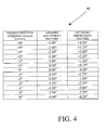
- the table of data can be generated, stored, and expressed in any desired format. For example, this table of data can be generated, stored, and expressed in a conventional spreadsheet format, such as shown in Fig. 4, which will be discussed in detail below.
- an adjustment control algorithm is selected.
- the adjustment control algorithm can be, generally speaking, any desired relationship that relates one or more operating conditions of the vehicle to one or more angular orientations of the headlight 11.
- a variety of such relationships are known in the art, and this invention is not intended to be limited to any particular relationship.
- Such relationships will be expressed in terms of a mathematical equation or similar relationship that can be readily processed using a microprocessor or similar electronic computing apparatus, such as the above-described headlight directional controller 14.
- the particular adjustment control algorithm that is selected may, if desired, vary from vehicle to vehicle in accordance with a variety of factors, including relative size and performance characteristics of the vehicle or any other desired condition.
- a plurality of operating conditions may be sensed by the condition sensors 15 and 16 and provided to the headlight directional controller 14 for use with the adjustment control mechanism.
- the condition sensors 15 and 16 may generate electrical signals to the headlight directional controller 14 that are representative of the road speed, the steering angle, and the pitch of the vehicle (which can, for example, be determined by sensing the front and rear suspension heights of the vehicle or by a pitch or level sensor).
- the time derivative of these operating conditions i.e., the rate of change of the road speed, steering angle, and pitch of the vehicle
- any other operating condition or conditions of the vehicle may be sensed and provided to the headlight directional controller 14.
- the table is generated using the adjustment control algorithm selected in the first step 31.
- the table can be generated in any desired manner. For example, let it be assumed that the selected adjustment control algorithm relates a single sensed operating condition to each of the angular adjustment control values for adjusting both the up/down orientation and the left/right orientation of the headlight 11.
- the table can be generated by initially selecting a first discrete sensed operating condition value that might be encountered during operation of the vehicle. Then, the selected adjustment control algorithm is solved using such first discrete sensed operating condition value to obtain the corresponding adjustment control values for the up/down and left/right orientation of the headlight 11. Then, the first discrete sensed operating condition value and the corresponding adjustment control values are stored in the table. This process can be repeated for any desired number of other discrete sensed operating condition values that might be encountered during operation of the vehicle.
- Fig. 4 is a representative example of a table, indicated generally at 40, that can be generated in accordance with the second step 32 of the table generating algorithm 30 illustrated in Fig. 3.
- a series of discrete sensed operating condition values is related to the angular adjustment control values (degrees of movement from the associated up/down and left/right reference positions or planes, for example) for adjusting both the up/down orientation and the left/right orientation of the headlight 11.
- a positive steering angle value represents steering toward left
- a negative steering angle value represents steering toward the right
- a positive up/down adjustment factor represents aiming the headlight 11 upwardly
- a negative up/down adjustment factor represents aiming the headlight 11 downwardly
- a positive left/right adjustment factor represents aiming the headlight 11 toward the left
- a negative left/right adjustment factor represents aiming the headlight 11 toward the right.
- a sensed steering angle of +6° results in an up/down adjustment factor of -3.00° and a left/right adjustment factor of +4.50°.
- a sensed steering angle of +5° results in an up/down adjustment factor of -2.50° and a left/right adjustment factor of +3.75°, and so on as shown in the table 40.
- the illustrated table 40 relates thirteen different sensed steering angle values to their corresponding adjustment control values for both the up/down and left/right orientation of the headlight 11.
- the table 40 can include a greater or lesser number of such sensed operating condition values, together with their corresponding adjustment control values.
- the illustrated table 40 relates only a single sensed operating condition value (steering angle) to the corresponding adjustment control values for both the up/down and left/right orientation of the headlight 11, the selected adjustment control algorithm may, as mentioned above, be responsive to a plurality of sensed operating condition values for determining the corresponding adjustment control values.
- a plurality of tables 40 can be generated, one for each of the plurality of sensed operating condition values. The size and extent of the table 40 or tables can be varied to accommodate any desired number of such sensed operating conditions.
- the table 40 generated in the second step 32 is stored in the memory of the headlight directional controller 14 illustrated in Fig. 1.
- the contents of the table 40 can be communicated serially to the headlight directional controller 14 by means of the input/output device 17 illustrated in Fig. 1 or in any other desired manner. Regardless of how it is communicated, the table 40 is preferably stored in a non-volatile memory of the headlight directional controller 14 for subsequent use in the manner described further below when the vehicle is operated.
- the generation of the table 40 and the storage of such table 40 in the memory of the headlight directional controller 14 allow a designer of the automatic directional control system 10 to quickly and easily alter the response characteristics of the system 10 as desired, without the need for direct access to the computer code or software that is used to operate the headlight directional controller 14. Rather, to effect such alterations, a designer can simply change some or all of the data points that are contained within the table 40. As will be described in detail below, the headlight directional controller 14 will use whatever data points that are contained within the table 40 in determining the need for adjustments in the angular orientation of the headlight 11.
- This structure also reduces the amount of processing power that is necessary for the headlight directional controller 14 because it can operate on a relatively simple look-up basis using the table 40, rather than having to calculate relatively high order equations that may be used to determine the data points contained within the table 40.
- Fig. 5 is a flow chart of an algorithm, indicated generally at 50, for operating the headlight directional controller illustrated in Fig. 1 to automatically implement directional angle adjustments in accordance with one or more of the sensed condition values from the condition sensors 15 and 16.
- a first step 51 of the operating algorithm 50 the values of one or more of the condition sensors 15 and 16 are read by the headlight directional controller 14.
- the operating algorithm 50 enters a decision point 52, wherein it is determined whether the value or values of the condition sensors 15 and 16 that have been read by the headlight directional controller 14 are specifically contained in the table 40. For example, using the table 40 illustrated in Fig.
- the operating algorithm 50 branches from the decision point 52 to an instruction 53, wherein the adjustment factors contained in the table 40 that correspond to the sensed condition value are looked up and stored in the headlight directional controller 14.
- the operating algorithm 50 next enters an instruction 54 wherein the value of the magnitude of the adjustment factor (i.e., the desired position for the headlight 11) is compared with the current position of the headlight 11.
- This step 54 of the operating algorithm 50 is optional and can be performed if one or more of the position feedback sensors 18 and 19 are provided in the automatic directional control system 10 to generate respective electrical signals that are representative of the actual up/down and left/right positions of the headlight 11, as described above.
- This step 54 of the operating algorithm 50 can be performed to determine how much of an adjustment is necessary to move the headlight 11 from its current position, as determined by the position feedback sensors 18 and 19, to the desired position, as defined by the adjustment factor obtained from the table 40.
- the value of the adjustment factor may, for example, be subtracted from the current position of the headlight 11 to determine the magnitude of the difference therebetween and, therefore, the magnitude of the adjustment that is necessary to move the headlight 11 from its current position to the desired position.
- this step 54 of the operating algorithm 50 can be accomplished in any other desired manner.
- the operating algorithm 50 enters a decision point 55, wherein it is determined whether the magnitude of the adjustment that is necessary to move the headlight 11 from its current position to the desired position is greater than a predetermined minimum threshold.
- This step in the operating algorithm 50 is also optional, but may be desirable to prevent the actuators 12 and 13 from being operated continuously or unduly frequently in response to relatively small variations in the sensed operating condition or conditions, such as relatively small bumps in the road. For example, if the current position of the headlight 11 is relatively close to the desired position, then it may be undesirable to effect any movement thereof.
- This step 55 will prevent the actuators 12 and 13 from being operated unless the current position of the headlight 11 is relatively far from the desired position.
- the headlight directional controller 14 may be programmed to be responsive only to changes in the suspension heights that occur at frequencies that are lower than the suspension rebound frequency of the vehicle (thereby ignoring relatively high frequency changes in suspension height that are likely the result of bumps in the road).
- relatively high frequency changes in the suspension heights could also be monitored to assist in deciphering relatively rough suspension changes from other suspension changes.
- the provision of the predetermined minimum threshold functions as a filter or dead band that minimizes or eliminates undesirable "hunting" of the actuators 12 and 13 for relatively small magnitudes of movement of the headlight 11. If the magnitude of the adjustment factor is not greater than the predetermined minimum threshold, then the operation of the actuators 12 and 13 is considered to be undesirable. Thus, the operating algorithm 50 branches from the decision point 55 back to the instruction 51, wherein the above-described steps of the operating algorithm 50 are repeated.
- the operating algorithm 50 branches from the decision point 55 to an instruction 56, wherein either or both of the actuators 12 and 13 are actuated to effect movement of the headlight 11.
- the headlight directional controller 14 uses the table 40 illustrated in Fig. 4, if the headlight directional controller 14 has read a steering angle value of -2°, then the headlight directional controller 14 will look up an up/down adjustment factor of -1.00° and a left/right adjustment factor of -1.50° from the table 40.
- the headlight directional controller 14 operates the actuators 12 and 13 to adjust the angular orientation of the headlight 11 to achieve the noted adjustment factors.
- the amounts of movement that are to be implemented by the two actuators 12 and 13 will be the same (i.e., the amount of up/down movement of the headlight 11 will be the same as the amount of left/right movement). More frequently, however, the amounts of movement that are to be implemented by the two actuators 12 and 13 will be different from one another. In the latter instances, it may be desirable to operate the two actuators 12 and 13 at two different speeds such that the overall movement of the headlight 11 is relatively uniform.
- the up/down actuator 12 For example, if the amount of movement that is to be implemented by the up/down actuator 12 is twice as large as the amount of movement that is to be implemented by the left/right actuator 13, then it may be desirable to operate the up/down actuator 12 at one-half of the speed of the left/right actuator 13 so that the movements of both actuators 12 and 13 (and, therefore, the overall movement of the headlight 11) will start and stop at approximately the same time.
- the vehicle is provided with two different headlights 11, as is commonly found, then it may be desirable to control the respective movements of such different headlights 11 in such a manner that they both start and stop at approximately the same time. This can be accomplished, for example, by providing a single headlight directional controller 14 for not only controlling, but also coordinating the movements of both of the headlights 11 in response to the sensed operating conditions.
- Such operations can be performed in an open loop manner if desired, wherein the actuators 12 and 13 are operated to achieve predetermined amounts of movement.
- the actuators 12 and 13 can be embodied as step motors that are operated a predetermined number of steps to achieve predetermined amounts of movement.
- the actuators 12 and 13 can be operated for predetermined periods of time to achieve the predetermined amounts of movement.
- the operations of the actuators 12 and 13 are performed in a closed loop manner. To accomplish this, the actuators 12 and 13 are operated until either or both of the position feedback sensors 18 and 19 generate signals indicate that the headlight 11 has actually achieved the predetermined amounts of movement or desired position. In either event, the operating algorithm 50 then branches back to the instruction 51, wherein the above-described steps of the algorithm 50 are repeated.
- the operating algorithm 50 branches from the decision point 52 to an instruction 57, wherein the adjustment factors that are specifically contained in the table 40 that correspond to the adjacent sensed condition values are looked up and stored in the headlight directional controller 14. For example, using the table 40 illustrated in Fig. 4, if the headlight directional controller 14 has read a steering angle value of -1.5°, then it is determined that the value of the condition sensor 15 is not specifically contained within the table 40.
- the two adjustment factors specifically contained in the table 40 that are adjacent to the sensed condition value are looked up and stored in the headlight directional controller 14.
- the operating algorithm 50 next enters an instruction 58, wherein the actual adjustment factors to be implemented by the headlight directional controller 14 are interpolated or otherwise calculated from the stored adjustment factors that are adjacent to the sensed condition value. For example, as mentioned above, if the actual sensed steering angle value is -1.5°, then the headlight directional controller 14 looks up the adjustment factors for the steering angle values of -1° and -2°. The up/down adjustment factor for a steering angle value of -1° is -0.50 while the up/down adjustment factor for a steering angle value of -2° is -1.00°. If the calculation that is performed by the headlight directional controller 14 is a simple arithmetic mean, then the interpolated up/down adjustment factor would be -0.75°.
- the left/right adjustment factor for a steering angle value of -1° is -0.75°
- the left/right adjustment factor for a steering angle value of -2° is -1.50°. If the calculation that is performed by the headlight directional controller 14 is a simple arithmetic mean, then the interpolated left/right adjustment factor would be -1.13°. Thereafter, the operating algorithm 50 branches to the decision point 55, and the remainder of the operating algorithm 50 is performed as described above.
- the interpolation that is performed by the headlight directional controller 14 can be accomplished in any desired manner.
- the performance of the simple arithmetic mean described above is intended to be representative of any mathematical or other function that can be performed to calculate, derive, or otherwise obtain adjustment factors that are not present in the table 40.
- this interpolation has been described in the context of using only the two condition values that are directly adjacent to the actual sensed condition value, it will be appreciated that the adjustment values for any single condition value or combination of sensed condition values may be selected for the interpolation. For example, several of the condition values both above and below the sensed condition value can be read from the table 40 to derive a trend line or other good estimate of the adjustment factors that are not present in the table 40. Performance of this interpolation does not require any significant increase in the amount of processing power that is necessary for the headlight directional controller 14.
- a single table 40 that provides adjustment values based upon a single sensed operating condition (steering angle of the vehicle, in the illustrated embodiment).
- this invention may be practiced by sensing a plurality of operating conditions of the vehicle. For example, let it be assumed that both steering angle and vehicle road speed are sensed by the condition sensors 15 and 16.
- the adjustment control algorithm that is selected in the first step 31 of the table generating algorithm 30 can be designed to accommodate multiple sensed conditions.
- a first table (such as the table 40 illustrated in Fig. 4) may be generated that relates the steering angle of the vehicle to the angular adjustment control values for adjusting both the up/down orientation and the left/right orientation of the headlight 11.
- a second, similar table may also be generated that relates the road speed of the vehicle to the angular adjustment control values for adjusting both the up/down orientation and the left/right orientation of the headlight 11.
- the first and second tables may provide differing angular adjustment control values.
- the interpolation step 57 of the operating algorithm 50 can be performed to interpolate a single composite adjustment value that is based upon the two different values provided in the first and second tables for the pair of sensed operating conditions. This interpolation can be performed in the same manner as described above for each of the actuators 12 and 13.
- a variety of control strategies can be implemented using the automatic directional control system 10 described above.
- the pitch of the vehicle can change as a result of a variety of factors, including acceleration, deceleration, and weight distribution of the vehicle. These pitch variations can alter the angle at which the beam of light projects from the headlight 11 in the up and down direction relative to a horizontal reference position or plane.
- the automatic directional control system 10 can be responsive to such pitch variations for operating the up/down actuator 12 to maintain the angle at which the beam of light projects from the headlight 11 in the up and down direction relatively constant to the horizontal reference position or plane.
- the angle at which the beam of light projects from the headlight 11 in the left and right direction relative to a vertical reference position or plane can be adjusted in accordance with the sensed steering angle.
- the angle at which the beam of light projects from the headlight 11 in the up and down direction relative to a horizontal reference position or plane can also be adjusted in accordance with the sensed steering angle. This can be done to lower the headlight beams as the vehicle is turning a corner. The advantages of this are not only to better illuminate the road surface in the path of movement of the vehicle, but also to reduce headlight glare to other vehicles as the turn is negotiated.
- the automatic directional control system 10 of this invention can be responsive to one or more operating conditions of the vehicle to automatically activate these other lights on the vehicle.
- the automatic directional control system 10 of this invention can be responsive to a steering angle in excess of a predetermined magnitude for automatically activating these other lights on the vehicle. This can be effective to extend the angular range of illumination of the road surface.
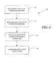
- Fig. 6 is a flow chart of an algorithm, indicated generally at 60, for operating the headlight directional controller illustrated in Fig. 1 to automatically implement directional angle adjustments in accordance with the rate of change of one or more of the sensed condition values.
- the headlight directional controller 14 can be operated to automatically implement directional angle adjustments in accordance with one or more of the sensed condition values or in accordance with the rate of change of one or more of the sensed condition values.
- the algorithm 60 has a first step 61 wherein the values of one or more of the condition sensors 15 and 16 are initially read by the headlight directional controller 14. Then, the algorithm 60 enters a second step 62 wherein the values of one or more of the condition sensors 15 and 16 are subsequently read a second time by the headlight directional controller 14. The second reading of the condition sensors 15 and 16 occurs a predetermined amount of time after the first reading thereof. Next, the algorithm enters a third step 63 wherein a rate of change of the sensed condition or conditions is calculated. The rate of change of the sensed condition can be calculated as the difference between the first and second readings divided by the amount of time therebetween or by any other desired means.
- the sensed condition is vehicle speed
- the difference between the first sensed vehicle speed and the second sensed vehicle speed, divided by the amount of time therebetween, would yield a number that is representative of the acceleration of the vehicle.
- either or both of the actuators 12 and 13 are actuated to effect movement of the headlight 11 in accordance with the calculated rate of change of the sensed condition.
- Such movement of the headlight 11 can be effected in a manner that is similar to that described above.
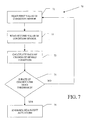
- Fig. 7 is a flow chart of an algorithm, indicated generally at 70, for operating the headlight directional controller illustrated in Fig. 1 to automatically implement directional angle adjustments, but only when the rate of change of one or more of the sensed condition values is less than (or greater than) a predetermined value.
- the headlight directional controller 14 can be operated to automatically implement directional angle adjustments in accordance with one or more of the sensed condition values.
- the headlight directional controller 14 automatically implements directional angle adjustments in response to the sensed condition values (or in response to the rate of change of the sensed condition values), but only when the rate of change of one or more of the sensed condition values is less than (or greater than) a predetermined value.
- the algorithm 70 has a first step 71 wherein the values of one or more of the condition sensors 15 and 16 are initially read by the headlight directional controller 14. Then, the algorithm 70 enters a second step 72 wherein the values of one or more of the condition sensors 15 and 16 are subsequently read a second time by the headlight directional controller 14. The second reading of the condition sensors 15 and 16 occurs a predetermined amount of time after the first reading thereof. Next, the algorithm enters a third step 73 wherein a rate of change of the sensed condition or conditions is calculated. The rate of change of the sensed condition can be calculated as the difference between the first and second readings divided by the amount of time therebetween or by any other desired means. For example, if the sensed condition is suspension height, then the difference between the first sensed suspension height and the second sensed suspension height, divided by the amount of time therebetween, would yield a number that is representative of the rate of change of the suspension height of the vehicle.
- This threshold sensing algorithm 70 can function to prevent the headlight directional controller 14 from being operated to automatically implement directional angle adjustments when the rate of change of the suspension height of the vehicle changes more rapidly than the system can effect corrective changes. For example, if the vehicle is operated on a bumpy road, the algorithm 70 will prevent the headlight directional controller 14 from attempting to correct for every single bump that is encountered. However, for relatively low frequency or rates of change in the suspension height of the vehicle, such as can occur when accelerating, decelerating, and weight changes, the headlight directional controller 14 will be operated in the normal manner to effect corrective actions, as described above.
- the input/output device 17 is connected to (or can be connected to) the headlight directional controller 14 for facilitating communication therewith, and the input/output device 17 can be used for calibrating the automatic directional control system illustrated in Fig. 1 so as to define an initial reference position or positions for the headlight 11 from which the headlight directional controller 14 can implement directional angle adjustments. Additionally, however, the input/output device 17 can be employed as a diagnostic tool. To accomplish this, the input/output device 17 can be embodied as a conventional microprocessor or similar electronically programmable device that can be connected to the headlight directional controller 14 to read fault codes that may be generated during the operation thereof.
- the headlight directional controller 14 can be programmed to generate fault codes whenever a fault condition or other anomaly occurs or is detected. Such fault codes can be stored in the headlight directional controller 14 until the input/output device 17 is subsequently connected thereto. When so connected, the input/output device 17 can read such codes and display them for an operator. As a result, the operator can take whatever corrective actions are necessary to address the fault condition or anomaly.
- the input/output device 17 can also be programmed to clear the fault codes from the headlight directional controller 14 after they are read.
Landscapes
- Engineering & Computer Science (AREA)
- Mechanical Engineering (AREA)
- Chemical & Material Sciences (AREA)
- Analytical Chemistry (AREA)
- Physics & Mathematics (AREA)
- General Physics & Mathematics (AREA)
- Lighting Device Outwards From Vehicle And Optical Signal (AREA)
Abstract
Description
- This invention relates in general to headlights that are provided on vehicles for illuminating dark road surfaces or other areas in the path of movement. In particular, this invention relates to an automatic directional control system for such vehicle headlights.
- Virtually all land vehicles, and many other types of vehicles (such as boats and airplanes, for example), are provided with one or more headlights that are adapted to illuminate a portion of a dark road surface or other area in the path of movement of the vehicle to facilitate safe travel thereon. Typically, each headlight is mounted on or near the front end of the vehicle and is oriented in such a manner that a beam of light is projected forwardly therefrom. The angle at which the beam of light projects from the headlight can, for example, be characterized in a variety of ways, including (1) up and down relative to a horizontal reference position or plane and (2) left and right relative to a vertical reference position or plane. Such directional aiming angles are usually set at the time of assembly of the headlight into the vehicle so as to illuminate a predetermined portion of the road surface or other area in the path of movement of the vehicle.
- In the past, these headlights have been mounted on the vehicle in fixed positions relative thereto such that the beams of light are projected therefrom at predetermined directional aiming angles relative to the vehicle. Although such fixed aiming angle headlight systems have and continue to function adequately, they cannot alter the directional aiming angles of the headlights to account for changes in the operating conditions of the vehicle. For example, if the speed of the vehicle is increased, it would be desirable to adjust the aiming angle of the headlights upwardly such that an area that is somewhat farther in front of the vehicle is more brightly illuminated. On the other hand, if the speed of the vehicle is decreased, it would be desirable to adjust the aiming angle of the headlights downwardly such that an area that is somewhat closer in front of the vehicle is more brightly illuminated. Similarly, if the vehicle turns a comer, it would be desirable to adjust the aiming angle of the headlights either toward the left or toward the right (depending on the direction of the turn) such that an area that is somewhat lateral to the front of the vehicle is more brightly illuminated.
- To accomplish this, it is known to provide a directional control system for vehicle headlights that is capable of automatically altering the directional aiming angles of the headlights to account for changes in the operating conditions of the vehicle. A variety of such automatic directional control systems for vehicle headlights are known in the art. However, such known automatic headlight directional control systems have been found to be deficient for various reasons. Thus, it would be desirable to provide an improved structure for an automatic headlight directional control system that addresses such deficiencies.
- This invention relates to an improved structure and method for operating a directional control system for vehicle headlights that is capable of automatically altering the directional aiming angles of the headlights to account for changes in the operating conditions of the vehicle. One or more operating condition sensors may be provided that generate signals that are representative of an operating condition of the vehicle, such as road speed, steering angle, pitch, suspension height, rate of change of road speed, rate of change of steering angle, rate of change of pitch, and rate of change of suspension height of the vehicle. A controller is responsive to the sensor signal for generating an output signal. An actuator is adapted to be connected to the headlight to effect movement thereof in accordance with the output signal. The controller can include a table that relates values of sensed operating condition to values of the output signal. The controller is responsive to the sensor signal for looking up the output signal in the table.
- Various objects and advantages of this invention will become apparent to those skilled in the art from the following detailed description of the preferred embodiments, when read in light of the accompanying drawings.
-
- Fig. 1 is a block diagram of an automatic directional control system for a vehicle headlight in accordance with this invention.
- Fig. 2 is a flow chart of an algorithm for calibrating the automatic directional control system illustrated in Fig. 1 so as to define an initial reference position for the headlight from which the headlight directional controller can implement directional angle adjustments.
- Fig. 3 is a flow chart of an algorithm for generating a table that relates one or more sensed vehicle operating condition values to one or more headlight directional angle adjustment factors and for storing such table in the headlight directional controller illustrated in Fig. 1.
- Fig. 4 is an example of a table that can be generated and stored in the headlight directional controller in accordance with the table generating algorithm illustrated in Fig. 3.
- Fig. 5 is a flow chart of an algorithm for operating the headlight directional controller illustrated in Fig. 1 to automatically implement directional angle adjustments in accordance with sensed condition values.
- Fig. 6 is a flow chart of an algorithm for operating the headlight directional controller illustrated in Fig. 1 to automatically implement directional angle adjustments in accordance with the rate of change of one or more of the sensed condition values.
- Fig. 7 is a flow chart of an algorithm for operating the headlight directional controller illustrated in Fig. 1 to automatically implement directional angle adjustments, but only when the rate of change of one or more of the sensed condition values is less than (or greater than) a predetermined value.
-
- Referring now to the drawings, there is illustrated in Fig. 1 an automatic directional control system, indicated generally at 10, for a
vehicle headlight 11 in accordance with this invention. The illustratedheadlight 11 is, of itself, conventional in the art and is intended to be representative of any device that can be supported on any type of vehicle for the purpose of illuminating any area, such as an area in the path of movement of the vehicle. Theheadlight 11 is typically mounted on or near the front end of a vehicle (not shown) and is oriented in such a manner that a beam of light is projected therefrom. In a manner that is well known in the art, theheadlight 11 is adapted to illuminate a portion of a dark road surface or other area in the path of movement of the vehicle to facilitate safe travel thereon. - The
headlight 11 is adjustably mounted on the vehicle such that the directional orientation at which the beam of light projects therefrom can be adjusted relative to the vehicle. Any desired mounting structure can be provided to accomplish this. Typically, theheadlight 11 is mounted on the vehicle such that the angle at which the beam of light projects therefrom can be adjusted both (1) up and down relative to a horizontal reference position or plane and (2) left and right relative to a vertical reference position or plane. Although this invention will be described and illustrated in the context of a headlight that is adjustable in both the up/down direction and the left/right direction, it will be appreciated that this invention may be practiced with anyheadlight 11 that is adjustable in any single direction or multiple directions of movement, whether up/down, left/right, or any other direction. - To effect movement of the illustrated
headlight 11 relative to the vehicle, an up/down actuator 12 and a left/right actuator 13 are provided. Theactuators actuators headlights 11. In the illustrated embodiment, the up/down actuator 12 is mechanically connected to theheadlight 11 such that theheadlight 11 can be selectively adjusted up and down relative to a horizontal reference position or plane. Similarly, the illustrated left/right actuator 13 is mechanically connected to theheadlight 11 such that theheadlight 11 can be selectively adjusted left and right relative to a vertical reference position or plane. - A headlight
directional controller 14 is provided for controlling the operations of the up/downactuator 12 and the left/right actuator 13 and, therefore, the angle at which the beam of light projects from theheadlight 11 relative to the vehicle. The headlightdirectional controller 14 can be embodied as any control system, such as a microprocessor or programmable electronic controller, that is responsive to one or more sensed operating conditions of the vehicle for selectively operating the up/downactuator 12 and the left/right actuator 13. To accomplish this, the automaticdirectional control system 10 can include, for example, a pair ofcondition sensors directional controller 14. Thecondition sensors directional controller 14. However, if desired, only a single one of thecondition sensors output device 17 is connected to (or can be connected to) the headlightdirectional controller 14 for facilitating communication therewith in the manner described below. - If desired, a first
position feedback sensor 18 may be provided for the up/down actuator 12, and a secondposition feedback sensor 19 may be provided for the left/right actuator 13. Theposition feedback sensors headlight 11. Thus, the firstposition feedback sensor 18 is responsive to the actual up/down position of the headlight 11 (as determined by a portion of the up/down actuator 12, for example) for generating an electrical signal to the headlightdirectional controller 14 that is representative thereof. Similarly, the secondposition feedback sensor 19 is responsive to the actual left/right position of the headlight 11 (as determined by a portion of the left/right actuator 13, for example) for generating an electrical signal to the headlightdirectional controller 14 that is representative thereof. Theposition feedback sensors respective actuators - Alternatively, the
position feedback sensors headlight 11 has achieved respective predetermined up/down or left/right positions. This can be accomplished, for example, using a conventional optical interrupter (not shown) for each of theactuators headlight 11 for movement therewith. Each of the optical interrupters further includes an optical source and sensor assembly. As theheadlight 11 is moved by theactuators directional controller 14. Conversely, when the flag is in the second position relative to the optical source and sensor assembly, the sensor is not permitted to receive light emitted from the source. As a result, a second signal is generated from the optical source and sensor assembly to the headlightdirectional controller 14. Thus, the edge of the flag defines a transition between the first and second positions of the flag relative to the optical source and sensor assembly and, therefore, defines a predetermined up/down or left/right position of theheadlight 11. The nature of the signal generated from the optical source and sensor assembly to the headlight directional controller 14 (i.e., the first signal or the second signal) can also be used to determine on which side of the predetermined position (the left side or the right side, for example) that theheadlight 11 is positioned. The purpose for suchposition feedback sensors - Fig. 2 is a flow chart of an algorithm, indicated generally at 20, for calibrating the automatic directional control system illustrated in Fig. 1 so as to define an initial reference position or positions for the
headlight 11 from which the headlightdirectional controller 14 can implement directional angle adjustments. As mentioned above, theheadlight 11 is mounted on the vehicle such that the angle at which the beam of light projects therefrom can be adjusted both up and down relative to a horizontal reference position or plane and left and right relative to a vertical reference position or plane. To insure accurate positioning of theheadlight 11, it is desirable that a reference position or positions be initially established by the headlightdirectional controller 14. Subsequent directional angle adjustments can be made by the headlightdirectional controller 14 from the pre-established reference position or positions established by thiscalibration algorithm 20. - To accomplish this, the
calibration algorithm 20 has afirst step 21 wherein the headlightdirectional controller 14 is caused to enter a calibration mode of operation. In the calibration mode of operation, the headlightdirectional controller 14 is responsive to input signals from the input/output device 17 (or from another source, if desired) for causing manual operation of the up/downactuator 12 and the left/right actuator 13. Thus, while the headlightdirectional controller 14 is in the calibration mode of operation, an operator of the input/output device 17 can manually effect either up/down movement of theheadlight 11, left/right movement of theheadlight 11, or both, as desired. - In a second step 22 of the
calibration algorithm 20, the up/downactuator 12 and the left/right actuator 13 are manually operated to aim theheadlight 11 in a predetermined reference orientation. This can be accomplished by use of the input/output device 17 that, as mentioned above, is connected to (or can be connected to) the headlightdirectional controller 14. Traditionally, the aiming of aheadlight 11 has been accomplished by parking the vehicle on a surface near a wall or other vertical structure, providing a reference target at a predetermined location on the wall or other structure, and mechanically adjusting the mounting structure of theheadlight 11 such that the center of the beam therefrom is projected at the reference target. In this invention, the vehicle is parked on a surface near a wall or other vertical structure, and a reference target is provided at a predetermined location on the wall or other structure, as described above. Next, in accordance with the second step 22 of thiscalibration algorithm 20, the input/output device 17 is operated to generate electrical signals to the headlightdirectional controller 14. In response to such electrical signals, the headlightdirectional controller 14 operates the up/downactuator 12 and the left/right actuator 13 to move theheadlight 11 such that center of the beam projecting therefrom is aimed at the reference target. When the beam from theheadlight 11 is so aimed, then theheadlight 11 is determined to be oriented in the initial reference position from which the headlightdirectional controller 14 can subsequently implement directional angle adjustments. - In a
third step 23 of thecalibration algorithm 20, once this initial reference position for theheadlight 11 has been achieved, such position is stored in the headlightdirectional controller 14 as the predetermined initial reference position. This can be accomplished by means of theposition feedback sensors position feedback sensors headlight 11 or of the predetermined positions for the headlight. Thus, the firstposition feedback sensor 18 is responsive to the actual up/down position of the headlight 11 (as determined by the up/downactuator 12, for example) for generating an electrical signal to the headlightdirectional controller 14 that is representative thereof. Similarly, the secondposition feedback sensor 19 is responsive to the actual left/right position of the headlight 11 (as determined by the left/right actuator 13, for example) for generating an electrical signal to the headlightdirectional controller 14 that is representative thereof. Accordingly, thethird step 23 of thecalibration algorithm 20 can be performed by causing the headlightdirectional controller 14 to read the signals from theposition feedback sensors headlight 11 as the initial reference positions from which the headlightdirectional controller 14 can subsequently implement directional angle adjustments. - The current position of the
headlight 11 is preferably stored in the non-volatile memory of the headlightdirectional controller 14 for reference during normal operation of the automaticdirectional control system 10 described below. Thus, when the automaticdirectional control system 10 is initially activated (such as when the electrical system of the vehicle is initially turned on), the headlightdirectional controller 14 can position theheadlight 11 at or near the calibrated position utilizing the signals comparing the current position of the headlight 11 (as determined by the signals generated by theposition feedback sensors 18 and 19) with the predetermined reference position determined by thecalibration algorithm 20. - Fig. 3 is a flow chart of an algorithm, indicated generally at 30, for generating a table that relates the sensed condition values from the
condition sensors directional controller 14, and further for storing such table in the headlightdirectional controller 14 illustrated in Fig. 1. As used herein, the term "table" is intended to be representative of any collection or association of data that relates one or more of the sensed condition values to one or more of the headlight directional angle adjustment factors. The table of data can be generated, stored, and expressed in any desired format. For example, this table of data can be generated, stored, and expressed in a conventional spreadsheet format, such as shown in Fig. 4, which will be discussed in detail below. - In a
first step 31 of thetable generating algorithm 30, an adjustment control algorithm is selected. The adjustment control algorithm can be, generally speaking, any desired relationship that relates one or more operating conditions of the vehicle to one or more angular orientations of theheadlight 11. A variety of such relationships are known in the art, and this invention is not intended to be limited to any particular relationship. Typically, such relationships will be expressed in terms of a mathematical equation or similar relationship that can be readily processed using a microprocessor or similar electronic computing apparatus, such as the above-described headlightdirectional controller 14. The particular adjustment control algorithm that is selected may, if desired, vary from vehicle to vehicle in accordance with a variety of factors, including relative size and performance characteristics of the vehicle or any other desired condition. - As mentioned above, a plurality of operating conditions may be sensed by the
condition sensors directional controller 14 for use with the adjustment control mechanism. For example, thecondition sensors directional controller 14 that are representative of the road speed, the steering angle, and the pitch of the vehicle (which can, for example, be determined by sensing the front and rear suspension heights of the vehicle or by a pitch or level sensor). Additionally, the time derivative of these operating conditions (i.e., the rate of change of the road speed, steering angle, and pitch of the vehicle) can be sensed or calculated. However, any other operating condition or conditions of the vehicle may be sensed and provided to the headlightdirectional controller 14. - In a
second step 32 of thetable generating algorithm 30, the table is generated using the adjustment control algorithm selected in thefirst step 31. The table can be generated in any desired manner. For example, let it be assumed that the selected adjustment control algorithm relates a single sensed operating condition to each of the angular adjustment control values for adjusting both the up/down orientation and the left/right orientation of theheadlight 11. The table can be generated by initially selecting a first discrete sensed operating condition value that might be encountered during operation of the vehicle. Then, the selected adjustment control algorithm is solved using such first discrete sensed operating condition value to obtain the corresponding adjustment control values for the up/down and left/right orientation of theheadlight 11. Then, the first discrete sensed operating condition value and the corresponding adjustment control values are stored in the table. This process can be repeated for any desired number of other discrete sensed operating condition values that might be encountered during operation of the vehicle. - As mentioned above, Fig. 4 is a representative example of a table, indicated generally at 40, that can be generated in accordance with the
second step 32 of thetable generating algorithm 30 illustrated in Fig. 3. As shown therein, a series of discrete sensed operating condition values (degrees of steering angles, for example) is related to the angular adjustment control values (degrees of movement from the associated up/down and left/right reference positions or planes, for example) for adjusting both the up/down orientation and the left/right orientation of theheadlight 11. For the purposes of illustration only, let it be assumed that (1) a positive steering angle value represents steering toward left, while a negative steering angle value represents steering toward the right, (2) a positive up/down adjustment factor represents aiming theheadlight 11 upwardly, while a negative up/down adjustment factor represents aiming theheadlight 11 downwardly, and (3) a positive left/right adjustment factor represents aiming theheadlight 11 toward the left, while a negative left/right adjustment factor represents aiming theheadlight 11 toward the right. - Thus, in accordance with the selected adjustment control algorithm, a sensed steering angle of +6° results in an up/down adjustment factor of -3.00° and a left/right adjustment factor of +4.50°. Similarly, a sensed steering angle of +5° results in an up/down adjustment factor of -2.50° and a left/right adjustment factor of +3.75°, and so on as shown in the table 40. The illustrated table 40 relates thirteen different sensed steering angle values to their corresponding adjustment control values for both the up/down and left/right orientation of the
headlight 11. However, the table 40 can include a greater or lesser number of such sensed operating condition values, together with their corresponding adjustment control values. Furthermore, although the illustrated table 40 relates only a single sensed operating condition value (steering angle) to the corresponding adjustment control values for both the up/down and left/right orientation of theheadlight 11, the selected adjustment control algorithm may, as mentioned above, be responsive to a plurality of sensed operating condition values for determining the corresponding adjustment control values. Alternatively, as will be discussed further below, a plurality of tables 40 can be generated, one for each of the plurality of sensed operating condition values. The size and extent of the table 40 or tables can be varied to accommodate any desired number of such sensed operating conditions. - Referring back to Fig. 3, in a
third step 33 of thetable generating algorithm 30, the table 40 generated in thesecond step 32 is stored in the memory of the headlightdirectional controller 14 illustrated in Fig. 1. The contents of the table 40 can be communicated serially to the headlightdirectional controller 14 by means of the input/output device 17 illustrated in Fig. 1 or in any other desired manner. Regardless of how it is communicated, the table 40 is preferably stored in a non-volatile memory of the headlightdirectional controller 14 for subsequent use in the manner described further below when the vehicle is operated. - As mentioned above, it may be desirable to vary the algorithm that is selected for use in implementing the headlight directional angle adjustment factors. The generation of the table 40 and the storage of such table 40 in the memory of the headlight
directional controller 14 allow a designer of the automaticdirectional control system 10 to quickly and easily alter the response characteristics of thesystem 10 as desired, without the need for direct access to the computer code or software that is used to operate the headlightdirectional controller 14. Rather, to effect such alterations, a designer can simply change some or all of the data points that are contained within the table 40. As will be described in detail below, the headlightdirectional controller 14 will use whatever data points that are contained within the table 40 in determining the need for adjustments in the angular orientation of theheadlight 11. This structure also reduces the amount of processing power that is necessary for the headlightdirectional controller 14 because it can operate on a relatively simple look-up basis using the table 40, rather than having to calculate relatively high order equations that may be used to determine the data points contained within the table 40. - Fig. 5 is a flow chart of an algorithm, indicated generally at 50, for operating the headlight directional controller illustrated in Fig. 1 to automatically implement directional angle adjustments in accordance with one or more of the sensed condition values from the
condition sensors first step 51 of the operatingalgorithm 50, the values of one or more of thecondition sensors directional controller 14. Then, the operatingalgorithm 50 enters adecision point 52, wherein it is determined whether the value or values of thecondition sensors directional controller 14 are specifically contained in the table 40. For example, using the table 40 illustrated in Fig. 4, if the headlightdirectional controller 14 has read a steering angle value of -2°, then it is determined that the value of thecondition sensor 15 is specifically contained within the table 40. In this instance, the operatingalgorithm 50 branches from thedecision point 52 to aninstruction 53, wherein the adjustment factors contained in the table 40 that correspond to the sensed condition value are looked up and stored in the headlightdirectional controller 14. - The operating
algorithm 50 next enters aninstruction 54 wherein the value of the magnitude of the adjustment factor (i.e., the desired position for the headlight 11) is compared with the current position of theheadlight 11. Thisstep 54 of the operatingalgorithm 50 is optional and can be performed if one or more of theposition feedback sensors directional control system 10 to generate respective electrical signals that are representative of the actual up/down and left/right positions of theheadlight 11, as described above. Thisstep 54 of the operatingalgorithm 50 can be performed to determine how much of an adjustment is necessary to move theheadlight 11 from its current position, as determined by theposition feedback sensors headlight 11 to determine the magnitude of the difference therebetween and, therefore, the magnitude of the adjustment that is necessary to move theheadlight 11 from its current position to the desired position. However, thisstep 54 of the operatingalgorithm 50 can be accomplished in any other desired manner. - Next, the operating
algorithm 50 enters adecision point 55, wherein it is determined whether the magnitude of the adjustment that is necessary to move theheadlight 11 from its current position to the desired position is greater than a predetermined minimum threshold. This step in the operatingalgorithm 50 is also optional, but may be desirable to prevent theactuators headlight 11 is relatively close to the desired position, then it may be undesirable to effect any movement thereof. Thisstep 55 will prevent theactuators headlight 11 is relatively far from the desired position. As another example, if thecondition sensors directional controller 14 may be programmed to be responsive only to changes in the suspension heights that occur at frequencies that are lower than the suspension rebound frequency of the vehicle (thereby ignoring relatively high frequency changes in suspension height that are likely the result of bumps in the road). However, relatively high frequency changes in the suspension heights could also be monitored to assist in deciphering relatively rough suspension changes from other suspension changes. - In any event, the provision of the predetermined minimum threshold functions as a filter or dead band that minimizes or eliminates undesirable "hunting" of the
actuators headlight 11. If the magnitude of the adjustment factor is not greater than the predetermined minimum threshold, then the operation of theactuators algorithm 50 branches from thedecision point 55 back to theinstruction 51, wherein the above-described steps of the operatingalgorithm 50 are repeated. - If, on the other hand, the magnitude of the adjustment factor is greater than the predetermined minimum threshold, then the operation of the
actuators algorithm 50 branches from thedecision point 55 to aninstruction 56, wherein either or both of theactuators headlight 11. For example, using the table 40 illustrated in Fig. 4, if the headlightdirectional controller 14 has read a steering angle value of -2°, then the headlightdirectional controller 14 will look up an up/down adjustment factor of -1.00° and a left/right adjustment factor of -1.50° from the table 40. The headlightdirectional controller 14 operates theactuators headlight 11 to achieve the noted adjustment factors. - In some instances, the amounts of movement that are to be implemented by the two
actuators headlight 11 will be the same as the amount of left/right movement). More frequently, however, the amounts of movement that are to be implemented by the twoactuators actuators headlight 11 is relatively uniform. For example, if the amount of movement that is to be implemented by the up/downactuator 12 is twice as large as the amount of movement that is to be implemented by the left/right actuator 13, then it may be desirable to operate the up/downactuator 12 at one-half of the speed of the left/right actuator 13 so that the movements of bothactuators 12 and 13 (and, therefore, the overall movement of the headlight 11) will start and stop at approximately the same time. Similarly, if the vehicle is provided with twodifferent headlights 11, as is commonly found, then it may be desirable to control the respective movements of suchdifferent headlights 11 in such a manner that they both start and stop at approximately the same time. This can be accomplished, for example, by providing a single headlightdirectional controller 14 for not only controlling, but also coordinating the movements of both of theheadlights 11 in response to the sensed operating conditions. - Such operations can be performed in an open loop manner if desired, wherein the
actuators actuators actuators actuators actuators position feedback sensors headlight 11 has actually achieved the predetermined amounts of movement or desired position. In either event, the operatingalgorithm 50 then branches back to theinstruction 51, wherein the above-described steps of thealgorithm 50 are repeated. - Referring back to the
decision point 52, if the value or values of thecondition sensors directional controller 14 are not specifically contained in the table 40, then the operatingalgorithm 50 branches from thedecision point 52 to aninstruction 57, wherein the adjustment factors that are specifically contained in the table 40 that correspond to the adjacent sensed condition values are looked up and stored in the headlightdirectional controller 14. For example, using the table 40 illustrated in Fig. 4, if the headlightdirectional controller 14 has read a steering angle value of -1.5°, then it is determined that the value of thecondition sensor 15 is not specifically contained within the table 40. Rather than simply default to the closest value that is contained within the table 40, the two adjustment factors specifically contained in the table 40 that are adjacent to the sensed condition value (namely, the adjustment factors for the steering angle values of -1° and -2°) are looked up and stored in the headlightdirectional controller 14. - The operating
algorithm 50 next enters aninstruction 58, wherein the actual adjustment factors to be implemented by the headlightdirectional controller 14 are interpolated or otherwise calculated from the stored adjustment factors that are adjacent to the sensed condition value. For example, as mentioned above, if the actual sensed steering angle value is -1.5°, then the headlightdirectional controller 14 looks up the adjustment factors for the steering angle values of -1° and -2°. The up/down adjustment factor for a steering angle value of -1° is -0.50 while the up/down adjustment factor for a steering angle value of -2° is -1.00°. If the calculation that is performed by the headlightdirectional controller 14 is a simple arithmetic mean, then the interpolated up/down adjustment factor would be -0.75°. Similarly, the left/right adjustment factor for a steering angle value of -1° is -0.75°, while the left/right adjustment factor for a steering angle value of -2° is -1.50°. If the calculation that is performed by the headlightdirectional controller 14 is a simple arithmetic mean, then the interpolated left/right adjustment factor would be -1.13°. Thereafter, the operatingalgorithm 50 branches to thedecision point 55, and the remainder of the operatingalgorithm 50 is performed as described above. - The interpolation that is performed by the headlight
directional controller 14 can be accomplished in any desired manner. The performance of the simple arithmetic mean described above is intended to be representative of any mathematical or other function that can be performed to calculate, derive, or otherwise obtain adjustment factors that are not present in the table 40. Furthermore, although this interpolation has been described in the context of using only the two condition values that are directly adjacent to the actual sensed condition value, it will be appreciated that the adjustment values for any single condition value or combination of sensed condition values may be selected for the interpolation. For example, several of the condition values both above and below the sensed condition value can be read from the table 40 to derive a trend line or other good estimate of the adjustment factors that are not present in the table 40. Performance of this interpolation does not require any significant increase in the amount of processing power that is necessary for the headlightdirectional controller 14. - The above discussion has assumed the use of a single table 40 that provides adjustment values based upon a single sensed operating condition (steering angle of the vehicle, in the illustrated embodiment). However, as discussed above, this invention may be practiced by sensing a plurality of operating conditions of the vehicle. For example, let it be assumed that both steering angle and vehicle road speed are sensed by the
condition sensors first step 31 of thetable generating algorithm 30 can be designed to accommodate multiple sensed conditions. Alternatively, however, a first table (such as the table 40 illustrated in Fig. 4) may be generated that relates the steering angle of the vehicle to the angular adjustment control values for adjusting both the up/down orientation and the left/right orientation of theheadlight 11. A second, similar table (not shown) may also be generated that relates the road speed of the vehicle to the angular adjustment control values for adjusting both the up/down orientation and the left/right orientation of theheadlight 11. Thus, for a given steering angle and road speed of the vehicle, the first and second tables may provide differing angular adjustment control values. To address this, theinterpolation step 57 of the operatingalgorithm 50 can be performed to interpolate a single composite adjustment value that is based upon the two different values provided in the first and second tables for the pair of sensed operating conditions. This interpolation can be performed in the same manner as described above for each of theactuators - A variety of control strategies can be implemented using the automatic
directional control system 10 described above. For example, the pitch of the vehicle can change as a result of a variety of factors, including acceleration, deceleration, and weight distribution of the vehicle. These pitch variations can alter the angle at which the beam of light projects from theheadlight 11 in the up and down direction relative to a horizontal reference position or plane. The automaticdirectional control system 10 can be responsive to such pitch variations for operating the up/downactuator 12 to maintain the angle at which the beam of light projects from theheadlight 11 in the up and down direction relatively constant to the horizontal reference position or plane. - As discussed above, the angle at which the beam of light projects from the
headlight 11 in the left and right direction relative to a vertical reference position or plane can be adjusted in accordance with the sensed steering angle. However, the angle at which the beam of light projects from theheadlight 11 in the up and down direction relative to a horizontal reference position or plane can also be adjusted in accordance with the sensed steering angle. This can be done to lower the headlight beams as the vehicle is turning a corner. The advantages of this are not only to better illuminate the road surface in the path of movement of the vehicle, but also to reduce headlight glare to other vehicles as the turn is negotiated. - Lastly, many vehicles on the road today have halogen lamps or other lights that are aimed to illuminate the sides of the roads in front of the vehicle during the turn. These other lights are activated by the manual operation of the turn signals of the vehicle. The automatic
directional control system 10 of this invention can be responsive to one or more operating conditions of the vehicle to automatically activate these other lights on the vehicle. For example, the automaticdirectional control system 10 of this invention can be responsive to a steering angle in excess of a predetermined magnitude for automatically activating these other lights on the vehicle. This can be effective to extend the angular range of illumination of the road surface. - Fig. 6 is a flow chart of an algorithm, indicated generally at 60, for operating the headlight directional controller illustrated in Fig. 1 to automatically implement directional angle adjustments in accordance with the rate of change of one or more of the sensed condition values. As mentioned above, the headlight
directional controller 14 can be operated to automatically implement directional angle adjustments in accordance with one or more of the sensed condition values or in accordance with the rate of change of one or more of the sensed condition values. - To accomplish this, the
algorithm 60 has afirst step 61 wherein the values of one or more of thecondition sensors directional controller 14. Then, thealgorithm 60 enters asecond step 62 wherein the values of one or more of thecondition sensors directional controller 14. The second reading of thecondition sensors third step 63 wherein a rate of change of the sensed condition or conditions is calculated. The rate of change of the sensed condition can be calculated as the difference between the first and second readings divided by the amount of time therebetween or by any other desired means. For example, if the sensed condition is vehicle speed, then the difference between the first sensed vehicle speed and the second sensed vehicle speed, divided by the amount of time therebetween, would yield a number that is representative of the acceleration of the vehicle. In afinal step 64 of thealgorithm 60, either or both of theactuators headlight 11 in accordance with the calculated rate of change of the sensed condition. Such movement of theheadlight 11 can be effected in a manner that is similar to that described above. - Fig. 7 is a flow chart of an algorithm, indicated generally at 70, for operating the headlight directional controller illustrated in Fig. 1 to automatically implement directional angle adjustments, but only when the rate of change of one or more of the sensed condition values is less than (or greater than) a predetermined value. As mentioned above, the headlight
directional controller 14 can be operated to automatically implement directional angle adjustments in accordance with one or more of the sensed condition values. In this variation of the invention, the headlightdirectional controller 14 automatically implements directional angle adjustments in response to the sensed condition values (or in response to the rate of change of the sensed condition values), but only when the rate of change of one or more of the sensed condition values is less than (or greater than) a predetermined value. - To accomplish this, the
algorithm 70 has afirst step 71 wherein the values of one or more of thecondition sensors directional controller 14. Then, thealgorithm 70 enters asecond step 72 wherein the values of one or more of thecondition sensors directional controller 14. The second reading of thecondition sensors third step 73 wherein a rate of change of the sensed condition or conditions is calculated. The rate of change of the sensed condition can be calculated as the difference between the first and second readings divided by the amount of time therebetween or by any other desired means. For example, if the sensed condition is suspension height, then the difference between the first sensed suspension height and the second sensed suspension height, divided by the amount of time therebetween, would yield a number that is representative of the rate of change of the suspension height of the vehicle. - In a
fourth step 74 of thealgorithm 70, a determination is made as to whether the rate of change of the sensed condition value is less than a predetermined threshold value. If the rate of change of the sensed condition value is less than this predetermined threshold value, then thealgorithm 70 branches from thedecision point 74 to afinal step 75 of thealgorithm 70, wherein either or both of theactuators headlight 11 in accordance with the calculated rate of change of the sensed condition. Such movement of theheadlight 11 can be effected in a manner that is similar to that described above. If, however, the rate of change of the sensed condition value is not less than this predetermined threshold value, then thealgorithm 70 branches from thedecision point 74 back to thefirst step 71, wherein thealgorithm 70 is repeated. Thisthreshold sensing algorithm 70 can function to prevent the headlightdirectional controller 14 from being operated to automatically implement directional angle adjustments when the rate of change of the suspension height of the vehicle changes more rapidly than the system can effect corrective changes. For example, if the vehicle is operated on a bumpy road, thealgorithm 70 will prevent the headlightdirectional controller 14 from attempting to correct for every single bump that is encountered. However, for relatively low frequency or rates of change in the suspension height of the vehicle, such as can occur when accelerating, decelerating, and weight changes, the headlightdirectional controller 14 will be operated in the normal manner to effect corrective actions, as described above. - As mentioned above, the input/
output device 17 is connected to (or can be connected to) the headlightdirectional controller 14 for facilitating communication therewith, and the input/output device 17 can be used for calibrating the automatic directional control system illustrated in Fig. 1 so as to define an initial reference position or positions for theheadlight 11 from which the headlightdirectional controller 14 can implement directional angle adjustments. Additionally, however, the input/output device 17 can be employed as a diagnostic tool. To accomplish this, the input/output device 17 can be embodied as a conventional microprocessor or similar electronically programmable device that can be connected to the headlightdirectional controller 14 to read fault codes that may be generated during the operation thereof. The headlightdirectional controller 14 can be programmed to generate fault codes whenever a fault condition or other anomaly occurs or is detected. Such fault codes can be stored in the headlightdirectional controller 14 until the input/output device 17 is subsequently connected thereto. When so connected, the input/output device 17 can read such codes and display them for an operator. As a result, the operator can take whatever corrective actions are necessary to address the fault condition or anomaly. The input/output device 17 can also be programmed to clear the fault codes from the headlightdirectional controller 14 after they are read. - In accordance with the provisions of the patent statutes, the principle and mode of operation of this invention have been explained and illustrated in its preferred embodiments. However, it must be understood that this invention may be practiced otherwise than as specifically explained and illustrated without departing from its spirit or scope.
Claims (10)
- An automatic directional control system for a vehicle headlight comprising:a sensor that is adapted to generate a signal that is representative of a condition of the vehicle;a controller that is responsive to said sensor signal for generating an output signal; andan actuator that is adapted to be connected to the headlight to effect movement thereof in accordance with said output signal.
- The automatic directional control system defined in Claim 1 wherein said sensed condition includes one or more of road speed, steering angle, pitch, and suspension height of the vehicle.
- The automatic directional control system defined in Claim 1 wherein said controller generates said output signal only when said sensor signal changes by more than a predetermined threshold amount.
- The automatic directional control system defined in Claim 1 wherein said controller is responsive to a rate of change of said sensor signal for generating said output signal.
- The automatic directional control system defined in Claim 4 wherein said sensed condition includes one or more of road speed, steering angle, pitch, and suspension height of the vehicle.
- The automatic directional control system defined in Claim 4 wherein said controller generates said output signal only when said rate of change of said sensor signal changes by more than a predetermined threshold amount.
- The automatic directional control system defined in Claim 1 wherein said controller includes a table that relates values of said sensor signal to values of said output signal, and wherein said controller is responsive to said sensor signal for looking up said output signal in said table.
- The automatic directional control system defined in Claim 7 wherein if the value of said sensor signal is not specifically contained in said table, said controller interpolates said output signal from a plurality of output signals that correspond to adjacent sensor signal values that are contained in said table.
- The automatic directional control system defined in Claim 1 further including first and second sensors that are adapted to generate first and second signals that are representative of respective first and second conditions of the vehicle, and wherein said controller is responsive to said first and second sensor signals for generating said output signal.
- The automatic directional control system defined in Claim 8 wherein said controller includes a first table that relates values of said first sensor signal to values of said output signal and a second table that relates values of said second sensor signal to values of said output signal, and wherein said controller interpolates said output signal from said output signal that are in said first and second tables.
Applications Claiming Priority (6)
| Application Number | Priority Date | Filing Date | Title |
|---|---|---|---|
| US33540901P | 2001-10-31 | 2001-10-31 | |
| US335409P | 2001-10-31 | ||
| US35670302P | 2002-02-13 | 2002-02-13 | |
| US356703P | 2002-02-13 | ||
| US36944702P | 2002-04-02 | 2002-04-02 | |
| US369447P | 2002-04-02 |
Publications (2)
| Publication Number | Publication Date |
|---|---|
| EP1316474A2 true EP1316474A2 (en) | 2003-06-04 |
| EP1316474A3 EP1316474A3 (en) | 2006-05-31 |
Family
ID=27407055
Family Applications (1)
| Application Number | Title | Priority Date | Filing Date |
|---|---|---|---|
| EP02257557A Withdrawn EP1316474A3 (en) | 2001-10-31 | 2002-10-31 | Automatic directional control system for vehicle headlights |
Country Status (2)
| Country | Link |
|---|---|
| US (2) | US7241034B2 (en) |
| EP (1) | EP1316474A3 (en) |
Cited By (11)
| Publication number | Priority date | Publication date | Assignee | Title |
|---|---|---|---|---|
| GB2395548A (en) * | 2002-11-14 | 2004-05-26 | Visteon Global Tech Inc | Adaptive frontlighting system for motor vehicles |
| EP2022680A1 (en) * | 2007-08-10 | 2009-02-11 | Hella KG Hueck & Co. | Illumination assembly for a motor vehicle with one actuating and/or regulating device with at least one headlamp and a field bus |
| EP2036769A3 (en) * | 2007-09-14 | 2009-09-16 | Koito Manufacturing Co., Ltd. | Lamp system and lamp deflection control method |
| CN101844499A (en) * | 2009-03-26 | 2010-09-29 | 通用汽车环球科技运作公司 | Automotive system and method of operating a vehicle |
| WO2012052187A1 (en) * | 2010-10-18 | 2012-04-26 | Hella Kgaa Hueck & Co. | Method and apparatus for checking a lighting driving assistance system |
| CN103029622A (en) * | 2011-09-30 | 2013-04-10 | 英飞凌科技股份有限公司 | System and method for controlling a step motor |
| EP1818213A3 (en) * | 2006-02-14 | 2013-04-24 | Volkswagen Aktiengesellschaft | Vehicle headlamp control device and method for controling a vehicle headlamp |
| EP2871094A1 (en) * | 2013-10-29 | 2015-05-13 | Automotive Lighting Reutlingen GmbH | Headlamp assembly and headlamp of a motor vehicle and method for adjusting the headlamp |
| EP2746104A3 (en) * | 2012-12-20 | 2016-05-25 | Automotive Lighting Reutlingen GmbH | Method for operating an electric actuator for variation of a characteristic of a light beam emitted by a motor vehicle headlight |
| WO2017214649A1 (en) * | 2016-06-13 | 2017-12-21 | Zkw Group Gmbh | Vehicle headlight |
| WO2019038077A1 (en) * | 2017-08-25 | 2019-02-28 | HELLA GmbH & Co. KGaA | METHOD FOR CONTROLLING AT LEAST ONE LIGHT MODULE OF A LIGHT UNIT, LIGHT UNIT, COMPUTER PROGRAM PRODUCT, AND COMPUTER READABLE MEDIUM |
Families Citing this family (35)
| Publication number | Priority date | Publication date | Assignee | Title |
|---|---|---|---|---|
| JP2003072458A (en) * | 2001-09-03 | 2003-03-12 | Koito Mfg Co Ltd | Lighting fixture device for vehicle |
| US20050010348A1 (en) * | 2003-07-08 | 2005-01-13 | Panopoulos Peter John | Machine providing for an advanced headlamp system with peripheral beam technology |
| JP4353764B2 (en) * | 2003-10-10 | 2009-10-28 | 株式会社デンソー | Automatic headlamp optical axis adjustment device for vehicles |
| JP4262072B2 (en) * | 2003-12-05 | 2009-05-13 | 株式会社日立製作所 | Auxiliary equipment control equipment for automobiles |
| JP2005178444A (en) * | 2003-12-16 | 2005-07-07 | Honda Motor Co Ltd | Active headlight operation confirmation method |
| DE102004006133B4 (en) * | 2004-02-07 | 2006-11-23 | Bayerische Motoren Werke Ag | Device for headlight range adjustment of a motor vehicle |
| CN100425473C (en) * | 2004-11-01 | 2008-10-15 | 吴胜隆 | Automobile auxiliary lamp capable of free rotation |
| FR2881386B1 (en) * | 2005-01-28 | 2007-03-16 | Valeo Vision Sa | LIGHTING AND / OR SIGNALING SYSTEM FOR VEHICLE WITH PERFECTED ACTUATOR CONTROL |
| JP2008189276A (en) * | 2007-02-08 | 2008-08-21 | Koito Mfg Co Ltd | Vehicular lamp system |
| US7513663B2 (en) * | 2007-04-25 | 2009-04-07 | Visteon Global Technologies, Inc. | Adaptive lighting system having dynamic recalibration |
| DE102007036081A1 (en) * | 2007-08-01 | 2009-02-05 | GM Global Technology Operations, Inc., Detroit | Lighting device for a motor vehicle and method for controlling a lamp |
| DE102007040042B4 (en) * | 2007-08-24 | 2019-02-21 | HELLA GmbH & Co. KGaA | System for generating a light beam in the apron of a motor vehicle |
| DE102008025458B4 (en) * | 2008-05-28 | 2020-03-12 | HELLA GmbH & Co. KGaA | Method and device for calibrating a horizontal cut-off line generated by a headlight of a vehicle |
| JP5523806B2 (en) * | 2009-12-08 | 2014-06-18 | 株式会社小糸製作所 | Light irradiation control system for vehicle lamp |
| DE102010033351A1 (en) * | 2010-08-04 | 2012-02-09 | Audi Ag | Method for calibrating a vehicle system that actuates at least one headlight of a motor vehicle |
| US8577556B1 (en) | 2010-12-02 | 2013-11-05 | II Phares Azarael Noel | Electronically controlled gimbaled platform for steadying illumination sources on vehicles |
| KR20120067681A (en) * | 2010-12-16 | 2012-06-26 | 한국전자통신연구원 | Apparatus for controlling safety sensor of vehicle |
| US8635010B2 (en) * | 2011-02-15 | 2014-01-21 | Telenav, Inc. | Navigation system with accessory control mechanism and method of operation thereof |
| US8582091B2 (en) * | 2011-09-01 | 2013-11-12 | Ford Global Technologies, Llc | Vision-based headlamp aiming |
| CN107206928B (en) * | 2015-01-14 | 2020-11-10 | 株式会社小糸制作所 | Vehicle lighting control device and vehicle lighting system |
| WO2017023293A1 (en) * | 2015-08-03 | 2017-02-09 | Ford Global Technologies, Llc | Intelligent bicycle lighting system for optimal road visibility |
| DE102017005019B4 (en) * | 2017-05-26 | 2024-09-19 | Mercedes-Benz Group AG | Lighting device and method for operating it |
| US10124716B1 (en) | 2017-09-12 | 2018-11-13 | Toyota Motor Engineering & Manufacturing North America, Inc. | Automated high beam headlight operation |
| JP7000114B2 (en) * | 2017-10-24 | 2022-01-19 | スタンレー電気株式会社 | Optical axis change method and control system for road surface drawing for automobiles |
| US10414453B2 (en) | 2018-01-24 | 2019-09-17 | Ford Motor Company | System and method for aiming a vehicular headlamp |
| MY206002A (en) | 2018-02-02 | 2024-11-23 | Varroc Engineering Private Ltd | Automobile headlight assembly |
| EP3746332B1 (en) | 2018-02-02 | 2023-12-27 | Varroc Engineering Private Limited | Headlight assembly for two-wheeler |
| DE102018207160A1 (en) * | 2018-05-08 | 2019-11-14 | Ford Global Technologies, Llc | Headlamp system of a motor vehicle with adjustable headlamps |
| US10843620B2 (en) * | 2018-11-30 | 2020-11-24 | Valeo North America, Inc. | Automotive lighting with variable controlled actuators |
| US11377231B2 (en) | 2019-02-06 | 2022-07-05 | Honeywell International Inc. | Automatically adjustable landing lights for aircraft |
| US11377022B2 (en) | 2019-11-15 | 2022-07-05 | Toyota Motor Engineering & Manufacturing North America, Inc. | Adaptive headlights |
| US10823358B1 (en) | 2019-12-19 | 2020-11-03 | Valeo Vision | Device and method of directing a light via rotating prisms |
| KR102385243B1 (en) * | 2020-06-19 | 2022-04-11 | 두산산업차량 주식회사 | Headlight control device of folklift |
| US11472333B1 (en) | 2021-04-01 | 2022-10-18 | Honeywell International Inc. | Searchlight control systems and methods for moving a beam of light emitted by a searchlight on a mobile platform at a constant ground speed |
| US12291141B2 (en) * | 2023-06-06 | 2025-05-06 | Toyota Motor Engineering & Manufacturing North America, Inc. | Headlight adjustment system with measuring assembly including optical beam extending past an articulating reference |
Family Cites Families (92)
| Publication number | Priority date | Publication date | Assignee | Title |
|---|---|---|---|---|
| DE1806312C3 (en) * | 1968-10-31 | 1980-11-20 | Robert Bosch Gmbh, 7000 Stuttgart | Headlamp leveler for vehicle headlights |
| FR2223229B1 (en) * | 1973-04-02 | 1978-12-29 | Alphen Jacques | |
| GB1516500A (en) * | 1974-09-26 | 1978-07-05 | Lucas Electrical Ltd | Motor vehicle with headlamp tilting mechanism |
| US3953726A (en) * | 1974-12-06 | 1976-04-27 | Scarritt Sr Frank M | Infinitely adjustable level light |
| US4024388A (en) * | 1975-03-24 | 1977-05-17 | Marvin H. Kleinberg, Inc. | Cornering light system for two-wheeled vehicles |
| DE2639263A1 (en) * | 1976-09-01 | 1978-03-02 | Bosch Gmbh Robert | CONTROLLED HEADLIGHT SYSTEM FOR MOTOR VEHICLES |
| JPS5648581Y2 (en) * | 1976-09-24 | 1981-11-13 | ||
| FR2365461A1 (en) * | 1976-09-24 | 1978-04-21 | Sev Marchal | METHOD FOR ADJUSTING THE ORIENTATION OF THE LIGHTING PROJECTORS OF A VEHICLE, DEVICE FOR IMPLEMENTING THIS PROCEDURE AND VEHICLE INCLUDING THIS DEVICE |
| SE402644B (en) * | 1976-10-15 | 1978-07-10 | Bergkvist Lars A | DEVICE FOR INSTALLING A FOREWORD TO ADOPTING A PRE-DETERMINED ANGLE AGAINST A CERTAIN PLAN |
| FR2384654A1 (en) * | 1977-03-25 | 1978-10-20 | Cibie Projecteurs | DEVICE FOR JOINT CONTROL OF THE TILT OF THE HEADLIGHTS OF A MOTOR VEHICLE |
| US4310172A (en) * | 1979-04-23 | 1982-01-12 | General Motors Corporation | Position control system |
| US4549277A (en) * | 1982-05-24 | 1985-10-22 | Brunson Instrument Company | Multiple sensor inclination measuring system |
| US4679935A (en) * | 1983-10-28 | 1987-07-14 | Honda Giken Kogyo Kabushikikaisha | Light distribution of headlight beam |
| US4583152A (en) * | 1984-02-15 | 1986-04-15 | Aisin Seiki Kabushiki Kaisha | Headlamp drive and control apparatus |
| US4891559A (en) * | 1985-06-13 | 1990-01-02 | Nippondenso Soken, Inc. | Apparatus for controlling a headlight of a vehicle |
| FR2592951B1 (en) * | 1986-01-14 | 1991-10-18 | Koito Mfg Co Ltd | METHOD AND DEVICE FOR DETERMINING THE ANGULAR POSITION OF A TURNING BODY SUCH AS THE STEERING WHEEL OF A MOTOR VEHICLE. |
| DE3601388A1 (en) * | 1986-01-18 | 1987-07-23 | Bosch Gmbh Robert | HEADLIGHT SYSTEM FOR VEHICLES, ESPECIALLY FOR MOTOR VEHICLES |
| JPH0810563B2 (en) * | 1986-12-22 | 1996-01-31 | 株式会社小糸製作所 | Vehicle headlights |
| IT1210733B (en) * | 1987-05-13 | 1989-09-20 | Paolo Soardo | PROGRAMMABLE HEADLIGHT FOR VEHICLES WITH BRIGHT DISTRIBUTION |
| US4948249A (en) * | 1987-06-23 | 1990-08-14 | Hopkins Manufacturing Corporation | Headlight aiming and light pattern testing apparatus and method |
| JPH0825417B2 (en) * | 1987-08-17 | 1996-03-13 | 株式会社小糸製作所 | Illumination angle correction device for headlights for motorcycles |
| DE3727499A1 (en) | 1987-08-18 | 1989-03-02 | Hella Kg Hueck & Co | DEVICE FOR CONTROLLING OR REGULATING THE INTERIOR TEMPERATURE, ESPECIALLY A MOTOR VEHICLE |
| US4791343A (en) * | 1987-08-31 | 1988-12-13 | Allied-Signal Inc. | Stepper motor shaft position sensor |
| JPS6467439A (en) * | 1987-09-08 | 1989-03-14 | Koito Mfg Co Ltd | Cornering lamp system for vehicle |
| JPH0657517B2 (en) * | 1987-09-16 | 1994-08-03 | 株式会社小糸製作所 | Lamp system |
| JPH07110595B2 (en) * | 1987-10-13 | 1995-11-29 | 本田技研工業株式会社 | Motorcycle headlight device |
| GB2215449B (en) * | 1988-03-09 | 1991-07-10 | Yazaki Corp | Headlight moving apparatus for automotive vehicle |
| JPH0788151B2 (en) * | 1988-05-06 | 1995-09-27 | 株式会社小糸製作所 | Vehicle headlamp tilting device |
| US5158352A (en) | 1990-01-31 | 1992-10-27 | Honda Giken Kogyo Kabushiki Kaisha | Headlamp |
| JPH076564Y2 (en) * | 1990-04-19 | 1995-02-15 | 株式会社小糸製作所 | Variable light distribution vehicle headlights |
| EP0468920A1 (en) | 1990-07-26 | 1992-01-29 | Saia Ag | Positioning device |
| US5392111A (en) * | 1990-10-09 | 1995-02-21 | Honda Giken Kogyo Kabushiki Kaisha | Method of measuring and adjusting optical axis of headlight |
| US5099400A (en) | 1990-12-05 | 1992-03-24 | Lee Hyun J | Headlight moving apparatus for a motor vehicle |
| US5164785A (en) * | 1991-02-08 | 1992-11-17 | Hopkins Manufacturing Corporation | Headlight aiming apparatus and display |
| DE4122531C2 (en) | 1991-07-08 | 2001-06-07 | Bosch Gmbh Robert | Device for regulating the headlight range of motor vehicle headlights |
| JP2783079B2 (en) | 1992-08-28 | 1998-08-06 | トヨタ自動車株式会社 | Light distribution control device for headlamp |
| JPH0642407U (en) * | 1992-11-19 | 1994-06-07 | 株式会社小糸製作所 | Cornering lamp system for vehicles |
| US5331393A (en) | 1992-12-11 | 1994-07-19 | Hopkins Manufacturing Corporation | Method and apparatus for locating a specific location on a vehicle headlamp |
| US5796094A (en) * | 1993-02-26 | 1998-08-18 | Donnelly Corporation | Vehicle headlight control using imaging sensor |
| US5426571A (en) * | 1993-03-11 | 1995-06-20 | Jones; Jerry | Motorcycle headlight aiming device |
| US5428512A (en) * | 1993-06-18 | 1995-06-27 | Mouzas; Alexander A. | Sidelighting arrangement and method |
| JP2777052B2 (en) | 1993-10-13 | 1998-07-16 | 株式会社小糸製作所 | Automotive headlamp |
| JP2832573B2 (en) | 1993-12-28 | 1998-12-09 | 株式会社小糸製作所 | Cornering lamp system for vehicles |
| US5550717A (en) | 1994-02-04 | 1996-08-27 | Liao; Winner | Direction turning device for a headlight of an automobile |
| US5485265A (en) | 1994-09-02 | 1996-01-16 | Hopkins Manufacturing Corporation | Vehicle headlight aiming apparatus |
| JP3095971B2 (en) * | 1995-02-07 | 2000-10-10 | 本田技研工業株式会社 | Headlight device for vehicles |
| DE19513554A1 (en) | 1995-04-10 | 1996-10-17 | Bayerische Motoren Werke Ag | Device for adjusting the headlight range of a motor vehicle headlight |
| US5580148A (en) * | 1995-05-08 | 1996-12-03 | Liao; Yu-Ken | Automatically slaved motor vehicle light |
| DE19525981A1 (en) | 1995-07-17 | 1997-01-23 | Bayerische Motoren Werke Ag | Device for setting a specifiable illuminance of a headlight in motor vehicles |
| DE19530008B4 (en) * | 1995-08-16 | 2005-02-03 | Automotive Lighting Reutlingen Gmbh | Illumination device for vehicles with a reflective deflection device |
| US5751832A (en) | 1996-09-04 | 1998-05-12 | Progressive Tool & Industries Co. | Headlight aiming apparatus |
| US5633710A (en) * | 1995-10-04 | 1997-05-27 | Egs Inc. | System for self-aligning vehicle headlamps |
| JP3128611B2 (en) * | 1996-04-26 | 2001-01-29 | 株式会社小糸製作所 | Illumination direction control device for vehicle lighting |
| JP3622808B2 (en) * | 1996-06-03 | 2005-02-23 | 本田技研工業株式会社 | Vehicle headlamp device |
| US5868488A (en) * | 1996-11-18 | 1999-02-09 | Speak; Justin R. | Adjustable headlights, headlight adjusting and direction sensing control system and method of adjusting headlights |
| DE69705921T2 (en) * | 1996-12-13 | 2001-12-06 | Denso Corp | Device for regulating the headlight range of vehicle headlights |
| JPH10166934A (en) * | 1996-12-13 | 1998-06-23 | Koito Mfg Co Ltd | Lamp device for vehicle |
| JPH10175478A (en) * | 1996-12-18 | 1998-06-30 | Koito Mfg Co Ltd | Lighting fixture device for vehicle |
| JPH10203232A (en) | 1997-01-29 | 1998-08-04 | Honda Motor Co Ltd | Headlight device for vehicles |
| DE19704427A1 (en) | 1997-02-06 | 1998-08-13 | Bosch Gmbh Robert | Device for adjusting beam spread of automobiles headlamps |
| FR2760705B1 (en) * | 1997-03-13 | 1999-05-28 | Valeo Vision | MOTOR VEHICLE LIGHTING SYSTEM COMPRISING AT LEAST TWO TURN HEADLIGHTS |
| US6049171A (en) | 1998-09-18 | 2000-04-11 | Gentex Corporation | Continuously variable headlamp control |
| US5781105A (en) * | 1997-04-09 | 1998-07-14 | Ford Motor Company | Light management system for a vehicle |
| DE19720314A1 (en) | 1997-05-15 | 1998-11-19 | Bosch Gmbh Robert | Self-levelling headlights for vehicle |
| DE19743670A1 (en) | 1997-10-02 | 1999-04-08 | Bosch Gmbh Robert | Device for regulating the headlight range of vehicle headlights |
| US5977678A (en) | 1997-10-09 | 1999-11-02 | Ut Automotive Dearborn, Inc. | Magnetic coupling mechanism for use in an automotive vehicle |
| US6118113A (en) * | 1998-03-02 | 2000-09-12 | Hibbard; Earl Roger | Focusing mirror control system and method for adjusting same |
| JP3849829B2 (en) * | 1998-04-27 | 2006-11-22 | 株式会社デンソー | Vehicle height sensor and vehicle headlamp optical axis adjusting device |
| DE19825570C1 (en) | 1998-06-08 | 1999-11-11 | Porsche Ag | Automatic automobile headlamp setting device for compensating vehicle loading |
| DE69941636D1 (en) * | 1998-06-16 | 2009-12-31 | Denso Corp | System for automatically adjusting the direction of an optical axis of a vehicle headlight |
| DE19830298C2 (en) | 1998-07-07 | 2002-06-27 | Bosch Gmbh Robert | Motor vehicle headlights with adjustable shielding device |
| JP2000062525A (en) * | 1998-08-24 | 2000-02-29 | Koito Mfg Co Ltd | Illuminating direction control device for vehicular lighting fixture |
| JP3847972B2 (en) * | 1998-09-18 | 2006-11-22 | 株式会社小糸製作所 | Auto-leveling device for automotive headlamps |
| JP3849960B2 (en) | 1998-09-29 | 2006-11-22 | 株式会社小糸製作所 | Auto-leveling device for automotive headlamps |
| JP2000118293A (en) * | 1998-10-14 | 2000-04-25 | Koito Mfg Co Ltd | Automatic head lamp leveling device for automobile |
| JP2000211423A (en) * | 1999-01-22 | 2000-08-02 | Koito Mfg Co Ltd | Irradiating direction controller of vehicle lamp fitting |
| US6097156A (en) * | 1999-02-22 | 2000-08-01 | Diep; Michael T. | Switching control system for automatically turning headlights off and on at intersections |
| JP3839609B2 (en) * | 1999-02-22 | 2006-11-01 | 株式会社小糸製作所 | Vehicle lamp device |
| US6309082B1 (en) * | 1999-09-23 | 2001-10-30 | Tien-Ching Wu | Automatic turning head light structure |
| JP2001171425A (en) * | 1999-12-14 | 2001-06-26 | Koito Mfg Co Ltd | Irradiating direction controller of light for vehicle |
| KR100378162B1 (en) * | 2000-01-11 | 2003-03-29 | 삼성전자주식회사 | Apparatus for detecting a calculation value using lookup-table and method thereof |
| JP3782634B2 (en) * | 2000-01-11 | 2006-06-07 | 株式会社小糸製作所 | Auto-leveling device for automotive headlamps |
| JP2001213227A (en) * | 2000-02-04 | 2001-08-07 | Koito Mfg Co Ltd | Lighting system for vehicle |
| EP1130416A3 (en) * | 2000-03-02 | 2002-01-30 | Denso Corporation | Forward condition detecting apparatus for vehicles |
| JP2001347882A (en) | 2000-04-03 | 2001-12-18 | Denso Corp | Automatic adjustment of the headlight optical axis direction for vehicles |
| JP2001287587A (en) * | 2000-04-04 | 2001-10-16 | Nissan Motor Co Ltd | Vehicle lighting system |
| JP2002104065A (en) * | 2000-09-28 | 2002-04-09 | Denso Corp | Automatic adjustment of headlight optical axis direction for vehicles |
| DE60120314T2 (en) * | 2000-10-03 | 2007-05-24 | Toyota Jidosha Kabushiki Kaisha, Toyota | Device for automatically controlling the optical axis of headlamps in relation to the angular position of the steering wheel |
| JP3563028B2 (en) * | 2000-11-10 | 2004-09-08 | 株式会社デンソー | Automatic adjustment of the headlight optical axis direction for vehicles |
| EP1275555A3 (en) * | 2001-07-12 | 2006-05-31 | Mitsubishi Fuso Truck and Bus Corporation | Optical axis adjusting system for vehicle head lamp |
| JP4396071B2 (en) * | 2001-08-31 | 2010-01-13 | 株式会社デンソー | Automatic headlamp optical axis adjustment device for vehicles |
| KR100697378B1 (en) * | 2003-03-10 | 2007-03-20 | 비오이 하이디스 테크놀로지 주식회사 | LCD and its driving method |
-
2002
- 2002-10-31 US US10/285,312 patent/US7241034B2/en not_active Expired - Fee Related
- 2002-10-31 US US10/285,400 patent/US20030114974A1/en not_active Abandoned
- 2002-10-31 EP EP02257557A patent/EP1316474A3/en not_active Withdrawn
Non-Patent Citations (1)
| Title |
|---|
| None |
Cited By (18)
| Publication number | Priority date | Publication date | Assignee | Title |
|---|---|---|---|---|
| GB2395548B (en) * | 2002-11-14 | 2005-02-02 | Visteon Global Tech Inc | Adaptive frontlighting system for motor vehicles |
| GB2395548A (en) * | 2002-11-14 | 2004-05-26 | Visteon Global Tech Inc | Adaptive frontlighting system for motor vehicles |
| EP1818213A3 (en) * | 2006-02-14 | 2013-04-24 | Volkswagen Aktiengesellschaft | Vehicle headlamp control device and method for controling a vehicle headlamp |
| EP2022680A1 (en) * | 2007-08-10 | 2009-02-11 | Hella KG Hueck & Co. | Illumination assembly for a motor vehicle with one actuating and/or regulating device with at least one headlamp and a field bus |
| EP2036769A3 (en) * | 2007-09-14 | 2009-09-16 | Koito Manufacturing Co., Ltd. | Lamp system and lamp deflection control method |
| CN101844499A (en) * | 2009-03-26 | 2010-09-29 | 通用汽车环球科技运作公司 | Automotive system and method of operating a vehicle |
| CN101844499B (en) * | 2009-03-26 | 2013-02-27 | 通用汽车环球科技运作公司 | Automotive system and method of operating a vehicle |
| WO2012052187A1 (en) * | 2010-10-18 | 2012-04-26 | Hella Kgaa Hueck & Co. | Method and apparatus for checking a lighting driving assistance system |
| US9146015B2 (en) | 2010-10-18 | 2015-09-29 | Hella Kgaa Hueck & Co. | Method and a device for testing a lighting driving assistance system |
| US9500339B2 (en) | 2010-10-18 | 2016-11-22 | Hella Kgaa Hueck & Co. | Method and a device for testing a lighting driving assistance system |
| CN103029622A (en) * | 2011-09-30 | 2013-04-10 | 英飞凌科技股份有限公司 | System and method for controlling a step motor |
| CN103029622B (en) * | 2011-09-30 | 2015-08-19 | 英飞凌科技股份有限公司 | For the system and method for control step motor |
| EP2746104A3 (en) * | 2012-12-20 | 2016-05-25 | Automotive Lighting Reutlingen GmbH | Method for operating an electric actuator for variation of a characteristic of a light beam emitted by a motor vehicle headlight |
| EP2871094A1 (en) * | 2013-10-29 | 2015-05-13 | Automotive Lighting Reutlingen GmbH | Headlamp assembly and headlamp of a motor vehicle and method for adjusting the headlamp |
| WO2017214649A1 (en) * | 2016-06-13 | 2017-12-21 | Zkw Group Gmbh | Vehicle headlight |
| US10391927B2 (en) | 2016-06-13 | 2019-08-27 | Zkw Group Gmbh | Vehicle headlight |
| WO2019038077A1 (en) * | 2017-08-25 | 2019-02-28 | HELLA GmbH & Co. KGaA | METHOD FOR CONTROLLING AT LEAST ONE LIGHT MODULE OF A LIGHT UNIT, LIGHT UNIT, COMPUTER PROGRAM PRODUCT, AND COMPUTER READABLE MEDIUM |
| US11014488B2 (en) | 2017-08-25 | 2021-05-25 | HELLA GmbH & Co. KGaA | Procedure for actuating at least one light module of a light unit, light unit, computer program product and machine-readable medium |
Also Published As
| Publication number | Publication date |
|---|---|
| US20030107898A1 (en) | 2003-06-12 |
| EP1316474A3 (en) | 2006-05-31 |
| US20030114974A1 (en) | 2003-06-19 |
| US7241034B2 (en) | 2007-07-10 |
Similar Documents
| Publication | Publication Date | Title |
|---|---|---|
| US7241034B2 (en) | Automatic directional control system for vehicle headlights | |
| US6229263B1 (en) | Lighting-direction control unit for vehicle lamp | |
| US9096171B2 (en) | Vehicle lamp controller, vehicle lamp system, and vehicle lamp control method | |
| US6874918B2 (en) | Headlamp device for vehicle | |
| EP1130416A2 (en) | Forward condition detecting apparatus for vehicles | |
| US20040125608A1 (en) | Irradiating direction control apparatus of headlamp for vehicle | |
| US6504265B2 (en) | Autoleveling device of headlamp for automobile | |
| GB2309773A (en) | Controlling direction of vehicle lights | |
| US10086748B2 (en) | Method for operating a headlamp arrangement, headlamp system and motor vehicle | |
| JP4396071B2 (en) | Automatic headlamp optical axis adjustment device for vehicles | |
| JPH0610644B2 (en) | Vehicle headlight irradiation direction automatic correction device and vehicle headlight projector unit | |
| JP2017119475A (en) | vehicle | |
| KR20040098716A (en) | Double exposure camera system of vehicle and image acquisition method thereof | |
| JP7564288B2 (en) | Vehicle lighting device and method for calculating vehicle attitude angle information | |
| US8393085B2 (en) | Device and method for controlling deflection of lamp | |
| US6671640B2 (en) | Automatic optical-axis adjusting device for automatically adjusting directions of optical axes of front lights with respect to steering angle of steering wheel | |
| JPH09301055A (en) | Illuminating direction controller for vehicular lighting fixture | |
| US11102415B2 (en) | Camera adjustment system | |
| JPH1128974A (en) | Optical axis adjustment device for vehicle headlamp | |
| KR20190123874A (en) | Apparatus for controlling low beam of vehicle and method thereof | |
| US20060087856A1 (en) | Optical axis controller | |
| US20230098061A1 (en) | Optical axis adjustment device | |
| US7153007B2 (en) | Vehicle lighting apparatus | |
| USRE49609E1 (en) | Vehicle lamp controller, vehicle lamp system, and vehicle lamp control method | |
| US20090059608A1 (en) | Lamp system and lamp deflection control method |
Legal Events
| Date | Code | Title | Description |
|---|---|---|---|
| PUAI | Public reference made under article 153(3) epc to a published international application that has entered the european phase |
Free format text: ORIGINAL CODE: 0009012 |
|
| AK | Designated contracting states |
Designated state(s): AT BE BG CH CY CZ DE DK EE ES FI FR GB GR IE IT LI LU MC NL PT SE SK TR |
|
| AX | Request for extension of the european patent |
Extension state: AL LT LV MK RO SI |
|
| PUAL | Search report despatched |
Free format text: ORIGINAL CODE: 0009013 |
|
| AK | Designated contracting states |
Kind code of ref document: A3 Designated state(s): AT BE BG CH CY CZ DE DK EE ES FI FR GB GR IE IT LI LU MC NL PT SE SK TR |
|
| AX | Request for extension of the european patent |
Extension state: AL LT LV MK RO SI |
|
| 17P | Request for examination filed |
Effective date: 20061127 |
|
| AKX | Designation fees paid |
Designated state(s): AT BE BG CH CY CZ DE DK EE ES FI FR GB GR IE IT LI LU MC NL PT SE SK TR |
|
| 17Q | First examination report despatched |
Effective date: 20070110 |
|
| GRAP | Despatch of communication of intention to grant a patent |
Free format text: ORIGINAL CODE: EPIDOSNIGR1 |
|
| STAA | Information on the status of an ep patent application or granted ep patent |
Free format text: STATUS: THE APPLICATION IS DEEMED TO BE WITHDRAWN |
|
| 18D | Application deemed to be withdrawn |
Effective date: 20080708 |