EP1316392A1 - Method of forming a recess in a body - Google Patents
Method of forming a recess in a body Download PDFInfo
- Publication number
- EP1316392A1 EP1316392A1 EP02257950A EP02257950A EP1316392A1 EP 1316392 A1 EP1316392 A1 EP 1316392A1 EP 02257950 A EP02257950 A EP 02257950A EP 02257950 A EP02257950 A EP 02257950A EP 1316392 A1 EP1316392 A1 EP 1316392A1
- Authority
- EP
- European Patent Office
- Prior art keywords
- metering valve
- grinding wheel
- opening
- recess
- axis
- Prior art date
- Legal status (The legal status is an assumption and is not a legal conclusion. Google has not performed a legal analysis and makes no representation as to the accuracy of the status listed.)
- Granted
Links
- 238000000034 method Methods 0.000 title claims abstract description 50
- 238000000227 grinding Methods 0.000 claims abstract description 59
- 238000003801 milling Methods 0.000 description 8
- 239000000446 fuel Substances 0.000 description 5
- 239000000463 material Substances 0.000 description 4
- 238000004519 manufacturing process Methods 0.000 description 3
- 239000002184 metal Substances 0.000 description 3
- 230000002093 peripheral effect Effects 0.000 description 3
- 230000035945 sensitivity Effects 0.000 description 3
- 239000012530 fluid Substances 0.000 description 2
- 239000007787 solid Substances 0.000 description 2
- 230000015572 biosynthetic process Effects 0.000 description 1
- 238000002485 combustion reaction Methods 0.000 description 1
- 230000006835 compression Effects 0.000 description 1
- 238000007906 compression Methods 0.000 description 1
- 238000007796 conventional method Methods 0.000 description 1
- 238000009760 electrical discharge machining Methods 0.000 description 1
- 238000001746 injection moulding Methods 0.000 description 1
- 238000011031 large-scale manufacturing process Methods 0.000 description 1
- 230000000135 prohibitive effect Effects 0.000 description 1
- 238000004080 punching Methods 0.000 description 1
- 238000007493 shaping process Methods 0.000 description 1
- 239000007779 soft material Substances 0.000 description 1
Images


Classifications
-
- B—PERFORMING OPERATIONS; TRANSPORTING
- B24—GRINDING; POLISHING
- B24B—MACHINES, DEVICES, OR PROCESSES FOR GRINDING OR POLISHING; DRESSING OR CONDITIONING OF ABRADING SURFACES; FEEDING OF GRINDING, POLISHING, OR LAPPING AGENTS
- B24B19/00—Single-purpose machines or devices for particular grinding operations not covered by any other main group
- B24B19/02—Single-purpose machines or devices for particular grinding operations not covered by any other main group for grinding grooves, e.g. on shafts, in casings, in tubes, homokinetic joint elements
-
- B—PERFORMING OPERATIONS; TRANSPORTING
- B24—GRINDING; POLISHING
- B24B—MACHINES, DEVICES, OR PROCESSES FOR GRINDING OR POLISHING; DRESSING OR CONDITIONING OF ABRADING SURFACES; FEEDING OF GRINDING, POLISHING, OR LAPPING AGENTS
- B24B1/00—Processes of grinding or polishing; Use of auxiliary equipment in connection with such processes
Definitions
- the invention relates to a method of forming a recess in a body.
- the invention relates to a method of forming a recess in a metal body to define an opening having an outer periphery of at least partially square or rectangular form.
- a metering valve member is angularly adjustable within a bore of a metering valve sleeve to vary the degree of overlap between a recess or channel provided in the metering valve member and an outlet port provided in the sleeve so as to vary the rate of flow of fuel to the engine.
- the metering valve member is of generally solid, cylindrical form except for the provision of the recess. It is known that the sensitivity of the metering valve arrangement is improved if both the outer periphery of the recess in the metering valve member and that of the outlet port in the sleeve with which the recess cooperates are of substantially square or rectangular form.
- a method of forming a recess in a body having a cylindrical surface comprising:
- the phrase 'grinding' shall be taken to refer to any process by which material is ground, milled or otherwise removed from a body through engagement between a rotatable grinding element and the body, and shall therefore be taken to include processes commonly referred to as milling processes in which a toothed milling wheel or disc is brought into engagement with the body and relative rotational movement between the milling wheel and the body causes removal of a portion of the body.
- the first axis forms a drive axis
- the method includes the step of rotating the grinding wheel about the first axis to provide said relative rotation between the grinding wheel and the body.
- the body itself may be rotated or otherwise moved relative to the wheel to provide said relative rotation.
- the body may be of substantially solid form and may, for example, take the form of a metering valve member for a metering valve arrangement, having a substantially cylindrical outer surface.
- an end region of the metering valve member may be ground such that the recess extends to an end surface of the metering valve member and has an outer periphery at the outer surface of the metering valve member having only two square corners.
- the body may be provided with an internal bore defining a tubular wall having a substantially cylindrical internal surface, and the method may comprise the step of rotating the grinding wheel and the body relative to one another until the recess extends through the tubular wall to define an opening having a periphery at the internal surface of the wall that includes at least two substantially square corners.
- the body may take the form of a metering valve sleeve for a metering valve member.
- the method may be used to provide a recess in a region of the body intermediate opposing end regions of the body such that the recess has a periphery at the internal surface of the tubular wall having four substantially square corners, and two pairs of substantially parallel facing edges, such that the periphery is substantially square or rectangular in shape.
- the circumferential surface of the grinding wheel is shaped such that the outer periphery of the opening defined in the tubular wall has a periphery at the internal surface of the wall having four substantially square corners, and two pairs of substantially parallel facing edges.
- the body to be ground extends along a further axis, the method preferably comprising the step of rotating the grinding wheel about a first axis which is substantially perpendicular to the further axis.
- the method may include the further step of punching or otherwise finishing the periphery to remove any slight anomalies at the corners if they are not quite square.
- the present invention provides a convenient method of forming a square or rectangular recess or opening in a metering valve component, and is suitable for large scale component production.
- the method may be utilised for the formation of recesses or openings of square or rectangular form in any component formed from metal, or another material suitable for grinding.
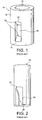
- Figure 1 shows a sleeve member 10 of the type used as a metering valve sleeve in a metering valve arrangement for controlling the rate of flow of fuel to an engine.
- the metering valve arrangement is operable under the control of a governor to vary the fuelling level of the engine in response to variations in engine load.
- the metering valve sleeve 10 is provided with an internal through bore 12 to define a tubular wall 14 having internal and external cylindrical surfaces, and in which an opening 16 is provided to define an outlet port for a fluid flow.
- the opening 16 in the tubular wall 14 is conveniently formed using the conventional technique of rotating a grinding disc or milling wheel (not shown in Figure 1) such that the disc impacts the cylindrical outer surface of the sleeve 10 and grinds away a region of the sleeve to define the opening 16.
- the opening 16 has, at the internal surface 14 or the wall of the sleeve 10, a periphery having upper and lower edges 18 that are convex to the longitudinal axis of the opening 16.
- the periphery of the opening 16 at the outer surface of the tubular wall 14 also has a periphery having upper and lower edges 22 that are convex to the longitudinal axis of the opening 16.
- the opening 16 defines an outlet port through which fuel flows to the engine when the metering valve arrangement is in use.
- Figure 2 shows a metering valve member that, in use, is inserted into the internal bore 12 of the metering valve sleeve 10.
- the metering valve member 24 is provided with a recess or groove 26 which, when in use, cooperates with the opening 16 provided in the metering valve sleeve 10 to vary the rate at which fuel is able to flow through the metering valve arrangement, depending on the angular position of the metering valve member 24 within the sleeve 10.
- the degree of overlap between the recess 26 and the opening 16 can be varied to vary the fuel flow rate through the valve.
- the recess 26 has an outer periphery 28 at the outer surface of the metering valve member 24 having an upper edge 30 concave to the longitudinal axis of the recess 26. It is known to form the recess 26 in the metering valve member 24 using the same technique as described previously for the opening 16 in the sleeve 10, whereby a grinding wheel impacts the cylindrical outer surface of the metering valve member 24 to remove a region of the member 24 to define the recess 26.
- the opening 16 in the metering valve sleeve 10 at the internal bore 12 has an outer periphery 28 of generally square or rectangular form and, in addition, if the outer periphery of the opening defined by the recess 26 in the metering valve member 24, which cooperates with the opening 16, is of partially square or rectangular form.
- the aforementioned technique for forming the opening 16 in the sleeve member 10 and the recess 26 in the metering valve member 24 it is not possible to produce an opening or recess having a periphery of this shape.
- the present invention overcomes this problem by mounting a grinding wheel 32 upon a drive shaft 35 having a drive axis 33, and providing the grinding wheel 32 with an outer circumferential surface 34 concave to a diametrical axis 37 of the wheel 32, the axis 37 being substantially orthogonal to the drive axis 33.
- the wheel 32 also includes and first and second opposing radial surfaces 36, 38 respectively of substantially planar form, which face along the drive axis 33 in opposite directions.
- Figure 4 shows the grinding wheel 32 when it is engaged with the cylindrical outer surface of the sleeve member 10 during the grinding process.
- the drive shaft. 35 is rotated to rotate the grinding wheel 32, thereby causing a region of the sleeve 10 to be ground.
- the grinding process is continued until the grinding wheel 32 forms a recess in the sleeve member 10 that extends fully through the tubular wall 14 to define an opening 40 therein.
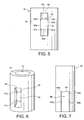
- the peripheral surface 34 of the grinding wheel 32 is shaped such that an outer periphery 42 of the opening 40 formed at the internal surface of the tubular wall 14 of the sleeve 10 is of substantially rectangular form, the periphery 42 of the opening 40 having four substantially square corners 41a, 41b, 41c, 41d. Facing pairs of edges 43a, 43b and 43c, 43d of the periphery 42 are formed substantially parallel to one another by virtue of the planar radial surfaces 36, 38 of the disc 32.
- the metering valve sleeve 10 usually takes the form of a tubular sleeve, having external and internal surfaces of substantially cylindrical form. It will be appreciated, however, that the shape of the outer surface of the sleeve 10 does not matter, and that providing the internal surface of the sleeve wall 14 is cylindrical, appropriate shaping of the grinding wheel, as described previously, will produce the required profile for the opening at the internal surface of the sleeve 10.
- the method described previously may also be used to provide a recess 46 in the metering valve member 24 of the metering valve arrangement, as shown in Figure 7, wherein the recess 46 has a periphery 48 having two substantially square corners 49a, 49b.
- the periphery 48 is also formed with two substantially parallel facing edges 47a, 47b by virtue of the planar radial surfaces 36, 38 of the grinding wheel (as shown in Figures 3 and 4). In this case, the grinding process is continued until a region of the metering valve member 24 is removed to define a recess 46 of the required size.
- the opening of the recess 46 defined in the metering valve member 24 only has two square corners 49a, 49b, as opposed to the four square corners 41a, 41b, 41c, 41d of the recess in the sleeve 10, as the metering valve member 24 is ground at an end region thereof, whereas a central region of sleeve 10 is ground between opposing sleeve ends.
- whether the periphery of the opening 16 at the internal bore 12 of the sleeve 10 is an exact square or rectangular in shape will be determined by the diameter of the bore 12 and the extent to which the surface 34 of the wheel 32 is concave.
- the present invention provides a convenient method of forming openings of at least partially rectangular or square form in both the metering valve sleeve 10 and the metering valve member 24 of a metering valve arrangement to define ports for a fluid flow. It has been found that advantages are obtained if the outer periphery 48 of the recess 46 in the metering valve member 24 and the outer periphery 42 of the opening 40 in the metering valve sleeve 10 are of generally square or rectangular form, as the sensitivity of the metering valve arrangement is improved.
- the extent to which the circumferential surface 34 of the grinding wheel 32 should be made concave will be determined by the internal diameter of the bore 12.
- the method is used to provide a recess 46 in the metering valve member 24 to define an opening having a periphery 48 including two substantially square corners, the extent to which the outer surface 34 of the grinding wheel 32 should be made concave will be determined by the diameter of the cylindrical outer surface of the metering valve member 24.
- the grinding wheel itself is worn away and therefore needs to be continuously or intermittently reshaped.
- the circumferential surface 34 of the grinding wheel 32 may be shaped by means of a dresser (not shown) mounted in a conventional manner on the opposite side of the wheel 32 to the sleeve 10.
- the dimensions of the dresser are chosen to ensure that the extent to which the outer surface 34 of the wheel is shaped concave will give a substantially square or rectangular opening, at the desired surface, for the diameter of the component to be ground.
- Figure 8 shows a plan view of a metering valve member 24 having a radius, R, in which an opening having an outer periphery of substantially rectangular form is to be formed.
- the following equations show the relationship between various dimensions of the metering valve member 24 and the grinding wheel 32 identified in Figure 8.
- the equations enable a value to be calculated for r3, the radius of the dresser, for a port or opening in the valve member 24 having a width, W, and a height, H.
- Figure 9 shows a side view of the metering valve member 24 and the grinding wheel 32, in which c is depth from the centre axis of the grinding wheel 32 at the centreline, b is the depth from the centre axis of the grinding wheel 32 at its outermost edge, r1 is the radius of the grinding wheel 32 to the edge of the grinding wheel 32, r2 is the radius to the midpoint of the concave outer circumference of the grinding wheel 32 and y is equal to half of the height, H, of the opening 48.
- a grinding wheel 32 to remove a portion of a metering valve sleeve 10 or a portion of a metering valve member 24
- a toothed milling wheel instead to remove the required body portion.
- a milling wheel if the body within which the opening is provided is formed from a relatively soft material. Any reference to 'grinding is therefore intended to include processes such as milling, or other similar processes, which rely on relative rotation between engaged parts to create an opening in a body.
- the present invention is not limited to use in providing openings of square or rectangular form in metering valve components, but may be applied to any component formed from a metal or any other material suitable for grinding or milling, which includes a region of generally cylindrical form.
Landscapes
- Engineering & Computer Science (AREA)
- Mechanical Engineering (AREA)
- Grinding And Polishing Of Tertiary Curved Surfaces And Surfaces With Complex Shapes (AREA)
- Crystals, And After-Treatments Of Crystals (AREA)
- Grinding Of Cylindrical And Plane Surfaces (AREA)
- Manufacturing Of Printed Circuit Boards (AREA)
Abstract
Description
- The invention relates to a method of forming a recess in a body. In particular, but not exclusively, the invention relates to a method of forming a recess in a metal body to define an opening having an outer periphery of at least partially square or rectangular form.
- In a metering valve arrangement of the type used to control fuelling of a compression ignition internal combustion engine, a metering valve member is angularly adjustable within a bore of a metering valve sleeve to vary the degree of overlap between a recess or channel provided in the metering valve member and an outlet port provided in the sleeve so as to vary the rate of flow of fuel to the engine. The metering valve member is of generally solid, cylindrical form except for the provision of the recess. It is known that the sensitivity of the metering valve arrangement is improved if both the outer periphery of the recess in the metering valve member and that of the outlet port in the sleeve with which the recess cooperates are of substantially square or rectangular form.
- It has been proposed to use a spark erosion technique using an Electric Discharge Machine (EDM) to form ports or openings of square or rectangular form in the above mentioned components. However, such techniques are time consuming and the manufacturing cost per item is high, and so they are not suitable for large scale manufacture of such items. It has also been proposed to use injection moulding techniques to form such square or rectangular ports but, again, the associated manufacturing costs are prohibitive.
- According to the present invention, there is provided a method of forming a recess in a body having a cylindrical surface, the method comprising:
- providing a grinding wheel having a first axis, a circumferential surface concave to a second axis that is substantially orthogonal to the first axis and first and second opposing radial surfaces of substantially planar form,
- engaging at least a portion of the circumferential surface of the grinding wheel with an outer surface of the body, and
- rotating the grinding wheel and the body relative to one another about the first axis to cause a region of the body to be ground by said wheel, thereby to define a recess in the body, having a periphery at the cylindrical surface thereof, which includes at least two substantially square corners and at least one pair of substantially parallel facing edges.
-
- For the purpose of this specification, the phrase 'grinding' shall be taken to refer to any process by which material is ground, milled or otherwise removed from a body through engagement between a rotatable grinding element and the body, and shall therefore be taken to include processes commonly referred to as milling processes in which a toothed milling wheel or disc is brought into engagement with the body and relative rotational movement between the milling wheel and the body causes removal of a portion of the body.
- In a preferred embodiment, the first axis forms a drive axis, and the method includes the step of rotating the grinding wheel about the first axis to provide said relative rotation between the grinding wheel and the body. As an alternative, or in addition, the body itself may be rotated or otherwise moved relative to the wheel to provide said relative rotation.
- In one embodiment of the invention, the body may be of substantially solid form and may, for example, take the form of a metering valve member for a metering valve arrangement, having a substantially cylindrical outer surface.
- If the method is used to provided a recess in a metering valve member having a substantially cylindrical outer surface, an end region of the metering valve member may be ground such that the recess extends to an end surface of the metering valve member and has an outer periphery at the outer surface of the metering valve member having only two square corners.
- In an alternative embodiment of the invention, the body may be provided with an internal bore defining a tubular wall having a substantially cylindrical internal surface, and the method may comprise the step of rotating the grinding wheel and the body relative to one another until the recess extends through the tubular wall to define an opening having a periphery at the internal surface of the wall that includes at least two substantially square corners. For example, the body may take the form of a metering valve sleeve for a metering valve member.
- The method may be used to provide a recess in a region of the body intermediate opposing end regions of the body such that the recess has a periphery at the internal surface of the tubular wall having four substantially square corners, and two pairs of substantially parallel facing edges, such that the periphery is substantially square or rectangular in shape.
- In one preferred embodiment, the circumferential surface of the grinding wheel is shaped such that the outer periphery of the opening defined in the tubular wall has a periphery at the internal surface of the wall having four substantially square corners, and two pairs of substantially parallel facing edges.
- It has been found that the provision of cooperable openings of square or rectangular form in the valve member and the sleeve components of a metering valve arrangement improves the sensitivity of the valve.
- The body to be ground extends along a further axis, the method preferably comprising the step of rotating the grinding wheel about a first axis which is substantially perpendicular to the further axis.
- If required, the method may include the further step of punching or otherwise finishing the periphery to remove any slight anomalies at the corners if they are not quite square.
- The present invention provides a convenient method of forming a square or rectangular recess or opening in a metering valve component, and is suitable for large scale component production. In general the method may be utilised for the formation of recesses or openings of square or rectangular form in any component formed from metal, or another material suitable for grinding.
- The invention will now be described, by way of example only, with reference to the accompanying drawings in which:
- Figure 1 is a perspective view of a metering valve sleeve provided with an opening which, at an internal bore of the sleeve, has two facing peripheral edges of convex form,
- Figure 2 is a perspective view of a metering valve member provided with a recess defining an opening having an upper peripheral edge of concave form,
- Figure 3 is a perspective view of a rotatable grinding wheel of the type used in the method of the present invention,
- Figure 4 is a perspective view of the grinding wheel in Figure 3 when in use in the method of the present invention,
- Figure 5 is a front view of a metering valve sleeve provided with an opening of rectangular form,
- Figure 6 is a perspective view of the metering valve sleeve in Figure 5, and
- Figure 7 is a front view of a metering valve member provided with an opening having a periphery of rectangular form.
-
- Figure 1 shows a
sleeve member 10 of the type used as a metering valve sleeve in a metering valve arrangement for controlling the rate of flow of fuel to an engine. Typically, the metering valve arrangement is operable under the control of a governor to vary the fuelling level of the engine in response to variations in engine load. Themetering valve sleeve 10 is provided with an internal throughbore 12 to define atubular wall 14 having internal and external cylindrical surfaces, and in which anopening 16 is provided to define an outlet port for a fluid flow. The opening 16 in thetubular wall 14 is conveniently formed using the conventional technique of rotating a grinding disc or milling wheel (not shown in Figure 1) such that the disc impacts the cylindrical outer surface of thesleeve 10 and grinds away a region of the sleeve to define theopening 16. Using this technique, theopening 16 has, at theinternal surface 14 or the wall of thesleeve 10, a periphery having upper andlower edges 18 that are convex to the longitudinal axis of theopening 16. The periphery of theopening 16 at the outer surface of thetubular wall 14 also has a periphery having upper andlower edges 22 that are convex to the longitudinal axis of theopening 16. Theopening 16 defines an outlet port through which fuel flows to the engine when the metering valve arrangement is in use. - Figure 2 shows a metering valve member that, in use, is inserted into the
internal bore 12 of themetering valve sleeve 10. Themetering valve member 24 is provided with a recess orgroove 26 which, when in use, cooperates with theopening 16 provided in themetering valve sleeve 10 to vary the rate at which fuel is able to flow through the metering valve arrangement, depending on the angular position of themetering valve member 24 within thesleeve 10. By varying the angular position of themetering valve member 24 within thebore 12, the degree of overlap between therecess 26 and theopening 16 can be varied to vary the fuel flow rate through the valve. As can be seen in Figure 2, therecess 26 has anouter periphery 28 at the outer surface of themetering valve member 24 having anupper edge 30 concave to the longitudinal axis of therecess 26. It is known to form therecess 26 in themetering valve member 24 using the same technique as described previously for theopening 16 in thesleeve 10, whereby a grinding wheel impacts the cylindrical outer surface of themetering valve member 24 to remove a region of themember 24 to define therecess 26. - It has been found that advantages are obtained if the opening 16 in the
metering valve sleeve 10 at theinternal bore 12 has anouter periphery 28 of generally square or rectangular form and, in addition, if the outer periphery of the opening defined by therecess 26 in themetering valve member 24, which cooperates with the opening 16, is of partially square or rectangular form. Using the aforementioned technique for forming the opening 16 in thesleeve member 10 and the recess 26 in themetering valve member 24, it is not possible to produce an opening or recess having a periphery of this shape. - Referring to Figures 3 and 4, the present invention overcomes this problem by mounting a
grinding wheel 32 upon adrive shaft 35 having adrive axis 33, and providing thegrinding wheel 32 with an outercircumferential surface 34 concave to a diametrical axis 37 of thewheel 32, the axis 37 being substantially orthogonal to thedrive axis 33. Thewheel 32 also includes and first and second opposingradial surfaces drive axis 33 in opposite directions. Figure 4 shows thegrinding wheel 32 when it is engaged with the cylindrical outer surface of thesleeve member 10 during the grinding process. The drive shaft. 35 is rotated to rotate thegrinding wheel 32, thereby causing a region of thesleeve 10 to be ground. The grinding process is continued until thegrinding wheel 32 forms a recess in thesleeve member 10 that extends fully through thetubular wall 14 to define anopening 40 therein. As shown in Figures 5 and 6, theperipheral surface 34 of thegrinding wheel 32 is shaped such that anouter periphery 42 of theopening 40 formed at the internal surface of thetubular wall 14 of thesleeve 10 is of substantially rectangular form, theperiphery 42 of the opening 40 having four substantiallysquare corners edges periphery 42 are formed substantially parallel to one another by virtue of the planarradial surfaces disc 32. - The
metering valve sleeve 10 usually takes the form of a tubular sleeve, having external and internal surfaces of substantially cylindrical form. It will be appreciated, however, that the shape of the outer surface of thesleeve 10 does not matter, and that providing the internal surface of thesleeve wall 14 is cylindrical, appropriate shaping of the grinding wheel, as described previously, will produce the required profile for the opening at the internal surface of thesleeve 10. - The method described previously may also be used to provide a
recess 46 in themetering valve member 24 of the metering valve arrangement, as shown in Figure 7, wherein therecess 46 has aperiphery 48 having two substantiallysquare corners periphery 48 is also formed with two substantially parallel facingedges radial surfaces metering valve member 24 is removed to define arecess 46 of the required size. It will be appreciated that the opening of therecess 46 defined in themetering valve member 24 only has twosquare corners square corners sleeve 10, as themetering valve member 24 is ground at an end region thereof, whereas a central region ofsleeve 10 is ground between opposing sleeve ends. In the aforedescribed example, whether the periphery of theopening 16 at theinternal bore 12 of thesleeve 10 is an exact square or rectangular in shape will be determined by the diameter of thebore 12 and the extent to which thesurface 34 of thewheel 32 is concave. - The present invention provides a convenient method of forming openings of at least partially rectangular or square form in both the
metering valve sleeve 10 and themetering valve member 24 of a metering valve arrangement to define ports for a fluid flow. It has been found that advantages are obtained if theouter periphery 48 of therecess 46 in themetering valve member 24 and theouter periphery 42 of the opening 40 in themetering valve sleeve 10 are of generally square or rectangular form, as the sensitivity of the metering valve arrangement is improved. - When the method is used to provide a square or rectangular opening at the
internal bore 12 of themetering valve sleeve 10, it will be appreciated that the extent to which thecircumferential surface 34 of thegrinding wheel 32 should be made concave will be determined by the internal diameter of thebore 12. Likewise, when the method is used to provide arecess 46 in themetering valve member 24 to define an opening having aperiphery 48 including two substantially square corners, the extent to which theouter surface 34 of thegrinding wheel 32 should be made concave will be determined by the diameter of the cylindrical outer surface of themetering valve member 24. In use, as the grindingwheel 32 grinds away themetering valve sleeve 10, the grinding wheel itself is worn away and therefore needs to be continuously or intermittently reshaped. Thecircumferential surface 34 of thegrinding wheel 32 may be shaped by means of a dresser (not shown) mounted in a conventional manner on the opposite side of thewheel 32 to thesleeve 10. The dimensions of the dresser are chosen to ensure that the extent to which theouter surface 34 of the wheel is shaped concave will give a substantially square or rectangular opening, at the desired surface, for the diameter of the component to be ground. - Figure 8 shows a plan view of a
metering valve member 24 having a radius, R, in which an opening having an outer periphery of substantially rectangular form is to be formed. The following equations show the relationship between various dimensions of themetering valve member 24 and thegrinding wheel 32 identified in Figure 8. The equations enable a value to be calculated for r3, the radius of the dresser, for a port or opening in thevalve member 24 having a width, W, and a height, H.r r y grinding wheel 32, x is equal to half the port width, W, and z is the distance from the centre of thegrinding wheel 32 to the centre of themetering valve member 24. - Figure 9 shows a side view of the
metering valve member 24 and thegrinding wheel 32, in which c is depth from the centre axis of thegrinding wheel 32 at the centreline, b is the depth from the centre axis of thegrinding wheel 32 at its outermost edge, r1 is the radius of thegrinding wheel 32 to the edge of thegrinding wheel 32, r2 is the radius to the midpoint of the concave outer circumference of thegrinding wheel 32 and y is equal to half of the height, H, of theopening 48. - By way of example, typical dimensions (in millimetres) identified in Figure 8 are as follows; R=3.1775, x=I1.5 (W=3.0), y=6.4 (H= 12.8), a = 2.8012, r1=15.0, b=13.5661, c=13.1898, r2=14.6605 and z=16.3673. To form a 3.0 (W) x 12.8 (H) nun opening in the
metering valve member 24, the radius r3 of the dresser should therefore be 3.4836 mm. - It will be appreciated that the above equations can also be applied to calculate the radius, r3, required for the dresser if a square or
rectangular port 42 is to be formed at the inner surface of thebore 12 in the metering valve sleeve 10 (as shown in Figure 6). - Although the method described previously is described as employing a rotatable grinding wheel or
disc 32 for engagement a fixedbody 10/24, for some applications removal of the required portion of the body to define the opening may be achieved by any form of relative rotation between the body and the wheel (e.g. by rotating thebody 10, 24). - Additionally, although the method described above involves the use of a
grinding wheel 32 to remove a portion of ametering valve sleeve 10 or a portion of ametering valve member 24, it will be appreciated that for certain materials is may be more convenient to use a toothed milling wheel instead to remove the required body portion. For example, it may be more appropriate to use a milling wheel if the body within which the opening is provided is formed from a relatively soft material. Any reference to 'grinding is therefore intended to include processes such as milling, or other similar processes, which rely on relative rotation between engaged parts to create an opening in a body. - The present invention is not limited to use in providing openings of square or rectangular form in metering valve components, but may be applied to any component formed from a metal or any other material suitable for grinding or milling, which includes a region of generally cylindrical form.
Claims (12)
- A method of forming a recess in a body (10; 24) having a surface of substantially cylindrical form, the method comprising:providing a grinding wheel (32) having a first axis (33), a circumferential surface (34) concave to a second axis (37) which is substantially orthogonal to the first axis (33) and first and second opposing radial surfaces (36, 38) of substantially planar form,engaging at least a portion of the circumferential surface (34) of the grinding wheel (32) with an outer surface of the body (10; 24), androtating the grinding wheel (32) and the body (10; 24) relative to one another to cause a region of the body (10; 24) to be ground by said wheel (32), thereby to define a recess (40, 46) in the body, having a periphery ( 42, 48) at the cylindrical surface thereof, which includes at least two substantially square corners (41a-41d; 49a, 49b) and at least one pair of substantially parallel facing edges (43a-43d; 47a, 47b).
- The method as claimed in Claim 1, including the step of rotating the grinding wheel (32) about the first axis (33) to provide said relative rotation between the grinding wheel (32) and the body (10).
- The method as claimed in Claim 1 or 2, wherein the body takes the form of a metering valve member (24) having a substantially cylindrical outer surface.
- The method as claimed in Claim 3, comprising grinding the cylindrical outer surface of the metering valve member (24) at an end region thereof to define a recess (46), which extends to an end surface of the end region, having a periphery (48) at the outer surface of the metering valve member (24) with two substantially square corners (49a, 49b).
- The method as claimed in any one of Claims 1 to 4, wherein the body (10) is provided with an internal bore (12) to define a tubular wall (14) having a cylindrical internal surface, the method comprising rotating at least one of the grinding wheel (32) and the body (10) until the recess extends through the tubular wall (14) to define an opening (40) therein.
- The method as claimed in Claim 5, wherein the circumferential surface of the grinding wheel (32) is shaped such that the opening (40) defined in the tubular wall (14) has a periphery (42) at the internal surface of the wall (14) that includes at least two substantially square corners (41a, 41b, 41c, 41d).
- The method as claimed in Claim 6, comprising the step of grinding a region of the body (10) intermediate opposing end regions of the body to define an opening (40) having a periphery (42) at the internal surface of the tubular wall (14) having four substantially square corners (41-41d).
- The method as claimed in Claim 7, wherein the periphery (42) of the opening (40) is substantially square.
- The method as claimed in Claim 7, wherein the periphery (42) of the opening (40) is substantially rectangular.
- The method as claimed in Claim 8 or Claim 9, wherein the body takes the form of a metering valve sleeve (10) for a metering valve member.
- The method as claimed in any one of Claims 5 to 10, wherein the tubular wall (14) has a substantially cylindrical outer surface for engagement with the grinding wheel (32).
- The method as claimed in any one of Claims 1 to 11, wherein the axis of the body (10, 24) is arranged to be substantially perpendicular to the first axis (33) of the grinding wheel (32).
Applications Claiming Priority (2)
| Application Number | Priority Date | Filing Date | Title |
|---|---|---|---|
| GBGB0128925.5A GB0128925D0 (en) | 2001-11-29 | 2001-11-29 | Method of forming a recess in a body |
| GB0128925 | 2001-11-29 |
Publications (2)
| Publication Number | Publication Date |
|---|---|
| EP1316392A1 true EP1316392A1 (en) | 2003-06-04 |
| EP1316392B1 EP1316392B1 (en) | 2005-06-15 |
Family
ID=32843226
Family Applications (1)
| Application Number | Title | Priority Date | Filing Date |
|---|---|---|---|
| EP02257950A Expired - Lifetime EP1316392B1 (en) | 2001-11-29 | 2002-11-19 | Method of forming a recess in a body |
Country Status (5)
| Country | Link |
|---|---|
| US (1) | US6773336B2 (en) |
| EP (1) | EP1316392B1 (en) |
| AT (1) | ATE297835T1 (en) |
| DE (1) | DE60204647T2 (en) |
| GB (1) | GB0128925D0 (en) |
Cited By (1)
| Publication number | Priority date | Publication date | Assignee | Title |
|---|---|---|---|---|
| CN110425188A (en) * | 2019-07-16 | 2019-11-08 | 北京实验工厂有限责任公司 | A kind of stainless steel material Servo Valve's Slide Valve pair couple surface treatment method |
Families Citing this family (1)
| Publication number | Priority date | Publication date | Assignee | Title |
|---|---|---|---|---|
| JP1556818S (en) * | 2015-10-28 | 2016-08-22 |
Citations (6)
| Publication number | Priority date | Publication date | Assignee | Title |
|---|---|---|---|---|
| US2384800A (en) * | 1942-01-22 | 1945-09-18 | Claude E Cox | Method of forming flowmeter tube mandrels |
| FR923640A (en) * | 1946-02-08 | 1947-07-11 | Cutting machine by generation | |
| DE871709C (en) * | 1940-08-20 | 1953-03-26 | Daimler Benz Ag | Device for the preparation of bar material, especially for hardness testing |
| US3545336A (en) * | 1969-04-08 | 1970-12-08 | Charley Savko | Apparatus for forming slits in an elongated linearly moving tube |
| US4170975A (en) * | 1976-10-07 | 1979-10-16 | Robert Bosch Gmbh | Fuel metering valve assembly for internal combustion engines |
| US5853316A (en) * | 1994-10-19 | 1998-12-29 | Ina Walzlager Schaeffler Ohg | Method of and apparatus for grinding control edges of a control bush |
Family Cites Families (5)
| Publication number | Priority date | Publication date | Assignee | Title |
|---|---|---|---|---|
| US2772524A (en) * | 1956-01-27 | 1956-12-04 | John F Kopczynski | Abrasive grinders |
| FR2174350A5 (en) | 1972-02-29 | 1973-10-12 | Gresset Andre | |
| SE447714B (en) | 1984-04-26 | 1986-12-08 | Finsliparna Ab | GRINDING DISK FOR GRIPPING CUTTER DRILL |
| US4977709A (en) | 1989-05-19 | 1990-12-18 | Inovac Ab | Abrasive wheel |
| US6358133B1 (en) * | 1998-02-06 | 2002-03-19 | 3M Innovative Properties Company | Grinding wheel |
-
2001
- 2001-11-29 GB GBGB0128925.5A patent/GB0128925D0/en not_active Ceased
-
2002
- 2002-11-19 DE DE60204647T patent/DE60204647T2/en not_active Expired - Lifetime
- 2002-11-19 AT AT02257950T patent/ATE297835T1/en not_active IP Right Cessation
- 2002-11-19 EP EP02257950A patent/EP1316392B1/en not_active Expired - Lifetime
- 2002-11-25 US US10/303,234 patent/US6773336B2/en not_active Expired - Lifetime
Patent Citations (6)
| Publication number | Priority date | Publication date | Assignee | Title |
|---|---|---|---|---|
| DE871709C (en) * | 1940-08-20 | 1953-03-26 | Daimler Benz Ag | Device for the preparation of bar material, especially for hardness testing |
| US2384800A (en) * | 1942-01-22 | 1945-09-18 | Claude E Cox | Method of forming flowmeter tube mandrels |
| FR923640A (en) * | 1946-02-08 | 1947-07-11 | Cutting machine by generation | |
| US3545336A (en) * | 1969-04-08 | 1970-12-08 | Charley Savko | Apparatus for forming slits in an elongated linearly moving tube |
| US4170975A (en) * | 1976-10-07 | 1979-10-16 | Robert Bosch Gmbh | Fuel metering valve assembly for internal combustion engines |
| US5853316A (en) * | 1994-10-19 | 1998-12-29 | Ina Walzlager Schaeffler Ohg | Method of and apparatus for grinding control edges of a control bush |
Non-Patent Citations (1)
| Title |
|---|
| "NUTEN SCHLEIFEN STATT FRASEN", WERKSTATT UND BETRIEB, CARL HANSER VERLAG. MUNCHEN, DE, VOL. 122, NR. 9, PAGE(S) 733, ISSN: 0043-2792, XP000084119 * |
Cited By (2)
| Publication number | Priority date | Publication date | Assignee | Title |
|---|---|---|---|---|
| CN110425188A (en) * | 2019-07-16 | 2019-11-08 | 北京实验工厂有限责任公司 | A kind of stainless steel material Servo Valve's Slide Valve pair couple surface treatment method |
| CN110425188B (en) * | 2019-07-16 | 2020-10-23 | 北京实验工厂有限责任公司 | Surface treatment method for sliding valve auxiliary part of stainless steel servo valve |
Also Published As
| Publication number | Publication date |
|---|---|
| ATE297835T1 (en) | 2005-07-15 |
| DE60204647D1 (en) | 2005-07-21 |
| EP1316392B1 (en) | 2005-06-15 |
| GB0128925D0 (en) | 2002-01-23 |
| DE60204647T2 (en) | 2006-05-11 |
| US6773336B2 (en) | 2004-08-10 |
| US20030109203A1 (en) | 2003-06-12 |
Similar Documents
| Publication | Publication Date | Title |
|---|---|---|
| US5307708A (en) | Camshaft for controlling valves in internal combustion engines | |
| US5012706A (en) | Socket wrench opening | |
| US4553948A (en) | Oil pressure type pneumatic torque wrench | |
| CN104985571B (en) | Work head | |
| EP1142656B1 (en) | Pipe shaping method | |
| US8221195B2 (en) | Process for grinding dies | |
| US5632576A (en) | Cutting plate for a ball head miller | |
| Guo et al. | Influences of tool setting errors on gear skiving accuracy | |
| US4967852A (en) | Oil pressure type impulse torque generator for wrench | |
| EP1316392B1 (en) | Method of forming a recess in a body | |
| JPH068032A (en) | Fixing blade | |
| KR102169824B1 (en) | Gear cutter with radial adjustability of stick blades | |
| US6427568B1 (en) | Method to prevent or reduce formation of magnetism in two adjacently located saw blades rotating in opposed directions, and a device for utilization of the method | |
| RU2091707C1 (en) | Plant to manufacture rotary valve for hydraulic power-assisted steering gear | |
| JP3390003B2 (en) | Machines used to manufacture power steering mechanisms for vehicles | |
| US6936213B1 (en) | Adjustment of relative positions of machine components | |
| US3930482A (en) | Fuel injection piston and method of its manufacture | |
| EP0065426B1 (en) | Scroll manufacturing tool | |
| US6591715B2 (en) | End mill type gear cutters for spindle driven machines | |
| US6446338B1 (en) | Method of sluice gate valve fabrication | |
| CA2146575A1 (en) | Improvements in or relating to the manufacture of rotary valves | |
| JP2010000569A (en) | Grinder and cutting device | |
| JP7793178B2 (en) | Gear finishing grinding wheel and its manufacturing method | |
| JPH01167021A (en) | Processing method for cylinder of engine | |
| SU874263A2 (en) | Device for dynamic chip-breaking |
Legal Events
| Date | Code | Title | Description |
|---|---|---|---|
| PUAI | Public reference made under article 153(3) epc to a published international application that has entered the european phase |
Free format text: ORIGINAL CODE: 0009012 |
|
| AK | Designated contracting states |
Designated state(s): AT BE BG CH CY CZ DE DK EE ES FI FR GB GR IE IT LI LU MC NL PT SE SK TR |
|
| AX | Request for extension of the european patent |
Extension state: AL LT LV MK RO SI |
|
| 17P | Request for examination filed |
Effective date: 20031119 |
|
| AKX | Designation fees paid |
Designated state(s): AT BE BG CH CY CZ DE DK EE ES FI FR GB GR IE IT LI LU MC NL PT SE SK TR |
|
| 17Q | First examination report despatched |
Effective date: 20040220 |
|
| GRAP | Despatch of communication of intention to grant a patent |
Free format text: ORIGINAL CODE: EPIDOSNIGR1 |
|
| GRAS | Grant fee paid |
Free format text: ORIGINAL CODE: EPIDOSNIGR3 |
|
| GRAA | (expected) grant |
Free format text: ORIGINAL CODE: 0009210 |
|
| AK | Designated contracting states |
Kind code of ref document: B1 Designated state(s): AT BE BG CH CY CZ DE DK EE ES FI FR GB GR IE IT LI LU MC NL PT SE SK TR |
|
| PG25 | Lapsed in a contracting state [announced via postgrant information from national office to epo] |
Ref country code: AT Free format text: LAPSE BECAUSE OF FAILURE TO SUBMIT A TRANSLATION OF THE DESCRIPTION OR TO PAY THE FEE WITHIN THE PRESCRIBED TIME-LIMIT Effective date: 20050615 Ref country code: LI Free format text: LAPSE BECAUSE OF FAILURE TO SUBMIT A TRANSLATION OF THE DESCRIPTION OR TO PAY THE FEE WITHIN THE PRESCRIBED TIME-LIMIT Effective date: 20050615 Ref country code: CZ Free format text: LAPSE BECAUSE OF FAILURE TO SUBMIT A TRANSLATION OF THE DESCRIPTION OR TO PAY THE FEE WITHIN THE PRESCRIBED TIME-LIMIT Effective date: 20050615 Ref country code: CH Free format text: LAPSE BECAUSE OF FAILURE TO SUBMIT A TRANSLATION OF THE DESCRIPTION OR TO PAY THE FEE WITHIN THE PRESCRIBED TIME-LIMIT Effective date: 20050615 Ref country code: TR Free format text: LAPSE BECAUSE OF FAILURE TO SUBMIT A TRANSLATION OF THE DESCRIPTION OR TO PAY THE FEE WITHIN THE PRESCRIBED TIME-LIMIT Effective date: 20050615 Ref country code: SK Free format text: LAPSE BECAUSE OF FAILURE TO SUBMIT A TRANSLATION OF THE DESCRIPTION OR TO PAY THE FEE WITHIN THE PRESCRIBED TIME-LIMIT Effective date: 20050615 Ref country code: EE Free format text: LAPSE BECAUSE OF FAILURE TO SUBMIT A TRANSLATION OF THE DESCRIPTION OR TO PAY THE FEE WITHIN THE PRESCRIBED TIME-LIMIT Effective date: 20050615 Ref country code: BE Free format text: LAPSE BECAUSE OF FAILURE TO SUBMIT A TRANSLATION OF THE DESCRIPTION OR TO PAY THE FEE WITHIN THE PRESCRIBED TIME-LIMIT Effective date: 20050615 Ref country code: FI Free format text: LAPSE BECAUSE OF FAILURE TO SUBMIT A TRANSLATION OF THE DESCRIPTION OR TO PAY THE FEE WITHIN THE PRESCRIBED TIME-LIMIT Effective date: 20050615 Ref country code: NL Free format text: LAPSE BECAUSE OF FAILURE TO SUBMIT A TRANSLATION OF THE DESCRIPTION OR TO PAY THE FEE WITHIN THE PRESCRIBED TIME-LIMIT Effective date: 20050615 |
|
| REG | Reference to a national code |
Ref country code: GB Ref legal event code: FG4D Ref country code: CH Ref legal event code: EP |
|
| REF | Corresponds to: |
Ref document number: 60204647 Country of ref document: DE Date of ref document: 20050721 Kind code of ref document: P |
|
| REG | Reference to a national code |
Ref country code: IE Ref legal event code: FG4D |
|
| PG25 | Lapsed in a contracting state [announced via postgrant information from national office to epo] |
Ref country code: DK Free format text: LAPSE BECAUSE OF FAILURE TO SUBMIT A TRANSLATION OF THE DESCRIPTION OR TO PAY THE FEE WITHIN THE PRESCRIBED TIME-LIMIT Effective date: 20050915 Ref country code: SE Free format text: LAPSE BECAUSE OF FAILURE TO SUBMIT A TRANSLATION OF THE DESCRIPTION OR TO PAY THE FEE WITHIN THE PRESCRIBED TIME-LIMIT Effective date: 20050915 Ref country code: BG Free format text: LAPSE BECAUSE OF FAILURE TO SUBMIT A TRANSLATION OF THE DESCRIPTION OR TO PAY THE FEE WITHIN THE PRESCRIBED TIME-LIMIT Effective date: 20050915 Ref country code: GR Free format text: LAPSE BECAUSE OF FAILURE TO SUBMIT A TRANSLATION OF THE DESCRIPTION OR TO PAY THE FEE WITHIN THE PRESCRIBED TIME-LIMIT Effective date: 20050915 |
|
| PG25 | Lapsed in a contracting state [announced via postgrant information from national office to epo] |
Ref country code: ES Free format text: LAPSE BECAUSE OF FAILURE TO SUBMIT A TRANSLATION OF THE DESCRIPTION OR TO PAY THE FEE WITHIN THE PRESCRIBED TIME-LIMIT Effective date: 20050926 |
|
| PG25 | Lapsed in a contracting state [announced via postgrant information from national office to epo] |
Ref country code: CY Free format text: LAPSE BECAUSE OF FAILURE TO SUBMIT A TRANSLATION OF THE DESCRIPTION OR TO PAY THE FEE WITHIN THE PRESCRIBED TIME-LIMIT Effective date: 20051119 |
|
| PG25 | Lapsed in a contracting state [announced via postgrant information from national office to epo] |
Ref country code: IE Free format text: LAPSE BECAUSE OF NON-PAYMENT OF DUE FEES Effective date: 20051121 |
|
| PG25 | Lapsed in a contracting state [announced via postgrant information from national office to epo] |
Ref country code: PT Free format text: LAPSE BECAUSE OF FAILURE TO SUBMIT A TRANSLATION OF THE DESCRIPTION OR TO PAY THE FEE WITHIN THE PRESCRIBED TIME-LIMIT Effective date: 20051124 |
|
| PG25 | Lapsed in a contracting state [announced via postgrant information from national office to epo] |
Ref country code: LU Free format text: LAPSE BECAUSE OF NON-PAYMENT OF DUE FEES Effective date: 20051130 Ref country code: MC Free format text: LAPSE BECAUSE OF NON-PAYMENT OF DUE FEES Effective date: 20051130 |
|
| NLV1 | Nl: lapsed or annulled due to failure to fulfill the requirements of art. 29p and 29m of the patents act | ||
| REG | Reference to a national code |
Ref country code: CH Ref legal event code: PL |
|
| ET | Fr: translation filed | ||
| PLBE | No opposition filed within time limit |
Free format text: ORIGINAL CODE: 0009261 |
|
| STAA | Information on the status of an ep patent application or granted ep patent |
Free format text: STATUS: NO OPPOSITION FILED WITHIN TIME LIMIT |
|
| 26N | No opposition filed |
Effective date: 20060316 |
|
| REG | Reference to a national code |
Ref country code: IE Ref legal event code: MM4A |
|
| GBPC | Gb: european patent ceased through non-payment of renewal fee |
Effective date: 20061119 |
|
| PG25 | Lapsed in a contracting state [announced via postgrant information from national office to epo] |
Ref country code: GB Free format text: LAPSE BECAUSE OF NON-PAYMENT OF DUE FEES Effective date: 20061119 |
|
| REG | Reference to a national code |
Ref country code: FR Ref legal event code: TP |
|
| REG | Reference to a national code |
Ref country code: FR Ref legal event code: TP Owner name: DELPHI INTERNATIONAL OPERATIONS LUXEMBOURG S.A, LU Effective date: 20140516 |
|
| REG | Reference to a national code |
Ref country code: DE Ref legal event code: R082 Ref document number: 60204647 Country of ref document: DE Representative=s name: MANITZ, FINSTERWALD & PARTNER GBR, DE |
|
| REG | Reference to a national code |
Ref country code: DE Ref legal event code: R081 Ref document number: 60204647 Country of ref document: DE Owner name: DELPHI INTERNATIONAL OPERATIONS LUXEMBOURG S.A, LU Free format text: FORMER OWNER: DELPHI TECHNOLOGIES HOLDING S.A.R.L., BASCHARAGE, LU Effective date: 20140702 Ref country code: DE Ref legal event code: R082 Ref document number: 60204647 Country of ref document: DE Representative=s name: MANITZ, FINSTERWALD & PARTNER GBR, DE Effective date: 20140702 Ref country code: DE Ref legal event code: R082 Ref document number: 60204647 Country of ref document: DE Representative=s name: MANITZ FINSTERWALD PATENTANWAELTE PARTMBB, DE Effective date: 20140702 |
|
| REG | Reference to a national code |
Ref country code: FR Ref legal event code: PLFP Year of fee payment: 14 |
|
| REG | Reference to a national code |
Ref country code: FR Ref legal event code: PLFP Year of fee payment: 15 |
|
| REG | Reference to a national code |
Ref country code: FR Ref legal event code: PLFP Year of fee payment: 16 |
|
| REG | Reference to a national code |
Ref country code: DE Ref legal event code: R082 Ref document number: 60204647 Country of ref document: DE Ref country code: DE Ref legal event code: R081 Ref document number: 60204647 Country of ref document: DE Owner name: DELPHI TECHNOLOGIES IP LIMITED, BB Free format text: FORMER OWNER: DELPHI INTERNATIONAL OPERATIONS LUXEMBOURG S.A R.L., BASCHARAGE, LU |
|
| PGFP | Annual fee paid to national office [announced via postgrant information from national office to epo] |
Ref country code: IT Payment date: 20201123 Year of fee payment: 19 |
|
| PGFP | Annual fee paid to national office [announced via postgrant information from national office to epo] |
Ref country code: DE Payment date: 20211126 Year of fee payment: 20 Ref country code: FR Payment date: 20211124 Year of fee payment: 20 |
|
| REG | Reference to a national code |
Ref country code: DE Ref legal event code: R071 Ref document number: 60204647 Country of ref document: DE |
|
| PG25 | Lapsed in a contracting state [announced via postgrant information from national office to epo] |
Ref country code: IT Free format text: LAPSE BECAUSE OF NON-PAYMENT OF DUE FEES Effective date: 20211119 |
|
| P01 | Opt-out of the competence of the unified patent court (upc) registered |
Effective date: 20230327 |