EP1316363A1 - Internal impingement nozzle - Google Patents
Internal impingement nozzle Download PDFInfo
- Publication number
- EP1316363A1 EP1316363A1 EP02023138A EP02023138A EP1316363A1 EP 1316363 A1 EP1316363 A1 EP 1316363A1 EP 02023138 A EP02023138 A EP 02023138A EP 02023138 A EP02023138 A EP 02023138A EP 1316363 A1 EP1316363 A1 EP 1316363A1
- Authority
- EP
- European Patent Office
- Prior art keywords
- flow divider
- streams
- nozzle
- fluid
- orifice
- Prior art date
- Legal status (The legal status is an assumption and is not a legal conclusion. Google has not performed a legal analysis and makes no representation as to the accuracy of the status listed.)
- Withdrawn
Links
- 239000000463 material Substances 0.000 claims abstract description 45
- 239000012530 fluid Substances 0.000 claims abstract description 38
- 238000000034 method Methods 0.000 claims description 9
- 241000282326 Felis catus Species 0.000 claims description 3
- 230000000295 complement effect Effects 0.000 claims description 2
- 210000000746 body region Anatomy 0.000 description 30
- 239000007921 spray Substances 0.000 description 17
- 239000002245 particle Substances 0.000 description 4
- 239000011347 resin Substances 0.000 description 4
- 229920005989 resin Polymers 0.000 description 4
- 238000005507 spraying Methods 0.000 description 4
- 238000004519 manufacturing process Methods 0.000 description 3
- 239000012855 volatile organic compound Substances 0.000 description 3
- 238000000889 atomisation Methods 0.000 description 2
- 239000000178 monomer Substances 0.000 description 2
- 229910001315 Tool steel Inorganic materials 0.000 description 1
- XAGFODPZIPBFFR-UHFFFAOYSA-N aluminium Chemical compound [Al] XAGFODPZIPBFFR-UHFFFAOYSA-N 0.000 description 1
- 229910052782 aluminium Inorganic materials 0.000 description 1
- 239000000969 carrier Substances 0.000 description 1
- 229910003460 diamond Inorganic materials 0.000 description 1
- 239000010432 diamond Substances 0.000 description 1
- 230000000694 effects Effects 0.000 description 1
- 230000007613 environmental effect Effects 0.000 description 1
- 230000001788 irregular Effects 0.000 description 1
- 239000007788 liquid Substances 0.000 description 1
- 239000003973 paint Substances 0.000 description 1
- 229920000642 polymer Polymers 0.000 description 1
- 229910001220 stainless steel Inorganic materials 0.000 description 1
- 239000010935 stainless steel Substances 0.000 description 1
- UONOETXJSWQNOL-UHFFFAOYSA-N tungsten carbide Chemical compound [W+]#[C-] UONOETXJSWQNOL-UHFFFAOYSA-N 0.000 description 1
Images










Classifications
-
- B—PERFORMING OPERATIONS; TRANSPORTING
- B05—SPRAYING OR ATOMISING IN GENERAL; APPLYING FLUENT MATERIALS TO SURFACES, IN GENERAL
- B05B—SPRAYING APPARATUS; ATOMISING APPARATUS; NOZZLES
- B05B1/00—Nozzles, spray heads or other outlets, with or without auxiliary devices such as valves, heating means
- B05B1/26—Nozzles, spray heads or other outlets, with or without auxiliary devices such as valves, heating means with means for mechanically breaking-up or deflecting the jet after discharge, e.g. with fixed deflectors; Breaking-up the discharged liquid or other fluent material by impinging jets
-
- B—PERFORMING OPERATIONS; TRANSPORTING
- B05—SPRAYING OR ATOMISING IN GENERAL; APPLYING FLUENT MATERIALS TO SURFACES, IN GENERAL
- B05B—SPRAYING APPARATUS; ATOMISING APPARATUS; NOZZLES
- B05B1/00—Nozzles, spray heads or other outlets, with or without auxiliary devices such as valves, heating means
- B05B1/02—Nozzles, spray heads or other outlets, with or without auxiliary devices such as valves, heating means designed to produce a jet, spray, or other discharge of particular shape or nature, e.g. in single drops, or having an outlet of particular shape
- B05B1/04—Nozzles, spray heads or other outlets, with or without auxiliary devices such as valves, heating means designed to produce a jet, spray, or other discharge of particular shape or nature, e.g. in single drops, or having an outlet of particular shape in flat form, e.g. fan-like, sheet-like
- B05B1/042—Outlets having two planes of symmetry perpendicular to each other, one of them defining the plane of the jet
Definitions
- This invention relates to devices for the spraying of fluids. It is disclosed in the context of devices for the spraying of fluid resins, monomers, oligomers, or the like.
- oligomer means a polymer made up of a few monomer units so that it remains fluid However, it may be useful in other applications as well.
- gel coats or other pigmented resins typically requires lower flow rates of these materials than those required to build up the underlying structural layers of such articles.
- external impingement tips designed for such flow rates typically have discharge orifice diameters in the range of about .018" - .023" (about .46 mm. - .58 mm.). These orifices must be disposed in the plane of the spray with tolerances typically on the order of about .001" - .002" (about .025 mm. - .05 mm.) in order to develop a satisfactory spray pattern.
- an apparatus for dispensing a fluid includes a nozzle defining an orifice in a front face of the nozzle, through which orifice the material is discharged.
- the nozzle includes a flow divider cooperating to separate a supply of the material into two streams.
- the flow divider includes two surfaces which intersect not further forward in the nozzle than the front face.
- the two surfaces make substantially equal angles adjacent the orifice to a longitudinal axis of the nozzle.
- the nozzle includes a first feature and the flow divider is formed as a separate component including a second feature.
- the first and second features cooperate to orient the intersection of the two surfaces with respect to the orifice.
- the nozzle includes a first feature and the flow divider includes a second feature cooperating with the first feature to orient the intersection of the two surfaces with respect to the orifice.
- the first feature includes a relief formed in a back side of the front face
- the second feature includes a region of the flow divider for orientation in the relief
- angles are between 20 and 60 degrees. Angles less than 20 degrees and greater than 60 degrees are also useful.
- angles are between 25 and 40 degrees. Angles less than 25 degrees and greater than 40 degrees are also useful.
- the orifice is generally circular transverse to an axis of the nozzle.
- the orifice is generally somewhat oval shaped or cat's eye shaped transverse to an axis of the nozzle.
- Other orifice shapes are also useful, for example, diamond shaped, elliptical, square, and so on.
- the two surfaces include two flat surfaces.
- the surfaces may also be concave, convex or irregular.
- a method of dispensing a fluid includes impinging separate streams of the fluid against each other and substantially simultaneously ejecting the reunited stream through an orifice.
- the method further includes dividing a flow of the fluid into the separate streams using a flow divider.
- Impinging the streams against each other includes impinging the streams against each other at a downstream end of the flow divider.
- impinging the streams against each other at a downstream end of the flow divider includes providing on the flow divider separate surfaces across which the separate streams flow downstream from a point at which the flow divider divides the fluid into separate streams.
- the separate surfaces intersect each other no further downstream in the flow of the fluid than the orifice.
- an article is made by impinging separate streams of a fluid against each other and substantially simultaneously ejecting the reunited stream formed from the impinging streams through an orifice.
- the article is made by dividing a curable fluid into the separate streams, impinging the streams against each other, substantially simultaneously ejecting the reunited streams through the orifice onto a surface having a complementary shape to a shape of the article, permitting the fluid to cure on the complementarily shaped surface, and removing the article from the surface.
- the article is made by dividing the fluid into separate streams using a flow divider, and impinging the streams against each other at a downstream end of the flow divider.
- the article is made by providing on the flow divider separate surfaces across which the separate streams flow downstream from a point at which the flow divider divides the fluid into separate streams.
- the separate surfaces intersect each other no further downstream in the flow of the fluid than the orifice.
- apparatus for dispensing a fluid includes means for dividing a flow of fluid into separate streams, means for impinging the separate streams against each other, and means for substantially simultaneously ejecting the reunited stream through an orifice.
- the means for dividing the fluid into separate streams includes a flow divider, and the means for impinging the streams against each other includes impingement means at a downstream end of the flow divider.
- the impingement means includes separate surfaces which intersect each other no further downstream in the flow of the fluid than the orifice.
- a device constructed according to the present invention includes a flow divider and an outer nozzle body.
- the flow divider splits a fluid stream (8 illustrated diagrammatically in Fig. 82), usually from the body of a device sometimes referred to as a gun (10 illustrated fragmentarily in Fig. 82), into two distinct flows, then recombines them at the outer nozzle body's orifice at a prescribed angle to form a flat sheet of fluid, forming a coarse, flat spray pattern (12 in Fig. 82) for spraying onto, for example, a surface (14 illustrated fragmentarily in Fig. 82) of a mold or the like in the process of forming an article (16 illustrated fragmentarily in Fig. 82) having a surface configured complementarily to the surface 14.
- the invention thus provides a simple and inexpensive method to provide a low-pressure, coarse, flat spray pattern with relatively narrow distribution of sprayed particle sizes. This is accomplished with a relatively small number of relatively easily manufactured parts. Instead of manufacturing a large number of discrete nozzles with distinct orifice and angle combinations, the desired spray angle is provided by the included angle of the surfaces of the flow divider.
- the flow divider is constructed from a blank with flats milled, ground or otherwise provided, with an appropriate included angle.
- the outer nozzle body provides'the orifice size.
- a larger, single orifice which may be, for example, generally circular, generally oval, generally cat's eye shaped, or slot shaped, is provided in the outer nozzle body, so alignment is maintained.
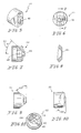
- a first flow divider 20 for use with nozzles 22, 122, 222 of the general type illustrated in Figs. 5-11, 12-15 or 16-19 includes an elongated rear region 24 with arcuate ends 26 and a forwardly extending impingement body region 27.
- the elongated rear region 24 is configured to fit with relatively close tolerance into a complementarily configured slot 28, 128, 228 provided therefor in the back side, or inside, 30, 130, 230 of a nozzle 22, 122, 222.
- the impingement body region 27 is generally part right circular cylindrical when viewed from the front. When viewed in side elevation, the two surfaces 32, 34 which guide the impinging streams of material to be sprayed are evident.
- Surfaces 32, 34 extend at equal angles of 25° to an axis 36 of flow divider 20 and to flat surfaces 38, 40 which bound the sector 42 of the right circular cylinder which forms the bulk of impingement body region 27, and along which the divided streams of material to be sprayed flow forward toward impingement at the junction 44 of surfaces 32, 34 in the orifice 45, 145, 245 of the nozzle 22, 122, 222.
- This junction 44 is bounded by chamfers 46, 48 which are provided at angles of, for example, 45°to the axis 36 of flow divider 20.
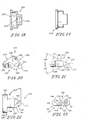
- a second flow divider 120 for use with nozzles 322 of the general type illustrated in Figs. 24-30 includes an elongated rear region 124 with arcuate ends 126 and a forwardly extending impingement body region 127.
- the elongated rear region 124 is configured to fit with relatively close tolerance into a complementarily configured slot 328 provided therefor in the back side, or inside, 330 of nozzle 322.
- the impingement body region 127 is generally part right circular cylindrical when viewed from the front. When viewed in side elevation, the two surfaces 132, 134 which guide the impinging streams of material to be sprayed are evident.
- Surfaces 132, 134 extend at equal angles of 25° to an axis 136 of flow divider 120 and to flat surfaces 138, 140 which bound the sector 142 of the right circular cylinder which forms the bulk of impingement body region 127, and along which the divided streams of material to be sprayed flow forward toward impingement at the junction 144 of surfaces 132, 134 in the orifice 345 of the nozzle 322.
- This junction 144 is bounded by somewhat frustoconically shaped surfaces 146, 148 which are provided at angles of, for example, 30°to the axis 136 of flow divider 120.
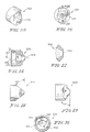
- a third flow divider 220 for use with nozzles 22, 122, 222 of the general type illustrated in Figs. 5-11, 12-15 or 16-19 includes an elongated rear region 224 with arcuate ends 226 and a forwardly extending impingement body region 227.
- the elongated rear region 224 is configured to fit with relatively close tolerance into a complementarily configured slot 28, 128, 228 provided therefor in the back side 30, 130, 230 of a nozzle 22, 122, 222.
- the impingement body region 227 is generally part right circular cylindrical when viewed from the front. When viewed in side elevation, the two surfaces 232, 234 which guide the impinging streams of material to be sprayed are evident.
- Surfaces 232, 234 extend at equal angles of 30° to an axis 236 of flow divider 220 and to flat surfaces 238, 240 which bound the sector 242 of the right circular cylinder which forms the bulk of impingement body region 227, and along which the divided streams of material to be sprayed flow forward toward impingement at the junction 244 of surfaces 232, 234 in the orifice 45, 145, 245 of the nozzle 22, 122, 222.
- This junction 244 is bounded by somewhat frustoconically shaped surfaces 246, 248 which are provided at angles of, for example, 45°to the axis 236 of flow divider 220.
- a fourth flow divider 320 for use with nozzles 422 of the general type illustrated in Figs. 39-45 includes an elongated rear region 324 with arcuate ends 326 and a forwardly extending impingement body region 327.
- the elongated rear region 324 is configured to fit with relatively close tolerance into a complementarily configured slot 428 provided therefor in the back side, or inside, 430 of nozzle 422.
- the impingement body region 327 is generally part right circular cylindrical when viewed from the front. When viewed in side elevation, the two surfaces 332, 334 which guide the impinging streams of material to be sprayed are evident.
- Surfaces 332, 334 extend at equal angles of 35° to an axis 336 of flow divider 320 and to flat surfaces 338, 340 which bound the sector 342 of the right circular cylinder which forms the bulk of impingement body region 327, and along which the divided streams of material to be sprayed flow forward toward impingement at the junction 344 of surfaces 332, 334 in the orifice 445 of the nozzle 422.
- the chamfers 46, 48, 146, 148, 246, 248 are replaced in this embodiment by arcuate features 346, 348 having radii of, for example, 3/32" (about 2.4 mm.).
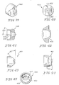
- a fifth flow divider 420 for use with nozzles 22, 122, 222 of the general type illustrated in Figs. 5-11, 12-15 or 16-19 includes an elongated rear region 424 with arcuate ends 426 and a forwardly extending impingement body region 427.
- the elongated rear region 424 is configured to fit with relatively close tolerance into a complementarily configured slot 28, 128, 228 provided therefor in the back side 30, 130, 230 of a nozzle 22, 122, 222.
- the impingement body region 427 is generally part right circular cylindrical when viewed from the front. When viewed in side elevation, the two surfaces 432, 434 which guide the impinging streams of material to be sprayed are evident.
- Surfaces 432, 434 extend at equal angles of 40° to an axis 436 of flow divider 420 and to flat surfaces 438, 440 which bound the sector 442 of the right circular cylinder which forms the bulk of impingement body region 427, and along which the divided streams of material to be sprayed flow forward toward impingement at the junction 444 of surfaces 432, 434 in the orifice 45, 145, 245 of the nozzle 22, 122, 222.
- This junction 444 is bounded by somewhat frustoconically shaped surfaces 446, 448 which are provided at angles of, for example, 45°to the axis 436 of flow divider 420.
- the nozzles 22, 122, 222, 322, 422 illustrated in Figs. 5-11, 12-15, 16-19, 24-30 and 39-45 include either internal or external threads, flanges for engagement by nuts (450 illustrated in broken lines in Fig. 82), or the like, all well known in the art, for attachment to the front ends of guns, for the supply to the nozzles 22, 122, 222, 322, 422 of high pressure flows of the material to be dispensed through nozzles 22, 122, 222, 322, 422.
- the material to be sprayed is provided to the back sides 30, 130, 230, 330 of all of nozzles 22, 122, 222, 322, 422.
- the material flows forward, it is divided into two streams by the flow divider 20, 120, 220, 320, 420.
- the separate flows then reconverge and impinge upon each other as they flow forward, in the region of the discharge orifice 45, 145, 245, 345, 445 of the nozzle 22, 122, 222, 322, 422.
- a sixth flow divider 520 for use with nozzle bodies 521 of the general type illustrated in Figs. 62-65 and nozzles 522, 622 of the general type illustrated in Figs. 66-69 or 70-73 includes a screw threaded rear region 524 and a forwardly extending impingement body region 527.
- the screw threaded rear region 524 is configured to screw into a complementarily threaded region 523 of nozzle body 521.
- the impingement body region 527 is generally part right circular cylindrical when viewed from the front. When viewed in side elevation, the two surfaces 532, 534 which guide the impinging streams of material to be sprayed are evident.
- Surfaces 532, 534 extend at equal angles of 30° to an axis 536 of flow divider 520 and to flat surfaces 538, 540 which bound the sector 542 of the right circular cylinder which forms the bulk of impingement body region 527, and along which the divided streams of material to be sprayed flow forward toward impingement at the junction 544 of surfaces 532, 534 in the orifice 545, 645 of the nozzle 522, 622.
- This junction 544 is bounded by tapered, generally frustoconical surfaces 546, 548 which extend at angles of, for example, 32.5°to the axis 536 of flow divider 520, and terminate at a tip 550 which is at least partly right circular cylindrical when viewed from the front and complementarily sized to fit within orifice 545, 645.
- a seventh flow divider 620 for use with nozzle bodies 521 of the general type illustrated in Figs. 62-65 and nozzles 522, 622 of the general type illustrated in Figs. 66-69 or 70-73 includes a screw threaded rear region 624 and a forwardly extending impingement body region 627.
- the screw threaded rear region 624 is configured to screw into complementarily threaded region 523 of nozzle body 521.
- the impingement body region 627 is generally part right circular cylindrical when viewed from the front. When viewed in side elevation, the two surfaces 632, 634 which guide the impinging streams of material to be sprayed are evident.
- Surfaces 632, 634 extend at equal angles of 40° to an axis 636 of flow divider 620.
- Flat surfaces 638, 640 bound the sector 642 of the right circular cylinder which forms the bulk of impingement body region 627.
- the divided streams of material to be sprayed flow forward along surfaces 638, 640 toward impingement at the junction 644 of surfaces 632, 634 in the orifice of the nozzle 522, 622.
- This junction 644 is bounded by tapered, generally frustoconical surfaces 646, 648 which are provided at angles of, for example, 30°to the axis 636 of flow divider 620.
- an eighth flow divider 720 for use with nozzle bodies 521 of the general type illustrated in Figs. 62-65 and nozzles 522, 622 of the general type illustrated in Figs. 66-69 or 70-73 includes a screw threaded rear region 724 and a forwardly extending impingement body region 727.
- the screw threaded rear region 724 is configured to screw into complementarily threaded region 523 of nozzle body 521.
- the impingement body region 727 is generally part right circular cylindrical when viewed from the front. When viewed in side elevation, the two surfaces 732, 734 which guide the impinging streams of material to be sprayed are evident.
- Surfaces 732, 734 extend at equal angles of 40° to an axis 736 of flow divider 720 and to flat surfaces 738, 740 which bound the sector 742 of the right circular cylinder which forms the bulk of impingement body region 727, and along which the divided streams of material to be sprayed flow forward toward impingement at the junction 744 of surfaces 732, 734 in the orifice of the nozzle 522, 622.
- This junction 744 is bounded by tapered, generally frustoconical surfaces 746, 748 which extend at angles of, for example, 42.5°to the axis 736 of flow divider 720, and terminate at a tip 750 which is at least partly right circular cylindrical when viewed from the front and complementarily sized to fit within orifice 545, 645.
- Nozzle body 521 also includes screw threaded region 525.
- Nozzles 522, 622 include complementarily threaded regions 527, 627 for receiving the threads of screw threaded region 525 of nozzle body 521 to assemble the nozzle.
- the material to be sprayed is provided to the back sides 530, 630 of nozzles 522, 622.
- a ninth flow divider 820 for use with nozzles 22, 122, 222 of the general type illustrated in Figs. 5-11, 12-15 or 16-19 includes an elongated rear region 824 with arcuate ends 826 and a forwardly extending impingement body region 827.
- the elongated rear region 824 is configured to fit with relatively close tolerance into a complementarily configured slot 28, 128, 228 provided therefor in the back side 30, 130, 230 of a nozzle 22, 122, 222.
- the impingement body region 827 is generally part right circular cylindrical when viewed from the front. When viewed in side elevation, the two surfaces 832, 834 which guide the impinging streams of material to be sprayed are evident.
- Surfaces 832, 834 extend at equal angles of 35° to an axis 836 of flow divider 820 and to flat surfaces 838, 840 which bound the sector 842 of the right circular cylinder which forms the bulk of impingement body region 827, and along which the divided streams of material to be sprayed flow forward toward impingement at the junction 844 of surfaces 832, 834 in the orifice 45, 145, 245 of the nozzle 22, 122, 222.
- This junction 844 is bounded by somewhat frustoconically shaped surfaces 846, 848 which are provided at angles of, for example, 45°to the axis 836 of flow divider 820.
- a tenth flow divider 920 for use with nozzles 922, 1022 of the general type illustrated in Figs. 82-85 or 86-91, respectively, includes an elongated rear region 924 with arcuate ends 926 and a forwardly extending impingement body region 927.
- the elongated rear region 924 is configured to fit with relatively close tolerance into a complementarily configured slot 928, 1028, respectively, provided therefor in the back side 930, 1030, respectively, of nozzle 922, 1022.
- the impingement body region 927 is generally part right circular cylindrical when viewed from the front.
- the nozzles 922, 1022 illustrated in Figs. 82-85 and 86-91 include either internal or external threads, flanges for engagement by nuts, or the like, all well known in the art, for attachment to the front ends of guns for the supply to the nozzles 922, 1022 of high pressure flows of the material to be dispensed through nozzles 922, 1022.
- the material to be sprayed is provided to the back sides 930, 1030 of nozzles 922, 1022, respectively.
- the separate flows then reconverge and impinge upon each other as they flow forward, in the region of the discharge orifice 945, 1045 of the nozzle 922, 1022, respectively.
- the nozzles 22, 122, 222, 322, 422, 922, 1022 can be constructed from any suitable materials.
- the bodies of these devices can be constructed from aluminum, stainless steel, or the like, treated to reduce the effects of wear or with wear inserts of, for example, tool steel or tungsten carbide, in areas subject to greater wear, such as surfaces 32, 34, 132, 134, 232, 234, 332, 334, 432, 434, 532, 534, 632, 634, 732, 734, 832, 834, 932, 934, and around orifices 45, 145, 245, 345, 445, 545, 645, 945, 1045.
Landscapes
- Nozzles (AREA)
Abstract
An apparatus for dispensing a fluid includes a nozzle (22) defining an
orifice in a front face of the nozzle (22). The material is discharged through the orifice.
The nozzle (22) includes a flow divider (20) cooperating to separate a supply of the material
into two streams. The flow divider includes two surfaces (32,34) which intersect not further
forward in the nozzle (22) than the front face.
Description
This invention relates to devices for the spraying of fluids. It is
disclosed in the context of devices for the spraying of fluid resins, monomers,
oligomers, or the like. As used here, oligomer means a polymer made up of a few
monomer units so that it remains fluid However, it may be useful in other
applications as well.
The application of gel coats or other pigmented resins, for example, in
the production of finish surfaces on tubs, shower stalls, watercraft hulls, and many
other articles, typically requires lower flow rates of these materials than those
required to build up the underlying structural layers of such articles. For example,
external impingement tips designed for such flow rates typically have discharge
orifice diameters in the range of about .018" - .023" (about .46 mm. - .58 mm.).
These orifices must be disposed in the plane of the spray with tolerances typically on the order of about .001" - .002" (about .025 mm. - .05 mm.) in order to develop a satisfactory spray pattern.
These orifices must be disposed in the plane of the spray with tolerances typically on the order of about .001" - .002" (about .025 mm. - .05 mm.) in order to develop a satisfactory spray pattern.
Several types of spray nozzles which use single orifice, undivided
flows of material to produce relatively flat, "fan-shaped" sprays are known. Typically
those nozzles require relatively high pressure delivery of the material to be sprayed in
order to produce their characteristic flat, fan-shaped spray patterns. The use of high
pressure, however, results in quite fine atomization and attendant overspray, atomized
particles that do not reach the article to be coated, and thus are wasted. Additionally,
fine atomization results in the release of considerable amounts of the carriers, such as
volatile organic compounds, or VOCs, for the sprayed materials, such as liquid paints
and resins. The release of VOCs raises workplace safety and environmental concerns,
and thus is to be avoided wherever possible.
In an effort to avoid the use of high pressure in spraying of materials,
the use of external impingement nozzles has been proposed. There are, for example,
the systems described in U. S. Patents 6,113,013 and 6,322,008 and the references
cited in these two patents. No representation is intended by this listing that this is a
complete listing of all pertinent prior art, or that a thorough search of all pertinent
prior art has been conducted, or that no better prior art exists. Nor should any such
representation be inferred.
In systems of the type described in these two patents, two separate
coarse jets of the material to be sprayed are produced. These two jets are angled by
the spray apparatus so that the jets impinge upon each other a distance in front of the
spray apparatus. A more finely divided, fan-shaped spray of the material results
beyond the point at which the two jets impinge upon each other. This spray pattern
typically has heavy edge margins, making it less than completely satisfactory for
applications requiring relatively uniform sprayed particle size distribution, without the
application of auxiliary jets of air to the heavy-edged fan-shaped spray pattern.
Other proposals exist for the production of sprays. These include
nozzles which produce non-intersecting jets of material, somewhat like the spray
produced by a showerhead. Showerhead-type nozzles typically produce "striped"
spray patterns. These spray patterns also often suffer from too-broad distribution of
sprayed particle sizes to produce the results sometimes required in such applications.
According to an aspect of the invention, an apparatus for dispensing a
fluid includes a nozzle defining an orifice in a front face of the nozzle, through which
orifice the material is discharged. The nozzle includes a flow divider cooperating to
separate a supply of the material into two streams. The flow divider includes two
surfaces which intersect not further forward in the nozzle than the front face.
Illustratively according to this aspect of the invention, the two surfaces
make substantially equal angles adjacent the orifice to a longitudinal axis of the
nozzle.
Further illustratively according to this aspect of the invention, the
nozzle includes a first feature and the flow divider is formed as a separate component
including a second feature. The first and second features cooperate to orient the
intersection of the two surfaces with respect to the orifice.
Further illustratively according to this aspect of the invention, the
nozzle includes a first feature and the flow divider includes a second feature
cooperating with the first feature to orient the intersection of the two surfaces with
respect to the orifice.
Additionally illustratively according to this aspect of the invention, the
first feature includes a relief formed in a back side of the front face, and the second
feature includes a region of the flow divider for orientation in the relief.
Illustratively according to this aspect of the invention, the angles are
between 20 and 60 degrees. Angles less than 20 degrees and greater than 60 degrees
are also useful.
Futher illustratively according to this aspect of the invention, the
angles are between 25 and 40 degrees. Angles less than 25 degrees and greater than
40 degrees are also useful.
Illustratively according to this aspect of the invention, the orifice is
generally circular transverse to an axis of the nozzle.
Alternatively illustratively according to this aspect of the invention, the
orifice is generally somewhat oval shaped or cat's eye shaped transverse to an axis of
the nozzle. Other orifice shapes are also useful, for example, diamond shaped,
elliptical, square, and so on.
Illustratively according to this aspect of the invention, the two surfaces
include two flat surfaces. The surfaces may also be concave, convex or irregular.
According to another aspect of the invention, a method of dispensing a
fluid includes impinging separate streams of the fluid against each other and
substantially simultaneously ejecting the reunited stream through an orifice.
Illustratively according to this aspect of the invention, the method
further includes dividing a flow of the fluid into the separate streams using a flow
divider. Impinging the streams against each other includes impinging the streams
against each other at a downstream end of the flow divider.
Illustratively according to this aspect of the invention, impinging the
streams against each other at a downstream end of the flow divider includes providing
on the flow divider separate surfaces across which the separate streams flow
downstream from a point at which the flow divider divides the fluid into separate
streams. The separate surfaces intersect each other no further downstream in the flow
of the fluid than the orifice.
According to another aspect of the invention, an article is made by
impinging separate streams of a fluid against each other and substantially
simultaneously ejecting the reunited stream formed from the impinging streams
through an orifice.
Illustratively according to this aspect of the invention, the article is
made by dividing a curable fluid into the separate streams, impinging the streams
against each other, substantially simultaneously ejecting the reunited streams through
the orifice onto a surface having a complementary shape to a shape of the article,
permitting the fluid to cure on the complementarily shaped surface, and removing the
article from the surface.
Further illustratively according to this aspect of the invention, the
article is made by dividing the fluid into separate streams using a flow divider, and
impinging the streams against each other at a downstream end of the flow divider.
Additionally illustratively according to this aspect of the invention, the
article is made by providing on the flow divider separate surfaces across which the
separate streams flow downstream from a point at which the flow divider divides the
fluid into separate streams. The separate surfaces intersect each other no further
downstream in the flow of the fluid than the orifice.
According to yet another aspect of the invention, apparatus for
dispensing a fluid includes means for dividing a flow of fluid into separate streams,
means for impinging the separate streams against each other, and means for
substantially simultaneously ejecting the reunited stream through an orifice.
Illustratively according to this aspect of the invention, the means for
dividing the fluid into separate streams includes a flow divider, and the means for
impinging the streams against each other includes impingement means at a
downstream end of the flow divider.
Illustratively according to this aspect of the invention, the
impingement means includes separate surfaces which intersect each other no further
downstream in the flow of the fluid than the orifice.
The invention may best be understood by referring to the following
detailed description and accompanying drawings which illustrate the invention. In the
drawings:
A device constructed according to the present invention includes a
flow divider and an outer nozzle body. The flow divider splits a fluid stream (8
illustrated diagrammatically in Fig. 82), usually from the body of a device sometimes
referred to as a gun (10 illustrated fragmentarily in Fig. 82), into two distinct flows,
then recombines them at the outer nozzle body's orifice at a prescribed angle to form
a flat sheet of fluid, forming a coarse, flat spray pattern (12 in Fig. 82) for spraying
onto, for example, a surface (14 illustrated fragmentarily in Fig. 82) of a mold or the
like in the process of forming an article (16 illustrated fragmentarily in Fig. 82)
having a surface configured complementarily to the surface 14. The invention thus
provides a simple and inexpensive method to provide a low-pressure, coarse, flat
spray pattern with relatively narrow distribution of sprayed particle sizes. This is
accomplished with a relatively small number of relatively easily manufactured parts.
Instead of manufacturing a large number of discrete nozzles with distinct orifice and
angle combinations, the desired spray angle is provided by the included angle of the
surfaces of the flow divider. The flow divider is constructed from a blank with flats
milled, ground or otherwise provided, with an appropriate included angle. The outer
nozzle body provides'the orifice size. A larger, single orifice, which may be, for
example, generally circular, generally oval, generally cat's eye shaped, or slot shaped,
is provided in the outer nozzle body, so alignment is maintained.
Referring now to Figs. 1-4, a first flow divider 20 for use with nozzles
22, 122, 222 of the general type illustrated in Figs. 5-11, 12-15 or 16-19 includes an
elongated rear region 24 with arcuate ends 26 and a forwardly extending impingement
body region 27. The elongated rear region 24 is configured to fit with relatively close
tolerance into a complementarily configured slot 28, 128, 228 provided therefor in the
back side, or inside, 30, 130, 230 of a nozzle 22, 122, 222. The impingement body
region 27 is generally part right circular cylindrical when viewed from the front.
When viewed in side elevation, the two surfaces 32, 34 which guide the impinging
streams of material to be sprayed are evident. Surfaces 32, 34 extend at equal angles
of 25° to an axis 36 of flow divider 20 and to flat surfaces 38, 40 which bound the
sector 42 of the right circular cylinder which forms the bulk of impingement body
region 27, and along which the divided streams of material to be sprayed flow
forward toward impingement at the junction 44 of surfaces 32, 34 in the orifice 45,
145, 245 of the nozzle 22, 122, 222. This junction 44 is bounded by chamfers 46, 48
which are provided at angles of, for example, 45°to the axis 36 of flow divider 20.
Referring now to Figs. 20-23, a second flow divider 120 for use with
nozzles 322 of the general type illustrated in Figs. 24-30 includes an elongated rear
region 124 with arcuate ends 126 and a forwardly extending impingement body
region 127. The elongated rear region 124 is configured to fit with relatively close
tolerance into a complementarily configured slot 328 provided therefor in the back
side, or inside, 330 of nozzle 322. The impingement body region 127 is generally
part right circular cylindrical when viewed from the front. When viewed in side
elevation, the two surfaces 132, 134 which guide the impinging streams of material to
be sprayed are evident. Surfaces 132, 134 extend at equal angles of 25° to an axis 136
of flow divider 120 and to flat surfaces 138, 140 which bound the sector 142 of the
right circular cylinder which forms the bulk of impingement body region 127, and
along which the divided streams of material to be sprayed flow forward toward
impingement at the junction 144 of surfaces 132, 134 in the orifice 345 of the nozzle
322. This junction 144 is bounded by somewhat frustoconically shaped surfaces 146,
148 which are provided at angles of, for example, 30°to the axis 136 of flow divider
120.
Referring now to Figs. 31-34, a third flow divider 220 for use with
nozzles 22, 122, 222 of the general type illustrated in Figs. 5-11, 12-15 or 16-19
includes an elongated rear region 224 with arcuate ends 226 and a forwardly
extending impingement body region 227. The elongated rear region 224 is configured
to fit with relatively close tolerance into a complementarily configured slot 28, 128,
228 provided therefor in the back side 30, 130, 230 of a nozzle 22, 122, 222. The
impingement body region 227 is generally part right circular cylindrical when viewed
from the front. When viewed in side elevation, the two surfaces 232, 234 which
guide the impinging streams of material to be sprayed are evident. Surfaces 232, 234
extend at equal angles of 30° to an axis 236 of flow divider 220 and to flat surfaces
238, 240 which bound the sector 242 of the right circular cylinder which forms the
bulk of impingement body region 227, and along which the divided streams of
material to be sprayed flow forward toward impingement at the junction 244 of
surfaces 232, 234 in the orifice 45, 145, 245 of the nozzle 22, 122, 222. This junction
244 is bounded by somewhat frustoconically shaped surfaces 246, 248 which are
provided at angles of, for example, 45°to the axis 236 of flow divider 220.
Referring now to Figs. 35-38, a fourth flow divider 320 for use with
nozzles 422 of the general type illustrated in Figs. 39-45 includes an elongated rear
region 324 with arcuate ends 326 and a forwardly extending impingement body
region 327. The elongated rear region 324 is configured to fit with relatively close
tolerance into a complementarily configured slot 428 provided therefor in the back
side, or inside, 430 of nozzle 422. The impingement body region 327 is generally
part right circular cylindrical when viewed from the front. When viewed in side
elevation, the two surfaces 332, 334 which guide the impinging streams of material to
be sprayed are evident. Surfaces 332, 334 extend at equal angles of 35° to an axis 336
of flow divider 320 and to flat surfaces 338, 340 which bound the sector 342 of the
right circular cylinder which forms the bulk of impingement body region 327, and
along which the divided streams of material to be sprayed flow forward toward
impingement at the junction 344 of surfaces 332, 334 in the orifice 445 of the nozzle
422. The chamfers 46, 48, 146, 148, 246, 248 are replaced in this embodiment by
arcuate features 346, 348 having radii of, for example, 3/32" (about 2.4 mm.).
Referring now to Figs. 46-49, a fifth flow divider 420 for use with
nozzles 22, 122, 222 of the general type illustrated in Figs. 5-11, 12-15 or 16-19
includes an elongated rear region 424 with arcuate ends 426 and a forwardly
extending impingement body region 427. The elongated rear region 424 is configured
to fit with relatively close tolerance into a complementarily configured slot 28, 128,
228 provided therefor in the back side 30, 130, 230 of a nozzle 22, 122, 222. The
impingement body region 427 is generally part right circular cylindrical when viewed
from the front. When viewed in side elevation, the two surfaces 432, 434 which
guide the impinging streams of material to be sprayed are evident. Surfaces 432, 434
extend at equal angles of 40° to an axis 436 of flow divider 420 and to flat surfaces
438, 440 which bound the sector 442 of the right circular cylinder which forms the
bulk of impingement body region 427, and along which the divided streams of
material to be sprayed flow forward toward impingement at the junction 444 of
surfaces 432, 434 in the orifice 45, 145, 245 of the nozzle 22, 122, 222. This junction
444 is bounded by somewhat frustoconically shaped surfaces 446, 448 which are
provided at angles of, for example, 45°to the axis 436 of flow divider 420.
The nozzles 22, 122, 222, 322, 422 illustrated in Figs. 5-11, 12-15, 16-19,
24-30 and 39-45 include either internal or external threads, flanges for
engagement by nuts (450 illustrated in broken lines in Fig. 82), or the like, all well
known in the art, for attachment to the front ends of guns, for the supply to the
nozzles 22, 122, 222, 322, 422 of high pressure flows of the material to be dispensed
through nozzles 22, 122, 222, 322, 422. The material to be sprayed is provided to the
back sides 30, 130, 230, 330 of all of nozzles 22, 122, 222, 322, 422. As the material
flows forward, it is divided into two streams by the flow divider 20, 120, 220, 320,
420. The separate flows then reconverge and impinge upon each other as they flow
forward, in the region of the discharge orifice 45, 145, 245, 345, 445 of the nozzle 22,
122, 222, 322, 422.
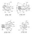
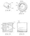
Referring now to Figs. 50-53, a sixth flow divider 520 for use with
nozzle bodies 521 of the general type illustrated in Figs. 62-65 and nozzles 522, 622
of the general type illustrated in Figs. 66-69 or 70-73 includes a screw threaded rear
region 524 and a forwardly extending impingement body region 527. The screw
threaded rear region 524 is configured to screw into a complementarily threaded
region 523 of nozzle body 521. The impingement body region 527 is generally part
right circular cylindrical when viewed from the front. When viewed in side elevation,
the two surfaces 532, 534 which guide the impinging streams of material to be
sprayed are evident. Surfaces 532, 534 extend at equal angles of 30° to an axis 536 of
flow divider 520 and to flat surfaces 538, 540 which bound the sector 542 of the right
circular cylinder which forms the bulk of impingement body region 527, and along
which the divided streams of material to be sprayed flow forward toward
impingement at the junction 544 of surfaces 532, 534 in the orifice 545, 645 of the
nozzle 522, 622. This junction 544 is bounded by tapered, generally frustoconical
surfaces 546, 548 which extend at angles of, for example, 32.5°to the axis 536 of flow
divider 520, and terminate at a tip 550 which is at least partly right circular cylindrical
when viewed from the front and complementarily sized to fit within orifice 545, 645.
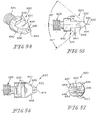
Referring now to Figs. 54-57, a seventh flow divider 620 for use with
nozzle bodies 521 of the general type illustrated in Figs. 62-65 and nozzles 522, 622
of the general type illustrated in Figs. 66-69 or 70-73 includes a screw threaded rear
region 624 and a forwardly extending impingement body region 627. The screw
threaded rear region 624 is configured to screw into complementarily threaded region
523 of nozzle body 521. The impingement body region 627 is generally part right
circular cylindrical when viewed from the front. When viewed in side elevation, the
two surfaces 632, 634 which guide the impinging streams of material to be sprayed
are evident. Surfaces 632, 634 extend at equal angles of 40° to an axis 636 of flow
divider 620. Flat surfaces 638, 640 bound the sector 642 of the right circular cylinder
which forms the bulk of impingement body region 627. The divided streams of
material to be sprayed flow forward along surfaces 638, 640 toward impingement at
the junction 644 of surfaces 632, 634 in the orifice of the nozzle 522, 622. This
junction 644 is bounded by tapered, generally frustoconical surfaces 646, 648 which
are provided at angles of, for example, 30°to the axis 636 of flow divider 620.
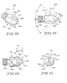
Referring now to Figs. 58-61, an eighth flow divider 720 for use with
nozzle bodies 521 of the general type illustrated in Figs. 62-65 and nozzles 522, 622
of the general type illustrated in Figs. 66-69 or 70-73 includes a screw threaded rear
region 724 and a forwardly extending impingement body region 727. The screw
threaded rear region 724 is configured to screw into complementarily threaded region
523 of nozzle body 521. The impingement body region 727 is generally part right
circular cylindrical when viewed from the front. When viewed in side elevation, the
two surfaces 732, 734 which guide the impinging streams of material to be sprayed
are evident. Surfaces 732, 734 extend at equal angles of 40° to an axis 736 of flow
divider 720 and to flat surfaces 738, 740 which bound the sector 742 of the right
circular cylinder which forms the bulk of impingement body region 727, and along
which the divided streams of material to be sprayed flow forward toward
impingement at the junction 744 of surfaces 732, 734 in the orifice of the nozzle 522,
622. This junction 744 is bounded by tapered, generally frustoconical surfaces 746,
748 which extend at angles of, for example, 42.5°to the axis 736 of flow divider 720,
and terminate at a tip 750 which is at least partly right circular cylindrical when
viewed from the front and complementarily sized to fit within orifice 545, 645.
Referring now to Figs. 74-77, a ninth flow divider 820 for use with
nozzles 22, 122, 222 of the general type illustrated in Figs. 5-11, 12-15 or 16-19
includes an elongated rear region 824 with arcuate ends 826 and a forwardly
extending impingement body region 827. The elongated rear region 824 is configured
to fit with relatively close tolerance into a complementarily configured slot 28, 128,
228 provided therefor in the back side 30, 130, 230 of a nozzle 22, 122, 222. The
impingement body region 827 is generally part right circular cylindrical when viewed
from the front. When viewed in side elevation, the two surfaces 832, 834 which
guide the impinging streams of material to be sprayed are evident. Surfaces 832, 834
extend at equal angles of 35° to an axis 836 of flow divider 820 and to flat surfaces
838, 840 which bound the sector 842 of the right circular cylinder which forms the
bulk of impingement body region 827, and along which the divided streams of
material to be sprayed flow forward toward impingement at the junction 844 of
surfaces 832, 834 in the orifice 45, 145, 245 of the nozzle 22, 122, 222. This junction
844 is bounded by somewhat frustoconically shaped surfaces 846, 848 which are
provided at angles of, for example, 45°to the axis 836 of flow divider 820.
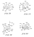
Referring now to Figs. 78-81, a tenth flow divider 920 for use with
nozzles 922, 1022 of the general type illustrated in Figs. 82-85 or 86-91, respectively,
includes an elongated rear region 924 with arcuate ends 926 and a forwardly
extending impingement body region 927. The elongated rear region 924 is configured
to fit with relatively close tolerance into a complementarily configured slot 928, 1028,
respectively, provided therefor in the back side 930, 1030, respectively, of nozzle 922,
1022. The impingement body region 927 is generally part right circular cylindrical
when viewed from the front. When viewed in side elevation, the two surfaces 932,
934 which guide the impinging streams of material to be sprayed are evident.
Surfaces 932, 934 extend at equal angles of 30° to an axis 936 of flow divider 920 and
to flat surfaces 938, 940 which bound the sector 942 of the right circular cylinder
which forms the bulk of impingement body region 927, and along which the divided
streams of material to be sprayed flow forward toward impingement at the junction
944 of surfaces 932, 934 in the orifice 945 or 1045 of the nozzle 922 or 1022,
respectively. This junction 944 is bounded by somewhat frustoconically shaped
surfaces 946, 948 which are provided at angles of, for example, 45°to the axis 936 of
flow divider 920.
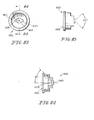
The nozzles 922, 1022 illustrated in Figs. 82-85 and 86-91 include
either internal or external threads, flanges for engagement by nuts, or the like, all well
known in the art, for attachment to the front ends of guns for the supply to the nozzles
922, 1022 of high pressure flows of the material to be dispensed through nozzles 922,
1022. The material to be sprayed is provided to the back sides 930, 1030 of nozzles
922, 1022, respectively. As the material flows forward, it is divided into two streams
by the flow divider, for example, flow divider 920. The separate flows then
reconverge and impinge upon each other as they flow forward, in the region of the
discharge orifice 945, 1045 of the nozzle 922, 1022, respectively.
The nozzles 22, 122, 222, 322, 422, 922, 1022 can be constructed from
any suitable materials. For example, the bodies of these devices can be constructed
from aluminum, stainless steel, or the like, treated to reduce the effects of wear or
with wear inserts of, for example, tool steel or tungsten carbide, in areas subject to
greater wear, such as surfaces 32, 34, 132, 134, 232, 234, 332, 334, 432, 434, 532,
534, 632, 634, 732, 734, 832, 834, 932, 934, and around orifices 45, 145, 245, 345,
445, 545, 645, 945, 1045.
Claims (19)
- Apparatus for dispensing a fluid, the apparatus including a nozzle defining an orifice in a front face of the nozzle, through which orifice the material is discharged, the nozzle including a flow divider cooperating to separate a supply of the material into two streams, the flow divider including two surfaces which intersect not further forward in the nozzle than the front face.
- The apparatus of claim 1 wherein the two surfaces include two flat surfaces.
- The apparatus of claim 1 or 2 wherein adjacent the orifice the two surfaces make substantially equal angles to a longitudinal axis of the nozzle.
- The apparatus of at least one of the preceding claims wherein the nozzle includes a first feature and the flow divider is formed as a separate component including a second feature cooperating with the first feature to orient the intersection of the two surfaces with respect to the orifice.
- The apparatus of claim 4 wherein the first feature includes a relief formed in a back side of the front face, and the second feature includes a region of the flow divider for orientation in the relief.
- The apparatus of at least one of claims 3 to 5 wherein the angles are between 20 and 60 degrees.
- The apparatus of claim 6 wherein the angles are between 25 and 40 degrees.
- The apparatus of at least one of the preceding claims wherein the orifice is generally circular transverse to an axis of the nozzle.
- The apparatus of at least one of the preceding claims wherein the orifice is generally cat's eye shaped transverse to an axis of the nozzle.
- A method of dispensing a fluid, the method including impinging separate streams of the fluid against each other, and substantially simultaneously ejecting the reunited stream through an orifice.
- The method of claim 10 further including dividing a flow of the fluid into the separate streams using a flow divider, impinging the streams against each other including impinging the streams against each other at a downstream end of the flow divider.
- The method of claim 11 wherein impinging the streams against each other at a downstream end of the flow divider includes providing on the flow divider separate surfaces across which the separate streams flow downstream from a point at which the flow divider divides the fluid into separate streams, the separate surfaces intersecting each other no further downstream in the flow of the fluid than the orifice.
- An article made by impinging separate streams of a fluid against each other, and substantially simultaneously ejecting the reunited stream formed from the impinging streams through an orifice.
- The article of claim 13 made by dividing a curable fluid into the separate streams, impinging the streams against each other, substantially simultaneously ejecting the reunited streams through an orifice onto a surface having a complementary shape to a shape of the article, permitting the fluid to cure on the complementarily shaped surface, and removing the article from the surface.
- The article of claim 13 or 14 made by dividing the fluid into separate streams using a flow divider, and impinging the streams against each other at a downstream end of the flow divider.
- The article of claim 15 made by providing on the flow divider separate surfaces across which the separate streams flow downstream from a point at which the flow divider divides the fluid into separate streams, the separate surfaces intersecting each other no further downstream in the flow of the fluid than the orifice.
- Apparatus for dispensing a fluid, the apparatus including means for dividing a flow of fluid into separate streams, means for impinging the separate streams against each other, and means for substantially simultaneously ejecting the reunited stream through an orifice.
- The apparatus of claim 17 wherein the means for dividing the fluid into separate streams includes a flow divider, and the means for impinging the streams against each other includes impingement means at a downstream end of the flow divider.
- The method of claim 18 wherein the impingement means includes separate surfaces which intersect each other no further downstream in the flow of the fluid than the orifice.
Applications Claiming Priority (4)
| Application Number | Priority Date | Filing Date | Title |
|---|---|---|---|
| US33861101P | 2001-12-03 | 2001-12-03 | |
| US338611P | 2001-12-03 | ||
| US176194 | 2002-06-20 | ||
| US10/176,194 US20030102337A1 (en) | 2001-12-03 | 2002-06-20 | Internal impingement nozzle |
Publications (1)
| Publication Number | Publication Date |
|---|---|
| EP1316363A1 true EP1316363A1 (en) | 2003-06-04 |
Family
ID=26871979
Family Applications (1)
| Application Number | Title | Priority Date | Filing Date |
|---|---|---|---|
| EP02023138A Withdrawn EP1316363A1 (en) | 2001-12-03 | 2002-10-15 | Internal impingement nozzle |
Country Status (3)
| Country | Link |
|---|---|
| US (1) | US20030102337A1 (en) |
| EP (1) | EP1316363A1 (en) |
| CN (1) | CN1454716A (en) |
Cited By (1)
| Publication number | Priority date | Publication date | Assignee | Title |
|---|---|---|---|---|
| US5879953A (en) * | 1988-02-20 | 1999-03-09 | Hoechst Aktiengesellschaft | Special chemiluminescent acridine derivatives and the use thereof in luminescence immunoassays |
Families Citing this family (2)
| Publication number | Priority date | Publication date | Assignee | Title |
|---|---|---|---|---|
| EP1896188B1 (en) * | 2005-06-29 | 2010-08-18 | Boehringer Ingelheim International GmbH | Method and device for atomising liquid |
| US12240005B2 (en) * | 2018-05-07 | 2025-03-04 | Phoenix Industries Pty Ltd | Spray head |
Citations (4)
| Publication number | Priority date | Publication date | Assignee | Title |
|---|---|---|---|---|
| US4141507A (en) * | 1976-05-03 | 1979-02-27 | Dietz Armaturen Gmbh | Liquid discharge nozzle with flow divider |
| US5524660A (en) * | 1995-06-28 | 1996-06-11 | Basf Corporation | Plate-type spray nozzle and method of use |
| GB2296671A (en) * | 1994-11-23 | 1996-07-10 | Lancashire Environmental Servi | Waste treatment and spray nozzle |
| FR2766108A1 (en) * | 1997-07-17 | 1999-01-22 | France Etat | DEVICE FOR GENERATING A DIPHASIC FLUID |
Family Cites Families (3)
| Publication number | Priority date | Publication date | Assignee | Title |
|---|---|---|---|---|
| US1230982A (en) * | 1916-10-09 | 1917-06-26 | Ernest J Lloyd | Oil-burner. |
| US3568933A (en) * | 1969-03-05 | 1971-03-09 | Oxford Ind Group | Spray nozzles |
| US5890661A (en) * | 1996-11-27 | 1999-04-06 | Par-Way Group | Colliding stream spray dispensing system with a moldable nozzle |
-
2002
- 2002-06-20 US US10/176,194 patent/US20030102337A1/en not_active Abandoned
- 2002-10-15 EP EP02023138A patent/EP1316363A1/en not_active Withdrawn
- 2002-12-03 CN CN02153697A patent/CN1454716A/en active Pending
Patent Citations (4)
| Publication number | Priority date | Publication date | Assignee | Title |
|---|---|---|---|---|
| US4141507A (en) * | 1976-05-03 | 1979-02-27 | Dietz Armaturen Gmbh | Liquid discharge nozzle with flow divider |
| GB2296671A (en) * | 1994-11-23 | 1996-07-10 | Lancashire Environmental Servi | Waste treatment and spray nozzle |
| US5524660A (en) * | 1995-06-28 | 1996-06-11 | Basf Corporation | Plate-type spray nozzle and method of use |
| FR2766108A1 (en) * | 1997-07-17 | 1999-01-22 | France Etat | DEVICE FOR GENERATING A DIPHASIC FLUID |
Cited By (1)
| Publication number | Priority date | Publication date | Assignee | Title |
|---|---|---|---|---|
| US5879953A (en) * | 1988-02-20 | 1999-03-09 | Hoechst Aktiengesellschaft | Special chemiluminescent acridine derivatives and the use thereof in luminescence immunoassays |
Also Published As
| Publication number | Publication date |
|---|---|
| CN1454716A (en) | 2003-11-12 |
| US20030102337A1 (en) | 2003-06-05 |
Similar Documents
| Publication | Publication Date | Title |
|---|---|---|
| EP1108476B1 (en) | Low-pressure atomizing spray gun | |
| CN111318387B (en) | Low pressure spray head structure | |
| EP1447139B1 (en) | Automatic air-assisted manifold mounted gun | |
| CA2570070C (en) | Fluid atomizing system and method | |
| US20160318056A1 (en) | SPRAY EDGER DEVICES suitable for use with MATERIAL APPLICATION APPARATUS | |
| CN115210000B (en) | Spray Nozzle | |
| KR20170016937A (en) | Nozzle assembly with external baffles | |
| US20140230726A1 (en) | Spray coating system and method | |
| US20130032644A1 (en) | External mix air atomizing spray nozzle assembly | |
| US6918546B2 (en) | Reversible spray head | |
| CA1132634A (en) | Self-cleaning spray nozzle | |
| EP1316364A1 (en) | Internal impingement nozzle | |
| US20030102337A1 (en) | Internal impingement nozzle | |
| US6021962A (en) | Air assisted resin spray nozzle | |
| US12582999B2 (en) | Two-fluid nozzle with an arcuate opening | |
| CN113019739A (en) | End piece for a spray tip | |
| JPH0330853A (en) | Spray apparatus | |
| JPH1080653A (en) | Spray nozzle and method for atomizing and spraying fluid material | |
| JPH01203066A (en) | Method and equipment for spraying liquid | |
| JPH0724800B2 (en) | Low pressure atomization spray gun |
Legal Events
| Date | Code | Title | Description |
|---|---|---|---|
| PUAI | Public reference made under article 153(3) epc to a published international application that has entered the european phase |
Free format text: ORIGINAL CODE: 0009012 |
|
| AK | Designated contracting states |
Designated state(s): AT BE BG CH CY CZ DE DK EE ES FI FR GB GR IE IT LI LU MC NL PT SE SK TR |
|
| AX | Request for extension of the european patent |
Extension state: AL LT LV MK RO SI |
|
| AKX | Designation fees paid | ||
| REG | Reference to a national code |
Ref country code: DE Ref legal event code: 8566 |
|
| STAA | Information on the status of an ep patent application or granted ep patent |
Free format text: STATUS: THE APPLICATION IS DEEMED TO BE WITHDRAWN |
|
| 18D | Application deemed to be withdrawn |
Effective date: 20031205 |