EP1316105B1 - Plasma enhanced gas reactor - Google Patents
Plasma enhanced gas reactor Download PDFInfo
- Publication number
- EP1316105B1 EP1316105B1 EP01960916.3A EP01960916A EP1316105B1 EP 1316105 B1 EP1316105 B1 EP 1316105B1 EP 01960916 A EP01960916 A EP 01960916A EP 1316105 B1 EP1316105 B1 EP 1316105B1
- Authority
- EP
- European Patent Office
- Prior art keywords
- electrode
- chamber
- reaction chamber
- electrodes
- tube
- Prior art date
- Legal status (The legal status is an assumption and is not a legal conclusion. Google has not performed a legal analysis and makes no representation as to the accuracy of the status listed.)
- Expired - Lifetime
Links
- 238000006243 chemical reaction Methods 0.000 claims description 36
- WFKWXMTUELFFGS-UHFFFAOYSA-N tungsten Chemical compound [W] WFKWXMTUELFFGS-UHFFFAOYSA-N 0.000 claims description 5
- 229910052721 tungsten Inorganic materials 0.000 claims description 5
- 239000010937 tungsten Substances 0.000 claims description 5
- 230000008878 coupling Effects 0.000 claims description 4
- 238000010168 coupling process Methods 0.000 claims description 4
- 238000005859 coupling reaction Methods 0.000 claims description 4
- 230000005855 radiation Effects 0.000 claims description 4
- 230000002708 enhancing effect Effects 0.000 claims description 3
- 239000007789 gas Substances 0.000 description 34
- 210000002381 plasma Anatomy 0.000 description 20
- 239000000376 reactant Substances 0.000 description 7
- 230000001965 increasing effect Effects 0.000 description 6
- 239000000498 cooling water Substances 0.000 description 5
- 239000000463 material Substances 0.000 description 4
- 238000001816 cooling Methods 0.000 description 3
- 230000003628 erosive effect Effects 0.000 description 3
- XLYOFNOQVPJJNP-UHFFFAOYSA-N water Substances O XLYOFNOQVPJJNP-UHFFFAOYSA-N 0.000 description 3
- 239000012141 concentrate Substances 0.000 description 2
- 230000006872 improvement Effects 0.000 description 2
- 238000004519 manufacturing process Methods 0.000 description 2
- 230000007246 mechanism Effects 0.000 description 2
- 230000004048 modification Effects 0.000 description 2
- 238000012986 modification Methods 0.000 description 2
- 238000000926 separation method Methods 0.000 description 2
- 239000010935 stainless steel Substances 0.000 description 2
- 229910001220 stainless steel Inorganic materials 0.000 description 2
- 238000004659 sterilization and disinfection Methods 0.000 description 2
- 229910001080 W alloy Inorganic materials 0.000 description 1
- 230000008901 benefit Effects 0.000 description 1
- 230000015572 biosynthetic process Effects 0.000 description 1
- 238000005266 casting Methods 0.000 description 1
- 230000003197 catalytic effect Effects 0.000 description 1
- 239000007795 chemical reaction product Substances 0.000 description 1
- 230000006835 compression Effects 0.000 description 1
- 238000007906 compression Methods 0.000 description 1
- 239000004020 conductor Substances 0.000 description 1
- 238000010276 construction Methods 0.000 description 1
- 229910003460 diamond Inorganic materials 0.000 description 1
- 239000010432 diamond Substances 0.000 description 1
- 239000012777 electrically insulating material Substances 0.000 description 1
- 210000004394 hip joint Anatomy 0.000 description 1
- 230000003993 interaction Effects 0.000 description 1
- 238000003754 machining Methods 0.000 description 1
- 229910052751 metal Inorganic materials 0.000 description 1
- 239000002184 metal Substances 0.000 description 1
- 238000000034 method Methods 0.000 description 1
- 239000011368 organic material Substances 0.000 description 1
- 238000007750 plasma spraying Methods 0.000 description 1
- 230000008569 process Effects 0.000 description 1
- 230000009467 reduction Effects 0.000 description 1
- 239000007787 solid Substances 0.000 description 1
- UONOETXJSWQNOL-UHFFFAOYSA-N tungsten carbide Chemical compound [W+]#[C-] UONOETXJSWQNOL-UHFFFAOYSA-N 0.000 description 1
- 238000004017 vitrification Methods 0.000 description 1
- 239000002699 waste material Substances 0.000 description 1
Images


Classifications
-
- H—ELECTRICITY
- H01—ELECTRIC ELEMENTS
- H01J—ELECTRIC DISCHARGE TUBES OR DISCHARGE LAMPS
- H01J37/00—Discharge tubes with provision for introducing objects or material to be exposed to the discharge, e.g. for the purpose of examination or processing thereof
- H01J37/32—Gas-filled discharge tubes
- H01J37/32009—Arrangements for generation of plasma specially adapted for examination or treatment of objects, e.g. plasma sources
- H01J37/32357—Generation remote from the workpiece, e.g. down-stream
-
- H—ELECTRICITY
- H01—ELECTRIC ELEMENTS
- H01J—ELECTRIC DISCHARGE TUBES OR DISCHARGE LAMPS
- H01J37/00—Discharge tubes with provision for introducing objects or material to be exposed to the discharge, e.g. for the purpose of examination or processing thereof
- H01J37/32—Gas-filled discharge tubes
- H01J37/32009—Arrangements for generation of plasma specially adapted for examination or treatment of objects, e.g. plasma sources
- H01J37/32366—Localised processing
-
- H—ELECTRICITY
- H01—ELECTRIC ELEMENTS
- H01J—ELECTRIC DISCHARGE TUBES OR DISCHARGE LAMPS
- H01J37/00—Discharge tubes with provision for introducing objects or material to be exposed to the discharge, e.g. for the purpose of examination or processing thereof
- H01J37/32—Gas-filled discharge tubes
- H01J37/32431—Constructional details of the reactor
- H01J37/32532—Electrodes
- H01J37/32605—Removable or replaceable electrodes or electrode systems
Definitions
- the invention relates to an apparatus in which a plasma is generated in a reaction chamber for enhancing reaction in a gaseous medium supplied to the reaction chamber.
- Patent specification GB 2319941 describes an improvement which provides for a flow of a first reactant gas and a second reactant gas to intersect in the vicinity of the plasma, and means for extracting reaction products from the reaction chamber.
- a plasma enhanced gas reactor apparatus comprising a reaction chamber, means for coupling microwave radiation into the chamber, a pair of opposed field enhancing electrodes for concentrating microwave energy so as to form plasma in a localised region between the electrodes, gas passages for passing a gaseous medium into and out of the chamber so that the gaseous medium passes through the said localised region of plasma, the electrodes comprising electrically conducting tubes, preferably made of tungsten, held in electrode holders located in the chamber wall, the electrode tubes being removable and replaceable from the electrode holders from the outside of the apparatus.
- At least one of the electrode tubes is clamped in position by means of a collet positioned around the electrode tube and squeezed between a shoulder provided in the electrode holder and a sleeve screwed into the electrode holder to apply longitudinal pressure to the collet, the consequential radial expansion of the collet serving to clamp the electrode in position.
- At least one of the electrode tubes has a threaded portion of larger diameter than the remainder of the tube, the threaded portion on the tube co-operating with a threaded portion of the electrode holder and secured at its chosen location by a locknut.
- the reaction chamber is formed by the space between two plate members having side wall portions to form a shape in cross-section in the form of an elongated letter "n", the two plate members being secured together with the side wall portions of one plate member in abutment with the side wall portions of the other plate member.
- the said space between the two plate members is closed at one end by a closure plate and at the other end is adapted for connection to a waveguide for supplying microwave radiation into the reaction chamber.
- one or both of the electrode holders has or have a hollow interior which communicates with the hollow interior of the associated electrode tube to provide a passageway for gaseous medium into and/or out of the reaction chamber, and a further passageway for gaseous medium into and/or out of the reaction chamber is provided through a wall of the chamber.
- the main body of the apparatus is formed, by casting, fabrication, or machining from solid out of a block 11 of stainless steel.
- the reaction chamber 12 is a slot, which extends through the width of the block 11. One end of this slot is closed by a cover plate (not shown) and, in use, the other end is attached via an adapter plate (not shown) to a waveguide from a source of microwave energy which is coupled into the reactor chamber 12 via the waveguide.
- An illustration of a cover plate and adapter plate can be seen in Figure 5 illustrating the second apparatus embodiment.
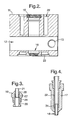
- Gas flow ports 13 and 14 are provided one on each side of the reaction chamber 12 into which supply pipelines for reactant gaseous medium can be coupled. These gas flow ports 13, 14 are shown dotted in Figure 1 . As seen in Figure 2 the gas flow port 13 is close to one end of the slot forming the reaction chamber 12. The gas flow port 14 on the other side is close to the opposite end of the slot forming the reaction chamber 12.
- cylindrical bores 15 and 16 each of which has a portion of increased diameter 15a and 16a respectively.
- the bore 15 receives an electrode holder 17 and electrode 18 shown in Figure 4 .
- the bore 16 receives an electrode holder 19 and electrode 21 shown in Figure 3 .
- annular chamber 22 Surrounding the bore 15 is an annular chamber 22.
- a corresponding annular chamber 23 surrounds the bore 16.
- These annular chambers 22 and 23 are provided to receive a flow of cooling water supplied respectively via cylindrical supply channels 24, 24a, 25. Cooling water flows in through channel 24, out through channel 24a which is connected by an external pipeline to channel 25 leading in to the chamber 23. The cooling water flow exits from chamber 23 via a further channel, not shown as it is behind channel 25 as seen in Figure 1 .
- the outermost portions of the annular chambers 22; 23 are of increased diameter and threaded so that a blank (not shown) can be screwed in to each of them to enclose the water chambers 22, 23.
- a cylindrical electrode holder 19 is shaped to be screw threadedly received in the bore 16 with a head portion of the electrode holder 19 engaging with the increased diameter portion 16a and providing a conical projection into the reaction chamber 12.
- the hollow interior of the electrode holder 19 has a diameter adjacent to the conical portion in which electrode tube 21, made of tungsten or a tungsten alloy, is a sliding fit.
- a short distance inside the holder 19, the diameter of the hollow interior increases gradually to form a tapered shoulder 28.
- a collet 27 encircles the electrode tube 21 and engages against the tapered shoulder 28. The other end of the collet 27 is engaged by the innermost end of inner tube 26 which provides an oppositely directed taper at 29.
- the electrode tube 21 is positioned within the holder 19 so as to provide a desired spacing from electrode tube 18 and then locked in position by tightening the inner tube 26 onto the collet 27.
- the resultant longitudinal compression of the collet 27 provides a radial expansion which clamps the electrode tube 21 in place.
- the electrode holder 17 shown in Figure 4 is longer than electrode holder 19 and adapted to be received in the bore 15 with an increased diameter threaded portion engaging with the threaded portion 15a of the bore 15. Otherwise, the electrode holder 17 is generally similar to the electrode holder 19. Electrode tube 18 and collet 31 are identical with the electrode tube 21 and collet 27 and are clamped in position in the same way by means of inner tube 32.
- the electrode tubes 18, 21 serve to concentrate microwave energy supplied to the reaction chamber 12.
- the electrode tubes have to be of electrically conducting material.
- the electrode holder components are also metallic and therefore electrically conducting, but they could be made from an electrically insulating material if desired.
- a flow of cooling water is supplied to the annular chambers 22 and 23, reactant gaseous medium is supplied to the reaction chamber 12, and microwave energy is fed via a waveguide into the reaction chamber 12.
- An electric potential is established across the electrodes 18 and 21 so as to set up a localised region of plasma between the electrodes in a manner described in detail in patent specification GB 2319941 .
- the apparatus provides for gas flow through the ports 13,'14 and also through the hollow interiors of both electrodes 18 and 21.
- flow of gaseous medium to be excited by the plasma is such as to ensure that gaseous medium passes through the localised plasma.
- this flow arrangement may be reversed, with in-flow through the hollow interiors of the electrode tubes 18,21 and outflow through the ports 13,14.
- Two or even three different gaseous media can be supplied for interaction enhanced by the plasma.
- one gaseous medium can be introduced through gas flow port 13 and another via gas flow port 14, with outflow through one or both of the hollow interiors of the electrodes 18, 21 and their associated holders 17, 19.
- a main gas flow can be arranged to pass in through the hollow interior of one of the electrodes and out through that of the other electrode, whilst a reactant gas is introduced through one or both of the gas flow ports 13,14 and is energized, or converted or part converted into reactant species, by its passage through a curtain of plasma just prior to mixing with the main flow gas in the hollow interior of the electrodes.
- a reactant gas is introduced through one or both of the gas flow ports 13,14 and is energized, or converted or part converted into reactant species, by its passage through a curtain of plasma just prior to mixing with the main flow gas in the hollow interior of the electrodes.
- three different gaseous media may be introduced through respectively gas flow port 13, gas flow port 14 and the hollow interior of one of the electrodes, with outflow of the mixed, reacted gaseous medium through the hollow interior of the other electrode.
- Figures 5 and 6 illustrate a second apparatus which incorporates a number of modifications to facilitate manufacture.
- the main body of this second apparatus is formed from a pair of nearly identical stainless steel components 41, 42 each in the form of a plate with depending side walls so as to have the shape of an elongated "n" in cross section, as may best be seen in Figure 6 .
- the components 41 and 42 are bolted together by bolts, not shown, but the locations of which are schematically illustrated for example at 43 in Figure 5 .
- Assembled in this way, the components 41 and 42 form an interior chamber 44 into which microwave energy may be coupled from a waveguide (not shown) via an adapter plate 45.
- the chamber 44 is closed at the end remote from adapter plate 45 by a cover plate 46.
- a block 48 of PTFE polytetrafluoroethane
- the block 48 exterior is rectangular in shape to fit snugly within the chamber 44.
- the block 48 has a circularly cylindrical aperture in the centre to form a reaction chamber 49.
- one side of the PTFE block 48 has a scalloped recess 51 which communicates with a gas flow pipeline 52 and is arranged to encourage in-flowing gas fed in through pipeline 52 to flow spirally into the reaction chamber 49.
- the objective of imparting spin to the gas flow is to achieve uniform pressure drop in the gas across the electrode tips to optimise the plasma.
- Electrodes 53,54 Aligned with the central axis of the cylindrical reaction chamber 49 are circular apertures in the components 41 and 42. Welded into these apertures is a pair of electrode holders 53,54 of identical construction.
- the electrode holders 53,54 each provide a frusto-conical projection into the reaction chamber 49.
- Each electrode holder is bored to three diameters, with the smallest diameter at 55,56 at the frusto-conical ends.
- the bores 55,56 each open into a wider, threaded, bore 57, 58, each of which in turn opens into a still wider, access, bore 59,61.
- Each electrode 62,63 comprises a hollow tube of tungsten with a short externally threaded end.section of increased diameter.
- the electrodes 62,63 are received respectively in the electrode holders 53, 54, with the threaded portion engaging the co-operating thread provided in the bores 57,58 of the electrode holders.
- the electrodes 62 and 63 can thus be screwed to a desired position setting a required gap between the electrodes within the reaction chamber 49.
- the electrodes 62,63 are then locked in position by respective locknuts 64,65.
- the electrodes 62, 63 and the adapter plate 45 are positioned so as to be separated by 1 ⁇ 4 wavelength of the microwave energy coupled to the reactor in use, so as to concentrate the microwave energy at the'electrodes 62, 63.
- the geometry of the adapter plate is very important for the tuning/optimisation of the microwave coupling to the electrodes 62, 63.
- the geometry of the adapter plate 45 may be fixed as shown, it may be advantageous to provide variable geometry in a similar fashion to an iris aperture to allow manual or automated tuning.
- the ends of the electrode holders 59, 61 remote from the reaction chamber 49 are externally threaded (not shown in Figure 6 ) to facilitate attachment of either a gas supply or a closure nut.
- cooling water jackets 66,67 Surrounding the electrode holders 59 and 61, and sealingly engaged therewith, are cooling water jackets 66,67 which are respectively welded at 68,69 to the components 41, 42. Pipes 71, 72,73,74 provide for flow of water into and out of the water jackets 66,67.
- An electrically insulating lead through 75 with central supply wire 76 enables a high potential trigger pulse to be applied when required to initiate plasma formation.
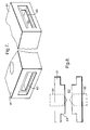
- Figures 7 and 8 illustrate diagrammatically a modified form of block 81 containing a reaction chamber 82.
- the slot forming the reaction chamber 82 is formed with a step 83 so that the reaction chamber 82 is narrower in the region of the electrode tubes, the holders 84,85 for which are indicated only in'dotted outline on Figure 8 .
- This modified configuration can be adopted in either of the examples of Figures 1-4 or Figures 5 , 6 .
- the dimensions of the step 83 are calculated to optimise the coupling efficiency of the microwave energy to the tips of the electrodes.
- Apps for the apparatus of these examples include exciting gases or materials carried in a gas flow for spectroscopic/diagnostic sources and detectors, reformation, catalytic processes such as for NO x reduction or removal of unwanted organic materials, medical sterilisation via excited oxidising species in gas, which can be applied to the sterilisation of artificial joints (eg. hip joints), metal.volatilisation/plasma spraying, surface modification of materials, and vitrification of waste.
- exciting gases or materials carried in a gas flow for spectroscopic/diagnostic sources and detectors, reformation, catalytic processes such as for NO x reduction or removal of unwanted organic materials, medical sterilisation via excited oxidising species in gas, which can be applied to the sterilisation of artificial joints (eg. hip joints), metal.volatilisation/plasma spraying, surface modification of materials, and vitrification of waste.
- the electrodes need not necessarily be made of tungsten, but may, for example, be made from tungsten carbide and/or provided with diamond tips to improve erosion resistance.
- Alternatives to water jacket cooling are possible, such as airflow cooling and/or the use of cooling fins.
- the shaped PTFE block which sealingly separates the reactor chamber 44 from the microwave waveguide, could be replaced with a simple window of PTFE, or other suitable microwave permeable material. In this case, however, the improved control of the gas flow would be forfeited.
- the electrode tubes could be used as "sacrificial electrodes". Rather than replacing short electrode tubes from time to time, a longer electrode tube would be used and fed into the reaction chamber, most conveniently by a motor and feedback sensor mechanism which is adapted to maintain the relative position and separation of the electrode tubes. In this way, feed of electrode tube into the chamber would automatically compensate for erosion at the tube tips.
- a mechanism could provide the additional advantage of achieving auto strike of the plasma by first providing a small electrode separation to initiate the plasma and subsequently increasing the gap to stabilise the discharge intensity and minimise the electrode erosion rate.
Landscapes
- Physics & Mathematics (AREA)
- Engineering & Computer Science (AREA)
- Plasma & Fusion (AREA)
- Chemical & Material Sciences (AREA)
- Analytical Chemistry (AREA)
- Physical Or Chemical Processes And Apparatus (AREA)
Description
- The invention relates to an apparatus in which a plasma is generated in a reaction chamber for enhancing reaction in a gaseous medium supplied to the reaction chamber.
- A number of different forms of apparatus have been devised for making use of plasmas for processing materials or facilitating reactions between gaseous media. The present invention is an improvement upon the form of apparatus described in patent
GB 2273027 GB 2319941 - According to the present invention there is provided a plasma enhanced gas reactor apparatus comprising a reaction chamber, means for coupling microwave radiation into the chamber, a pair of opposed field enhancing electrodes for concentrating microwave energy so as to form plasma in a localised region between the electrodes, gas passages for passing a gaseous medium into and out of the chamber so that the gaseous medium passes through the said localised region of plasma, the electrodes comprising electrically conducting tubes, preferably made of tungsten, held in electrode holders located in the chamber wall, the electrode tubes being removable and replaceable from the electrode holders from the outside of the apparatus.
- In one arrangement according to the invention, at least one of the electrode tubes is clamped in position by means of a collet positioned around the electrode tube and squeezed between a shoulder provided in the electrode holder and a sleeve screwed into the electrode holder to apply longitudinal pressure to the collet, the consequential radial expansion of the collet serving to clamp the electrode in position.
- In an alternative arrangement according to the invention, at least one of the electrode tubes has a threaded portion of larger diameter than the remainder of the tube, the threaded portion on the tube co-operating with a threaded portion of the electrode holder and secured at its chosen location by a locknut.
- Preferably, the reaction chamber is formed by the space between two plate members having side wall portions to form a shape in cross-section in the form of an elongated letter "n", the two plate members being secured together with the side wall portions of one plate member in abutment with the side wall portions of the other plate member.
- The said space between the two plate members is closed at one end by a closure plate and at the other end is adapted for connection to a waveguide for supplying microwave radiation into the reaction chamber.
- Preferably, one or both of the electrode holders has or have a hollow interior which communicates with the hollow interior of the associated electrode tube to provide a passageway for gaseous medium into and/or out of the reaction chamber, and a further passageway for gaseous medium into and/or out of the reaction chamber is provided through a wall of the chamber.
- Specific examples of apparatus embodying the invention will now be described with reference to the drawings filed herewith, in which:
-
Figure 1 is a cross-section of part of a.first apparatus, -
Figure 2 is a cross-section on the line 2-2 inFigure 1 , -
Figure 3 and Figure 4 are cross sections of electrodes and electrode holders forming part of the apparatus ofFigure 1 andFigure 2 , but not shown in those Figures, -
Figure 5 is a perspective view of a second apparatus, -
Figure 6 is a cross-section on the line 6-6 ofFigure 5 , -
Figure 7 is a diagrammatic, split perspective view of part of a modified form of apparatus, and -
Figure 8 is a diagrammatic longitudinal section of the part shown inFigure 7 . - Referring to
Figures 1 and2 , the main body of the apparatus is formed, by casting, fabrication, or machining from solid out of ablock 11 of stainless steel. Thereaction chamber 12 is a slot, which extends through the width of theblock 11. One end of this slot is closed by a cover plate (not shown) and, in use, the other end is attached via an adapter plate (not shown) to a waveguide from a source of microwave energy which is coupled into thereactor chamber 12 via the waveguide. An illustration of a cover plate and adapter plate can be seen inFigure 5 illustrating the second apparatus embodiment. -
Gas flow ports reaction chamber 12 into which supply pipelines for reactant gaseous medium can be coupled. Thesegas flow ports Figure 1 . As seen inFigure 2 thegas flow port 13 is close to one end of the slot forming thereaction chamber 12. Thegas flow port 14 on the other side is close to the opposite end of the slot forming thereaction chamber 12. - In the centre of the
block 11 and extending transversely of the slot forming thereaction chamber 12 arecylindrical bores diameter portion 15a inbore 15 and the portion of smaller diameter in thebore 16. Thebore 15 receives anelectrode holder 17 andelectrode 18 shown inFigure 4 . Thebore 16 receives anelectrode holder 19 andelectrode 21 shown inFigure 3 . Theseelectrode holders electrodes - Surrounding the
bore 15 is anannular chamber 22. A correspondingannular chamber 23 surrounds thebore 16. Theseannular chambers cylindrical supply channels channel 24, out throughchannel 24a which is connected by an external pipeline tochannel 25 leading in to thechamber 23. The cooling water flow exits fromchamber 23 via a further channel, not shown as it is behindchannel 25 as seen inFigure 1 . The outermost portions of theannular chambers 22; 23 are of increased diameter and threaded so that a blank (not shown) can be screwed in to each of them to enclose thewater chambers - Referring to
Figure 3 , acylindrical electrode holder 19 is shaped to be screw threadedly received in thebore 16 with a head portion of theelectrode holder 19 engaging with the increaseddiameter portion 16a and providing a conical projection into thereaction chamber 12. The hollow interior of theelectrode holder 19 has a diameter adjacent to the conical portion in whichelectrode tube 21, made of tungsten or a tungsten alloy, is a sliding fit. A short distance inside theholder 19, the diameter of the hollow interior increases gradually to form atapered shoulder 28. Close to the opposite end of theholder 19, there is a further step increase in diameter and threading provided to receive a screw threaded portion of atube 26. Acollet 27 encircles theelectrode tube 21 and engages against thetapered shoulder 28. The other end of thecollet 27 is engaged by the innermost end ofinner tube 26 which provides an oppositely directed taper at 29. - For assembly, the
electrode tube 21 is positioned within theholder 19 so as to provide a desired spacing fromelectrode tube 18 and then locked in position by tightening theinner tube 26 onto thecollet 27. The resultant longitudinal compression of thecollet 27 provides a radial expansion which clamps theelectrode tube 21 in place. - The
electrode holder 17 shown inFigure 4 is longer thanelectrode holder 19 and adapted to be received in thebore 15 with an increased diameter threaded portion engaging with the threadedportion 15a of thebore 15. Otherwise, theelectrode holder 17 is generally similar to theelectrode holder 19.Electrode tube 18 andcollet 31 are identical with theelectrode tube 21 andcollet 27 and are clamped in position in the same way by means ofinner tube 32. - The
electrode tubes reaction chamber 12. For this purpose the electrode tubes have to be of electrically conducting material. In this example the electrode holder components are also metallic and therefore electrically conducting, but they could be made from an electrically insulating material if desired. - In operation, a flow of cooling water is supplied to the
annular chambers reaction chamber 12, and microwave energy is fed via a waveguide into thereaction chamber 12. An electric potential is established across theelectrodes GB 2319941 - It will be appreciated that the apparatus provides for gas flow through the
ports 13,'14 and also through the hollow interiors of bothelectrodes gas flow ports electrode tubes holders electrode tubes ports gas flow port 13 and another viagas flow port 14, with outflow through one or both of the hollow interiors of theelectrodes holders gas flow ports gas flow port 13,gas flow port 14 and the hollow interior of one of the electrodes, with outflow of the mixed, reacted gaseous medium through the hollow interior of the other electrode. Other flow configurations are possible, but it should be noted that, with the apparatus configuration of this example, an arrangement in which gaseous medium flows in through one of the gas flow ports, say 13, and out through the other gas flow port (14) is unlikely to be satisfactory since it is possible for some of the gas to pass directly from inlet to outlet without interacting with the localised plasma or excited reactant gas emerging therefrom. -
Figures 5 and6 illustrate a second apparatus which incorporates a number of modifications to facilitate manufacture. - The main body of this second apparatus is formed from a pair of nearly identical
stainless steel components Figure 6 . Thecomponents Figure 5 . Assembled in this way, thecomponents interior chamber 44 into which microwave energy may be coupled from a waveguide (not shown) via anadapter plate 45. Thechamber 44 is closed at the end remote fromadapter plate 45 by acover plate 46. Along the abutting surfaces of the depending side walls of thecomponents component 42, an upstanding ridge 47 (seefigure 6 ) and, in theother component 41, a corresponding groove engaged by theridge 47. This ensures there is no leakage path for microwaves out from thechamber 44. - Sandwiched within the
chamber 44 is ablock 48 of PTFE (polytetrafluoroethane). Theblock 48 exterior is rectangular in shape to fit snugly within thechamber 44. Theblock 48 has a circularly cylindrical aperture in the centre to form areaction chamber 49. At one end, one side of thePTFE block 48 has a scallopedrecess 51 which communicates with agas flow pipeline 52 and is arranged to encourage in-flowing gas fed in throughpipeline 52 to flow spirally into thereaction chamber 49. The objective of imparting spin to the gas flow is to achieve uniform pressure drop in the gas across the electrode tips to optimise the plasma. - Encircling the central aperture of the
PTFE block 48 and outside the scallopedrecess 51 is a groove in which is received an "O"ring 60, which, together with matching groove and "0"ring 70 on the other side of thePTFE block 48, serve to seal thereaction chamber 49. - Aligned with the central axis of the
cylindrical reaction chamber 49 are circular apertures in thecomponents electrode holders electrode holders reaction chamber 49. Each electrode holder is bored to three diameters, with the smallest diameter at 55,56 at the frusto-conical ends. Thebores - Each
electrode electrodes electrode holders bores electrodes reaction chamber 49. Theelectrodes respective locknuts - The
electrodes adapter plate 45 are positioned so as to be separated by ¼ wavelength of the microwave energy coupled to the reactor in use, so as to concentrate the microwave energy atthe'electrodes electrodes adapter plate 45 may be fixed as shown, it may be advantageous to provide variable geometry in a similar fashion to an iris aperture to allow manual or automated tuning. - The ends of the
electrode holders reaction chamber 49 are externally threaded (not shown inFigure 6 ) to facilitate attachment of either a gas supply or a closure nut. - Surrounding the
electrode holders water jackets components Pipes water jackets - An electrically insulating lead through 75 with
central supply wire 76 enables a high potential trigger pulse to be applied when required to initiate plasma formation. - In use, the operation of the second apparatus as shown in
Figures 5 and6 is parallel with that described for the apparatus ofFigures 1 to 4 . Only three gas flow ports are shown in the apparatus ofFigures 5 and6 , but it will be appreciated that a further gas flow port into thereaction chamber 49 may readily be provided diametrically opposite the one shown at 52, 51. -
Figures 7 and 8 illustrate diagrammatically a modified form ofblock 81 containing areaction chamber 82. The slot forming thereaction chamber 82 is formed with astep 83 so that thereaction chamber 82 is narrower in the region of the electrode tubes, theholders Figure 8 . This modified configuration can be adopted in either of the examples ofFigures 1-4 orFigures 5 ,6 . The dimensions of thestep 83 are calculated to optimise the coupling efficiency of the microwave energy to the tips of the electrodes. - Applications for the apparatus of these examples include exciting gases or materials carried in a gas flow for spectroscopic/diagnostic sources and detectors, reformation, catalytic processes such as for NOx reduction or removal of unwanted organic materials, medical sterilisation via excited oxidising species in gas, which can be applied to the sterilisation of artificial joints (eg. hip joints), metal.volatilisation/plasma spraying, surface modification of materials, and vitrification of waste.
- The invention is not restricted to the details of the foregoing examples. For instance, the electrodes need not necessarily be made of tungsten, but may, for example, be made from tungsten carbide and/or provided with diamond tips to improve erosion resistance. Alternatives to water jacket cooling are possible, such as airflow cooling and/or the use of cooling fins. The shaped PTFE block, which sealingly separates the
reactor chamber 44 from the microwave waveguide, could be replaced with a simple window of PTFE, or other suitable microwave permeable material. In this case, however, the improved control of the gas flow would be forfeited. - The electrode tubes could be used as "sacrificial electrodes". Rather than replacing short electrode tubes from time to time, a longer electrode tube would be used and fed into the reaction chamber, most conveniently by a motor and feedback sensor mechanism which is adapted to maintain the relative position and separation of the electrode tubes. In this way, feed of electrode tube into the chamber would automatically compensate for erosion at the tube tips. Such a mechanism could provide the additional advantage of achieving auto strike of the plasma by first providing a small electrode separation to initiate the plasma and subsequently increasing the gap to stabilise the discharge intensity and minimise the electrode erosion rate.
Claims (7)
- A plasma enhanced gas reactor apparatus comprising a reaction chamber (12;44;82), means for coupling microwave radiation into the chamber, a pair of opposed field enhancing electrodes (18,21;62,63) for concentrating microwave energy so as to form plasma in a localised region between the electrodes (18,21:62,63), gas passages (13,14,18,21;51,51,62,63) for passing a gaseous medium into and out of the chamber (12;44;82) so that the gaseous medium passes through the said localised region of plasma, characterised in that the electrodes (18,21;62,63) comprise electrically conducting tubes (18,21;62,63) held in electrode holders (17,19;53,54) located in the chamber wall, the electrode tubes being removable and replaceable from the electrode holders (17,19;53,54) from the outside of the apparatus.
- Apparatus as claimed in claim 1, wherein the electrodes (18,21;62,63) comprise tungsten tubes.
- Apparatus as claimed in claim 1 or 2, wherein at least one of the electrode tubes (18,21) is clamped in position by means of a collet (27,31) positioned around the electrode tube (21,18) and squeezed between a shoulder (28) provided in the electrode holder (19,17) and a sleeve(26,32) screwed into the electrode holder (19,17) to apply longitudinal pressure to the collet (27,31), the consequential radial expansion of the collet (27,31) serving to clamp the electrode tube (18,21) in position.
- Apparatus as claimed in claim 1 or 2, wherein at least one of the electrode tubes (62,63) has a threaded portion of larger diameter than the remainder of the tube, the threaded portion on the tube (62,63) cooperating with a threaded portion of the electrode holder (53,54)and secured at its chosen location by a locknut (64,65).
- Apparatus as claimed in any of the preceding claims, wherein the reaction chamber (44) is formed by the space between two plate members (41,42) having side wall portions to form a shape in cross-section in the form of an elongated letter "n" and secured together with the side wall portions of one plate member (41) in abutment with the side wall portions of the other plate member (42).
- Apparatus as claimed in claim 5, wherein the said space between the two plate members (41,42) is closed at one end by a closure plate (46) and at the other end is adapted (45) for connection to a waveguide for supplying microwave radiation into the reaction chamber (44).
- Apparatus as claimed in any of the preceding claims, wherein one or both of the electrode holders (17,19;53,54) has or have a hollow interior which communicates with the hollow interior of the associated electrode tube (18,21;62,63), to provide a passageway for gaseous medium into and/or out of the reaction chamber (12;44;82), and a further passageway (13,14,52,51) for gaseous medium into and/or out of the reaction chamber (12;44;82) is provided through a wall of the chamber (12;44;82).
Applications Claiming Priority (3)
| Application Number | Priority Date | Filing Date | Title |
|---|---|---|---|
| GB0021815 | 2000-09-06 | ||
| GBGB0021815.6A GB0021815D0 (en) | 2000-09-06 | 2000-09-06 | Plasma enhanced gas reactor |
| PCT/GB2001/003767 WO2002021567A1 (en) | 2000-09-06 | 2001-08-22 | Plasma enhanced gas reactor |
Publications (2)
| Publication Number | Publication Date |
|---|---|
| EP1316105A1 EP1316105A1 (en) | 2003-06-04 |
| EP1316105B1 true EP1316105B1 (en) | 2016-10-05 |
Family
ID=9898912
Family Applications (1)
| Application Number | Title | Priority Date | Filing Date |
|---|---|---|---|
| EP01960916.3A Expired - Lifetime EP1316105B1 (en) | 2000-09-06 | 2001-08-22 | Plasma enhanced gas reactor |
Country Status (6)
| Country | Link |
|---|---|
| US (1) | US6863870B2 (en) |
| EP (1) | EP1316105B1 (en) |
| JP (1) | JP5462992B2 (en) |
| AU (1) | AU2001282306A1 (en) |
| GB (1) | GB0021815D0 (en) |
| WO (1) | WO2002021567A1 (en) |
Families Citing this family (10)
| Publication number | Priority date | Publication date | Assignee | Title |
|---|---|---|---|---|
| GB0126419D0 (en) * | 2001-11-03 | 2002-01-02 | Accentus Plc | Microwave plasma generator |
| DE10310623B8 (en) * | 2003-03-10 | 2005-12-01 | Fraunhofer-Gesellschaft zur Förderung der angewandten Forschung e.V. | Method and apparatus for generating a plasma by electrical discharge in a discharge space |
| FR2880236B1 (en) * | 2004-12-23 | 2007-03-30 | Air Liquide | MICROWAVE PLASMA EXCITATORS |
| JP4761442B2 (en) * | 2005-08-08 | 2011-08-31 | 芝浦メカトロニクス株式会社 | Plasma generator and plasma processing apparatus |
| US20090188894A1 (en) * | 2008-01-28 | 2009-07-30 | Honeywell International Inc. | Welding guide nozzle including nozzle tip for precision weld wire positioning |
| US9144858B2 (en) * | 2011-11-18 | 2015-09-29 | Recarbon Inc. | Plasma generating system having movable electrodes |
| GB2553752A (en) * | 2016-07-01 | 2018-03-21 | Arcs Energy Ltd | Fluid treatment apparatus and method |
| WO2018226917A2 (en) * | 2017-06-08 | 2018-12-13 | Industrial Heat, Llc | Low cost plate reactor for exothermic reactions |
| WO2019083645A2 (en) * | 2017-09-20 | 2019-05-02 | Ih Ip Holdings Limited | Modular reactor system for exothermic reactions |
| BE1030331B1 (en) * | 2022-03-11 | 2023-10-09 | D Crbn Bv | A SOLID PARALLEL PLASMA REACTOR FOR GAS CONVERSION APPLICATIONS |
Family Cites Families (11)
| Publication number | Priority date | Publication date | Assignee | Title |
|---|---|---|---|---|
| US3132996A (en) | 1962-12-10 | 1964-05-12 | William R Baker | Contra-rotating plasma system |
| JPS5256078A (en) * | 1975-11-04 | 1977-05-09 | Iwatani & Co | Aerial discharge reaction |
| JPS54107893A (en) * | 1978-02-13 | 1979-08-24 | Mitsubishi Electric Corp | Ozonizer |
| US4801435A (en) | 1986-09-08 | 1989-01-31 | Plasma Holdings N.V. | Hybrid plasma reactor |
| JPH075628Y2 (en) * | 1990-05-30 | 1995-02-08 | 株式会社島津製作所 | Vacuum film forming equipment |
| JPH05290751A (en) * | 1992-04-14 | 1993-11-05 | Mitsubishi Heavy Ind Ltd | High frequency type ion source |
| EP0577344A1 (en) | 1992-06-25 | 1994-01-05 | CARTER & OGILVIE RESEARCH PTY LIMITED | Material treatment method and apparatus |
| GB9224745D0 (en) | 1992-11-26 | 1993-01-13 | Atomic Energy Authority Uk | Microwave plasma generator |
| DE69726830T2 (en) * | 1996-11-28 | 2004-10-07 | Accentus Plc Didcot | Method and device for the plasma-chemical treatment of gases |
| JPH1154297A (en) * | 1997-08-07 | 1999-02-26 | Nippon Paint Co Ltd | Portable small surface treatment device and discharge treatment member of portable small surface treatment device |
| JP3099065B2 (en) * | 1999-01-29 | 2000-10-16 | 工業技術院長 | Vacuum deposition equipment |
-
2000
- 2000-09-06 GB GBGB0021815.6A patent/GB0021815D0/en not_active Ceased
-
2001
- 2001-08-22 US US10/363,414 patent/US6863870B2/en not_active Expired - Lifetime
- 2001-08-22 AU AU2001282306A patent/AU2001282306A1/en not_active Abandoned
- 2001-08-22 JP JP2002525892A patent/JP5462992B2/en not_active Expired - Lifetime
- 2001-08-22 WO PCT/GB2001/003767 patent/WO2002021567A1/en not_active Ceased
- 2001-08-22 EP EP01960916.3A patent/EP1316105B1/en not_active Expired - Lifetime
Also Published As
| Publication number | Publication date |
|---|---|
| JP5462992B2 (en) | 2014-04-02 |
| US6863870B2 (en) | 2005-03-08 |
| US20030175181A1 (en) | 2003-09-18 |
| GB0021815D0 (en) | 2000-10-18 |
| AU2001282306A1 (en) | 2002-03-22 |
| JP2004508682A (en) | 2004-03-18 |
| EP1316105A1 (en) | 2003-06-04 |
| WO2002021567A1 (en) | 2002-03-14 |
Similar Documents
| Publication | Publication Date | Title |
|---|---|---|
| US6863870B2 (en) | Plasma enhanced gas reactor | |
| US5418430A (en) | Plasma generator with field-enhancing electrodes | |
| JP4339588B2 (en) | Apparatus for processing gases using plasma | |
| US7442271B2 (en) | Miniature microwave plasma torch application and method of use thereof | |
| US4924061A (en) | Microwave plasma torch, device comprising such a torch and process for manufacturing powder by the use thereof | |
| DE19814812C2 (en) | Plasma torch with a microwave transmitter | |
| EP2082622B1 (en) | Method and apparatus for alignment of components of a plasma arc torch | |
| RU2071644C1 (en) | Plasma torch | |
| EP0845287B1 (en) | Process and device for plasma gas treatment | |
| US6852943B2 (en) | Strain relief mechanism for a plasma arc torch | |
| EP1305604B1 (en) | Plasma source for spectrometry | |
| US20060151447A1 (en) | Method and apparatus for alignment of components of a plasma arc torch | |
| EP0748149A1 (en) | Plasma arc torch having water injection nozzle assembly | |
| US5688417A (en) | DC arc plasma torch, for obtaining a chemical substance by decomposition of a plasma-generating gas | |
| KR200493866Y1 (en) | thermal plasma torch | |
| EP1632114B1 (en) | Cascade source and a method for controlling the cascade source | |
| US4628177A (en) | Arc welding torch | |
| EP1412126B1 (en) | Laser-plasma hybrid welding method | |
| US20230276562A1 (en) | High-Power Plasma Torch with Dielectric Resonator | |
| DE69214878T2 (en) | High enthalpy plasma torch | |
| NO163409B (en) | ANALOGY PROCEDURE FOR THE PREPARATION OF NEW THERAPEUTIC ACTIVE NITROSOURE ADDES. | |
| US4645973A (en) | Hyperfrequency energy plasma torch | |
| CA2260505C (en) | Plasma producer with a holder | |
| US8581496B2 (en) | Self-igniting long arc plasma torch | |
| RU194071U1 (en) | Plasma torch |
Legal Events
| Date | Code | Title | Description |
|---|---|---|---|
| PUAI | Public reference made under article 153(3) epc to a published international application that has entered the european phase |
Free format text: ORIGINAL CODE: 0009012 |
|
| 17P | Request for examination filed |
Effective date: 20030206 |
|
| AK | Designated contracting states |
Designated state(s): AT BE CH CY DE DK ES FI FR GB GR IE IT LI LU MC NL PT SE TR |
|
| AX | Request for extension of the european patent |
Extension state: AL LT LV MK RO SI |
|
| RAP1 | Party data changed (applicant data changed or rights of an application transferred) |
Owner name: ACCENTUS PLC |
|
| RAP1 | Party data changed (applicant data changed or rights of an application transferred) |
Owner name: ACCENTUS PLC |
|
| RAP1 | Party data changed (applicant data changed or rights of an application transferred) |
Owner name: QINETIQ LIMITED |
|
| 17Q | First examination report despatched |
Effective date: 20090416 |
|
| RAP1 | Party data changed (applicant data changed or rights of an application transferred) |
Owner name: QINETIQ LIMITED |
|
| GRAP | Despatch of communication of intention to grant a patent |
Free format text: ORIGINAL CODE: EPIDOSNIGR1 |
|
| INTG | Intention to grant announced |
Effective date: 20160609 |
|
| GRAS | Grant fee paid |
Free format text: ORIGINAL CODE: EPIDOSNIGR3 |
|
| GRAA | (expected) grant |
Free format text: ORIGINAL CODE: 0009210 |
|
| AK | Designated contracting states |
Kind code of ref document: B1 Designated state(s): AT BE CH CY DE DK ES FI FR GB GR IE IT LI LU MC NL PT SE TR |
|
| REG | Reference to a national code |
Ref country code: GB Ref legal event code: FG4D |
|
| REG | Reference to a national code |
Ref country code: CH Ref legal event code: EP |
|
| REG | Reference to a national code |
Ref country code: AT Ref legal event code: REF Ref document number: 835269 Country of ref document: AT Kind code of ref document: T Effective date: 20161015 |
|
| REG | Reference to a national code |
Ref country code: IE Ref legal event code: FG4D |
|
| REG | Reference to a national code |
Ref country code: DE Ref legal event code: R096 Ref document number: 60150150 Country of ref document: DE |
|
| REG | Reference to a national code |
Ref country code: NL Ref legal event code: MP Effective date: 20161005 |
|
| REG | Reference to a national code |
Ref country code: AT Ref legal event code: MK05 Ref document number: 835269 Country of ref document: AT Kind code of ref document: T Effective date: 20161005 |
|
| PG25 | Lapsed in a contracting state [announced via postgrant information from national office to epo] |
Ref country code: SE Free format text: LAPSE BECAUSE OF FAILURE TO SUBMIT A TRANSLATION OF THE DESCRIPTION OR TO PAY THE FEE WITHIN THE PRESCRIBED TIME-LIMIT Effective date: 20161005 Ref country code: GR Free format text: LAPSE BECAUSE OF FAILURE TO SUBMIT A TRANSLATION OF THE DESCRIPTION OR TO PAY THE FEE WITHIN THE PRESCRIBED TIME-LIMIT Effective date: 20170106 |
|
| PG25 | Lapsed in a contracting state [announced via postgrant information from national office to epo] |
Ref country code: BE Free format text: LAPSE BECAUSE OF FAILURE TO SUBMIT A TRANSLATION OF THE DESCRIPTION OR TO PAY THE FEE WITHIN THE PRESCRIBED TIME-LIMIT Effective date: 20161005 Ref country code: PT Free format text: LAPSE BECAUSE OF FAILURE TO SUBMIT A TRANSLATION OF THE DESCRIPTION OR TO PAY THE FEE WITHIN THE PRESCRIBED TIME-LIMIT Effective date: 20170206 Ref country code: FI Free format text: LAPSE BECAUSE OF FAILURE TO SUBMIT A TRANSLATION OF THE DESCRIPTION OR TO PAY THE FEE WITHIN THE PRESCRIBED TIME-LIMIT Effective date: 20161005 Ref country code: AT Free format text: LAPSE BECAUSE OF FAILURE TO SUBMIT A TRANSLATION OF THE DESCRIPTION OR TO PAY THE FEE WITHIN THE PRESCRIBED TIME-LIMIT Effective date: 20161005 Ref country code: NL Free format text: LAPSE BECAUSE OF FAILURE TO SUBMIT A TRANSLATION OF THE DESCRIPTION OR TO PAY THE FEE WITHIN THE PRESCRIBED TIME-LIMIT Effective date: 20161005 Ref country code: ES Free format text: LAPSE BECAUSE OF FAILURE TO SUBMIT A TRANSLATION OF THE DESCRIPTION OR TO PAY THE FEE WITHIN THE PRESCRIBED TIME-LIMIT Effective date: 20161005 |
|
| REG | Reference to a national code |
Ref country code: DE Ref legal event code: R097 Ref document number: 60150150 Country of ref document: DE |
|
| PG25 | Lapsed in a contracting state [announced via postgrant information from national office to epo] |
Ref country code: DK Free format text: LAPSE BECAUSE OF FAILURE TO SUBMIT A TRANSLATION OF THE DESCRIPTION OR TO PAY THE FEE WITHIN THE PRESCRIBED TIME-LIMIT Effective date: 20161005 |
|
| PLBE | No opposition filed within time limit |
Free format text: ORIGINAL CODE: 0009261 |
|
| STAA | Information on the status of an ep patent application or granted ep patent |
Free format text: STATUS: NO OPPOSITION FILED WITHIN TIME LIMIT |
|
| REG | Reference to a national code |
Ref country code: FR Ref legal event code: PLFP Year of fee payment: 17 |
|
| PG25 | Lapsed in a contracting state [announced via postgrant information from national office to epo] |
Ref country code: IT Free format text: LAPSE BECAUSE OF FAILURE TO SUBMIT A TRANSLATION OF THE DESCRIPTION OR TO PAY THE FEE WITHIN THE PRESCRIBED TIME-LIMIT Effective date: 20161005 |
|
| 26N | No opposition filed |
Effective date: 20170706 |
|
| REG | Reference to a national code |
Ref country code: CH Ref legal event code: PL |
|
| PG25 | Lapsed in a contracting state [announced via postgrant information from national office to epo] |
Ref country code: MC Free format text: LAPSE BECAUSE OF FAILURE TO SUBMIT A TRANSLATION OF THE DESCRIPTION OR TO PAY THE FEE WITHIN THE PRESCRIBED TIME-LIMIT Effective date: 20161005 |
|
| PG25 | Lapsed in a contracting state [announced via postgrant information from national office to epo] |
Ref country code: LI Free format text: LAPSE BECAUSE OF NON-PAYMENT OF DUE FEES Effective date: 20170831 Ref country code: CH Free format text: LAPSE BECAUSE OF NON-PAYMENT OF DUE FEES Effective date: 20170831 |
|
| REG | Reference to a national code |
Ref country code: IE Ref legal event code: MM4A |
|
| PG25 | Lapsed in a contracting state [announced via postgrant information from national office to epo] |
Ref country code: LU Free format text: LAPSE BECAUSE OF NON-PAYMENT OF DUE FEES Effective date: 20170822 |
|
| PG25 | Lapsed in a contracting state [announced via postgrant information from national office to epo] |
Ref country code: IE Free format text: LAPSE BECAUSE OF NON-PAYMENT OF DUE FEES Effective date: 20170822 |
|
| REG | Reference to a national code |
Ref country code: FR Ref legal event code: PLFP Year of fee payment: 18 |
|
| PG25 | Lapsed in a contracting state [announced via postgrant information from national office to epo] |
Ref country code: CY Free format text: LAPSE BECAUSE OF NON-PAYMENT OF DUE FEES Effective date: 20161005 |
|
| PG25 | Lapsed in a contracting state [announced via postgrant information from national office to epo] |
Ref country code: TR Free format text: LAPSE BECAUSE OF FAILURE TO SUBMIT A TRANSLATION OF THE DESCRIPTION OR TO PAY THE FEE WITHIN THE PRESCRIBED TIME-LIMIT Effective date: 20161005 |
|
| PGFP | Annual fee paid to national office [announced via postgrant information from national office to epo] |
Ref country code: GB Payment date: 20200827 Year of fee payment: 20 Ref country code: FR Payment date: 20200825 Year of fee payment: 20 Ref country code: DE Payment date: 20200827 Year of fee payment: 20 |
|
| REG | Reference to a national code |
Ref country code: DE Ref legal event code: R071 Ref document number: 60150150 Country of ref document: DE |
|
| REG | Reference to a national code |
Ref country code: GB Ref legal event code: PE20 Expiry date: 20210821 |
|
| PG25 | Lapsed in a contracting state [announced via postgrant information from national office to epo] |
Ref country code: GB Free format text: LAPSE BECAUSE OF EXPIRATION OF PROTECTION Effective date: 20210821 |