EP1315647B1 - Device for mechanically coupling a rail brake on a steering bogie of a rail vehicle (brake power driver) - Google Patents
Device for mechanically coupling a rail brake on a steering bogie of a rail vehicle (brake power driver) Download PDFInfo
- Publication number
- EP1315647B1 EP1315647B1 EP01969656A EP01969656A EP1315647B1 EP 1315647 B1 EP1315647 B1 EP 1315647B1 EP 01969656 A EP01969656 A EP 01969656A EP 01969656 A EP01969656 A EP 01969656A EP 1315647 B1 EP1315647 B1 EP 1315647B1
- Authority
- EP
- European Patent Office
- Prior art keywords
- brake
- rail
- brake frame
- spring
- bogie
- Prior art date
- Legal status (The legal status is an assumption and is not a legal conclusion. Google has not performed a legal analysis and makes no representation as to the accuracy of the status listed.)
- Expired - Lifetime
Links
- 230000008878 coupling Effects 0.000 title claims abstract description 11
- 238000010168 coupling process Methods 0.000 title claims abstract description 11
- 238000005859 coupling reaction Methods 0.000 title claims abstract description 11
- 239000000463 material Substances 0.000 claims abstract description 6
- 230000006835 compression Effects 0.000 claims description 5
- 238000007906 compression Methods 0.000 claims description 5
- 229920001971 elastomer Polymers 0.000 claims description 5
- 229910000639 Spring steel Inorganic materials 0.000 claims description 4
- 229910000851 Alloy steel Inorganic materials 0.000 claims description 3
- 229910052751 metal Inorganic materials 0.000 claims description 3
- 239000002184 metal Substances 0.000 claims description 3
- 229910001369 Brass Inorganic materials 0.000 claims description 2
- PWHULOQIROXLJO-UHFFFAOYSA-N Manganese Chemical compound [Mn] PWHULOQIROXLJO-UHFFFAOYSA-N 0.000 claims description 2
- 229910045601 alloy Inorganic materials 0.000 claims description 2
- 239000000956 alloy Substances 0.000 claims description 2
- 239000010951 brass Substances 0.000 claims description 2
- 229910052748 manganese Inorganic materials 0.000 claims description 2
- 239000011572 manganese Substances 0.000 claims description 2
- 241000282472 Canis lupus familiaris Species 0.000 claims 5
- 239000000806 elastomer Substances 0.000 claims 1
- 230000000694 effects Effects 0.000 abstract description 2
- 230000005540 biological transmission Effects 0.000 description 4
- 238000006073 displacement reaction Methods 0.000 description 3
- 229910000831 Steel Inorganic materials 0.000 description 2
- 239000000969 carrier Substances 0.000 description 2
- 230000003993 interaction Effects 0.000 description 2
- 239000010959 steel Substances 0.000 description 2
- BGPVFRJUHWVFKM-UHFFFAOYSA-N N1=C2C=CC=CC2=[N+]([O-])C1(CC1)CCC21N=C1C=CC=CC1=[N+]2[O-] Chemical compound N1=C2C=CC=CC2=[N+]([O-])C1(CC1)CCC21N=C1C=CC=CC1=[N+]2[O-] BGPVFRJUHWVFKM-UHFFFAOYSA-N 0.000 description 1
- 230000009471 action Effects 0.000 description 1
- 230000008901 benefit Effects 0.000 description 1
- 230000001419 dependent effect Effects 0.000 description 1
- 238000011161 development Methods 0.000 description 1
- 230000018109 developmental process Effects 0.000 description 1
- 230000005489 elastic deformation Effects 0.000 description 1
- 239000013536 elastomeric material Substances 0.000 description 1
- 238000012423 maintenance Methods 0.000 description 1
- 238000004519 manufacturing process Methods 0.000 description 1
- 238000012986 modification Methods 0.000 description 1
- 230000004048 modification Effects 0.000 description 1
- 230000009467 reduction Effects 0.000 description 1
- 230000035939 shock Effects 0.000 description 1
- 230000001360 synchronised effect Effects 0.000 description 1
- 238000003466 welding Methods 0.000 description 1
Images


Classifications
-
- B—PERFORMING OPERATIONS; TRANSPORTING
- B61—RAILWAYS
- B61H—BRAKES OR OTHER RETARDING DEVICES SPECIALLY ADAPTED FOR RAIL VEHICLES; ARRANGEMENT OR DISPOSITION THEREOF IN RAIL VEHICLES
- B61H7/00—Brakes with braking members co-operating with the track
- B61H7/02—Scotch blocks, skids, or like track-engaging shoes
- B61H7/04—Scotch blocks, skids, or like track-engaging shoes attached to railway vehicles
- B61H7/06—Skids
- B61H7/08—Skids electromagnetically operated
-
- B—PERFORMING OPERATIONS; TRANSPORTING
- B60—VEHICLES IN GENERAL
- B60L—PROPULSION OF ELECTRICALLY-PROPELLED VEHICLES; SUPPLYING ELECTRIC POWER FOR AUXILIARY EQUIPMENT OF ELECTRICALLY-PROPELLED VEHICLES; ELECTRODYNAMIC BRAKE SYSTEMS FOR VEHICLES IN GENERAL; MAGNETIC SUSPENSION OR LEVITATION FOR VEHICLES; MONITORING OPERATING VARIABLES OF ELECTRICALLY-PROPELLED VEHICLES; ELECTRIC SAFETY DEVICES FOR ELECTRICALLY-PROPELLED VEHICLES
- B60L2200/00—Type of vehicles
- B60L2200/26—Rail vehicles
Definitions
- the invention relates to a device for the mechanical coupling of a rail brake on a bogie of a rail vehicle, as indicated in the preamble of claim 1.
- the bogie of a rail vehicle usually carries as a two- or multi-axis Chassis the vehicle body and is about a vertical axis with respect to the vehicle body rotatable, so that the rail vehicle thereby a high running quality, especially in Track curvatures achieved.
- a service brake of a rail vehicle of interest here Art is provided on the bogie rail brake, the is preferably designed as a magnetic rail brake or as an eddy current brake.
- a Rail brake usually consists of an elongated arrangement of electrical Brake magnet, the current when energized and lowered in the direction of the rail magnetic attractions initiate a stunt of the rail vehicle.
- a generic device is known from DE 26 14 298 A1.
- the frontal Ends of the magnet carrier are supported in guides which extend from the journal bearings of the Wheelsets extend vertically downwards. In this way is the magnetic carrier between the braking position and the release position lowered or raised.
- the object of the present invention is a generic Device for mechanically coupling a rail brake to a bogie a rail vehicle to further improve that the burden of Brake frame is minimized in the transmission of braking forces on the bogie.
- the object is based on a device according to the preamble of claim 1 solved in conjunction with its characterizing features.
- the subsequent dependent ones Claims give advantageous developments of the invention again.
- the invention includes the technical teaching that one made of a hard material Wear plate via a spring arrangement with the stop surface of the Mit Sprintanschlags is connected to result in an acting in the longitudinal and transverse elastic To form coupling point.
- the wear plate with the spring arrangement may alternatively also opposite, i. e. on the side of the stop area of the track holder arrangement, to be appropriate.
- the advantage of the solution according to the invention lies in particular in a load reduction the brake frame during braking operation, in which now an elastic displacement the existing between the brake frame and the bogie investment points in the longitudinal and transverse direction is made possible.
- the elastic displacement can are derived from the stiffness of the spring assembly.
- the invention is characterized by the stress-optimizing measures comparatively easier to execute and owns the elasticity of the coupling point a higher security against mechanical overload, so that in extreme cases to be feared delay of the brake frame prevented can be. Furthermore, at the beginning of each braking the shock between the Rail brake carrying brake frame and the bogie reduced.
- the spring assembly consists of a plate-like elastomeric Material, such as a conventional rubber element.
- a plate-like elastomeric Material such as a conventional rubber element.
- the spring assembly with the wear plate as a prefabricated rubber-metal part be executed.
- This design allows not only an effective production but also a easy mounting on the bogie or brake frame.
- the assembly can, for example done by screws, so that a worn plate wear even in case of maintenance together with the elastomeric spring arrangement is easily replaceable.
- the spring arrangement as a plate-like rubber element
- these compression springs can, for example, next to each other and in parallel connected between the wear plate and the bogie or the brake frame be provided to during the braking operation, in particular in the longitudinal direction apply required high spring force.
- the metallic compression spring can vary depending on Loading preferably in the manner of a coil spring, a leaf spring, a plate spring or be formed.
- the wear plate used in the inventive solution made of a hard steel alloy with a manganese content, for a particularly high wear resistance to achieve.
- the wear plate can also from another suitable Hard material - for example, from a brass alloy - exist. The choice of material is here too depends on the mechanical load of the component.
- a brake frame consists of Figure 1 essentially of two parallel track width spaced apart Magnetträgems 1a and 1b, which together with one of two track holders 2a and 2b existing track holder assembly in the form of a rectangle are.
- the track holder 2a and 2b and the magnetic carriers 1a and 1b are made of steel profiles are bolted together to form the brake frame.
- At the two magnet carriers 1a and 1b are each an electric brake magnet 3a and 3b attached.
- To brake act the brake magnets 3a and 3b, each with an associated rail 4 of the track (here symbolically indicated) together.
- driver stops 8a, 8b, 8c, 8d are opposite the brake frame while maintaining a longitudinal section which will be explained in more detail later. and transverse play arranged to the vertical mobility of the brake frame and its To enable leadership.
- the driver stops 8a, 8b, 8c, 8d are frame inside placed so that they can act in both directions. In the one direction while the driver stops 8a and 8b come to rest on the brake frame; in the other direction of travel, however, the driver stops 8c and 8d.
- the driver stop attached to the bogie 6 (dot-dash line) 8 a statically stable box-shaped cross section.
- An abutment surface 9 of Mitaueranschlags 8 is opposite a corresponding stop portion 10th arranged at the end of the track holder 2. This is where the brake force transmission from Brake frame on the bogie 6.
- the unloaded condition there is a cross between the Mitaueranschlag 8 and that vertically angled surface of the stop area 10, which is parallel to the plane of movement of the magnetic carrier 1.
- a longitudinal game exists in the unloaded state between the arranged in the plane of movement of the track holder 2 Partial surface of the stop portion 10 and the stop surface 9 of the Mitaueranschlags 8.
- the longitudinal and transverse play compensates for small relative displacements between the brake frame and the bogie 6, due to the interaction the brake magnets 3 with the track during braking operation occur and ensure a guided vertical mobility of the brake frame.
- Mitaueran Farb 8 is shown individually.
- the driver bogie extending downwardly from the bogie 6 in the vertical direction 8 consists, as the section A - A shows, from four flat steel profile parts through Welding are connected to the box-shaped arrangement.
- the spring assembly 11 is here in the form of a plate-like trained rubber elements running. This in turn is a wear plate 12 attached from a wear-resistant Mn-steel alloy. While in braking mode fixed contact the wear plate 12 on the not shown here corresponding stop area
- the brake frame is formed by the spring action of the spring assembly 11 a longitudinal and transverse elastic coupling point, so that the brake frame during braking operation can always take a position optimal load.
- the invention is not limited to the preferred embodiment described above. Rather, constructive modifications thereof are conceivable, even at engage differently embodiment in the claimed by the invention scope.
- the invention is not particularly concerned with the use of an elastomeric body limited as a spring arrangement. This can also, for example, from a spring steel made spring assembly, wherein on the shape of the spring steel, the required Feaersteiftechnik is adaptable depending on the application.
- the shape of the Brake frame is not limited to a rectangular arrangement. Another arrangement is also conceivable, while maintaining the track pitch a synchronous vertical Mobility of the brake magnets ensures.
Landscapes
- Physics & Mathematics (AREA)
- Electromagnetism (AREA)
- Engineering & Computer Science (AREA)
- Mechanical Engineering (AREA)
- Braking Arrangements (AREA)
- Braking Systems And Boosters (AREA)
Abstract
Description
Die Erfindung betrifft eine Vorrichtung zur mechanischen Kopplung einer Schienenbremse an einem Drehgestell eines Schienenfahrzeuges, wie im Oberbegriff des Anspruchs 1 angegeben.The invention relates to a device for the mechanical coupling of a rail brake on a bogie of a rail vehicle, as indicated in the preamble of claim 1.
Das Drehgestell eines Schienenfahrzeuges trägt gewöhnlich als zwei- oder mehrachsiges Fahrgestell den Fahrzeugaufbau und ist um eine senkrechte Achse bezüglich des Fahrzeugaufbaus drehbar, so daß das Schienenfahrzeug hierdurch eine hohe Laufgüte insbesondere in Gleiskrümmungen erzielt. Als Betriebsbremse eines Schienenfahrzeuges der hier interessierenden Art ist eine am Drehgestell angeordnete Schienenbremse vorgesehen, die vorzugsweise als Magnetschienenbremse oder als Wirbelstrombremse ausgebildet ist. Eine Schienenbremse besteht gewöhnlich aus einer langgestreckten Anordnung von elektrischen Bremsmagneten, die bei Bestromung und Absenkung in Richtung der Schiene aufgrund der magnetischen Anziehungskräfte eine Bremsung des Schienenfahrzeuges einleiten.The bogie of a rail vehicle usually carries as a two- or multi-axis Chassis the vehicle body and is about a vertical axis with respect to the vehicle body rotatable, so that the rail vehicle thereby a high running quality, especially in Track curvatures achieved. As a service brake of a rail vehicle of interest here Art is provided on the bogie rail brake, the is preferably designed as a magnetic rail brake or as an eddy current brake. A Rail brake usually consists of an elongated arrangement of electrical Brake magnet, the current when energized and lowered in the direction of the rail magnetic attractions initiate a stunt of the rail vehicle.
Eine gattungsgemäße Vorrichtung ist aus der DE 26 14 298 A1 bekannt. Zur mechanischen Kopplung einer Schienenbremse am Drehgestell, d.h. zur Übertragung der Bremskraft zwischen den beiden Baueinheiten, ist an den zu beiden Seiten der Radsätze sich erstreckenden Drehgestellrahmen ein Magnetträger einer Wirbelstrombremse mit Hilfe von druckmittelbeaufschlagbaren Betätigungszylindern höhenverstellbar angeordnet. Die stirnseitigen Enden des Magnetträgers sind in Führungen gehaltert, welche sich von den Achslagern der Radsätze aus senkrecht nach unten gerichtet erstrecken. Auf diese Weise ist der Magnetträger zwischen der Bremsstellung und der Lösestellung absenkbar bzw. anhebbar geführt.A generic device is known from DE 26 14 298 A1. To the mechanical Coupling of a rail brake on the bogie, i. for transmitting the braking force between the two units, is at the on both sides of the wheelsets extending Bogie frame a magnetic carrier of an eddy current brake with the help of druckmittelbeaufschlagbaren Actuating cylinders arranged height adjustable. The frontal Ends of the magnet carrier are supported in guides which extend from the journal bearings of the Wheelsets extend vertically downwards. In this way is the magnetic carrier between the braking position and the release position lowered or raised.
Bei Vorrichtungen der gattungsgemäßen Art sind im allgemeinen zwischen dem Magnetträger und dem Drehgestell wirkende starre Mitnehmeranschläge vorgesehen, welche in der Bremsstellung die auf die Bremsmagnete wirkende Bremskraft auf das Drehgestell übertragen. Eine derartige Kraftübertragung ist infolge des Anschlagprinzips mit einem recht rauhen Betrieb verbunden; auch ist es nicht möglich, eine ausreichende mechanische Entkopplung zwischen dem Magnetträger und dem Drehgestell horizontal in Querrichtung, also quer zur Ebene der Laufräder des Schienenfahrzeuges, vorzunehmen. Dies gilt um so mehr, als die stirnseitigen Enden des Magnetträgers in der Bremsstellung gewöhnlich in recht engen Führungen im Bereich der Achslager aufgenommen sind. Bei dem bekannten starren Anschlagprinzip können durch Bauteiltoleranzen und elastische Verformungen während des Bremsbetriebs unerwünschte Verschiebungen der Anlagepunkte am Mitnehmeranschlag auftreten, was zu nachteilig hohen zusätzlichen Belastungen des Bremsrahmens führt, der durch die Magnetträger und einer Spurhalteranordnung gebildet wird.In devices of the generic type are generally between the magnetic carrier and the bogie acting rigid Mitnehmeranschläge provided, which in the Braking the braking force acting on the brake magnets transmitted to the bogie. Such a power transmission is due to the stop principle with a right rough operation connected; Also, it is not possible, a sufficient mechanical decoupling between the magnet carrier and the bogie horizontally in the transverse direction, ie transverse to the plane of the wheels of the rail vehicle to make. This is even more so as the front ends of the magnetic carrier in the braking position usually in quite narrow Guides are included in the area of the axle bearings. In the known rigid stop principle Can by component tolerances and elastic deformations during the Braking operation undesirable shifts of the contact points on Mitnehmeranschlag occur, which leads to disadvantageously high additional loads of the brake frame, the is formed by the magnetic carrier and a track holder assembly.
Davon ausgehend besteht die Aufgabe der vorliegenden Erfindung darin, eine gattungsgemäße Vorrichtung zur mechanischen Kopplung einer Schienenbremse an einem Drehgestell eines Schienenfahrzeuges dahingehend weiter zu verbessern, daß die Belastung des Bremsrahmens bei der Übertragung der Bremskräfte auf das Drehgestell minimiert wird.Based on this, the object of the present invention is a generic Device for mechanically coupling a rail brake to a bogie a rail vehicle to further improve that the burden of Brake frame is minimized in the transmission of braking forces on the bogie.
Die Aufgabe wird ausgehend von einer Vorrichtung gemäß dem Oberbegriff des Anspruchs 1 in Verbindung mit dessen kennzeichnenden Merkmalen gelöst. Die nachfolgenden abhängigen Ansprüche geben vorteilhafte Weiterbildungen der Erfindung wieder.The object is based on a device according to the preamble of claim 1 solved in conjunction with its characterizing features. The subsequent dependent ones Claims give advantageous developments of the invention again.
Die Erfindung schließt die technische Lehre ein, daß eine aus einem harten Material bestehende Verschleißplatte über eine Federanordnung mit der Anschlagfläche des Mitnehmeranschlags verbunden ist, um in Ergebnis dessen eine in Längs- und Querrichtung wirkende elastische Kopplungsstelle zu bilden. Die Verschleißplatte mit der Federanordnung kann alternativ dazu ebenso gegenüberliegend, d.h. auf Seiten des Anschlagbereichs der Spurhalteranordnung, angebracht sein.The invention includes the technical teaching that one made of a hard material Wear plate via a spring arrangement with the stop surface of the Mitnehmeranschlags is connected to result in an acting in the longitudinal and transverse elastic To form coupling point. The wear plate with the spring arrangement may alternatively also opposite, i. e. on the side of the stop area of the track holder arrangement, to be appropriate.
Der Vorteil der erfindungsgemäßen Lösung liegt insbesondere in einer Belastungsreduzierung des Bremsrahmens während des Bremsbetriebs, bei dem nunmehr eine elastische Verschiebbarkeit der zwischen dem Bremsrahmen und dem Drehgestell existierenden Anlagepunkte in Längs- und Querrichtung ermöglicht wird. Die elastische Verschiebbarkeit kann dabei aus der Steifigkeit der Federanordnung abgeleitet werden. Die Erfindung ist durch die belastungsoptimierenden Maßnahmen vergleichsweise leichter ausführbar und besitzt wegen der Elastizität der Kopplungsstelle eine höhere Sicherheit gegen eine mechanische Überlastung, so daß ein im Extremfall zu befürchtender Verzug des Bremsrahmens verhindert werden kann. Des weiteren wird zu Beginn jeder Bremsung der Stoß zwischen dem die Schienenbremse tragenden Bremsrahmen und dem Drehgestell reduziert.The advantage of the solution according to the invention lies in particular in a load reduction the brake frame during braking operation, in which now an elastic displacement the existing between the brake frame and the bogie investment points in the longitudinal and transverse direction is made possible. The elastic displacement can are derived from the stiffness of the spring assembly. The invention is characterized by the stress-optimizing measures comparatively easier to execute and owns the elasticity of the coupling point a higher security against mechanical overload, so that in extreme cases to be feared delay of the brake frame prevented can be. Furthermore, at the beginning of each braking the shock between the Rail brake carrying brake frame and the bogie reduced.
Vorzugsweise besteht die Federanordnung aus einem plattenartig ausgebildeten elastomeren Material, wie beispielsweise einem herkömmlichen Gummielement. Besonders vorteilhaft kann die Federanordnung mit der Verschleißplatte als ein vorgefertigtes Gummi-Metallteil ausgeführt sein. Diese Gestaltung ermöglicht neben einer effektiven Herstellung auch eine einfache Montage am Drehgestell bzw. Bremsrahmen. Die Montage kann beispielsweise durch Schrauben erfolgen, so daß eine abgenutzte Verschleißplatte auch im Wartungsfall mitsamt der elastomeren Federanordnung in einfacher Weise austauschbar ist.Preferably, the spring assembly consists of a plate-like elastomeric Material, such as a conventional rubber element. Especially advantageous For example, the spring assembly with the wear plate as a prefabricated rubber-metal part be executed. This design allows not only an effective production but also a easy mounting on the bogie or brake frame. The assembly can, for example done by screws, so that a worn plate wear even in case of maintenance together with the elastomeric spring arrangement is easily replaceable.
Alternativ zur Ausgestaltung der Federanordnung als plattenartiges Gummielement ist es auch denkbar, diese aus mindestens einer aus Federstahl bestehenden Druckfeder zu bilden. Mehrere solcher Druckfedern können beispielsweise nebeneinander und insoweit parallelgeschaltet zwischen der Verschleißplatte und dem Drehgestell bzw. dem Bremsrahmen vorgesehen werden, um während des Bremsbetriebes die insbesondere in Längsrichtung erforderliche hohe Federkraft aufzubringen. Die metallische Druckfeder kann je nach Belastung vorzugsweise nach Art einer Spiralfeder, einer Blattfeder, einer Tellerfeder oder dergleichen ausgebildet sein.As an alternative to the design of the spring arrangement as a plate-like rubber element, it is also conceivable to form these from at least one existing spring steel compression spring. Several such compression springs can, for example, next to each other and in parallel connected between the wear plate and the bogie or the brake frame be provided to during the braking operation, in particular in the longitudinal direction apply required high spring force. The metallic compression spring can vary depending on Loading preferably in the manner of a coil spring, a leaf spring, a plate spring or be formed.
Vorzugsweise besteht die bei der erfindungsgemäßen Lösung verwendete Verschleißplatte aus einer harten Stahllegierung mit einem Mangananteil, um eine besonders hohe Verschleißfestigkeit zu erzielen. Daneben kann die Verschleißplatte auch aus einem anderen geeigneten harten Material - beispielsweise aus einer Messinglegierung - bestehen. Die Materialwahl ist auch hier von der mechanischen Belastung des Bauteils abhängig.Preferably, the wear plate used in the inventive solution made of a hard steel alloy with a manganese content, for a particularly high wear resistance to achieve. In addition, the wear plate can also from another suitable Hard material - for example, from a brass alloy - exist. The choice of material is here too depends on the mechanical load of the component.
Weitere die Erfindung verbessernde Maßnahmen werden nachstehend gemeinsam mit der Beschreibung eines bevorzugten Ausführungsbeispiels anhand der Figuren näher dargestellt. Es zeigt:
- Figur 1
- eine perspektivische Darstellung eines Bremsrahmens, der heb- und senkbar an einem Drehgestell eines Schienenfahrzeuges angeordnet ist,
Figur 2- eine Draufsicht auf den Bremsrahmen nach Figur 1 mit Hervorhebung der Bereiche, die mit Mitnehmeranschlägen des Drehgestells zusammenwirken,
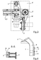
- Figur 3
- eine Detaildarstellung aus
Figur 2 im Bereich eines der am Drehgestell angeordneten Mitnehmeranschläge, - Figur 4
- eine separate Seitenansicht sowie ein Schnitt A - A eines Mitnehmeranschlags samt der erfindungsgemäßen Federanordnung.
- FIG. 1
- a perspective view of a brake frame, which is arranged raised and lowered on a bogie of a rail vehicle,
- FIG. 2
- a top view of the brake frame of Figure 1 with emphasis on the areas that interact with Mitnehmeranschlägen the bogie,
- FIG. 3
- 2 shows a detail of FIG. 2 in the region of one of the driver stops arranged on the bogie,
- FIG. 4
- a separate side view and a section A - A of a Mitnehmeranschlags together with the spring arrangement according to the invention.
Ein Bremsrahmen besteht gemäß Figur 1 im wesentlichen aus zwei parallel in Spurbreite
beabstandet angeordneten Magnetträgem 1a und 1b, die gemeinsam mit einer aus zwei Spurhaltern
2a und 2b bestehenden Spurhalteranordnung in Form eines Rechtecks zusammengesetzt
sind. Der Spurhalter 2a und 2b und die Magnetträger 1a und 1b bestehen aus Stahlprofilen
sind zur Bildung des Bremsrahmens miteinander verschraubt. An den beiden Magnetträgern
1a und 1b ist je ein elektrischer Bremsmagnet 3a und 3b befestigt. Zum Bremsen wirken
die Bremsmagneten 3a und 3b mit je einer zugeordneten Schiene 4 des Gleises (hier symbolisch
angedeutet) zusammen. Bei Absenken der bestromten Bremsmagnete 3a und 3b in
Richtung der zugeordneten Schiene setzt aufgrund der hierbei entstehenden Magnetkraft die
Bremswirkung für das sich relativ zum Gleis bewegende Schienenfahrzeug ein. Zum Absenken
der Bremsmagnete 3a und 3b dienen in den Eckbereichen des Bremsrahmens angeordnete
druckmittelbeaufschlagbare Betätigungszylinder 5, mit denen der gesamte Bremsrahmen
samt Bremsmagnete 3a und 3b relativ zum Drehgestell 6 des hier nicht weiter dargestellten
Schienenfahrzeuges vertikal bewegbar sind. Im angehobenen Zustand, d.h. in der Lösestellung
der Magnetbremse, ist der Bremsrahmen über eine ebenfalls je in den Eckbereichen des
Bremsrahmens angeordnete Zentriereinrichtung 7 am Drehgestell arretierbar. Die Arretierung
erfolgt dabei durch ein formschlüssiges Zusammenwirken der Zentriereinrichtung 7 mit korrespondierend
hierzu ausgebildeten konstruktiven Mitteln am Drehgestell 6.A brake frame consists of Figure 1 essentially of two parallel track width
spaced apart
Wie gemäß Figur 2 in der Draufsicht auf den Bremsrahmen zu erkennen ist, sind seitens des
Drehgestells 6 (Strichpunktlinie) insgesamt vier Mitnehmeranschläge 8a, 8b, 8c, 8d vorgesehen,
die in den Eckbereichen des rechteckförmigen Bremsrahmens endseitig mit den Spurhaltern
2a und 2b korrespondieren. Dabei sind die Mitnehmeranschläge 8a bis 8d gegenüber
dem Bremsrahmen unter Wahrung eines an späterer Stelle eingehender erläuterten Längs-
und Querspiels angeordnet, um die vertikale Bewegbarkeit des Bremsrahmens sowie dessen
Führung zu ermöglichen. Die Mitnehmeranschläge 8a, 8b, 8c, 8d sind rahmeninnenseitig
derart plaziert, daß sie in beide Fahrtrichtungen wirken können. In der einen Fahrtrichtung
kommen dabei die Mitnehmeranschläge 8a und 8b am Bremsrahmen zur Anlage; in der
anderen Fahrtrichtung dagegen die Mitnehmeranschläge 8c und 8d.As can be seen in Figure 2 in the plan view of the brake frame are on the part of the
Bogie 6 (dotted line) a total of four driver stops 8a, 8b, 8c, 8d provided
in the corners of the rectangular brake frame end with the
Gemäß Figur 3 weist der am Drehgestell 6 (Strichpunktlinie) angebrachte Mitnehmeranschlag
8 einen statisch stabilen kastenförmigen Querschnitt auf. Eine Anschlagfläche 9 des
Mitnehmeranschlags 8 ist gegenüberliegend eines korrespondierenden Anschlagbereichs 10
endseitig des Spurhalters 2 angeordnet. Hierüber erfolgt die Bremskraftübertragung vom
Bremsrahmen auf das Drehgestell 6. Im unbelasteten Zustand besteht ein Querspiel zwischen
dem Mitnehmeranschlag 8 und derjenigen vertikal abgewinkelten Teilfläche des Anschlagbereichs
10, die parallel zur Bewegungsebene des Magnetträgers 1 verläuft. Ein Längsspiel
besteht im unbelasteten Zustand zwischen der in der Bewegungsebene des Spurhalters 2 angeordneten
Teilfläche des Anschlagbereichs 10 und der Anschlagfläche 9 des Mitnehmeranschlags
8. Das Längs- und Querspiel dient dem Ausgleich von geringen relativen Verschiebungen
zwischen dem Bremsrahmen und dem Drehgestell 6, die aufgrund des Zusammenwirkens
der Bremsmagnete 3 mit dem Gleis während der Bremsbetriebes auftreten und gewährleisten
eine geführte vertikale Bewegbarkeit des Bremsrahmens.According to FIG. 3, the driver stop attached to the bogie 6 (dot-dash line)
8 a statically stable box-shaped cross section. An
In der Figur 4 ist der am Drehgestell 6 angebrachte Mitnehmeranschlag 8 einzeln dargestellt.
Der sich vom Drehgestell 6 in vertikaler Richtung nach unten erstreckende Mitnehmeranschlag
8 besteht, wie der Schnitt A - A zeigt, aus vier Flachstahlprofilteilen die durch
Schweißen zu der kastenförmigen Anordnung verbunden sind. Zur Minimierung der Belastung
des hier nicht gezeigten Bremsrahmens während der Übertragung der Bremskräfte auf
das Drehgestell 6 ist auf der endseitig am Mitnehmeranschlag 8 angeordneten Anschlagfläche
9 eine Federanordnung 11 befestigt. Die Federanordnung 11 ist hier in Form eines plattenartig
ausgebildeten Gummielements ausgeführt. Hierauf ist wiederum eine Verschleißplatte
12 aus einer verschleißfesten Mn-Stahllegierung befestigt. Während der im Bremsbetrieb
festen Anlage der Verschleißplatte 12 an dem hier nicht gezeigten korrespondierenden Anschlagbereich
des Bremsrahmens bildet sich durch die Federwirkung der Federanordnung 11
eine in Längs- und Querrichtung elastische Kopplungsstelle, so daß der Bremsrahmen
während des Bremsbetriebes eine stets belastungsoptimale Position einnehmen kann.In the figure 4 attached to the
Die Erfindung ist nicht beschränkt auf das vorstehend beschriebene bevorzugte Ausführungsbeispiel. Es sind vielmehr auch konstruktive Abwandlungen hiervon denkbar, die selbst bei anders gearteter Ausgestaltung in den von der Erfindung beanspruchten Schutzbereich eingreifen. So ist die Erfindung insbesondere nicht auf die Verwendung eines Elastomerkörpers als Federanordnung beschränkt. Diese kann ebenso beispielsweise aus einer aus Federstahl hergestellten Federanordnung bestehen, wobei über die Formgebung des Federstahls die erforderliche Feaersteifigkeit je nach Einsatzfall anpaßbar ist. Weiterhin ist die Gestalt des Bremsrahmens nicht auf eine rechteckförmige Anordnung beschränkt. Eine andere Anordnung ist ebenso denkbar, die unter Wahrung des Spurbreitenabstandes eine synchrone vertikale Bewegbarkeit der Bremsmagnete sicherstellt. The invention is not limited to the preferred embodiment described above. Rather, constructive modifications thereof are conceivable, even at engage differently embodiment in the claimed by the invention scope. Thus, the invention is not particularly concerned with the use of an elastomeric body limited as a spring arrangement. This can also, for example, from a spring steel made spring assembly, wherein on the shape of the spring steel, the required Feaersteifigkeit is adaptable depending on the application. Furthermore, the shape of the Brake frame is not limited to a rectangular arrangement. Another arrangement is also conceivable, while maintaining the track pitch a synchronous vertical Mobility of the brake magnets ensures.
- 11
- Magnetträgermagnet carrier
- 22
- SpurhalterAnchor arm
- 33
- Bremsmagnetbrake magnet
- 44
- Schienerail
- 55
- Betätigungszylinderactuating cylinder
- 66
- Drehgestellbogie
- 77
- Zentriereinrichtungcentering
- 88th
- Mitnehmeranschlagdriver stop
- 99
- Anschlagflächestop surface
- 1010
- Anschlagbereichstop area
- 1111
- Federanordnungspring assembly
- 1212
- Verschleißplattewear plate
Claims (10)
- Device for mechanically coupling a track brake to a bogie (6) of a rail vehicle, which track brake includes electrical braking solenoids (3a, 3b) associated with a respective rail (4) of the track, which are each so disposed on a respective solenoid support (1a, 1b) that they can be raised and lowered relative to the associated rail (4), with a rail brace system being provided in this device, which indudes a brake frame constituted by said solenoid supports (1a, 1b) and rail braces (2a, 2b), which brake frame serves to hold said braking solenoids within the track width, wherein moreover several driving dogs (8a à 8d) are provided on said bogie (6), which are operative along and across the direction of travel, which driving dogs cooperate to transmit the braking force by means of corresponding bearing zones (10) that are provided on said brake frame,
characterised in that a wearing plate (12) made of a hard material is connected via a spring system (11) to a bearing surface (9) of said driving dog (8) or to the bearing zone (10) on the side of said brake frame so as to form a resilient coupling site operative along the longitudinal and the transverse directions. - Device according to Claim 1, characterised in that said spring system (11) is made of an elastomer material configured in the form of a plate.
- Device according to Claim 2, characterised in that said spring system (11) with said wearing plate (12) is designed in the form of a rubber/metal part.
- Device according to Claim 1, characterised in that said spring system (11) is constituted by at least one compression spring made of spring steel.
- Device according to Claim 5, characterised in that said metal compression spring is designed in the manner of a spiral spring, a leaf spring or a disk spring.
- Device according to Claim 1, characterised in that said wearing plate (12) is made of a hard steel alloy containing a manganese fraction.
- Device according to Claim 1, characterised in that said wearing plate (12) is made of a brass alloy.
- Device according to Claim 1, characterised in that said rail brace system comprises two parallel rail braces (2a, 2b) arranged at a mutual spacing, which, jointly with said solenoid supports (1a, 1 b), constitute a rectangular brake frame.
- Device according to Claim 7, characterised in that four driving dogs (8a, 8b, 8c, 8d) are provided altogether, which bear against said rail brace system by the corner areas of said rectangular brake frame on the terminal side, with said driving dogs (8a to 8d) being arranged in opposition to said brake frame so as to maintain a longitudinal and lateral traverse.
- Device according to Claim 1, characterised in that said electrical braking solenoids (3a, 3b) are raised and lowered via actuating cylinders (5) disposed on the terminal side on said solenoid support (1a, 1 b) and adapted to be acted upon by a compressed medium, wherein the braking position is assumed by lowering said braking solenoids (3a, 3b) and wherein, in the brake release position, said braking solenoids (3a, 3b) cooperate positively with a centring means (7) for locking.
Priority Applications (1)
| Application Number | Priority Date | Filing Date | Title |
|---|---|---|---|
| DK01969656T DK1315647T3 (en) | 2000-08-28 | 2001-08-28 | Device for mechanical coupling of a rail brake on a bogie to a rail vehicle (brake force carrier) |
Applications Claiming Priority (3)
| Application Number | Priority Date | Filing Date | Title |
|---|---|---|---|
| DE10042213A DE10042213A1 (en) | 2000-08-28 | 2000-08-28 | Device for mechanically coupling a rail brake to a bogie of a rail vehicle (brake force driver) |
| DE10042213 | 2000-08-28 | ||
| PCT/EP2001/009887 WO2002018190A2 (en) | 2000-08-28 | 2001-08-28 | Device for mechanically coupling a rail brake on a steering bogie of a rail vehicle (brake power driver) |
Publications (2)
| Publication Number | Publication Date |
|---|---|
| EP1315647A2 EP1315647A2 (en) | 2003-06-04 |
| EP1315647B1 true EP1315647B1 (en) | 2005-06-15 |
Family
ID=7654048
Family Applications (1)
| Application Number | Title | Priority Date | Filing Date |
|---|---|---|---|
| EP01969656A Expired - Lifetime EP1315647B1 (en) | 2000-08-28 | 2001-08-28 | Device for mechanically coupling a rail brake on a steering bogie of a rail vehicle (brake power driver) |
Country Status (8)
| Country | Link |
|---|---|
| EP (1) | EP1315647B1 (en) |
| AT (1) | ATE297860T1 (en) |
| DE (2) | DE10042213A1 (en) |
| ES (1) | ES2243550T3 (en) |
| HU (1) | HU228163B1 (en) |
| NO (1) | NO328451B1 (en) |
| PT (1) | PT1315647E (en) |
| WO (1) | WO2002018190A2 (en) |
Families Citing this family (3)
| Publication number | Priority date | Publication date | Assignee | Title |
|---|---|---|---|---|
| CN102431571B (en) * | 2011-10-24 | 2014-04-16 | 南车株洲电力机车有限公司 | Connecting device of magnetic track brake and magnetic track brake apparatus |
| DE202021103772U1 (en) * | 2021-07-14 | 2022-10-27 | Faiveley Transport Bochum GmbH | Running gear for a rail vehicle with a magnetic track brake and a centering device, magnetic track brake and centering device |
| CN117962952B (en) * | 2024-02-23 | 2024-08-06 | 中南大学 | Suspension mechanism of magnetic track brake and magnetic track brake |
Family Cites Families (5)
| Publication number | Priority date | Publication date | Assignee | Title |
|---|---|---|---|---|
| DE883293C (en) * | 1951-09-16 | 1953-07-16 | Strassenbahnen Hannover Ag | Spring suspension for rail brake magnets |
| US2782873A (en) * | 1952-07-31 | 1957-02-26 | Eksjoverkan Ab | Device in electrical rail brakes |
| DE2418636A1 (en) * | 1974-04-18 | 1975-10-30 | Knorr Bremse Gmbh | CENTERING DEVICE FOR RAIL BRAKE MAGNETS |
| FR2314852A1 (en) * | 1975-06-18 | 1977-01-14 | Sncf | Suspension for linear eddy current brakes - uses slide guidance to connect brake carrier and bogie frame |
| DE19732483A1 (en) * | 1997-07-29 | 1999-02-04 | Sab Wabco Bsi Verkehrstechnik | Magnetic braking device for rail vehicles |
-
2000
- 2000-08-28 DE DE10042213A patent/DE10042213A1/en not_active Withdrawn
-
2001
- 2001-08-28 ES ES01969656T patent/ES2243550T3/en not_active Expired - Lifetime
- 2001-08-28 HU HU0300795A patent/HU228163B1/en not_active IP Right Cessation
- 2001-08-28 PT PT01969656T patent/PT1315647E/en unknown
- 2001-08-28 EP EP01969656A patent/EP1315647B1/en not_active Expired - Lifetime
- 2001-08-28 DE DE50106535T patent/DE50106535D1/en not_active Expired - Lifetime
- 2001-08-28 WO PCT/EP2001/009887 patent/WO2002018190A2/en active IP Right Grant
- 2001-08-28 AT AT01969656T patent/ATE297860T1/en active
-
2003
- 2003-02-26 NO NO20030904A patent/NO328451B1/en not_active IP Right Cessation
Also Published As
| Publication number | Publication date |
|---|---|
| WO2002018190A2 (en) | 2002-03-07 |
| DE10042213A1 (en) | 2002-03-21 |
| EP1315647A2 (en) | 2003-06-04 |
| ES2243550T3 (en) | 2005-12-01 |
| DE50106535D1 (en) | 2005-07-21 |
| WO2002018190A3 (en) | 2002-05-23 |
| NO328451B1 (en) | 2010-02-22 |
| NO20030904D0 (en) | 2003-02-26 |
| HUP0300795A2 (en) | 2003-07-28 |
| ATE297860T1 (en) | 2005-07-15 |
| PT1315647E (en) | 2005-10-31 |
| HU228163B1 (en) | 2013-01-28 |
Similar Documents
| Publication | Publication Date | Title |
|---|---|---|
| EP3253637B1 (en) | Transportation device for rail vehicles | |
| DE112013001207B4 (en) | Railway bogie with balancing device attached to the axle | |
| EP1315647B1 (en) | Device for mechanically coupling a rail brake on a steering bogie of a rail vehicle (brake power driver) | |
| DE2460159C3 (en) | Running gear for rail vehicles, in particular for mobile track machines | |
| EP3554914B1 (en) | Transport device | |
| WO2022144393A1 (en) | Levitation frame, vehicle, rail arrangement and magnetic levitation railway | |
| EP1897777B1 (en) | Bogie | |
| EP0282796A1 (en) | Point for switches or crossings | |
| EP3245114A1 (en) | Rail vehicle, in particular a locomotive | |
| EP3042099B1 (en) | Secondary spring having an integrated transverse stop | |
| EP0684204A2 (en) | Vertical lift | |
| EP1897776B1 (en) | Bogie | |
| EP2551167A2 (en) | Load-dependent spring assembly | |
| EP3655304B1 (en) | Magnetic brake for a rail vehicle with elongated legs of the magnet elements | |
| WO2022144390A1 (en) | Levitation frame for a track-bound levitation vehicle of a maglev track | |
| EP0284928B1 (en) | Rail track centering apparatus for raising and lowering station in electric suspended track | |
| EP0299318B1 (en) | Undercarriage for railway vehicles with magnetic track brake or eddy current brake | |
| DE19503381C2 (en) | Suspension of a rail brake on a bogie of a rail vehicle | |
| EP0724997A1 (en) | Suspension of a track brake, especially an eddy current brake on a bagie of a rail vehicle | |
| EP1447297A1 (en) | Coupling bar adjustable in length, with centralisation function. | |
| DE60310112T2 (en) | MAGNETIC TRACK BRAKE | |
| AT228263B (en) | Weighless bogie | |
| DE3840755C2 (en) | ||
| DE233212C (en) | ||
| DE102015119928A1 (en) | sledgehammer |
Legal Events
| Date | Code | Title | Description |
|---|---|---|---|
| PUAI | Public reference made under article 153(3) epc to a published international application that has entered the european phase |
Free format text: ORIGINAL CODE: 0009012 |
|
| 17P | Request for examination filed |
Effective date: 20030328 |
|
| AK | Designated contracting states |
Designated state(s): AT BE CH CY DE DK ES FI FR GB GR IE IT LI LU MC NL PT SE TR |
|
| RIN1 | Information on inventor provided before grant (corrected) |
Inventor name: FRIEDL, ANDREAS Inventor name: SCHMIED, LOTHAR Inventor name: LEHMANN, HENRY |
|
| GRAP | Despatch of communication of intention to grant a patent |
Free format text: ORIGINAL CODE: EPIDOSNIGR1 |
|
| GRAS | Grant fee paid |
Free format text: ORIGINAL CODE: EPIDOSNIGR3 |
|
| GRAA | (expected) grant |
Free format text: ORIGINAL CODE: 0009210 |
|
| AK | Designated contracting states |
Kind code of ref document: B1 Designated state(s): AT BE CH CY DE DK ES FI FR GB GR IE IT LI LU MC NL PT SE TR |
|
| PG25 | Lapsed in a contracting state [announced via postgrant information from national office to epo] |
Ref country code: IE Free format text: LAPSE BECAUSE OF FAILURE TO SUBMIT A TRANSLATION OF THE DESCRIPTION OR TO PAY THE FEE WITHIN THE PRESCRIBED TIME-LIMIT Effective date: 20050615 Ref country code: TR Free format text: LAPSE BECAUSE OF FAILURE TO SUBMIT A TRANSLATION OF THE DESCRIPTION OR TO PAY THE FEE WITHIN THE PRESCRIBED TIME-LIMIT Effective date: 20050615 Ref country code: GB Free format text: LAPSE BECAUSE OF FAILURE TO SUBMIT A TRANSLATION OF THE DESCRIPTION OR TO PAY THE FEE WITHIN THE PRESCRIBED TIME-LIMIT Effective date: 20050615 |
|
| REG | Reference to a national code |
Ref country code: GB Ref legal event code: FG4D Free format text: NOT ENGLISH Ref country code: CH Ref legal event code: EP |
|
| REG | Reference to a national code |
Ref country code: CH Ref legal event code: NV Representative=s name: ISLER & PEDRAZZINI AG |
|
| REF | Corresponds to: |
Ref document number: 50106535 Country of ref document: DE Date of ref document: 20050721 Kind code of ref document: P |
|
| REG | Reference to a national code |
Ref country code: IE Ref legal event code: FG4D Free format text: LANGUAGE OF EP DOCUMENT: GERMAN |
|
| REG | Reference to a national code |
Ref country code: DK Ref legal event code: T3 |
|
| PG25 | Lapsed in a contracting state [announced via postgrant information from national office to epo] |
Ref country code: CY Free format text: LAPSE BECAUSE OF FAILURE TO SUBMIT A TRANSLATION OF THE DESCRIPTION OR TO PAY THE FEE WITHIN THE PRESCRIBED TIME-LIMIT Effective date: 20050828 |
|
| PG25 | Lapsed in a contracting state [announced via postgrant information from national office to epo] |
Ref country code: MC Free format text: LAPSE BECAUSE OF NON-PAYMENT OF DUE FEES Effective date: 20050831 Ref country code: LU Free format text: LAPSE BECAUSE OF NON-PAYMENT OF DUE FEES Effective date: 20050831 |
|
| REG | Reference to a national code |
Ref country code: GR Ref legal event code: EP Ref document number: 20050402487 Country of ref document: GR Ref country code: SE Ref legal event code: TRGR |
|
| REG | Reference to a national code |
Ref country code: PT Ref legal event code: SC4A Effective date: 20050901 |
|
| REG | Reference to a national code |
Ref country code: ES Ref legal event code: FG2A Ref document number: 2243550 Country of ref document: ES Kind code of ref document: T3 |
|
| GBV | Gb: ep patent (uk) treated as always having been void in accordance with gb section 77(7)/1977 [no translation filed] |
Effective date: 20050615 |
|
| REG | Reference to a national code |
Ref country code: IE Ref legal event code: FD4D |
|
| ET | Fr: translation filed | ||
| PLBE | No opposition filed within time limit |
Free format text: ORIGINAL CODE: 0009261 |
|
| STAA | Information on the status of an ep patent application or granted ep patent |
Free format text: STATUS: NO OPPOSITION FILED WITHIN TIME LIMIT |
|
| 26N | No opposition filed |
Effective date: 20060316 |
|
| REG | Reference to a national code |
Ref country code: CH Ref legal event code: PCAR Free format text: ISLER & PEDRAZZINI AG;POSTFACH 1772;8027 ZUERICH (CH) |
|
| PGFP | Annual fee paid to national office [announced via postgrant information from national office to epo] |
Ref country code: GR Payment date: 20140820 Year of fee payment: 14 |
|
| PGFP | Annual fee paid to national office [announced via postgrant information from national office to epo] |
Ref country code: PT Payment date: 20140228 Year of fee payment: 14 Ref country code: IT Payment date: 20140828 Year of fee payment: 14 |
|
| REG | Reference to a national code |
Ref country code: FR Ref legal event code: PLFP Year of fee payment: 15 |
|
| PGFP | Annual fee paid to national office [announced via postgrant information from national office to epo] |
Ref country code: NL Payment date: 20150824 Year of fee payment: 15 |
|
| PGFP | Annual fee paid to national office [announced via postgrant information from national office to epo] |
Ref country code: DE Payment date: 20150820 Year of fee payment: 15 Ref country code: DK Payment date: 20150825 Year of fee payment: 15 Ref country code: ES Payment date: 20150825 Year of fee payment: 15 Ref country code: FI Payment date: 20150820 Year of fee payment: 15 Ref country code: CH Payment date: 20150824 Year of fee payment: 15 |
|
| PGFP | Annual fee paid to national office [announced via postgrant information from national office to epo] |
Ref country code: FR Payment date: 20150824 Year of fee payment: 15 Ref country code: AT Payment date: 20150820 Year of fee payment: 15 Ref country code: BE Payment date: 20150820 Year of fee payment: 15 Ref country code: SE Payment date: 20150824 Year of fee payment: 15 |
|
| REG | Reference to a national code |
Ref country code: PT Ref legal event code: MM4A Free format text: LAPSE DUE TO NON-PAYMENT OF FEES Effective date: 20160229 |
|
| PG25 | Lapsed in a contracting state [announced via postgrant information from national office to epo] |
Ref country code: IT Free format text: LAPSE BECAUSE OF NON-PAYMENT OF DUE FEES Effective date: 20150828 |
|
| PG25 | Lapsed in a contracting state [announced via postgrant information from national office to epo] |
Ref country code: PT Free format text: LAPSE BECAUSE OF NON-PAYMENT OF DUE FEES Effective date: 20160229 Ref country code: GR Free format text: LAPSE BECAUSE OF NON-PAYMENT OF DUE FEES Effective date: 20160303 |
|
| REG | Reference to a national code |
Ref country code: GR Ref legal event code: ML Ref document number: 20050402487 Country of ref document: GR Effective date: 20160303 |
|
| PG25 | Lapsed in a contracting state [announced via postgrant information from national office to epo] |
Ref country code: BE Free format text: LAPSE BECAUSE OF NON-PAYMENT OF DUE FEES Effective date: 20160831 |
|
| REG | Reference to a national code |
Ref country code: DE Ref legal event code: R119 Ref document number: 50106535 Country of ref document: DE |
|
| REG | Reference to a national code |
Ref country code: DK Ref legal event code: EBP Effective date: 20160831 |
|
| REG | Reference to a national code |
Ref country code: SE Ref legal event code: EUG |
|
| REG | Reference to a national code |
Ref country code: CH Ref legal event code: PL |
|
| REG | Reference to a national code |
Ref country code: NL Ref legal event code: MM Effective date: 20160901 |
|
| REG | Reference to a national code |
Ref country code: AT Ref legal event code: MM01 Ref document number: 297860 Country of ref document: AT Kind code of ref document: T Effective date: 20160828 |
|
| PG25 | Lapsed in a contracting state [announced via postgrant information from national office to epo] |
Ref country code: FI Free format text: LAPSE BECAUSE OF NON-PAYMENT OF DUE FEES Effective date: 20160828 Ref country code: CH Free format text: LAPSE BECAUSE OF NON-PAYMENT OF DUE FEES Effective date: 20160831 Ref country code: LI Free format text: LAPSE BECAUSE OF NON-PAYMENT OF DUE FEES Effective date: 20160831 Ref country code: SE Free format text: LAPSE BECAUSE OF NON-PAYMENT OF DUE FEES Effective date: 20160829 |
|
| REG | Reference to a national code |
Ref country code: FR Ref legal event code: ST Effective date: 20170428 |
|
| PG25 | Lapsed in a contracting state [announced via postgrant information from national office to epo] |
Ref country code: AT Free format text: LAPSE BECAUSE OF NON-PAYMENT OF DUE FEES Effective date: 20160828 |
|
| PG25 | Lapsed in a contracting state [announced via postgrant information from national office to epo] |
Ref country code: NL Free format text: LAPSE BECAUSE OF NON-PAYMENT OF DUE FEES Effective date: 20160901 |
|
| PG25 | Lapsed in a contracting state [announced via postgrant information from national office to epo] |
Ref country code: FR Free format text: LAPSE BECAUSE OF NON-PAYMENT OF DUE FEES Effective date: 20160831 Ref country code: DK Free format text: LAPSE BECAUSE OF NON-PAYMENT OF DUE FEES Effective date: 20160831 Ref country code: DE Free format text: LAPSE BECAUSE OF NON-PAYMENT OF DUE FEES Effective date: 20170301 |
|
| PG25 | Lapsed in a contracting state [announced via postgrant information from national office to epo] |
Ref country code: ES Free format text: LAPSE BECAUSE OF NON-PAYMENT OF DUE FEES Effective date: 20160829 |
|
| REG | Reference to a national code |
Ref country code: ES Ref legal event code: FD2A Effective date: 20181126 |