EP1315266A2 - Battery charger - Google Patents
Battery charger Download PDFInfo
- Publication number
- EP1315266A2 EP1315266A2 EP02024968A EP02024968A EP1315266A2 EP 1315266 A2 EP1315266 A2 EP 1315266A2 EP 02024968 A EP02024968 A EP 02024968A EP 02024968 A EP02024968 A EP 02024968A EP 1315266 A2 EP1315266 A2 EP 1315266A2
- Authority
- EP
- European Patent Office
- Prior art keywords
- battery
- housing
- charger
- set forth
- supported
- Prior art date
- Legal status (The legal status is an assumption and is not a legal conclusion. Google has not performed a legal analysis and makes no representation as to the accuracy of the status listed.)
- Withdrawn
Links
Images













Classifications
-
- H—ELECTRICITY
- H01—ELECTRIC ELEMENTS
- H01M—PROCESSES OR MEANS, e.g. BATTERIES, FOR THE DIRECT CONVERSION OF CHEMICAL ENERGY INTO ELECTRICAL ENERGY
- H01M50/00—Constructional details or processes of manufacture of the non-active parts of electrochemical cells other than fuel cells, e.g. hybrid cells
- H01M50/20—Mountings; Secondary casings or frames; Racks, modules or packs; Suspension devices; Shock absorbers; Transport or carrying devices; Holders
- H01M50/267—Mountings; Secondary casings or frames; Racks, modules or packs; Suspension devices; Shock absorbers; Transport or carrying devices; Holders having means for adapting to batteries or cells of different types or different sizes
-
- H—ELECTRICITY
- H01—ELECTRIC ELEMENTS
- H01M—PROCESSES OR MEANS, e.g. BATTERIES, FOR THE DIRECT CONVERSION OF CHEMICAL ENERGY INTO ELECTRICAL ENERGY
- H01M50/00—Constructional details or processes of manufacture of the non-active parts of electrochemical cells other than fuel cells, e.g. hybrid cells
- H01M50/20—Mountings; Secondary casings or frames; Racks, modules or packs; Suspension devices; Shock absorbers; Transport or carrying devices; Holders
- H01M50/244—Secondary casings; Racks; Suspension devices; Carrying devices; Holders characterised by their mounting method
-
- H—ELECTRICITY
- H01—ELECTRIC ELEMENTS
- H01M—PROCESSES OR MEANS, e.g. BATTERIES, FOR THE DIRECT CONVERSION OF CHEMICAL ENERGY INTO ELECTRICAL ENERGY
- H01M50/00—Constructional details or processes of manufacture of the non-active parts of electrochemical cells other than fuel cells, e.g. hybrid cells
- H01M50/20—Mountings; Secondary casings or frames; Racks, modules or packs; Suspension devices; Shock absorbers; Transport or carrying devices; Holders
- H01M50/247—Mountings; Secondary casings or frames; Racks, modules or packs; Suspension devices; Shock absorbers; Transport or carrying devices; Holders specially adapted for portable devices, e.g. mobile phones, computers, hand tools or pacemakers
-
- H—ELECTRICITY
- H01—ELECTRIC ELEMENTS
- H01M—PROCESSES OR MEANS, e.g. BATTERIES, FOR THE DIRECT CONVERSION OF CHEMICAL ENERGY INTO ELECTRICAL ENERGY
- H01M50/00—Constructional details or processes of manufacture of the non-active parts of electrochemical cells other than fuel cells, e.g. hybrid cells
- H01M50/20—Mountings; Secondary casings or frames; Racks, modules or packs; Suspension devices; Shock absorbers; Transport or carrying devices; Holders
- H01M50/296—Mountings; Secondary casings or frames; Racks, modules or packs; Suspension devices; Shock absorbers; Transport or carrying devices; Holders characterised by terminals of battery packs
-
- H—ELECTRICITY
- H01—ELECTRIC ELEMENTS
- H01M—PROCESSES OR MEANS, e.g. BATTERIES, FOR THE DIRECT CONVERSION OF CHEMICAL ENERGY INTO ELECTRICAL ENERGY
- H01M10/00—Secondary cells; Manufacture thereof
- H01M10/42—Methods or arrangements for servicing or maintenance of secondary cells or secondary half-cells
-
- H—ELECTRICITY
- H02—GENERATION; CONVERSION OR DISTRIBUTION OF ELECTRIC POWER
- H02J—ELECTRIC POWER NETWORKS; CIRCUIT ARRANGEMENTS OR SYSTEMS FOR SUPPLYING OR DISTRIBUTING ELECTRIC POWER; SYSTEMS FOR STORING ELECTRIC ENERGY
- H02J7/00—Circuit arrangements for charging or discharging batteries or for supplying loads from batteries
- H02J7/70—Circuit arrangements for charging or discharging batteries or for supplying loads from batteries characterised by the mechanical construction
-
- Y—GENERAL TAGGING OF NEW TECHNOLOGICAL DEVELOPMENTS; GENERAL TAGGING OF CROSS-SECTIONAL TECHNOLOGIES SPANNING OVER SEVERAL SECTIONS OF THE IPC; TECHNICAL SUBJECTS COVERED BY FORMER USPC CROSS-REFERENCE ART COLLECTIONS [XRACs] AND DIGESTS
- Y02—TECHNOLOGIES OR APPLICATIONS FOR MITIGATION OR ADAPTATION AGAINST CLIMATE CHANGE
- Y02E—REDUCTION OF GREENHOUSE GAS [GHG] EMISSIONS, RELATED TO ENERGY GENERATION, TRANSMISSION OR DISTRIBUTION
- Y02E60/00—Enabling technologies; Technologies with a potential or indirect contribution to GHG emissions mitigation
- Y02E60/10—Energy storage using batteries
Definitions
- a battery charger typically includes a charger housing and a charging circuit supported by the charger housing that is electrically connectable to a power source.
- a battery is supported by the charger housing and electrically connected to the charging circuit so that power is selectively supplied to the battery to charge the battery.
- the battery is connected to the charging circuit by charger terminals supported on the charger housing.
- Existing battery chargers and their individual components are not suited for heavy-duty usc commonly found at a work site including impacts from falling objects or from the battery charger falling. Also, existing battery chargers and their individual components are not suited for outdoor use including being exposed to weather (i.e. sun, rain, wind, etc.) and other contaminants (i.e. dirt, sand, gravel, mud, sawdust, etc.). Weather and contaminants can damage the components of the battery charger and may render the battery charger inoperable.
- weather i.e. sun, rain, wind, etc.
- other contaminants i.e. dirt, sand, gravel, mud, sawdust, etc.
- the charging terminals are typically exposed to the outside environment. Contaminants (such as dirt, sand, mud, sawdust, etc.) may block the charger terminals and prevent electrical connection between the charger terminals and the battery (and charging circuit) or cause a short circuit of the charging circuit. Also, with existing battery chargers, the charge status indicators are not easily seen in outdoor sunlight.
- Existing battery chargers may employ an inefficient charging routine when charging batteries. Some battery chargers maintain charging even after the battery has reached full charge. Such a routine leads to unnecessary heating of the battery, therefore, decreasing the cycle life of the battery. Other battery chargers terminate charging when a pre-set time limit is reached. This routine can also result in overheating and a decrease in battery cycle life or may result in a battery not being fully charged when the charging routine has terminated.
- Existing multiple-port battery chargers include a single charging circuit for all the multiple ports and for all the batteries being charged such that a failure of any component of the charging circuit renders all of the charging ports inoperable.
- the present invention provides a battery charger which substantially alleviates one or more of the above-described and other problems with existing battery chargers.
- the battery charger is a multiple-port battery charger for charging power tool batteries.
- the battery charger is a heavy-duty battery charger designed to be used outdoors and/or in harsh working conditions.
- the invention provides a battery charger including a housing having an outer surface, a battery being supportable on the outer surface, a charging circuit supported by the housing and electrically connectable to a power source and to the battery, and protective structure connected to and extending from the outer surface of the housing, the protective structure extending from the outer surface beyond the battery.
- the invention provides a battery charger including a housing having an outer surface, a battery being supportable on the outer surface, a charging circuit supported by the housing and electrically connectable to a power source and to the battery, a base connected to the housing for supporting the battery charger on a surface, the base extending beyond the outer surface of the housing and beyond the battery, and a bar connected to the housing at a first end of the housing, the bar extending beyond the outer surface of the housing and beyond the battery.
- the invention provides a battery charger including a housing, a charging circuit supported by the housing and'electrically connectable to a power source and to a battery, a vent defined by the housing, the vent releasing heated air from the housing and impeding entry of contaminants into the housing, the vent causing the heated air to turn downwardly turn through the vent before being released from the housing, and a drain defined by the housing, the drain releasing contaminants from the housing.
- the invention provides a battery charger including a housing, a charging circuit supported by the housing and electrically connectable with a power source, and a battery port connected to the housing and operable to support a battery.
- the battery port includes a charger terminal electrically connectable to the charging circuit to electrically connect the battery to the charging circuit, a charger terminal support defining an opening, the terminal being supported in the opening, and a charger terminal cover supported by the battery port, the terminal cover closing the opening when the battery is not supported by the battery port.
- the invention provides a battery charger including a housing, a charging circuit supported by the housing and electrically connectable to a power source and a battery, an LED positioned at least partially outside of the housing and electrically connected to the charging circuit, the LED being operable to display a charge status of the battery, and a translucent cover connected to the housing and at least partially enclosing the LED.
- the invention provides a battery charger including a charging routine having a temperature rate termination technique.
- This charging routine is designed to function with, for example, Nickel-Metal Hydride (NiMH), Nickel-Cadmium (NiCd), Lithium-ion (Li-ion) etc. battery cells and includes a maintenance routine and boost routine that follows the normal charge execution.
- the invention provides a multiple-port battery charger including a separate and dedicated charging circuit for each charging port. This configuration allows the remaining charging circuits to be operable if one charging circuit should fail.
- the heavy-duty construction of the battery charger allows the battery charger and its components to withstand impacts after falling several feet or being impacted by other objects, in addition to protecting an attached battery from jarring loose as a result of the impact.
- the contaminant-resistant air vents prevent any liquid or solid contaminants from entering the charger housing. Also, a series of drains are incorporated within the charger to purge any contaminant that may enter the housing, and the suspended charging circuits are kept out of contact from such contaminants.
- the terminal cover prevents any contaminants from contacting the charger terminals when a battery is not connected with the battery charger.
- the cover also provides a sweeping action to keep clean the interconnection between the charging terminals and the battery.
- the LED charge status indicators are bright enough to see in the outdoor sunlight and are viewable from a long distance about a wide range of viewing angles.
- the temperature rate termination technique of the charging routine reduces charge time by several minutes, reduces heat due to charging, and/or increases the cycle life of the battery.
- the independent charging circuits provide the user increased reliability such that a failure of one charging circuit does not result in a complete failure of the multiple port battery charger.
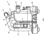
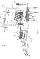
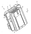
- FIGS. 1-11 A battery charger 10 embodying aspects of the invention is illustrated in FIGS. 1-11.
- the battery charger 10 is constructed for heavy-duty use in a harsh working. environment (for electrical equipment) such as outdoor construction sites, machine shops, manufacturing floors, etc.
- the charger 10 is operable to support and charge batteries 14, such as, for example, 12V, 14.4V, 18V or similar power tool or other equipment batteries 14 of various chemistries (NiCd, NiMH, Li-ion, etc.).
- the batteries 14 include a top surface 16a, a bottom surface 16b, a front surface 16c and two side surfaces 16d to define a generally rectangular shape.
- the batteries 14 may define any number of shapes.
- the charger 10 includes a housing 18 manufactured of a plastic material as a two-piece design.
- a first shell 22 is connected to a second shell 26 to form a cavity 30 therebetween.
- a tongue 34 and a groove 38 are utilized to mate the two shells 22, 26, and an o-ring 42 is positioned between the two shells 22, 26 to seal the interface between the two shells 22, 26.
- the two shells 22, 26 are also molded to define a low spot 46 at the bottom of the housing 18 when the shells 22, 26 are mated.
- a drain 50 is positioned in the low spot 46 to release any contaminant (i.e. dirt, sand, gravel, sawdust, metal shavings, water, oil, grease, etc.) that may enter the cavity 30.
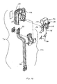
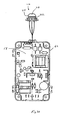
- charging circuits 58 are supported by suspended and cushioned mounting boards 62 housed within the cavity 30.
- the mounting boards 62 are made of a flame-retardant material, such as a V ⁇ -rated plastic.
- the charging circuits 58 and the mounting boards 62 are formed as an assembly, and the charging circuits 58 are potted in the flame retardant material to seal and insulate the components of the charging circuits 58.
- the components of the charging circuits 58 are supported on the mounting boards 62 with required spacing, sealing and insulation to meet UL requirements.
- the cushioned mounting configuration of the mounting boards 62 protects the charging circuits 58 during an impact.
- Such cushioning may be provided by any elastically deformable material (not -shown), such as, for example, rubber washers, positioned between the board 62 and housing 18.
- This mounting configuration also helps minimize exposure of the charging circuits 58 to any contaminant (e.g. dirt, sand, gravel, sawdust, metal shavings, water, oil, grease, etc.) that may enter the cavity 30.
- any contaminant e.g. dirt, sand, gravel, sawdust, metal shavings, water, oil, grease, etc.
- Any contaminant entering the cavity 30 will come to rest along an interior wall or adjacent walls of the housing 18, depending on the orientation of the housing 18. Therefore, with the charging circuits 58 suspended in the middle of the housing 18, it is unlikely any contaminants will contact or come to rest on the charging circuits 58.
- the charging circuits 58 are connectable to a power source (not shown), such as an AC power source through a power cord 64, or a DC power source.
- a power source such as an AC power source through a power cord 64, or a DC power source.
- Charger terminals 66 on battery ports 70 connect the battery 14 to the charging circuit 58.
- the charger 10 utilizes a separate arid dedicated charging circuit 58 for each battery port 70. With this configuration, if one charging circuit 58 fails, the remaining charging circuits 58 will be operable, and the charger 10 will not be rendered totally inoperable.
- Each charging circuit 58 may be similar to the charging circuit described in U.S. Patent No. 6,222,343, issued April 24, 2001, and U.S. Patent Application Serial No. 09/672,620, filed September 29, 2000, now U.S. Patent No. 6,456,035, issued September 24, 2002, which are hereby incorporated by reference.
- air vents 74 are defined in the lower part of the first shell 22, and air vents 78 are defined in the upper part of the second shell 26.
- the air vents 74, 78 include ascending and stepped passageways 82 into the cavity 30.
- Structure defining each passageway 82 includes an outer lip 84, a spacer portion 86, which may have a substantially flat surface, and an inner lip 90 toward the end of the portion 86. This structure helps to prevent any solid (i.e. dirt, sand, sawdust, metal shavings, etc.) or liquid (i.e. water, oil, grease, etc.) contaminants from entering the cavity 30.
- the outer lip 84 will deflect contaminants.
- the structure of the air vents 74, 78 requires any contaminant to first penetrate the exterior of the housing 18, move along the substantially flat surface of the portion 86, and then ascend past the level defined by the inner lip 90. This tortuous path prevents unforced entry of any solid or liquid contaminants into the housing 18. However, if contaminants were to enter the cavity 30, such contaminants would be released through the drain 50.
- heat is generated by the charging circuits 58.
- cooling air is drawn through the air vents 74 into the cavity 30 and flows across, the heated charging circuits 58.
- the cooling air is heated by the charging circuits 58, causing the heated air to rise and escape the cavity 30 through the air vents 78.
- the charger 10 may utilize electrically operated fans to cool the heated charging circuits 58 rather than unforced convection through air vents 74, 78.
- heat removal elements such as, for example, heat sinks, heat pipes, etc. may be incorporated into the battery charger 10 to draw heat from the charging circuits 58.
- the housing 18 is mounted to a base 94 which is designed to buffer and cushion the housing 18 along the edges of the base 94.
- the base 94 is blow molded from a high density polyethylene (HDPE) which is a very strong and impact-resistant material. This material selection allows the base 94 to more effectively absorb the energy associated with an impact.
- uniform wall thickness of about 0.100" around the base 94 prevents its collapse (especially near the corners) when the base 94 is impacted after a fall or some other impacting event.
- the base 94 also includes a drain 98 positioned at a low spot 102 molded into the base 94.
- the drain 50 in the housing 18 and the drain 98 in the base 94 are in fluid communication but are offset from each other so that direct access to the cavity 30 through the drains 50, 98 is inhibited.
- the drain 98 extends through the base 94 so that any contaminant that enters the battery charger 10 can be released.
- a handle 106 is connected to both the housing 18 and the base 94.
- the handle 106 is generally positioned towards the front of the charger 10 where the battery 14 attaches to the battery port 70.
- the handle 106 includes upper portions 110 connected to the housing 18 through impact-absorbing bumpers 114 and lower portions 118 connected to the base 94.
- the bumpers 114 are designed to both absorb and dampen impact energy.
- the bumpers 114 are made of an elastomeric material, such as polyurethane or natural rubber, with both spring and damping characteristics which allows this to happen.
- the bumpers 114 include channels 120 defined therein. The channels 120 extend around the perimeter of the bumpers 114, and allow the bumpers 114 to more easily compress upon being impacted.
- An ergonomic grip 122 is centrally positioned on the handle 106 to provide a comfortable, sure and steady grip on the handle 106.
- the grip 122 may include an elastic, non-slip material covering to provide comfort while the battery charger 10 is carried.
- the handle 106 is made of two halves connected by the grip 122.
- the handle 106 may be made of a single component, such as, for example, a bar, having the grip 122 overmolded or integrally formed with the handle 106.
- the handle 106 allows the user to carry the battery charger 10 to and from a work site, with of without batteries 14 connected to the battery charger 10.
- an attached battery 14 is generally encompassed by a boundary defined by the base 94 and handle 106.
- the handle 106 also functions as a "roll bar,” or protective structure. More particularly, the lower portions 118 of the handle 106 protect the front surface 16c of the battery 14 from being impacted by an object or surface wider than the distance between the lower portions 118 of the handle 106. Similarly, the lower portions 118 protect the side surfaces 16d from being impacted by an object or surface wider than the distance between the housing 18 and the lower portions 118.
- the base 94 protects the bottom surface 16b of the battery 14 from being impacted during a fall or other impacting event.
- the upper portion 110 may provide some protection to the top surface 16a of the battery 14 from being impacted by an object or surface wider than the distance defined by the upper portion 110.
- an additional top cover (not shown) may be provided to protect the top surface 16a of the battery 14.
- the handle 106 and the base 94 protects stored batteries 14 on the charger 10 from impacts.
- the bar-like handle 106 provides protective structure of the charger 10.
- the protective structure may include a solid wall that may extend from the outer surface of the housing 18 and surround surfaces of the batteries 14 to recess the batteries 14 into the wall, while allowing access to the batteries 14.
- a cover or multiple covers may enclose or partially enclose the batteries 14 to protect them from impact.
- the cover or multiple covers may be removable/retractable manually or with insertion of the battery 14.
- the bumpers 114 also absorb some of the energy upon impact, thereby decreasing the chance of jarring loose an attached battery 14 and decreasing the chance of breaking the charger 10 or components of the charger 10.
- rear bumpers 126 and side bumpers 130 are also utilized to help protect the rear and sides of the housing 18, respectively.
- the rear and side bumpers 126, 130 are shown as a one-piece construction that is fastened to the housing 18.
- the rear and side bumpers 126, 130 are made of an impact-resistant and energy absorbing material, such as HDPE.
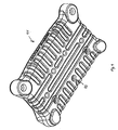
- each battery port 70 includes a battery mounting portion 138, a terminal assembly 142, and a mounting portion 146.
- the battery mounting portion 138 includes battery port projections 150 to guide the battery 14 as the battery 14 engages with the port 70.
- the battery port projections 150 engage matching battery grooves 154 (shown in FIG. 27) on the battery 14 to provide positive alignment with and support on the port 70.
- battery projections 155 engage matching battery port grooves 156 to provide positive alignment with and support on the port 70.
- a series of charger terminals 66 (part of the terminal assembly 142) are recessed within openings in the terminal supports 158 on the port 70. Electrical leads 162 connect the charging circuits 58 with the terminals 66 of a respective port 70.
- the mounting portion 146 further includes fasteners 166 that connect the port 70 with the housing 18.
- the ports 70 are connected to the housing 18 in a sturdy manner such that if the charger 10 falls with the battery 14 attached, the associated port 70 will not break off the housing 18.
- the battery ports 70 are designed to survive a fall from about at least 4 feet with an attached battery 14 without breaking off the housing 18.
- At least portions of the battery charger 10 through which power is transferred are formed of flame-retardant material, such as V ⁇ rated plastic. These portions may include the charging circuits 58 and the mounting board 62 assembly and the battery ports 70. Because of this, other portions of the housing 18 may be formed of other materials.
- the battery 14 supplies power to the charging circuit 58 to initiate charging. Even with the battery charger 10 connected to a power source, no power is provided at the terminals 66 if the battery 14 is not connected to the terminals 66. Therefore, if the battery 14 is not attached to a port 70, there is zero potential between the terminals 66 of that respective port 70. This helps ensure the charging circuit 58 cannot be shorted out when the battery 14 is not attached to the port 70 and reduces the risk of electrical shock when the battery 14 is not attached.
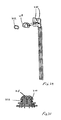
- each battery port 70 also includes a terminal cover 170 that is, in the illustrated construction, spring-biased to cover the terminal support 158.
- the terminal cover 170 includes a hood 174 having a mounting stem 178 on each side.
- a ramp 182 is positioned on each stem 178 between the hood 174 and a pivot 186, at which the cover 170 is attached to the port 70.
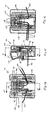
- FIGS. 15 and 20-21 illustrate the cover 170 assembled with the port 70.
- Biasing members such as, in the illustrated construction, torsion springs 190, are positioned between the port 70 and the mounting stems 178 to bias the hood 174 to a covered position over the openings in the terminal supports 158.
- the action of sliding the battery 14 onto the battery mounting portion 138 causes the terminal cover 170 to pivotally retract to uncover the openings in the terminal supports 158 and expose the terminals 66 to the battery 14.
- the battery mounting portion 138 includes an opening 194 through which the ramps 182 project.
- the battery projections 155 engage the ramps 182 upon engaging the battery mounting portion 138.
- the ramps 182 include a slope sufficient to cause the terminal cover 170 to pivot against the biasing force of the springs 190, thereby exposing the terminal supports 158 and the terminals 66 to the battery 14.
- the springs 190 force the cover 170 to pivot back over the terminal supports 158.
- the biasing force is sufficient to close the cover 170 without preventing attachment of the battery 14.
- the terminal cover 170 retracts into the cavity 30 when actuated by battery 14 insertion.
- the cover 170 moves along a path to sweep away contaminants and to clear the interconnection between the port 70 and the battery 14.
- the terminal cover 170 also helps minimize the terminals 66 exposure to the outside environment. When closed, the cover 170 deflects contaminants (i.e. dirt, dust, sand, water, oil, grease, etc.) from adhering to the terminals 66 and adversely affecting the electrical connection between the charging circuit 58 and the battery 14.
- the terminal cover 170 may move in a different manner, such as linearly sliding away from the terminal supports 158, rather than pivoting away from the terminal supports 158 upon the battery 14 engaging the battery mounting portion 138. Also, the terminal cover 170 maybe operable by the user, such as by depressing a button to retract the terminal cover 170.
- a plurality of charge termination protocols including a temperature rate (“TR") termination protocol, and firmware modules, including a trickle module 198, a charge module 202, and an equalization module 206, provide control of battery charging.
- TR temperature rate
- firmware modules including a trickle module 198, a charge module 202, and an equalization module 206
- the TR charge termination protocol monitors the rate of temperature increase of a battery 14 during a charging cycle and terminates the charge flow when the battery 14 reaches a predetermined rate temperature change.
- the TR protocol also accounts for thermal lagging which causes the battery 14 to continue heating after removal of the charging current.
- the TR protocol provides a reduction in battery charge time, a control of heat increase due to charging, and an increase in battery life.
- the firmware executes code that monitors the normal charge cycle of a battery 14.
- the charge cycle may be terminated by the TR termination protocol as previously described, Termination of the normal charge cycle results in execution of code pertaining to the trickle module 198.
- the trickle module 198 is operable to set a "trickle" flag in software that corresponds to termination of the normal charge cycle and initiation of the trickle module 198. Setting the trickle flag initiates the charge module 202 and the equalization module 206.
- the charge module 202 is operable to impose a maintenance charge on the battery 14 whereby a current pulse is applied to the battery 14 for approximately five seconds every two minutes.
- the equalization module 206 executes code that allows the battery 14 to rest and cool for approximately fifteen minutes and sets a time limit for the equalization to occur. If the equalization module 206 does not execute within the time limit, the module terminates and the charge module 202 continues the maintenance charge. While within the time limit, a sensor monitors the temperature of the battery 14. If the temperature is in an acceptable range, a "boost" flag is set in software. Setting the boost flag initiates a boost charge cycle, for which the maximum duration is set by a boost timer. The boost timer is typically 5 minutes, however, other values are possible depending on the type and capacity of the battery 14. Either the boost timer or one of the charge termination protocols, such as the TR protocol, is operable to terminate the boost charge cycle. If the boost timer expires before a charge a termination protocol executes, the equalization module 206 terminates and the charge module 202 continues the maintenance charge.
- the equalization module 206 executes once per charging cycle and serves to charge the battery toward 100% of rated charge capacity.
- the TR termination protocol controls the charging current level during execution of the equalization module 206.
- the rate of heating is typically lower than seen during the normal battery charge cycle. Supplying a charge flow at a reduced heating rate increases the charge of the battery 14 toward maximum capacity while minimizing the heating stress imposed on the battery 14 by the charger.
- NiMH Nickel metal-Hydride
- a NiMH battery is charged at a normal current level (about 3.0 amps) using the TR termination protocol.
- the expected temperature at the point of charge termination should be about 40 degrees Celsius, or about 15 degrees above the ambient air temperature. Due to thermal lagging, the NiMH battery may continue to heat for between about 15-30 minutes after charge termination, where an additional 5-7 degree Celsius rise is usually experienced.
- the equalization routine 206 includes the following operating steps upon TR charge termination. If the battery is left in the charger, the battery will eventually cool. After cooling, the battery is between about 90-95 % charge capacity. When the battery has cooled below 30 degrees Celsius, the equalization routine 206 executes code that initiates further charging at a specific charge rate, such as, for example, a rate that provides a one degree Celsius battery temperature increase per minute. Using this routine 206, the NiMH battery is capable of accepting the remaining 5-10% of charge capacity.
- charge status indicators including light-emitting diodes ("LED") 210
- LEDs 210 are electrically connected with each charging circuit 58 to relay the charging status of each battery 14 to the user.
- the LEDs 210 are designed to emit an amount of light necessary to overcome the intensity of outdoor sunlight.
- the LEDs 210 are positioned outside of the housing 18 so that the outer perimeter 214 is generally viewable from any direction relative to the housing. For example, if the charger 10 was positioned on a surface at eye level (in which the top side of the charger 10 is not viewable), the outer perimeters 214 of the LEDs 210 are still viewable because the LEDs 210 project from the top side of the housing.
- Each LED 210 also includes an LED cover 218 that encloses the portion of the LED 210 that projects from the housing 18.
- a gasket 222 is positioned between the cover 218 and the housing 18 to help prevent contamination from entering the housing 18 through the openings in the housing 18 for the LEDs 210.
- the LEDs 210 may be positioned on any viewable surface of the housing 18, rather than the top surface of the housing 18.
- other visual indicators such as, for example, a potentiometer-based needle or a liquid crystal display window to provide digital charge status information, may be provided.
- the charger 10 may utilize an audio indicator rather than a visual indicator to relay battery charge status to the user.
- audio indicators may include electronic bells, chimes, a pre-recorded voice message, etc.
- the heavy-duty construction may be incorporated into audio components and other relatively-less durable electronic equipment for use in harsh working environments.
- suspended, cushioned and/or sealed electrical circuits may be incorporated into audio components and such equipment.
- independent features of the invention such as, for example, contaminant-resistant air vents, contaminant drains, movable electrical terminal covers, and/or protruding LEDs may be incorporated into electrical equipment such as, for example, electric power tools, generators, audio equipment, communication equipment, etc.
Landscapes
- Chemical & Material Sciences (AREA)
- Chemical Kinetics & Catalysis (AREA)
- Electrochemistry (AREA)
- General Chemical & Material Sciences (AREA)
- Life Sciences & Earth Sciences (AREA)
- Engineering & Computer Science (AREA)
- Biophysics (AREA)
- Computer Hardware Design (AREA)
- Charge And Discharge Circuits For Batteries Or The Like (AREA)
- Battery Mounting, Suspending (AREA)
- Secondary Cells (AREA)
Abstract
Description
Claims (48)
- A battery charger comprising:a housing having an outer surface, a battery being supportable on the outer surface;a charging circuit supported by the housing and electrically connectable to a power source and to the battery; andprotective structure connected to and extending from the outer surface of the housing, the protective structure extending from the outer surface beyond the battery.
- The battery charger as set forth in Claim 1, further comprising a plurality of bumpers supported on the outer surface of the housing, the bumpers absorbing impacts to the housing.
- The battery charger as set forth in Claim 1, wherein the protective structure includes a base connected to the housing for supporting the battery charger on a surface, the base extending beyond the outer surface of the housing and beyond the battery.
- The battery charger as set forth in Claim 3, wherein the base is blow molded from an impact-resistant plastic material.
- The battery charger as set forth in Claim 3, wherein the battery is supported on the outer surface of the housing, wherein the battery has a frontal battery surface and a lower battery surface, wherein the base is positioned below the lower battery surface when the battery is supported on the outer surface of the housing, and wherein the base extends beyond the frontal battery surface.
- The battery charger as set forth in Claim 3, wherein the protective structure includes a bar connected to the housing, the bar extending from the outer surface of the housing beyond the battery.
- The battery charger as set forth in Claim 1, wherein the protective structure includes a bar connected to the housing, the bar extending from the outer surface of the housing beyond the battery.
- The battery charger as set forth in Claim 7, wherein the battery is supported on the outer surface of the housing, wherein the battery has a frontal battery surface and a lower battery surface, wherein the bar extends beyond the frontal battery surface and the top battery surface when the battery is supported on the outer surface of the housing.
- The battery charger as set forth in Claim 7, wherein the battery is supported on the outer surface of the housing, wherein the battery has a first side surface, a second side surface and a top battery surface, wherein the bar includes an upper bar portion, a first lower bar portion, and a second lower bar portion, wherein the first lower bar portion and the second lower bar portion prevent impacts to the first and second side surfaces of the battery, and wherein the upper bar portion prevents impacts to the top battery surface.
- The battery charger as set forth in Claim 7, wherein the bar includes a handle grip for carrying the battery charger.
- The battery charger as set forth in Claim 7, further comprising a cushion connecting the housing with the bar, the cushion absorbing impacts to the bar.
- The battery charger as set forth in Claim 7, further comprising a base connected to the housing for supporting the battery charger on a surface, wherein the bar is connected to the base arid the housing.
- A battery charger comprising:a housing having an outer surface, a battery being supportable on the outer surface;a charging circuit supported by the housing and electrically connectable to a power source and to the battery;a base connected to the housing for supporting the battery charger on a surface, the base extending beyond the outer surface of the housing and beyond the battery; anda bar connected to the housing, the bar extending beyond the outer surface of the housing and beyond the battery.
- The battery charger as set forth in Claim 13 further comprising a plurality of bumpers supported on the outer surface of the housing, the bumpers absorbing impacts to the housing.
- The battery charger as set forth in Claim 13, wherein the base is blow molded from an impact-resistant plastic material.
- The battery charger as set forth in Claim 13, wherein the battery is supported on the outer surface of the housing; wherein the battery has a frontal battery surface and a lower battery surface, wherein the base is positioned below the lower battery surface when the battery is supported on the outer surface of the housing, and wherein the base extends beyond the frontal battery surface.
- The battery charger as set forth in Claim 13, wherein the battery is supported on the outer surface of the housing, wherein the battery has a frontal battery surface and a lower battery surface, wherein the bar extends beyond the frontal battery surface and the top battery surface when the battery is supported on the outer surface of the housing.
- The battery charger as set forth in Claim 13, wherein the battery is supported on the outer surface of the housing, wherein the battery has a first side surface, a second side surface and a top battery surface, wherein the bar includes an upper bar portion, a first lower bar portion, and a second lower bar portion, wherein the first lower bar portion and the second lower bar portion prevent impacts to the first and second side surfaces of the battery, and wherein the upper bar portion prevents impacts to the top battery surface.
- The battery charger as set forth in Claim 13, wherein the bar includes a handle grip for carrying the battery charger.
- The battery charger as set forth in Claim 13, further comprising a cushion connecting the housing with the bar, the cushion absorbing impacts to the bar.
- The battery charger as set forth in Claim 13, wherein the bar is connected to the base and the housing.
- A battery charger comprising:a housing;a charging circuit supported by the housing and electrically connectable to a power source and to a battery;a vent defined by the housing, the vent releasing heated air from the housing and impeding entry of contaminants into the housing, the vent causing the heated air to turn downwardly turn through the vent before being released from the housing; anda drain defined by the housing, the drain releasing contaminants from the housing.
- The battery charger as set forth in Claim 22, wherein the housing includes an interior bottom wall defining the drain and interior side walls, and wherein the charging circuit is suspended in the housing out of contact with the interior bottom wall and the interior side walls.
- The battery charger as set forth in Claim 22, wherein the vent includes
a first protrusion extending into the housing, and
a second protrusion extending into the housing;
wherein a vent passageway is defined between the first and second protrusions, and wherein at least one of the first projection and the second projection has a stepped shape including a center portion, an outer lip portion extending downwardly from the center portion and an inner lip portion extending upwardly from the center portion. - The battery charger as set forth in Claim 22, wherein the vent is a first vent, and wherein the battery charger further comprises a second vent defined by the housing at a lower elevation relative to the first vent, the second vent allowing unheated air to enter the housing.
- The battery charger as set forth in Claim 25, wherein the first vent and the second vent are positioned relative to the charging circuit to convect air around the charging circuit.
- The battery charger as set forth in Claim 22, wherein the drain is a first drain, and wherein the housing includes
an interior housing wall having the first drain defined therein, and
an exterior housing wall having a second drain defined therein; the second drain being fluidly connected with the first drain. - The battery charger as set forth in Claim 27, wherein the second drain is offset from the first drain.
- The battery charger as set forth in Claim 22, further comprising a charger board supplying the charging circuit, the charger board being made of a flame-retardant plastic material.
- An electrical component usable with a power tool battery, the electrical component comprising:a housing;a circuit supported by the housing and electrically connectable with the battery; anda battery port connected to the housing and operable to support a battery, the battery port including
an electrical component terminal electrically connectable to the circuit to electrically connect the battery to the circuit,
a terminal support defining a terminal opening, the terminal being supported in the terminal opening, and
a terminal cover supported by the battery port, the terminal cover closing the terminal opening when the battery is not supported by the battery port. - The electrical component set forth in Claim 30, wherein the electrical component is a battery charger, and wherein the circuit is a charging circuit, the battery being electrically connectable to the charging circuit to be charged.
- The electrical component as set forth in Claim 31, wherein the battery port defines a battery port groove, and wherein the battery includes a battery projection engageable with the battery port groove to support the battery on the battery port.
- The electrical component as set forth in Claim 32, wherein the battery port groove defines a groove opening, wherein the terminal cover includes a terminal cover projection extending through the groove opening.
- The electrical component as set forth in Claim 33, wherein, as the battery is supported on the battery port, the battery projection engages the terminal cover projection causing the terminal cover to uncover the terminal opening.
- The electrical component as set forth in Claim 33, wherein the terminal cover is resiliently and pivotally connected to the battery port, and wherein the terminal cover pivotally retracts to uncover the terminal opening upon the battery projection engaging the terminal cover projection.
- The electrical component as set forth in Claim 35, further comprising a biasing spring to bias the terminal cover toward closing the terminal opening.
- The electrical component as set forth in Claim 31, wherein the battery port is made of a flame retardant plastic material.
- The electrical component as set forth in Claim 31, further comprising:a second charging circuit supported by the housing and electrically connectable with a power source; anda second battery port connected to the housing and operable to support a second battery, the second battery port electrically connecting the second battery with the second charging circuit.
- A battery charger comprising:wherein, as the battery is supported on the battery port, the battery projection engages the terminal cover projection causing the terminal cover to uncover the terminal opening.a housing;a charging circuit supported by the housing and electrically connectable with a power source; anda battery port connected to the housing and operable to support a battery, the battery including a battery projection, the battery port defining a battery port groove engageable with the battery projection to support the battery on the battery port, the battery port groove defining a groove opening, the battery port including
a charger terminal electrically connectable to the charging circuit to electrically connect the battery to the charging circuit,
a charger terminal support defining a terminal opening, the charger terminal being supported in the terminal opening, and
a charger terminal cover supported by the battery port and closing the terminal opening when the battery is not supported by the battery port, the charger terminal cover including a terminal cover projection extending through the groove opening; - The battery charger as set forth in Claim 39, wherein the terminal cover is pivotally connected to the battery port, and wherein the terminal cover pivotally retracts to uncover the terminal opening upon the battery projection engaging the terminal cover projection.
- The battery charger as set forth in Claim 40, further comprising a biasing spring to bias the terminal cover toward closing the terminal opening.
- The battery charger as set forth in Claim 39, wherein the battery port is made of a flame retardant plastic material.
- The battery charger as set forth in Claim 39, further comprising:a second charging circuit supported by the housing and electrically connectable with the power source; anda second battery port connected to the housing and operable to support a second battery, the second battery port electrically connecting the second battery with the second charging circuit.
- A battery charger comprising:a housing;a charging circuit supported by the housing and electrically connectable to a power source and a battery;an LED positioned at least partially outside of the housing and electrically connected to the charging circuit, the LED being operable to display a charge status of the battery; anda translucent cover connected to the housing and at least partially enclosing the LED.
- The battery charger as set forth in Claim 44, further comprising a gasket positioned between the housing and the cover, the gasket preventing debris from entering the housing.
- The battery charger as set forth in Claim 44, wherein the cover is made of a transparent plastic material.
- The battery charger as set forth in Claim 44, wherein the cover diffuses light emitted by the LED.
- The battery charger as set forth in Claim 44, wherein the LED is positioned outside of the housing.
Applications Claiming Priority (4)
| Application Number | Priority Date | Filing Date | Title |
|---|---|---|---|
| US34443101P | 2001-11-09 | 2001-11-09 | |
| US344431P | 2001-11-09 | ||
| US37906802P | 2002-05-09 | 2002-05-09 | |
| US379068 | 2002-05-09 |
Publications (2)
| Publication Number | Publication Date |
|---|---|
| EP1315266A2 true EP1315266A2 (en) | 2003-05-28 |
| EP1315266A3 EP1315266A3 (en) | 2007-08-08 |
Family
ID=26993919
Family Applications (3)
| Application Number | Title | Priority Date | Filing Date |
|---|---|---|---|
| EP02024968A Withdrawn EP1315266A3 (en) | 2001-11-09 | 2002-11-07 | Battery charger |
| EP02024900A Withdrawn EP1311012A3 (en) | 2001-11-09 | 2002-11-08 | Electrical equipment, such as a radio or a audio device, comprising a battery and a locking assembly |
| EP06022510.9A Expired - Lifetime EP1744386B1 (en) | 2001-11-09 | 2002-11-08 | Combination device comprising a radio, audio device and battery charger. |
Family Applications After (2)
| Application Number | Title | Priority Date | Filing Date |
|---|---|---|---|
| EP02024900A Withdrawn EP1311012A3 (en) | 2001-11-09 | 2002-11-08 | Electrical equipment, such as a radio or a audio device, comprising a battery and a locking assembly |
| EP06022510.9A Expired - Lifetime EP1744386B1 (en) | 2001-11-09 | 2002-11-08 | Combination device comprising a radio, audio device and battery charger. |
Country Status (5)
| Country | Link |
|---|---|
| US (2) | US6982541B2 (en) |
| EP (3) | EP1315266A3 (en) |
| JP (2) | JP2003224933A (en) |
| CA (2) | CA2411303A1 (en) |
| TW (1) | TW200303715A (en) |
Cited By (6)
| Publication number | Priority date | Publication date | Assignee | Title |
|---|---|---|---|---|
| GB2401484A (en) * | 2003-05-07 | 2004-11-10 | Milwaukee Electric Tool Corp | Protective structure for battery chargers |
| DE102005045656A1 (en) * | 2005-09-13 | 2007-03-15 | Alfred Kärcher Gmbh & Co. Kg | Rechargeable battery |
| GB2437184A (en) * | 2003-05-07 | 2007-10-17 | Milwaukee Electric Tool Corp | A combination including a battery charger having a handle |
| GB2437403A (en) * | 2003-05-07 | 2007-10-24 | Milwaukee Electric Tool Corp | Protective structure for battery chargers |
| US20220117156A1 (en) * | 2019-07-03 | 2022-04-21 | Positec Power Tools (Suzhou) Co., Ltd | Electric lawn mower, electric wheeled vehicle, battery device, and electric tool |
| EP4016784A1 (en) | 2020-12-15 | 2022-06-22 | Andreas Stihl AG & Co. KG | Charger and charger housing with water drain structure |
Families Citing this family (62)
| Publication number | Priority date | Publication date | Assignee | Title |
|---|---|---|---|---|
| US7443137B2 (en) * | 2000-08-11 | 2008-10-28 | Milwaukee Electric Tool Corporation | Adapter for a power tool battery |
| CA2411303A1 (en) | 2001-11-09 | 2003-05-09 | Milwaukee Electric Tool Corporation | Battery charger |
| US7609027B2 (en) | 2001-11-09 | 2009-10-27 | Milwaukee Electric Tool Corporation | Electrical component, audio component, or electrical combination having a selectively connectable battery charger |
| US7687926B2 (en) * | 2002-06-06 | 2010-03-30 | Black & Decker Inc. | Starter system for portable internal combustion engine electric generators using a portable universal battery pack |
| US8319357B2 (en) * | 2002-06-06 | 2012-11-27 | Black & Decker Inc. | Starter system for portable internal combustion engine electric generators using a portable universal battery pack |
| US7989969B2 (en) | 2002-06-06 | 2011-08-02 | Black & Decker Inc. | Universal power tool battery pack coupled to a portable internal combustion engine |
| USD504395S1 (en) | 2003-05-07 | 2005-04-26 | Milwaukee Electric Tool Corporation | Battery charger |
| USD507235S1 (en) * | 2003-05-07 | 2005-07-12 | Milwaukee Electric Tool Corporation | Battery charger caddy |
| US7712182B2 (en) * | 2003-07-25 | 2010-05-11 | Milwaukee Electric Tool Corporation | Air flow-producing device, such as a vacuum cleaner or a blower |
| USD520445S1 (en) * | 2003-09-02 | 2006-05-09 | Black & Decker Inc. | Radio charger |
| US7835534B2 (en) * | 2003-10-14 | 2010-11-16 | Robert Bosch Gmbh | Battery charging jobsite lunchbox |
| US8604752B2 (en) | 2003-10-14 | 2013-12-10 | Robert Bosch Gmbh | Portable battery charging and audio unit |
| US20050078834A1 (en) * | 2003-10-14 | 2005-04-14 | Credo Technology Corporation | Portable battery charging and audio unit |
| USD511136S1 (en) * | 2004-01-16 | 2005-11-01 | Credo Technology Corporation | Portable battery charging and audio unit |
| GB2410619B (en) * | 2004-01-28 | 2008-04-16 | Milwaukee Electric Tool Corp | Radio with a removably connectable battery charger |
| JP3899521B2 (en) * | 2004-03-31 | 2007-03-28 | ソニー株式会社 | Battery device |
| US20050285560A1 (en) * | 2004-06-29 | 2005-12-29 | Glasgow Kevin L | Battery charger with secondary outlet |
| JP4624740B2 (en) * | 2004-08-26 | 2011-02-02 | 株式会社マキタ | Power tool storage case |
| CN2752589Y (en) * | 2004-11-03 | 2006-01-18 | 张宝书 | Portable power-driving grease gun |
| JP2006205323A (en) * | 2005-01-31 | 2006-08-10 | Hitachi Koki Co Ltd | Tool storage case |
| EP1780867B1 (en) * | 2005-10-28 | 2016-11-30 | Black & Decker Inc. | Battery pack for cordless power tools |
| US7696721B2 (en) * | 2005-11-08 | 2010-04-13 | Emerson Electric Co. | Switching method and apparatus for AC/DC powered corded/cordless appliance and related apparatus |
| US7741809B2 (en) * | 2006-01-06 | 2010-06-22 | Milwaukee Electric Tool Corporation | Electrical component including a battery receptacle for including a battery |
| US8584564B2 (en) | 2006-04-21 | 2013-11-19 | Black & Decker Inc. | Table saw |
| TW200811647A (en) * | 2006-08-18 | 2008-03-01 | Asustek Comp Inc | Power supply and computer device using the same |
| USD554583S1 (en) * | 2006-10-20 | 2007-11-06 | Harman International Industries, Incorporated | Portion of an audio and charging station for a handheld electronic device |
| US20080137880A1 (en) * | 2006-12-11 | 2008-06-12 | Brookstone Purchasing, Inc. | Wireless audio speaker system |
| JP4804326B2 (en) * | 2006-12-18 | 2011-11-02 | 京セラ株式会社 | Charge control circuit |
| EP2000266B1 (en) * | 2007-06-06 | 2009-11-04 | Metabowerke GmbH | Battery-driven electric machine tool |
| WO2008156602A1 (en) * | 2007-06-15 | 2008-12-24 | Black & Decker Inc. | Battery pack having indicating mechanism |
| EP2110921B1 (en) | 2008-04-14 | 2013-06-19 | Stanley Black & Decker, Inc. | Battery management system for a cordless tool |
| US8199958B2 (en) * | 2008-05-22 | 2012-06-12 | Robert Bosch Gmbh | Battery charging jobsite audio apparatus |
| CN102256522A (en) | 2008-10-16 | 2011-11-23 | 皇家器具有限公司 | Battery Powered Cordless Cleaning System |
| US20100213892A1 (en) * | 2009-02-23 | 2010-08-26 | Desanctis Jeanne | Portable docking station for powering multiple AC-powered battery chargers and multiple DC-powered battery chargers simultaneously |
| USD674371S1 (en) * | 2010-07-26 | 2013-01-15 | Robert Bosch Gmbh | Portable audio device |
| DE102010043585A1 (en) * | 2010-11-08 | 2012-05-10 | Hilti Aktiengesellschaft | Method and charger for charging at least two accumulators |
| US9537336B2 (en) | 2011-12-30 | 2017-01-03 | Makita Corporation | Battery system for a power tool, as well as battery holder therefor, charger, and charging system |
| DE102012204407B4 (en) * | 2012-03-20 | 2024-08-01 | Robert Bosch Gmbh | System with at least a hand tool case and a construction site radio |
| US9166417B2 (en) | 2012-08-21 | 2015-10-20 | Makita Corporation | Charger |
| US9781496B2 (en) | 2012-10-25 | 2017-10-03 | Milwaukee Electric Tool Corporation | Worksite audio device with wireless interface |
| DE102013218533A1 (en) | 2013-09-16 | 2015-03-19 | Robert Bosch Gmbh | Battery charger |
| DE102013218534A1 (en) * | 2013-09-16 | 2015-03-19 | Robert Bosch Gmbh | Battery charger |
| USD741795S1 (en) | 2013-10-25 | 2015-10-27 | Milwaukee Electric Tool Corporation | Radio charger |
| JP6193150B2 (en) * | 2014-02-26 | 2017-09-06 | 株式会社マキタ | Charger |
| EP3273569B1 (en) | 2014-05-18 | 2018-08-15 | Black & Decker, Inc. | Power tool system |
| US9893384B2 (en) | 2014-05-18 | 2018-02-13 | Black & Decker Inc. | Transport system for convertible battery pack |
| US10463219B2 (en) * | 2014-10-03 | 2019-11-05 | Makita Corporation | Self-propelled, dust-collecting robot |
| US9668427B2 (en) | 2015-03-25 | 2017-06-06 | Black & Decker Inc. | Battery-powered blower |
| USD797704S1 (en) | 2015-12-31 | 2017-09-19 | Harman International Industries, Incorporated | Portable audio speaker |
| DE102016214106A1 (en) * | 2016-08-01 | 2018-02-01 | Robert Bosch Gmbh | Contact holder device for a hand tool machine |
| USD807326S1 (en) * | 2016-08-01 | 2018-01-09 | Stillwater Deisgns and Audio, Inc. | Loudspeaker |
| WO2018119256A1 (en) | 2016-12-23 | 2018-06-28 | Black & Decker Inc. | Cordless power tool system |
| JP6898122B2 (en) * | 2017-03-23 | 2021-07-07 | 株式会社マキタ | Charger |
| RU189524U1 (en) * | 2018-10-31 | 2019-05-24 | Аркадий Юрьевич Никитин | Charger case |
| USD936030S1 (en) | 2019-06-04 | 2021-11-16 | Milwaukee Electric Tool Corporation | Storage unit radio |
| USD983055S1 (en) * | 2020-03-19 | 2023-04-11 | Teledyne Flir Detection, Inc. | Portable detection device |
| TWI790451B (en) * | 2020-06-22 | 2023-01-21 | 財團法人工業技術研究院 | Wireless charging method and wireless charging system, wireless charging station, and autonomous mobile robot using the same |
| EP4226475A4 (en) | 2020-10-06 | 2025-03-26 | Milwaukee Electric Tool Corporation | MODULAR UNIT WITH INTEGRATED BATTERY CHARGER |
| WO2022132706A1 (en) * | 2020-12-18 | 2022-06-23 | Milwaukee Electric Tool Corporation | Multi-bay battery charger |
| CN115036997A (en) | 2021-03-05 | 2022-09-09 | 米沃奇电动工具公司 | Battery charger for electric tool |
| US11509017B1 (en) * | 2022-01-11 | 2022-11-22 | Lat Enterprises, Inc. | Radio battery lid |
| US12539590B2 (en) | 2023-01-12 | 2026-02-03 | Milwaukee Electric Tool Corporation | Printed circuit board assembly with multiple conduction paths |
Family Cites Families (275)
| Publication number | Priority date | Publication date | Assignee | Title |
|---|---|---|---|---|
| US511127A (en) * | 1893-12-19 | Giambattista denegri | ||
| US2058407A (en) | 1935-08-14 | 1936-10-27 | Walter O Brown | Radio cabinet |
| US2439408A (en) | 1942-02-20 | 1948-04-13 | Motorola Inc | Portable radio transmitting and receiving set |
| US2591438A (en) | 1947-04-24 | 1952-04-01 | Gen Electric | Portable radio receiver |
| US2582330A (en) | 1949-02-08 | 1952-01-15 | John W Hautala | Portable electric light with battery charging bracket |
| US2565273A (en) * | 1950-09-11 | 1951-08-21 | Sterlingworth Company | Battery charger |
| US2982552A (en) | 1956-11-27 | 1961-05-02 | Allen H Kent | Miniature phonograph, particularly for use in doll bodies |
| US3079510A (en) | 1957-11-01 | 1963-02-26 | Licentia Gmbh | Dry shaving apparatus combining varying sources of power |
| US3018111A (en) | 1958-01-27 | 1962-01-23 | Soundscriber Corp | Lightweight battery operated transistorized dictating machine |
| US3089072A (en) | 1958-10-06 | 1963-05-07 | Longworth Scient Instr Company | Rechargeable electric battery unit |
| US3077563A (en) | 1960-01-15 | 1963-02-12 | Philco Corp | Battery-holding and chassis-supporting unit for battery operated radio receivers |
| US3070748A (en) | 1961-04-14 | 1962-12-25 | Motorola Inc | Portable radio receiver having inter-changeable means for using single-use and rechargeable batteries |
| US3267510A (en) | 1964-04-22 | 1966-08-23 | Amanda B Cote | Portable vacuum cleaner |
| JPS413893Y1 (en) | 1964-06-22 | 1966-03-10 | ||
| US3525912A (en) | 1966-03-28 | 1970-08-25 | Scovill Manufacturing Co | Selectable power source for a motor driven appliance |
| US3458794A (en) | 1967-06-07 | 1969-07-29 | Westinghouse Electric Corp | Rechargeable device with rotatable plug |
| US3533119A (en) | 1968-03-06 | 1970-10-13 | Sunbeam Corp | Cordless portable electric appliance |
| US3579075A (en) | 1968-08-14 | 1971-05-18 | Gen Electric | Compact battery charger for rechargeable batteries of various physical sizes and electrical capabilities |
| US3629793A (en) | 1968-09-25 | 1971-12-21 | Eastman Kodak Co | Battery compartment |
| US3763434A (en) * | 1972-03-02 | 1973-10-02 | Motorola Inc | Battery connecting structure for portable device |
| US3824472A (en) * | 1973-01-24 | 1974-07-16 | Gen Delivery | Portable radio/tape recorder charging and locking system |
| GB1422759A (en) | 1973-06-08 | 1976-01-28 | Wolf Geraete Gmbh | Battery power pack |
| US3852652A (en) | 1973-08-06 | 1974-12-03 | Motorola Inc | Rapid battery charging system and method |
| US3943423A (en) | 1973-08-28 | 1976-03-09 | Hoffman Philip A | Battery charging circuit |
| CA1028659A (en) | 1973-10-12 | 1978-03-28 | Kozo Yamamoto | Protective case for tape-recorder or radio-set |
| US3971889A (en) | 1974-04-22 | 1976-07-27 | Hays Robert A | Portable bar adapted for mounting electronic equipment |
| US3930889A (en) | 1974-07-22 | 1976-01-06 | Bell & Howell Company | Multiple source battery-powered apparatus |
| US3984645A (en) | 1974-12-02 | 1976-10-05 | Kresch Warren J | Lightweight headset and retractable cord spool |
| US3962591A (en) | 1974-12-23 | 1976-06-08 | The United States Of America As Represented By The Secretary Of The Army | Voltage doubler circuit |
| US3968417A (en) | 1975-05-08 | 1976-07-06 | Lawrence Peska Associates, Inc. | Clock-radio with automatically selected battery power |
| US4084123A (en) | 1975-08-25 | 1978-04-11 | Disston, Inc. | Cordless electric devices having rechargeable battery pack(s) |
| DE2542933C3 (en) * | 1975-09-26 | 1979-05-03 | Otto Bock Orthopaedische Industrie Kg, 3428 Duderstadt | Accumulator and adapted holder for installation in an electrical external force prosthesis |
| US4050493A (en) | 1976-01-05 | 1977-09-27 | Jin Sul Cho | Ladies handbag and radio |
| US4045663A (en) | 1976-06-16 | 1977-08-30 | James W. Fair | Rechargeable flashlight assembly |
| JPS5341011U (en) | 1976-09-14 | 1978-04-10 | ||
| US4095184A (en) | 1976-11-01 | 1978-06-13 | Hochstein Peter A | Radio transceiver power booster |
| US4091318A (en) * | 1977-02-16 | 1978-05-23 | Motorola Inc. | Charger/converter console with reel arrangement |
| US4089044A (en) * | 1977-03-15 | 1978-05-09 | Motorola, Inc. | Housing assembly for miniaturized battery operated electrical apparatus |
| US4101818A (en) | 1977-03-28 | 1978-07-18 | Union Carbide Corporation | Multi-cell battery charger |
| USD254738S (en) | 1977-04-18 | 1980-04-15 | Matsushita Electric Industrial Co., Ltd. | Radio receiver |
| DE2737576C1 (en) | 1977-08-22 | 1986-01-09 | Siemens AG, 1000 Berlin und 8000 München | Military radar or radio communications system |
| US4147163A (en) | 1977-09-06 | 1979-04-03 | Welch Allyn, Inc. | Medical instrument and handle assembly |
| US4147838A (en) | 1978-04-13 | 1979-04-03 | General Electric Company | Rechargeable battery with separate charging terminal |
| US4281377A (en) | 1978-06-21 | 1981-07-28 | Lucas Industries Limited | Power supply circuits |
| US4225814A (en) * | 1978-08-11 | 1980-09-30 | Black & Decker, Inc. | Cordless vacuum cleaner storing and recharging system |
| DE7824114U1 (en) | 1978-08-12 | 1979-10-18 | Diehl Gmbh & Co, 8500 Nuernberg | PORTABLE, RECHARGEABLE DEVICE |
| US4225970A (en) | 1978-11-24 | 1980-09-30 | Motorola, Inc. | Splash proof portable two-way data terminal/radio |
| US4214197A (en) | 1978-12-26 | 1980-07-22 | General Electric Company | Battery charger for a portable radio |
| US4290002A (en) | 1979-06-04 | 1981-09-15 | Gould Inc. | Method and apparatus for controlling battery recharging |
| US4315109A (en) | 1979-11-20 | 1982-02-09 | Sava Jacobson | Electronic ring sounder for a speaker telephone |
| DE3007831C2 (en) | 1980-02-29 | 1982-10-28 | Heine Optotechnik Gmbh & Co Kg, 8036 Herrsching | Arrangement of a battery handle for electro-optical examination devices, a charger and an accumulator |
| US4279342A (en) | 1980-03-24 | 1981-07-21 | Robert Van Pelt | Lunch box employing a built-in radio receiver |
| US4694486A (en) | 1980-07-28 | 1987-09-15 | Yuter Seymour C | Combined telephone-table system |
| US4424006A (en) | 1980-12-09 | 1984-01-03 | Armbruster Joseph M | Combined power device, light and fan |
| US4483664A (en) | 1980-12-09 | 1984-11-20 | Armbruster Joseph M | Portable power device, light and fan |
| JPS57122956U (en) | 1981-01-23 | 1982-07-31 | ||
| USD270530S (en) | 1981-03-13 | 1983-09-13 | Slater Electric Inc. | Portable ground fault circuit interrupter |
| US4390926A (en) | 1981-05-01 | 1983-06-28 | Lexus Liting, Inc. | Portable switching unit |
| US4395619A (en) | 1981-05-06 | 1983-07-26 | Yamada Electric Industries, Co. Ltd. | Hand held hair dryer with shock mounted quartz tube heater |
| US4447749A (en) * | 1981-07-29 | 1984-05-08 | Black & Decker Inc. | Cordless electric device having contact increasing means |
| US4491694A (en) | 1981-10-23 | 1985-01-01 | Michael Harmeyer | Telephone to stereo amplifier interface coupling |
| US4737702A (en) | 1982-06-07 | 1988-04-12 | Norand Corporation | Battery charging control system particularly for hand held device |
| US4535475A (en) | 1982-09-23 | 1985-08-13 | Ward Cornelius S | Audio reproduction apparatus |
| US4489268A (en) | 1983-01-05 | 1984-12-18 | General Electric Company | Rechargeable battery with separate charging terminal contact ring |
| US4554411A (en) | 1983-01-24 | 1985-11-19 | Scovill Inc. | Intercom system |
| FR2541346B1 (en) | 1983-02-17 | 1988-08-05 | Renault | TRANSMITTER FOR REMOTE CONTROL DEVICE OF A LOCK LOCKING MEMBER |
| US4504774A (en) | 1983-03-07 | 1985-03-12 | Solid State Chargers Research And Development Limited Partnership | Current regulating circuit |
| US4571740A (en) | 1983-10-03 | 1986-02-18 | International Leisuretime Products, Inc. | Recreation apparatus |
| JPS60171006A (en) | 1984-02-15 | 1985-09-04 | 松下電工株式会社 | Hair setting device |
| US4586115A (en) | 1984-04-06 | 1986-04-29 | Zimmerman S Mort | Electromagnetic radio frequency excited explosion proof lighting method and system |
| US4591661A (en) | 1984-08-15 | 1986-05-27 | Joseph A. Benedetto | Portable cordless telephone transceiver-radio receiver |
| US4577145A (en) | 1984-10-11 | 1986-03-18 | General Electric Company | Charging system having electromagnetic field means for distinguishing between primary and secondary batteries |
| US4605993A (en) | 1984-12-19 | 1986-08-12 | Lighting Systems, Inc. | Recharging spot/flood lantern |
| US4700395A (en) | 1985-05-01 | 1987-10-13 | Bill Long | Recreational cooler and speaker system |
| JPS61197646U (en) | 1985-05-31 | 1986-12-10 | ||
| US4709201A (en) | 1985-10-24 | 1987-11-24 | General Electric Company | Portable radio battery pack with on-off switch |
| US4645996A (en) | 1985-10-25 | 1987-02-24 | General Electric Company | Rechargeable battery and electrical circuit for charging thereof |
| USD296243S (en) | 1985-12-30 | 1988-06-14 | Skylite Industry Co., Ltd. | Combined portable light and radio |
| US4628242A (en) | 1985-12-30 | 1986-12-09 | General Electric Company | System for charging a rechargeable battery |
| USD307829S (en) | 1986-01-16 | 1990-05-15 | Makio Hasuike | Suit-case |
| US4751452A (en) | 1986-02-24 | 1988-06-14 | Cooper Industries | Battery operated power wrap tool |
| US4673861A (en) | 1986-04-03 | 1987-06-16 | General Electric Company | Battery charger/remote control for portable radio devices |
| US4684870A (en) | 1986-04-09 | 1987-08-04 | Uniden Corp. Of America | Transceiver battery charging apparatus and method |
| US4691383A (en) | 1986-05-13 | 1987-09-01 | Demars Robert A | Compact radio |
| EP0262576A3 (en) * | 1986-09-26 | 1990-08-22 | Siemens Aktiengesellschaft | Transceiver for electrical communication |
| US4735469A (en) | 1986-10-17 | 1988-04-05 | Liggett Philip R | Audio-visual equipment station with adjustable tilt-top podium and storage features |
| US4927021A (en) | 1987-05-26 | 1990-05-22 | Taylor Steven C | Installer's briefcase |
| US4816735A (en) | 1987-08-10 | 1989-03-28 | Eastman Kodak Company | Battery charger |
| US4817191A (en) | 1987-08-17 | 1989-03-28 | Adams Timothy J | Radio and cooler |
| US4766361A (en) | 1987-09-23 | 1988-08-23 | General Electric Company | Battery charger having an interlocking assembly for accommodating increased charging rate capacity |
| DE3786170T2 (en) | 1987-10-06 | 1993-09-23 | Black & Decker Inc | BATTERY KIT. |
| US4857702A (en) | 1987-12-01 | 1989-08-15 | Giovanni Management Canada Ltd. | Battery powered electrical curling iron with detachable wand and self-contained battery charger |
| US4961994A (en) | 1987-12-16 | 1990-10-09 | General Electric Company | Protective coated composite material |
| US4824139A (en) | 1988-01-22 | 1989-04-25 | Nash Manufacturing Co. | Skateboard with audio entertainment device |
| USRE33970E (en) | 1988-02-01 | 1992-06-23 | Cushioning device for remote control television equipment, and assembly thereof | |
| US4824059A (en) | 1988-02-01 | 1989-04-25 | Butler Les I | Cushioning device for remote control television equipment, and assembly thereof |
| USD310529S (en) | 1988-02-02 | 1990-09-11 | John Manufacturing Limited | Combined AM/FM radio, cassette player, spotlight and tool box |
| US4835409A (en) | 1988-02-26 | 1989-05-30 | Black & Decker Inc. | Corded/cordless dual-mode power-operated device |
| US5391972A (en) * | 1988-03-11 | 1995-02-21 | Gardner; Billy J. | Cordless tool battery housing and charging system |
| DE3825120A1 (en) | 1988-05-11 | 1989-11-23 | Wella Ag | DEVICE FOR AN ELECTRICAL DEVICE |
| US4949386A (en) | 1988-05-23 | 1990-08-14 | Hill Amel L | Speaker system |
| USD321513S (en) | 1988-08-30 | 1991-11-12 | Sony Corporation | Combined tape player and radio tuner |
| US4913318A (en) | 1988-09-13 | 1990-04-03 | Forrester Thomas L | Portable beverage dispenser |
| US4870702A (en) | 1988-09-26 | 1989-09-26 | Ghassan Azzouni | Adjustable portable console sleeve for radios |
| US5150031A (en) | 1988-09-30 | 1992-09-22 | Motorola, Inc. | Battery charging system |
| US4875878A (en) | 1988-11-16 | 1989-10-24 | Meyer Flooring Inc. | Extension cord/tool carrier |
| US4934020A (en) | 1989-01-09 | 1990-06-19 | Black & Decker Inc. | Charging unit and vacuum cleaner |
| JPH02202252A (en) | 1989-01-31 | 1990-08-10 | Toshiba Corp | Charger for cordless telephone set |
| US4880712A (en) * | 1989-03-08 | 1989-11-14 | Motorola, Inc. | Battery housing |
| USD320600S (en) | 1989-04-04 | 1991-10-08 | John Manufacturing Limited | Combined AM/FM radio, torch blinker and beam light with clip |
| US5164652A (en) | 1989-04-21 | 1992-11-17 | Motorola, Inc. | Method and apparatus for determining battery type and modifying operating characteristics |
| US5193220A (en) | 1989-06-02 | 1993-03-09 | Nec Corporation | Device for mounting an electronic part |
| US4998055A (en) | 1989-06-12 | 1991-03-05 | Grid Systems Corporation | Externally rechargeable battery pack for a computer |
| ATE116490T1 (en) | 1989-07-15 | 1995-01-15 | Kress Elektrik Gmbh & Co | POWER TOOLS. |
| US4993061A (en) | 1989-07-20 | 1991-02-12 | Hsieh Sheng Yu | Portable miniature high fidelity stereo tape player and cordless radio telephone system |
| USD320210S (en) | 1989-09-15 | 1991-09-24 | Mbuthia David G | Combined radio, compass, flashlight and personal alarm |
| JP2736128B2 (en) | 1989-09-20 | 1998-04-02 | 株式会社東芝 | Wireless communication device |
| US4963812A (en) | 1989-10-02 | 1990-10-16 | Motorola, Inc. | Battery charger housing for batteries of differing dimensions |
| US4949077A (en) | 1989-10-02 | 1990-08-14 | Mbuthia David G | Portable unit with smoke alarm, clock radio, compass, retractable table, and lamp |
| US5151727A (en) * | 1989-10-17 | 1992-09-29 | Fuji Photo Film Co., Ltd. | Battery coupler |
| US5235822A (en) | 1989-10-26 | 1993-08-17 | Leonovich Jr George A | Combined portable cooler with audio system |
| US4939912A (en) | 1989-10-26 | 1990-07-10 | Leonovich Jr George A | Combination portable cooler with audio receiver and portable cooler with audio system |
| JPH03179661A (en) | 1989-12-06 | 1991-08-05 | Sony Corp | Electronic device for connection |
| CA2032893C (en) | 1989-12-22 | 2000-10-24 | Tetsuya Okada | Battery charger |
| US5007859A (en) | 1990-01-16 | 1991-04-16 | Eastman Kodak Company | Battery-containing apparatus |
| GB2242793B (en) | 1990-04-05 | 1994-08-10 | Technophone Ltd | Battery charging apparatus |
| US5111127A (en) | 1990-06-25 | 1992-05-05 | Woodward Johnson | Portable power supply |
| KR930001812B1 (en) | 1990-07-19 | 1993-03-13 | 삼성전자주식회사 | Circuit for protecting over-discharge and over-voltage |
| USD328297S (en) | 1990-08-30 | 1992-07-28 | Ronnie Ayers | Clock radio |
| US5091732A (en) | 1990-09-07 | 1992-02-25 | The United States Of America As Represented By The Secretary Of The Navy | Lightweight deployable antenna system |
| JPH04150728A (en) | 1990-10-09 | 1992-05-25 | Sony Corp | Power supply |
| USD332768S (en) * | 1990-10-24 | 1993-01-26 | Profile For Speed | Combined auxiliary bar and arm rests for attachment to a bicycle handle bar |
| USD327468S (en) * | 1990-10-30 | 1992-06-30 | Century Mfg. Co. | Portable, battery, power source |
| US5077513A (en) * | 1990-10-30 | 1991-12-31 | Century Mfg. Co. | Portable battery power source |
| US5218284A (en) | 1990-12-31 | 1993-06-08 | Motorola, Inc. | Integral battery charging and supply regulation circuit |
| US5444867A (en) | 1991-01-11 | 1995-08-22 | Kabushiki Kaisha Toshiba | Adapter unit for adaptively supplying a portable radio telephone with power |
| DE4104883A1 (en) | 1991-02-18 | 1992-08-20 | Braun Ag | ELECTRIC DEVICE |
| US5298821A (en) * | 1991-02-28 | 1994-03-29 | S-B Power Tool Company | Battery-powered tool |
| US5076405A (en) | 1991-03-11 | 1991-12-31 | Alfredo Modica | Combination carrying case and beach accessory |
| JP2737437B2 (en) | 1991-03-29 | 1998-04-08 | 日本電気株式会社 | Charger |
| US5172043A (en) | 1991-04-03 | 1992-12-15 | Gates Energy Products, Inc. | Energy using device |
| US5090562A (en) | 1991-04-23 | 1992-02-25 | Grullemans Winslow C | Protective case for portable sound-playing device |
| US5164830A (en) | 1991-05-06 | 1992-11-17 | Thomson Consumer Electronics, S.A. | Audio level equalization of television sound, broadcast fm and national weather service fm radio signals |
| US5239687A (en) | 1991-05-06 | 1993-08-24 | Chen Shih Chung | Wireless intercom having a transceiver in which a bias current for the condenser microphone and the driving current for the speaker are used to charge a battery during transmission and reception, respectively |
| JP3398389B2 (en) | 1991-05-17 | 2003-04-21 | ソニー株式会社 | Electrode device |
| US5196280A (en) | 1991-07-08 | 1993-03-23 | Motorola, Inc. | Adhesive pad with a shrinkable layer |
| US5136229A (en) | 1991-07-15 | 1992-08-04 | Galvin Jay M | Power pack device |
| US5317249A (en) | 1991-07-15 | 1994-05-31 | Motorola, Inc. | Transmit mode detector in a battery charger |
| US5187422A (en) | 1991-07-31 | 1993-02-16 | Stryker Corporation | Charger for batteries of different type |
| US5220269A (en) | 1991-10-04 | 1993-06-15 | Innova Electronics Corporation | Power supply unit |
| US5369565A (en) | 1991-10-04 | 1994-11-29 | Innova Electronics Corp. | Modular power supply system |
| DE4142628C1 (en) | 1991-12-21 | 1993-05-06 | Dieter Braun | |
| US5254927A (en) | 1992-01-30 | 1993-10-19 | Chiang Chin Hsing | Battery charger with appliance plug socket |
| US5179747A (en) | 1992-02-14 | 1993-01-19 | Zink Robert C | Pillow radio apparatus |
| US5369797A (en) | 1992-03-04 | 1994-11-29 | Tyree; James G. | Radio alarm clock with removable cassette player/recorder |
| US5300875A (en) | 1992-06-08 | 1994-04-05 | Micron Technology, Inc. | Passive (non-contact) recharging of secondary battery cell(s) powering RFID transponder tags |
| CA2408978C (en) * | 1992-05-29 | 2004-12-28 | Sony Corporation | Battery cartridge having hollow electrodes and a recess for detecting misuse and/or recessed terminals |
| US5222050A (en) | 1992-06-19 | 1993-06-22 | Knowles Electronics, Inc. | Water-resistant transducer housing with hydrophobic vent |
| CA2098136C (en) | 1992-06-25 | 1996-11-12 | Peter John Yankura | Remote charging cradle for cordless telephone handset |
| CA2098468C (en) | 1992-07-07 | 1998-09-01 | David J. Theobald | Method for battery charging |
| US5248569A (en) | 1992-07-30 | 1993-09-28 | Motorola, Inc. | Battery door having integrated locking mechanism |
| US5245269A (en) | 1992-08-17 | 1993-09-14 | Ncr Corporation | Battery temperature sensing apparatus |
| US5325040A (en) | 1992-09-21 | 1994-06-28 | Motorola, Inc. | Method and apparatus for charging a battery powered electronic device |
| DE4234962C2 (en) | 1992-10-16 | 1994-12-22 | Leica Camera Gmbh | Closure device for a housing |
| US5262710A (en) | 1992-10-26 | 1993-11-16 | Motorola, Inc. | Battery charger assembly |
| USD348461S (en) | 1992-12-29 | 1994-07-05 | Pollyflame International B.V. | Radio |
| USD349116S (en) | 1992-12-29 | 1994-07-26 | Pollyflame International B.V. | Radio |
| US5424725A (en) * | 1993-02-25 | 1995-06-13 | Motorola, Inc. | Battery retainer with integral mechanical shock isolation |
| US5870149A (en) | 1993-03-12 | 1999-02-09 | Motorola, Inc. | Video/integrated land mobile dispatch radio and video unit |
| US5620242A (en) | 1993-04-19 | 1997-04-15 | Motorola, Inc. | Portable radio battery latch |
| USD358579S (en) | 1993-05-27 | 1995-05-23 | Motorola, Inc. | Insert portion of a battery charger for a portable radio |
| US5396162A (en) | 1993-06-03 | 1995-03-07 | Brilmyer; George | Portable battery charger |
| US5404419A (en) | 1993-06-25 | 1995-04-04 | Artis, Jr.; Amos | Wall-mounted cordless dryer for the hands with battery charging circuit, AM/FM radio, and vertical positioning means |
| US5339956A (en) | 1993-06-28 | 1994-08-23 | Raymon Thomason | Tool box with combined elements |
| US5771471A (en) | 1993-06-30 | 1998-06-23 | Motorola, Inc. | Charge regulator for a radio telephone |
| US5344339A (en) | 1993-09-09 | 1994-09-06 | Lasko Holdings, Inc. | Multi-purpose receptacle |
| US5459388A (en) | 1993-09-10 | 1995-10-17 | Compaq Computer Corp. | Battery pack with minimum hard wiring connection for portable computer |
| US5413499A (en) | 1993-10-12 | 1995-05-09 | Amprobe Instrument | Battery holder |
| GB9326228D0 (en) | 1993-12-22 | 1994-02-23 | Nokia Mobile Phones Ltd | A radio telephone battery charger |
| US5640078A (en) | 1994-01-26 | 1997-06-17 | Physio-Control Corporation | Method and apparatus for automatically switching and charging multiple batteries |
| US5680026A (en) | 1994-03-21 | 1997-10-21 | Tyton Corporation | Tool belt with battery assembly |
| US6091611A (en) * | 1994-04-26 | 2000-07-18 | Comarco Wireless Technologies, Inc. | Connectors adapted for controlling a small form factor power supply |
| JP3279067B2 (en) | 1994-05-12 | 2002-04-30 | 敏美 岸田 | Sound equipment |
| JPH07321726A (en) | 1994-05-20 | 1995-12-08 | Fujitsu Ltd | IC card type wireless communication device |
| US5553675A (en) | 1994-06-10 | 1996-09-10 | Minnesota Mining And Manufacturing Company | Orthopedic surgical device |
| US5465198A (en) | 1994-06-17 | 1995-11-07 | Kellogg; Diane L. | Combination clock radio, night light and power receptacle |
| US5606241A (en) | 1994-08-22 | 1997-02-25 | Motorola, Inc. | Apparatus for determining radio state during charging in order to provide charge compensation |
| JP3372376B2 (en) | 1994-11-09 | 2003-02-04 | 富士通株式会社 | Power supply circuit and battery device |
| US5447041A (en) | 1994-11-28 | 1995-09-05 | Piechota; Joseph P. | Cover and built-in audio system for an insulated cooler |
| US5462814A (en) * | 1994-12-27 | 1995-10-31 | Motorola, Inc. | Method and apparatus for providing an electronic lockout for a rechargeable battery |
| JPH08195191A (en) | 1995-01-20 | 1996-07-30 | Makita Corp | Battery holder |
| US5752205A (en) | 1995-02-27 | 1998-05-12 | Motorola, Inc. | Adaptable portable radio |
| US5689171A (en) | 1995-04-21 | 1997-11-18 | E.F. Johnson Company | Battery charger |
| US5741149A (en) | 1995-05-17 | 1998-04-21 | Hubbell Incorporated | Shrouded locking type electrical connector with locking member |
| US5572592A (en) | 1995-05-30 | 1996-11-05 | Muckelrath; Bruce | Remote control audio apparatus for hunters |
| JPH08340565A (en) | 1995-06-13 | 1996-12-24 | Nec Shizuoka Ltd | Radio selective call receiver with protective lid |
| US5814968A (en) | 1995-06-26 | 1998-09-29 | Long Range Systems, Inc. | Battery charger and rechargeable electronic paging device assembly |
| US5847541A (en) | 1995-08-29 | 1998-12-08 | Advanced Mobile Solutions, Inc. | Universally interchangeable and modular power supply with integrated battery charger |
| US5587250A (en) | 1995-09-27 | 1996-12-24 | Motorola, Inc. | Hybrid energy storage system |
| US5684384A (en) | 1995-10-31 | 1997-11-04 | Motorola, Inc. | Apparatus and method for discharging and charging a multiple battery arrangement |
| US5780993A (en) | 1995-11-17 | 1998-07-14 | Tsang; John Moong Hung | Combination battery charger and power source for electrically powered devices |
| USD388785S (en) | 1995-11-23 | 1998-01-06 | John Manufacturing Limited | Combined radio, lantern, LCD clock and soft light |
| US5656917A (en) | 1995-12-14 | 1997-08-12 | Motorola, Inc. | Battery identification apparatus and associated method |
| US5847545A (en) | 1996-02-20 | 1998-12-08 | Superior Communication Products Inc. | Dual A/C and D/C input powered portable battery charger |
| US5694467A (en) | 1996-05-10 | 1997-12-02 | Hewlett Packard Company | Integrated sound/telephone headset system |
| US5685421A (en) | 1996-06-28 | 1997-11-11 | Gilmore; Benjamin E. | Storage box for tools and other items |
| US5651485A (en) | 1996-06-28 | 1997-07-29 | Impastato, Ii; Joseph N. | Audio equipment carrier assembly for a support member of a vehicle such as a bicycle or an aerobic exercise machine |
| SE506757C2 (en) | 1996-07-02 | 1998-02-09 | Ericsson Telefon Ab L M | Fuse device for a portable battery operated electrical appliance |
| US5717314A (en) | 1996-09-12 | 1998-02-10 | Ericsson Inc. | Apparatus and method of monitoring battery temperature during charging |
| US5715546A (en) | 1996-10-04 | 1998-02-10 | Kvalvik; Prerna J. | Tub cushion |
| SE515366C2 (en) | 1996-11-20 | 2001-07-23 | Ericsson Telefon Ab L M | Battery pack for a portable electrical appliance and way of charging the same |
| JP3659539B2 (en) | 1996-11-25 | 2005-06-15 | 矢崎総業株式会社 | Electric connector mating state confirmation mechanism |
| JP3037167B2 (en) | 1996-12-12 | 2000-04-24 | 埼玉日本電気株式会社 | Power supply control system and power supply control method for portable wireless device |
| US5764030A (en) | 1997-03-14 | 1998-06-09 | International Components Corporation | Microcontrolled battery charger |
| US5929597A (en) | 1997-04-23 | 1999-07-27 | Fiskars Inc. | Portable electrical power system to supply direct current voltage |
| US5810168A (en) | 1997-05-09 | 1998-09-22 | Eggering; Steven A. | Tool box with integral AM/FM radio and power outlets |
| US5969592A (en) | 1997-07-29 | 1999-10-19 | Reed; D. C. | Audio beverage cover |
| KR100285521B1 (en) | 1997-08-14 | 2001-04-02 | 구자홍 | Battery charging system |
| US5949216A (en) | 1997-08-27 | 1999-09-07 | Ericsson Inc. | Dual mode battery chargers for portable electronic devices and related methods |
| US6233343B1 (en) | 1997-09-26 | 2001-05-15 | Hewlett-Packard Company | Power adapter having a speaker for an electronic device |
| US5979175A (en) | 1997-09-29 | 1999-11-09 | Ellison; Peter L. | Portable insulated cooler with built-in audio system |
| US6127797A (en) | 1997-11-26 | 2000-10-03 | Walker; Mary Ann | Light-operated telephone and method of operation thereof |
| US6007940A (en) | 1997-11-26 | 1999-12-28 | Celgard Llc | Portable power tool having low rate, rechargeable batteries |
| US6308059B1 (en) | 1997-12-12 | 2001-10-23 | Joseph Domes | Ruggedized tradesworkers radio |
| US6230029B1 (en) | 1998-01-07 | 2001-05-08 | Advanced Mobile Solutions, Inc. | Modular wireless headset system |
| US6104292A (en) | 1998-03-04 | 2000-08-15 | Rombom; Herman | Baby bottle attachment with sound monitor/transmitter and recordable/pre-recorded sound playback |
| KR100264897B1 (en) | 1998-03-05 | 2000-09-01 | 윤종용 | Power providing method and device in mobile communication apparatus |
| US5896024A (en) | 1998-03-24 | 1999-04-20 | Black & Decker, Inc. | Method and apparatus for manually selecting battery charging process |
| US5889383A (en) | 1998-04-03 | 1999-03-30 | Advanced Micro Devices, Inc. | System and method for charging batteries with ambient acoustic energy |
| US6042416A (en) | 1998-05-05 | 2000-03-28 | Lopes; David C. | Protective weatherproof bag for portable stereo |
| US6424842B1 (en) | 1998-07-07 | 2002-07-23 | Ericsson Inc. | Dual function connector for cellular phones |
| KR100415989B1 (en) | 1998-07-11 | 2004-05-20 | 삼성전자주식회사 | A portable computer usable a computer-specific battery pack or ordinary battery |
| JP3429681B2 (en) * | 1998-08-06 | 2003-07-22 | 松下電器産業株式会社 | Battery pack removal device |
| US6304058B2 (en) * | 1998-08-13 | 2001-10-16 | Black & Decker Inc. | Cordless power tool system |
| US6057608A (en) | 1998-08-13 | 2000-05-02 | Black & Decker Inc. | Cordless power tool system |
| JP2000090985A (en) * | 1998-09-11 | 2000-03-31 | Matsushita Electric Ind Co Ltd | Charger device |
| MY121364A (en) | 1998-09-15 | 2006-01-28 | Black & Decker Inc | Battery powered portable heavy duty audio equipment |
| US6427070B1 (en) | 1999-03-04 | 2002-07-30 | Black & Decker Inc. | Heavy-duty audio equipment |
| USD418836S (en) | 1998-10-05 | 2000-01-11 | Black & Decker Inc. | Radio |
| US6038059A (en) * | 1998-10-16 | 2000-03-14 | Xerox Corporation | Additive color electric paper without registration or alignment of individual elements |
| US6191552B1 (en) | 1999-01-25 | 2001-02-20 | Dell Usa, L.P. | External universal battery charging apparatus and method |
| DE19905085A1 (en) * | 1999-01-29 | 2000-08-03 | Black & Decker Inc N D Ges D S | Battery operated, hand-held power tool |
| USD423518S (en) * | 1999-02-12 | 2000-04-25 | Accuspray, Inc. | Portable air compressor |
| US6049192A (en) | 1999-03-18 | 2000-04-11 | Motorola, Inc. | Battery charger having moving door housing for a battery |
| US6014011A (en) | 1999-06-08 | 2000-01-11 | Lucent Technologies Inc. | Battery charging system for portable electronic devices |
| US6160378A (en) | 1999-08-04 | 2000-12-12 | Hewlett-Packard Company | Battery charger with detachable mechanical adapters and fold-out connectors |
| JP2001085069A (en) | 1999-09-14 | 2001-03-30 | Matsushita Electric Ind Co Ltd | Battery pack and power supply system using the same |
| US6127802A (en) * | 1999-11-19 | 2000-10-03 | Motorola, Inc. | Charger with battery retention door |
| US6215276B1 (en) | 2000-02-18 | 2001-04-10 | Charles P. Smith | Portable self contained battery charger and radio |
| FI20000377A7 (en) * | 2000-02-18 | 2001-08-19 | Nokia Corp | Multi-purpose battery charger |
| JP2001300867A (en) * | 2000-04-21 | 2001-10-30 | Makita Corp | Power tool adapter |
| EP1158645A1 (en) | 2000-05-16 | 2001-11-28 | Telefonaktiebolaget L M Ericsson (Publ) | A compact charger for an electronic device |
| US6326764B1 (en) | 2000-06-05 | 2001-12-04 | Clement Virtudes | Portable solar-powered CD player and electrical generator |
| US6525511B2 (en) * | 2000-08-11 | 2003-02-25 | Milwaukee Electric Tool Corporation | Adapter for a power tool battery |
| US6453824B1 (en) | 2000-09-15 | 2002-09-24 | Richard Dobbins | Ski lift radio |
| USD444451S1 (en) | 2000-11-14 | 2001-07-03 | Kevin J Bailey | Combined power station |
| US6573621B2 (en) | 2000-12-01 | 2003-06-03 | S-B Power Tool Company | AC/DC power supply system for power tools |
| KR20020093348A (en) | 2001-06-08 | 2002-12-16 | 엘지전자 주식회사 | Charging device for mobile phone |
| US6729413B2 (en) * | 2001-08-24 | 2004-05-04 | Black & Decker Inc. | Power tool with battery pack ejector |
| JP2003079061A (en) * | 2001-08-30 | 2003-03-14 | Yamaha Corp | Charger and audio system for portable audio equipment |
| USD479223S1 (en) * | 2001-10-02 | 2003-09-02 | Emerson Radio Corp. | Protective cage and radio combination |
| US7332889B2 (en) | 2001-11-09 | 2008-02-19 | Milwaukee Electric Tool Corporation | Battery charger |
| CA2411303A1 (en) | 2001-11-09 | 2003-05-09 | Milwaukee Electric Tool Corporation | Battery charger |
| USD487059S1 (en) | 2002-05-07 | 2004-02-24 | Milwaukee Electric Tool Corporation | Battery charger |
| US20050083639A1 (en) | 2001-11-09 | 2005-04-21 | Zick Jonathan A. | Electrical component, such as a radio, MP3 player, audio component, battery charger, radio/charger, MP3 player/radio, MP3 player/charger or MP3 player/radio/charger, having a selectively connectable battery charger |
| JP2003234130A (en) | 2002-02-06 | 2003-08-22 | Kyocera Corp | Charging device |
| WO2003105309A1 (en) | 2002-06-10 | 2003-12-18 | 三洋電機株式会社 | Charger and communication instrument unit using the charger |
| US6591085B1 (en) | 2002-07-17 | 2003-07-08 | Netalog, Inc. | FM transmitter and power supply/charging assembly for MP3 player |
| USD507235S1 (en) | 2003-05-07 | 2005-07-12 | Milwaukee Electric Tool Corporation | Battery charger caddy |
| US20050078834A1 (en) | 2003-10-14 | 2005-04-14 | Credo Technology Corporation | Portable battery charging and audio unit |
| US7835534B2 (en) | 2003-10-14 | 2010-11-16 | Robert Bosch Gmbh | Battery charging jobsite lunchbox |
| US8604752B2 (en) | 2003-10-14 | 2013-12-10 | Robert Bosch Gmbh | Portable battery charging and audio unit |
| USD511136S1 (en) | 2004-01-16 | 2005-11-01 | Credo Technology Corporation | Portable battery charging and audio unit |
| USD500487S1 (en) | 2004-01-21 | 2005-01-04 | Black & Decker Inc. | Radio |
| USD538258S1 (en) | 2005-09-09 | 2007-03-13 | Sony Corporation | Combined disc player and radio receiver |
-
2002
- 2002-11-07 CA CA002411303A patent/CA2411303A1/en not_active Abandoned
- 2002-11-07 EP EP02024968A patent/EP1315266A3/en not_active Withdrawn
- 2002-11-07 JP JP2002360012A patent/JP2003224933A/en active Pending
- 2002-11-08 US US10/291,868 patent/US6982541B2/en not_active Expired - Lifetime
- 2002-11-08 EP EP02024900A patent/EP1311012A3/en not_active Withdrawn
- 2002-11-08 EP EP06022510.9A patent/EP1744386B1/en not_active Expired - Lifetime
- 2002-11-08 TW TW091132902A patent/TW200303715A/en unknown
- 2002-11-08 CA CA002411431A patent/CA2411431A1/en not_active Abandoned
- 2002-11-08 JP JP2002361513A patent/JP2003229104A/en active Pending
-
2005
- 2005-06-08 US US11/147,687 patent/US7471063B2/en not_active Expired - Lifetime
Cited By (12)
| Publication number | Priority date | Publication date | Assignee | Title |
|---|---|---|---|---|
| GB2401484A (en) * | 2003-05-07 | 2004-11-10 | Milwaukee Electric Tool Corp | Protective structure for battery chargers |
| GB2401484B (en) * | 2003-05-07 | 2007-09-26 | Milwaukee Electric Tool Corp | Battery charging apparatus |
| GB2437184A (en) * | 2003-05-07 | 2007-10-17 | Milwaukee Electric Tool Corp | A combination including a battery charger having a handle |
| GB2437403A (en) * | 2003-05-07 | 2007-10-24 | Milwaukee Electric Tool Corp | Protective structure for battery chargers |
| GB2437403B (en) * | 2003-05-07 | 2007-12-05 | Milwaukee Electric Tool Corp | Battery charger and assembly |
| GB2437184B (en) * | 2003-05-07 | 2008-01-09 | Milwaukee Electric Tool Corp | Battery charger and assembly |
| US7659696B2 (en) | 2003-05-07 | 2010-02-09 | Milwaukee Electric Tool Corporation | Battery charger and assembly |
| DE102005045656A1 (en) * | 2005-09-13 | 2007-03-15 | Alfred Kärcher Gmbh & Co. Kg | Rechargeable battery |
| US7659693B2 (en) | 2005-09-13 | 2010-02-09 | Alfred Kaercher Gmbh & Co. Kg | Rechargeable battery |
| US20220117156A1 (en) * | 2019-07-03 | 2022-04-21 | Positec Power Tools (Suzhou) Co., Ltd | Electric lawn mower, electric wheeled vehicle, battery device, and electric tool |
| EP4016784A1 (en) | 2020-12-15 | 2022-06-22 | Andreas Stihl AG & Co. KG | Charger and charger housing with water drain structure |
| US12119690B2 (en) | 2020-12-15 | 2024-10-15 | Andreas Stihl Ag & Co. Kg | Charger and charger housing with water discharge structure |
Also Published As
| Publication number | Publication date |
|---|---|
| EP1744386B1 (en) | 2014-06-18 |
| EP1744386A2 (en) | 2007-01-17 |
| EP1744386A3 (en) | 2007-05-16 |
| US7471063B2 (en) | 2008-12-30 |
| EP1311012A2 (en) | 2003-05-14 |
| TW200303715A (en) | 2003-09-01 |
| CA2411303A1 (en) | 2003-05-09 |
| CA2411431A1 (en) | 2003-05-09 |
| EP1311012A3 (en) | 2006-06-28 |
| EP1315266A3 (en) | 2007-08-08 |
| JP2003229104A (en) | 2003-08-15 |
| JP2003224933A (en) | 2003-08-08 |
| US20030117107A1 (en) | 2003-06-26 |
| US6982541B2 (en) | 2006-01-03 |
| US20050264260A1 (en) | 2005-12-01 |
Similar Documents
| Publication | Publication Date | Title |
|---|---|---|
| US7332889B2 (en) | Battery charger | |
| US7659696B2 (en) | Battery charger and assembly | |
| US20060113956A1 (en) | Battery charger and assembly | |
| CA2411303A1 (en) | Battery charger | |
| JP7216530B2 (en) | battery pack | |
| CN111261971B (en) | Battery pack | |
| JP7190885B2 (en) | power supply system | |
| US7863857B2 (en) | Cordless power tool battery and charging system therefore | |
| WO2021155525A1 (en) | Battery pack for battery powered equipment | |
| CN103733497A (en) | Power supply device | |
| US11038237B2 (en) | Battery pack and electric hand tool | |
| JP2013176810A (en) | Structure for installing battery pack | |
| WO2013027772A1 (en) | Power source device | |
| JP6111616B2 (en) | Electrical equipment | |
| CN100372211C (en) | battery charger | |
| WO2006050438A9 (en) | Battery charger and assembly | |
| GB2437184A (en) | A combination including a battery charger having a handle | |
| GB2437403A (en) | Protective structure for battery chargers | |
| JP7751387B2 (en) | Battery pack | |
| EP0121292B1 (en) | Miner's lamp power pack recharging | |
| JP2013045597A (en) | Power supply device | |
| JP7303708B2 (en) | adapter | |
| CN221057599U (en) | Matched battery pack of electric tool | |
| JP7588503B2 (en) | Electrical Equipment Systems and Electrical Equipment | |
| WO2007062362A2 (en) | Method and apparatus for utilizing used batteries to surface charge an automobile battery |
Legal Events
| Date | Code | Title | Description |
|---|---|---|---|
| PUAI | Public reference made under article 153(3) epc to a published international application that has entered the european phase |
Free format text: ORIGINAL CODE: 0009012 |
|
| AK | Designated contracting states |
Designated state(s): AT BE BG CH CY CZ DE DK EE ES FI FR GB GR IE IT LI LU MC NL PT SE SK TR |
|
| AX | Request for extension of the european patent |
Extension state: AL LT LV MK RO SI |
|
| PUAL | Search report despatched |
Free format text: ORIGINAL CODE: 0009013 |
|
| AK | Designated contracting states |
Kind code of ref document: A3 Designated state(s): AT BE BG CH CY CZ DE DK EE ES FI FR GB GR IE IT LI LU MC NL PT SE SK TR |
|
| AX | Request for extension of the european patent |
Extension state: AL LT LV MK RO SI |
|
| 17P | Request for examination filed |
Effective date: 20070905 |
|
| AKX | Designation fees paid |
Designated state(s): AT BE BG CH CY CZ DE DK EE ES FI FR GB GR IE IT LI LU MC NL PT SE SK TR |
|
| 17Q | First examination report despatched |
Effective date: 20090303 |
|
| STAA | Information on the status of an ep patent application or granted ep patent |
Free format text: STATUS: THE APPLICATION IS DEEMED TO BE WITHDRAWN |
|
| 18D | Application deemed to be withdrawn |
Effective date: 20090714 |