EP1315142A1 - Environment-adapted image display system, image processing method, and information storage medium - Google Patents
Environment-adapted image display system, image processing method, and information storage medium Download PDFInfo
- Publication number
- EP1315142A1 EP1315142A1 EP01958569A EP01958569A EP1315142A1 EP 1315142 A1 EP1315142 A1 EP 1315142A1 EP 01958569 A EP01958569 A EP 01958569A EP 01958569 A EP01958569 A EP 01958569A EP 1315142 A1 EP1315142 A1 EP 1315142A1
- Authority
- EP
- European Patent Office
- Prior art keywords
- image
- color difference
- information
- brightness
- viewing environment
- Prior art date
- Legal status (The legal status is an assumption and is not a legal conclusion. Google has not performed a legal analysis and makes no representation as to the accuracy of the status listed.)
- Granted
Links
Images


Classifications
-
- H—ELECTRICITY
- H04—ELECTRIC COMMUNICATION TECHNIQUE
- H04N—PICTORIAL COMMUNICATION, e.g. TELEVISION
- H04N9/00—Details of colour television systems
- H04N9/64—Circuits for processing colour signals
- H04N9/68—Circuits for processing colour signals for controlling the amplitude of colour signals, e.g. automatic chroma control circuits
-
- G—PHYSICS
- G09—EDUCATION; CRYPTOGRAPHY; DISPLAY; ADVERTISING; SEALS
- G09G—ARRANGEMENTS OR CIRCUITS FOR CONTROL OF INDICATING DEVICES USING STATIC MEANS TO PRESENT VARIABLE INFORMATION
- G09G5/00—Control arrangements or circuits for visual indicators common to cathode-ray tube indicators and other visual indicators
- G09G5/02—Control arrangements or circuits for visual indicators common to cathode-ray tube indicators and other visual indicators characterised by the way in which colour is displayed
-
- H—ELECTRICITY
- H04—ELECTRIC COMMUNICATION TECHNIQUE
- H04N—PICTORIAL COMMUNICATION, e.g. TELEVISION
- H04N9/00—Details of colour television systems
- H04N9/12—Picture reproducers
- H04N9/31—Projection devices for colour picture display, e.g. using electronic spatial light modulators [ESLM]
- H04N9/3179—Video signal processing therefor
- H04N9/3182—Colour adjustment, e.g. white balance, shading or gamut
-
- H—ELECTRICITY
- H04—ELECTRIC COMMUNICATION TECHNIQUE
- H04N—PICTORIAL COMMUNICATION, e.g. TELEVISION
- H04N9/00—Details of colour television systems
- H04N9/12—Picture reproducers
- H04N9/31—Projection devices for colour picture display, e.g. using electronic spatial light modulators [ESLM]
- H04N9/3191—Testing thereof
- H04N9/3194—Testing thereof including sensor feedback
-
- H—ELECTRICITY
- H04—ELECTRIC COMMUNICATION TECHNIQUE
- H04N—PICTORIAL COMMUNICATION, e.g. TELEVISION
- H04N9/00—Details of colour television systems
- H04N9/77—Circuits for processing the brightness signal and the chrominance signal relative to each other, e.g. adjusting the phase of the brightness signal relative to the colour signal, correcting differential gain or differential phase
-
- H—ELECTRICITY
- H04—ELECTRIC COMMUNICATION TECHNIQUE
- H04N—PICTORIAL COMMUNICATION, e.g. TELEVISION
- H04N5/00—Details of television systems
- H04N5/44—Receiver circuitry for the reception of television signals according to analogue transmission standards
- H04N5/57—Control of contrast or brightness
- H04N5/58—Control of contrast or brightness in dependence upon ambient light
Definitions
- the present invention relates to an environment-compliant image display system, an image processing method, and an information storage medium.
- the human eye is provided with four types of cell: cells that are sensitive to brightness, cells that are sensitive to red, cells that are sensitive to green, and cells that are sensitive to blue. These cells are provided with a mechanism that automatically corrects information that is input through the lens of the eye. It can therefore happen that mechanical correction of display information can result in over-correction.
- the present invention was devised in the light of the above described problem, and may provide an environment-compliant image display system, image processing method, and information storage medium that take over-correction into consideration.
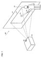
- FIG. 1 A schematic illustrative view of an image display system in accordance with an example of this embodiment of the present invention is shown in Fig. 1.
- a projector 20 which is a front-projection-type display device provided substantially facing a screen 10, projects a given image for presentation.
- a presenter 30 gives a presentation to an audience, while using a light spot 70 projected from a laser pointer 50 to point at a desired position of an image in an image display region 12, which is a display area on the screen 10.
- the image appearances on the image display region 12 will vary greatly, depending on factors such as the type of the screen 10 and ambient light 80.
- the type of the screen 10 could make it seem to be white with a yellow cast or white with a blue cast.
- differences in the ambient light 80 could make the same white that is displayed by the projector 20 appear to be a bright white or a dull white.
- this projector 20 has become smaller and easier to transport. For that reason, it has become possible for the presenter 30 to perform presentations at a client's location, by way of example, but it is difficult to adjust colors to match the environment at the client's location and the manual adjustment of colors at the client's location takes too much time.
- FIG. 2 A functional block diagram of the image processing section within a conventional projector is shown in Fig. 2.
- This conventional projector inputs an R1 signal, a G1 signal, and a B1 signal, which form RGB signals in analog format sent from a PC or the like, to an A/D conversion section 110 and then the input signals are color-converted into digital format of an R2 signal, a G2 signal, and a B2 signal by a projector image processing section 100.
- An R3 signal, a G3 signal, and a B3 signal that have been subjected to the color conversion are input to a D/A conversion section 180, and an R4 signal, a G4 signal, and a B4 signal that have been converted into analog form are input to a light valve (L/V) drive section 190, to drive a liquid-crystal light valve and thereby display an image.
- L/V light valve
- the projector image processing section 100 which is controlled by a CPU 200, comprises a projector color conversion section 120 and a profile management section 130.
- the projector color conversion section 120 converts the RGB digital signals (the R2 signal, G2 signal, and B2 signal) from the A/D conversion section 110 into RGB digital signals for projector output (the R3 signal, G3 signal, and B3 signal), based on a projector input-output profiles that are managed by the profile management section 130.
- profile in this case refers to characteristic data.
- the conventional projector can only perform color conversion based on input-output profiles that indicate input-output characteristics which are specific to that particular projector, and thus no consideration is paid to the viewing environment in which the image is projected and displayed.
- the color appearances are determined by three factors: light, the reflection or transmission of light by objects, and vision.
- This embodiment of the present invention implements an image display system that can reproduce identical colors, by detecting the viewing environment of light including the reflection or transmission of that light by objects, irrespective of the environment in which it is used.
- the image appearance is also affected by the distance between the projector 20 and the screen 10. It is possible to measure the distance between the projector 20 and the screen 10 and correct the image from consideration of that distance, but the provision of a distance measurement means in addition to the image correction means would make the image display system itself much larger.
- images are corrected without having to provide a distance measurement means, by applying an image processing method that is not dependent on the distance between the projector 20 and the screen 10.
- the device is provided with a color light sensor 60 that functions as viewing environment detection means for detecting the viewing environment, as shown in Fig. 1, where viewing environment information from the color light sensor 60 is input to the projector 20.
- the color light sensor 60 measures color light information (more specifically, RGB or XYZ tristimulus values) within the image display region 12 of the screen 10. In this case, the color light sensor 60 detects tristimulus values of an image that is displayed in the image display region 12.
- tristimulus values may be XYZ values and xbar, ybar, and zbar values that are color matching function values of those XYZ values, together with RGB values and rbar, gbar, and bbar values that are color matching function values of those RGB values, by way of example.
- the projector 20 is provided with brightness correction means, for correcting brightness information that is included in the viewing environment information to conform with the brightness of the ideal environment, based on the viewing environment information, if the image brightness in the viewing environment differs from the image brightness in the ideal environment; color difference calculation means for calculating color difference between color information included in the viewing environment information, in which the brightness information has been corrected, and color information of an image in the ideal environment; and image correction means for correcting image display information that is used for displaying the image, based on the calculated color difference.
- brightness correction means for correcting brightness information that is included in the viewing environment information to conform with the brightness of the ideal environment, based on the viewing environment information, if the image brightness in the viewing environment differs from the image brightness in the ideal environment
- color difference calculation means for calculating color difference between color information included in the viewing environment information, in which the brightness information has been corrected, and color information of an image in the ideal environment
- image correction means for correcting image display information that is used for displaying the image, based on the calculated color difference.
- color difference correction means that operates when the value of the above described color difference lies outside the given permissible correction range, to correct the color difference in such a manner that is lies within the permissible correction range.
- sequence of image processing for correcting the image is such that a white image is projected from the projector 20 to the screen 10 at each of given gray scales and the viewing environment is detected by measuring tristimulus values of the image in the image display region 12 by the color light sensor 60.
- the correction of the image display information for each of those gray scales is based on those tristimulus values.
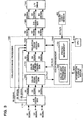
- FIG. 3 A functional block diagram of the image processing section within the projector 20 in accordance with an example of this embodiment is shown in Fig. 3.
- the projector 20 inputs the R1 signal, G1 signal, and B1 signal (which form RGB signals in analog format, sent from a PC or the like) to the A/D conversion section 110, and the projector image processing section 100 performs color conversion on the digital R2 signal, G2 signal, and B2 signal.
- the projector 20 inputs the color-converted R3 signal, G3 signal, and B3 signal to the D/A conversion section 180, then inputs the analog-converted R4 signal, G4 signal, and B4 signal to the light valve (L/V) drive section 190 which projects and displays the image by driving a liquid-crystal light valve.
- L/V light valve
- the projector image processing section 100 of the projector 20 in accordance with this embodiment comprises a color signal conversion section 160, a color signal reverse-conversion section 170, a color management section 150, and the projector color conversion section 120.
- the color signal conversion section 160 converts the digital RGB signals (R2 signal, G2 signal, and B2 signal) from the A/D conversion section 110 into XYZ values (X1, Y1, Z1). Note that the colors represented by RGB signals are device-dependent colors that are affected by the input-output device, such as the projector 20, whereas the XYZ values are device-independent colors that are the same regardless of the device.
- the color signal conversion section 160 outputs the converted XYZ values (X1, Y1, Z1) to the color management section 150.
- the color management section 150 takes the XYZ values (X1, Y1, Z1) that have been input from the color signal conversion section 160 and converts them into XYZ values (X2, Y2, Z2) that adapt to the viewing environment, based on a measured value from the color light sensor 60 that is the viewing environment detection means.
- the color management section 150 also comprises a color light information processing section 140 and the profile management section 130 that manages the above described input-output profiles for the projector 20.
- FIG. 4 A functional block diagram of the color light information processing section 140 in accordance with an example of this embodiment is shown in Fig. 4.
- the color light information processing section 140 comprises a Y1x1y1 conversion section 141, which converts color signals (X1, Y1, Z1) in XYZ format for an ideal environment from the color signal conversion section 160 into color signals (Y1, x1 y1) in Yxy format; a Y3x3y3 conversion section 143, which converts color signals (X3, Y3, Z3) in XYZ format from the color light sensor 60 that represent the viewing environment into color signals (Y3, x3, y3) in Yxy format; and a Y substitution section 142 that functions as brightness correction means.
- the Y substitution section 142 substitutes Y3 of the color signals (Y3, x3, y3) with Y1, based on Y1, which is part of the color signals from the color signal conversion section 160, and the color signals (Y3, x3, y3) from the Y3x3y3 conversion section 143.
- the color light information processing section 140 comprises color difference correction calculation section 144 that calculates color differences and a tristimulus values conversion section 147 that converts color signals into tristimulus values (X2, Y2, Z2), based on the calculated color differences.
- the color difference correction calculation section 144 comprises color difference calculation section 145, a Y2x2y2 conversion section 146, and an environment subjective coefficient correction section 148.
- the color difference calculation section 145 calculates color differences between the color signals (Y1, x3, y3) from the Y substitution section 142 and the color signals (Y1, x1, y1) from the Y1x1y1 conversion section 141.
- the human eye has mechanisms such as color adaptation, brightness adaptation, and darkness adaptation that accommodate to the main color lighting of the surroundings, such as artificial light, and affect way in which colors are seen. For that reason, it may happen that a correction that is thought to be optimal in the numerical sense become over-correction.
- this embodiment is provided with the environment subjective coefficient correction section 148, which is color difference correction means.
- the environment subjective coefficient correction section 148 determines whether or not the values of ⁇ x and ⁇ y lie within a given permissible correction range.
- the environment subjective coefficient correction section 148 outputs ⁇ x and ⁇ y unchanged to the Y2x2y2 conversion section 146 as ⁇ x' and ⁇ y'.
- the environment subjective coefficient correction section 148 corrects ⁇ x and ⁇ y so that they do lie within the permissible correction range, and output the corrected values of ⁇ x and ⁇ y as ⁇ x' and ⁇ y' to the Y2x2y2 conversion section 146.
- the value of k is greater than 0.0 but less than or equal to 1.0.
- the value of k is larger when the viewing environment is dark and smaller when the viewing environment is light. This is because difference between the actual image and the ideal image becomes larger as the viewing environment becomes brighter, and the human eyes can adapt to a certain degree in spite of their imperfectness with respect to such environment information.
- ⁇ x' is half the value of ⁇ x, so the correction is done by half the ordinary amount of correction ⁇ x, from consideration of adaptation of the image display information. If k is 0.9 when the environment is dark, ⁇ x' is nine-tenths the magnitude of ⁇ x, so the image display information is not corrected significantly.
- the coefficient k is a functional value that varies with Y1, which is brightness information of an image in an ideal environment.
- Y1 is brightness information of an image in an ideal environment.
- the human eye has mechanisms such as color adaptation and brightness adaptation, and the levels of adaptation differ between various gray levels, such as high gray scale regions, medium gray scale regions, and low gray scale regions. It is therefore possible to obtain correction amounts ( ⁇ x' and ⁇ y') that are suitable for different gray scales, by first obtaining a k value for the brightness, then determining the optimal k value for each gray scale region.
- the Y2x2y2 conversion section 146 outputs values (x2, y2), which are the those of the ideal color (x1, y1) corrected by ⁇ x' and ⁇ y' from the environment subjective coefficient correction section 148, together with Y2 to the tristimulus values conversion section 147. Note that the tristimulus values conversion section 147 uses Y1 and Y2 without modification.
- the tristimulus values conversion section 147 converts the color signals (Y2, x2, y2) from the Y2x2y2 conversion section 146 into tristimulus values (X2, Y2, Z2).
- the color light information processing section 140 outputs the tristimulus values (X2, Y2, Z2) from the tristimulus values conversion section 147 to the color signal reverse-conversion section 170.
- the profile management section 130 functions as the above described image correction means and creates the input-output profiles for the RGB signals of the projector 20. Note that each input-output profile is part of the information for image display used for displaying images.
- the profile management section 130 also manages the RGB input-output characteristic of the projector 20, using the created input-output profiles for the RGB signals.
- the color signal reverse-conversion section 170 performs a reverse conversion on the XYZ values (X2, Y2, Z2) from the color light information processing section 140 to convert them into RGB digital signals (an R5 signal, a G5 signal, and a B5 signal), using a inverse matrix of the matrix of the above-described color signal conversion section 160.
- the projector color conversion section 120 takes the RGB digital signals (the R5 signal, G5 signal, and B5 signal) from the color signal reverse-conversion section 170 and converts them into the RGB digital signals (the R3 signal, G3 signal, and B3 signal) for projector output, with reference to the projector profile managed by the profile management section 130.
- the projector image processing section 100 that is controlled by the CPU 200 comprises the projector color conversion section 120 and the profile management section 130.
- the projector color conversion section 120 takes the RGB digital signals (the R6 signal, G6 signal, and B6 signal) from the A/D conversion section 110 and converts them into the RGB digital signals for projector output (the R3 signal, G3 signal, and B3 signal), based on the input-output profiles of the RGB signals that are managed by the profile management section 130.
- the RGB digital signal for projector output that have been output from the projector color conversion section 120 are converted into the RGB analog signals (the R4 signal, G4 signal, and B4 signal) by the D/A conversion section 180, and a liquid-crystal light valve is driven by the L/V drive section 190 to project and display an image, based on those RGB analog signals.
- a presentation image that has been corrected in a manner that is appropriated for the viewing environment can be displayed, when image display information is corrected for each gray scale and the actual presentation image is displayed.
- This embodiment makes it possible to obtain color difference for color alone, excluding the brightness element, by correcting the brightness information that indicates the brightness of the image in the viewing environment to conform with the brightness in an ideal environment.
- the configuration could be implemented by an A/D converter or the like as the A/D conversion section 110; a D/A converter or the like as the D/A conversion section 180; a liquid-crystal light valve driver as the L/V drive section 406; an image processing circuit and ASIC or the like as the projector color conversion section 120, the color signal conversion section 160, the color signal reverse-conversion section 170, and the color light information processing section 140; and circuitry having a storage area such as RAM or the like as the profile management section 130.
- these portions may be implemented in a hardware fashion by circuitry, or they may be implemented in a software fashion by drivers.
- the functions of the components shown in Fig. 3 may be implemented by reading out a program from an information storage medium 300.
- the information storage medium 300 could be a CD-ROM, DVD-ROM, ROM, RAM, or HDD, by way of example, and the method of reading the program therefrom could be a direct method or an indirect method.
- the hardware described below may be employed for the color light sensor 60.
- the configuration may have a color filter that selectively passes one of the stimulus value of the tristimulus values of the image displayed on the image display region 12, a photodiode that inputs a color signal from the color filter, an A/D converter that converts an analog signal from the photodiode into a digital signal, and an OP amp that amplifies that digital signal.
- the viewing environment detection means may be imaging means such as a CCD camera or a CMOS camera, instead of the color light sensor 60.
- the description of the embodying example above related to an example of the correction of an image by the Yxy format, but it is equally possible to perform image correction by another type of representative format having brightness information and color information, such as the Lab format or Luv format. If the Lab format is used, by way of example, it is possible to correct the image by a method similar to the above described one, by reading Y as L and x and y as a and b.
- the present invention can also be applied to presentations in which images are displayed by a display means other than a projection means such as the above described projector.
- this display means could be a projector using a cathode ray tube (CRT), a plasma display panel (PDP), a field emission device (FED), an electro-luminescence (EL) device, or a direct-view type of liquid crystal display device, or a digital micromirror device (DMD), by way of example.
- CTR cathode ray tube
- PDP plasma display panel
- FED field emission device
- EL electro-luminescence
- DMD digital micromirror device
- the projector is not limited to a front-projection-type device; it may equally well be of a rear-projection type.
- the time required for image correction can be shortened by the above described method of substituting brightness information, even when the present invention is applied to the above types of image display means.
- this invention is also effective in the display of images such as those at meetings, during medical treatment, in the design and fashion fields, business activities, commercials, and education, as well as general-purpose images such as those in movies, TV, videos, and games.
- the functions of the above-described projector image processing section 100 of the projector 20 may be implemented by a single image display device (such as the projector 20 itself) or by distribution between a plurality of processing devices (such as distributed processing between the projector 20 and a PC).
Landscapes
- Engineering & Computer Science (AREA)
- Multimedia (AREA)
- Signal Processing (AREA)
- Physics & Mathematics (AREA)
- Computer Hardware Design (AREA)
- General Physics & Mathematics (AREA)
- Theoretical Computer Science (AREA)
- Controls And Circuits For Display Device (AREA)
- Image Processing (AREA)
- Closed-Circuit Television Systems (AREA)
- Color Image Communication Systems (AREA)
Abstract
Description
brightness correction means for correcting brightness information included in the viewing environment information to conform with brightness of an ideal environment, based on the viewing environment information, when brightness of the image in the viewing environment differs from brightness of the image in the ideal environment;
color difference calculation means for calculating color difference based on color information included in the viewing environment information, in which the brightness information has been corrected, and color information of the image in the ideal environment;
color difference correction means for correcting the calculated color difference when the color difference lies outside a permissible correction range, so that the color difference lies within the permissible correction range; and
image correction means for correcting the image display information, based on the color difference from the color difference correction means.
brightness correction section which corrects brightness information included in the viewing environment information to conform with brightness of an ideal environment, based on the viewing environment information, when brightness of the image in the viewing environment differs from brightness of the image in the ideal environment;
a color difference calculation section which calculates color difference based on color information included in the viewing environment information, in which the brightness information has been corrected, and color information of the image in the ideal environment;
a color difference correction section which corrects the calculated color difference when the color difference lies outside a permissible correction range, so that the color difference lies within the permissible correction range; and
an image correction section which corrects the image display information, based on the color difference from the color difference correction section. The present invention makes it possible to reproduce the image appearance to suit the human eye, without over-correction, by correcting the color difference to lie within the permissible correction range, if the obtained color difference does not lie within the permissible correction range.Note that the permissible correction range is a range in which over-correction does not occur when the image display information for displaying the image is corrected by a color difference value, by way of example.The present invention also makes it possible to obtain the color difference for color alone, excluding the brightness element, by correcting the brightness information that indicates the brightness of the image in the viewing environment to conform with the brightness in an ideal environment.This makes it possible to correct image display information rapidly, by applying correction amounts as the color difference, by way of example.It is therefore possible to implement an image display system that enables corrections of the way in which the image is seen, within a short time.Note that the brightness information may be data such as the L value of colors expressed in Lab format or the Y value of colors expressed in Yxy format (or xyY format), by way of example. Similarly, the color information may be the a and b values of colors expressed in Lab format or the x and y values of colors expressed in Yxy format.The x value, y value, and z value in this case represent ratios of X to Y to Z that add up to 1, and a color gamut can be expressed as a bell-shaped color triangle on an xy chromaticity diagram by representing them in Yxy format. The Lab format may also be used, enabling representation of the color gamut as a circle. The Yxy format and Lab format are determined as international standards by the International Commission on Illumination (CIE). The image display information corresponds to data such as an input-output profile or look-up table.
the brightness correction means;
the color difference calculation means;
the color difference correction means;
the image correction means; and
means for projecting a corrected image towards the display area. This makes it possible to detect the viewing environment appropriately by using the viewing environment detection means even when using a front-projection-type image projection device and the distance between the projection means and the screen having a display area has been altered by a change in the environment in which it is installed.
a step of generating the viewing environment information;
a color difference calculation step of calculating color difference between a given image in the viewing environment and the given image in an ideal environment, based on the generated viewing environment information;
a color difference correction step of correcting the calculated color difference when the color difference lies outside a permissible correction range so that the color difference lies within the permissible correction range; and
a step of correcting the image display information, based on the color difference output by the color difference correction step. The present invention makes it possible to reproduce the image appearance to suit the human eye, without over-correction, by correcting the color difference to lie within the permissible correction range, when the obtained color difference does not lie within the permissible correction range.The present invention also makes it possible to correct image display information rapidly, by applying color differences as amounts of correction, by way of example.It is therefore possible to correct the way in which the image is seen, within a short period of time.
the color difference correction step may comprise:
a step of correcting brightness information included in the viewing environment information to conform with brightness of the ideal environment, based on the viewing environment information, when brightness of the image in the viewing environment differs from brightness of the image in the ideal environment; and
a step of calculating the color difference based on color information included in the viewing environment information, in which the brightness information has been corrected, and color information of the image in the ideal environment. This makes it possible to obtain color difference for color alone, excluding the brightness element, by correcting the brightness information that indicates the brightness of the image in the viewing environment to conform with the brightness in an ideal environment.In this image processing method, image information for the ideal environment and the viewing environment information may be expressed in Lab format or Yxy format. The brightness correction step may comprise a step of substituting the L value or Y value of the viewing environment information into the L value or Y value of the image information for the ideal environment.This makes it possible to rapidly obtain the color difference between x3 and y3 included in the viewing environment information and the color values x1 and y1 for the ideal environment, by substituting the brightness value Y3 included in the viewing environment information into the brightness value Y1 for the ideal environment, if an image is expressed in Yxy format, by way of example.
means which generates the viewing environment information;
color difference calculation means which calculates color difference between a given image in the viewing environment and the given image in an ideal environment, based on the generated viewing environment information;
color difference correction means which corrects the calculated color difference when the color difference lies outside a permissible correction range so that the color difference lies within the permissible correction range; and
means which corrects the image display information, based on the color difference output by the color difference correction means. The present invention makes it possible to reproduce the image appearance to suit the human eye, without over-correction, by correcting the color difference to lie within the permissible correction range, when the obtained color difference does not lie within the permissible correction range.The present invention makes it possible to obtain color difference for color alone, excluding the brightness element, by correcting the brightness information that indicates the brightness of the image in the viewing environment to conform with the brightness in an ideal environment.This makes it possible to correct image display information rapidly, by applying correction amounts to the color difference, by way of example.It is therefore possible to implement an image display system that enables corrections of the way in which the image is seen, within a short time.
the color difference correction means may comprise:
means which corrects brightness information included in the viewing environment information to conform with brightness of the ideal environment, based on the viewing environment information, when brightness of the image in the viewing environment differs from brightness of the image in the ideal environment; and
means which calculates the color difference based on color information included in the viewing environment information, in which the brightness information has been corrected, and color information of the image in the ideal environment. The present invention makes it possible to obtain color difference for color alone, excluding the brightness element, by correcting the brightness information that indicates the brightness of the image in the viewing environment to conform with the brightness in an ideal environment.
Claims (12)
- An image display system of environment-compliant type which corrects image display information for displaying an image and displays the image, based on viewing environment information obtained by a viewing environment detection means which detects a viewing environment in a display area of the image, the image display system comprising:brightness correction means for correcting brightness information included in the viewing environment information to conform with brightness of an ideal environment, based on the viewing environment information, when brightness of the image in the viewing environment differs from brightness of the image in the ideal environment;color difference calculation means for calculating color difference based on color information included in the viewing environment information, in which the brightness information has been corrected, and color information of the image in the ideal environment;color difference correction means for correcting the calculated color difference when the color difference lies outside a permissible correction range, so that the color difference lies within the permissible correction range; andimage correction means for correcting the image display information, based on the color difference from the color difference correction means.
- The image display system as defined by claim 1,
wherein the color difference correction means outputs the color difference by multiplying the color difference input to the color difference correction means by a given coefficient. - The image display system as defined by claim 2,
wherein the coefficient is a functional value that varies according to the brightness information of the image in an ideal environment or the brightness information included in the viewing environment information. - The image display system as defined by claim 3, comprises a front-projection-type image projection device including:the brightness correction means;the color difference calculation means;the color difference correction means;the image correction means; andmeans for projecting a corrected image towards the display area.
- An image display system of environment-compliant type which corrects image display information for displaying an image and displays the image, based on viewing environment information obtained by a viewing environment detection means which detects a viewing environment in a display area of the image, the image display system comprising:a brightness correction section which corrects brightness information included in the viewing environment information to conform with brightness of an ideal environment, based on the viewing environment information, when brightness of the image in the viewing environment differs from brightness of the image in the ideal environment;a color difference calculation section which calculates color difference based on color information included in the viewing environment information, in which the brightness information has been corrected, and color information of the image in the ideal environment;a color difference correction section which corrects the calculated color difference when the color difference lies outside a permissible correction range, so that the color difference lies within the permissible correction range; andan image correction section which corrects the image display information, based on the color difference from the color difference correction section.
- An image processing method of environment-compliant type which corrects image display information for displaying an image, based on viewing environment information indicating a viewing environment in a display area of the image, the image processing method comprising:a step of generating the viewing environment information;a color difference calculation step of calculating color difference between a given image in the viewing environment and the given image in an ideal environment, based on the generated viewing environment information;a color difference correction step of correcting the calculated color difference when the color difference lies outside a permissible correction range so that the color difference lies within the permissible correction range; anda step of correcting the image display information, based on the color difference output by the color difference correction step.
- The image processing method as defined by claim 6,
wherein the color difference that is input in the color difference correction step is multiplied by a given coefficient and is output. - The image processing method as defined by claim 7,
wherein the viewing environment information comprises color information indicating color of the image in the viewing environment and brightness information indicating brightness of the image in the viewing environment, and
wherein the color difference correction step comprises:a step of correcting brightness information included in the viewing environment information to conform with brightness of the ideal environment, based on the viewing environment information, when brightness of the image in the viewing environment differs from brightness of the image in the ideal environment; anda step of calculating the color difference based on color information included in the viewing environment information, in which the brightness information has been corrected, and color information of the image in the ideal environment. - A computer-readable information storage medium which stores program for correcting image display information for displaying an image, based on viewing environment information indicating a viewing environment in a display area of the image, the information storage medium comprising program to implement on a computer:means for generates the viewing environment information;color difference calculation means which calculates color difference between a given image in the viewing environment and the given image in an ideal environment, based on the generated viewing environment information;color difference correction means which corrects the calculated color difference when the color difference lies outside a permissible correction range so that the color difference lies within the permissible correction range; andmeans which corrects the image display information, based on the color difference output by the color difference correction means.
- The information storage medium as defined by claim 9,
wherein the color difference correction means outputs the color difference by multiplying the color difference input to the color difference correction means by a given coefficient. - The information storage medium as defined by claim 10,
wherein the coefficient is a functional value that varies according to the brightness information of the image in an ideal environment or the brightness information included in the viewing environment information. - The information storage medium as defined by claim 11,
wherein the viewing environment information comprises color information indicating color of the image in the viewing environment and brightness information indicating brightness of the image in the viewing environment, and
wherein the color difference correction means comprises:means which corrects brightness information included in the viewing environment information to conform with brightness of the ideal environment, based on the viewing environment information, when brightness of the image in the viewing environment differs from brightness of the image in the ideal environment; andmeans which calculates the color difference based on color information included in the viewing environment information, in which the brightness information has been corrected, and color information of the image in the ideal environment.
Applications Claiming Priority (3)
| Application Number | Priority Date | Filing Date | Title |
|---|---|---|---|
| JP2000257160 | 2000-08-28 | ||
| JP2000257160A JP3707371B2 (en) | 2000-08-28 | 2000-08-28 | Image display system, image processing method, and information storage medium |
| PCT/JP2001/007377 WO2002019308A1 (en) | 2000-08-28 | 2001-08-28 | Environment-adapted image display system, image processing method, and information storage medium |
Publications (3)
| Publication Number | Publication Date |
|---|---|
| EP1315142A1 true EP1315142A1 (en) | 2003-05-28 |
| EP1315142A4 EP1315142A4 (en) | 2004-03-17 |
| EP1315142B1 EP1315142B1 (en) | 2013-03-13 |
Family
ID=18745669
Family Applications (1)
| Application Number | Title | Priority Date | Filing Date |
|---|---|---|---|
| EP01958569A Expired - Lifetime EP1315142B1 (en) | 2000-08-28 | 2001-08-28 | Environment-adapted image display system and image processing method |
Country Status (5)
| Country | Link |
|---|---|
| US (1) | US6940531B2 (en) |
| EP (1) | EP1315142B1 (en) |
| JP (1) | JP3707371B2 (en) |
| CN (1) | CN1172287C (en) |
| WO (1) | WO2002019308A1 (en) |
Families Citing this family (10)
| Publication number | Priority date | Publication date | Assignee | Title |
|---|---|---|---|---|
| JP3744778B2 (en) * | 2000-08-28 | 2006-02-15 | セイコーエプソン株式会社 | Image projection apparatus, image processing method, and information storage medium |
| JP3729252B2 (en) * | 2001-03-26 | 2005-12-21 | セイコーエプソン株式会社 | Image processing system, program, and information storage medium |
| JP3719411B2 (en) * | 2001-05-31 | 2005-11-24 | セイコーエプソン株式会社 | Image display system, projector, program, information storage medium, and image processing method |
| JP2003323610A (en) * | 2002-03-01 | 2003-11-14 | Nec Corp | Projector color correction method and color correction device |
| US7110598B2 (en) * | 2002-08-28 | 2006-09-19 | Micron Technology, Inc. | Automatic color constancy for image sensors |
| JP3690402B2 (en) * | 2003-03-28 | 2005-08-31 | セイコーエプソン株式会社 | Image processing system, projector, program, information storage medium, and image processing method |
| CN101512630B (en) * | 2006-08-29 | 2011-06-22 | 松下电器产业株式会社 | Image display method and image display device |
| US20120135783A1 (en) * | 2010-11-29 | 2012-05-31 | Google Inc. | Mobile device image feedback |
| US20230326175A1 (en) * | 2020-08-28 | 2023-10-12 | Xi'an Novastar Tech Co., Ltd. | Method for a Luminance and Chrominance Correction |
| CN119811299B (en) * | 2025-01-22 | 2025-11-25 | 合肥维信诺科技有限公司 | Gamma correction methods, devices, equipment, and media for display modules |
Family Cites Families (13)
| Publication number | Priority date | Publication date | Assignee | Title |
|---|---|---|---|---|
| JP2518848B2 (en) * | 1987-05-30 | 1996-07-31 | キヤノン株式会社 | White balance adjustment device |
| JP3298072B2 (en) * | 1992-07-10 | 2002-07-02 | ソニー株式会社 | Video camera system |
| US5956044A (en) | 1993-05-07 | 1999-09-21 | Eastman Kodak Company | Imaging device to media compatibility and color appearance matching with flare, luminance, and white point comparison |
| US6081254A (en) * | 1993-08-12 | 2000-06-27 | Hitachi, Ltd. | Color correction system of imaging apparatus |
| JP3134660B2 (en) * | 1994-04-14 | 2001-02-13 | 松下電器産業株式会社 | Color conversion method and color conversion device |
| KR100355378B1 (en) * | 1996-01-15 | 2002-12-26 | 삼성전자 주식회사 | Color image display method under various illumination light |
| GB2335326B (en) | 1997-10-31 | 2002-04-17 | Sony Corp | Image processing apparatus and method and providing medium. |
| JP3714163B2 (en) * | 1997-12-12 | 2005-11-09 | 株式会社日立製作所 | Video display system |
| JPH11355797A (en) | 1998-06-04 | 1999-12-24 | Olympus Optical Co Ltd | Liquid crystal color display device |
| KR100299759B1 (en) * | 1998-06-29 | 2001-10-27 | 구자홍 | Automatic display device and method of video display device |
| US6456339B1 (en) * | 1998-07-31 | 2002-09-24 | Massachusetts Institute Of Technology | Super-resolution display |
| JP2001060082A (en) * | 1999-08-24 | 2001-03-06 | Matsushita Electric Ind Co Ltd | Color reproduction terminal device and network color reproduction system |
| JP3497805B2 (en) * | 2000-08-29 | 2004-02-16 | オリンパス株式会社 | Image projection display device |
-
2000
- 2000-08-28 JP JP2000257160A patent/JP3707371B2/en not_active Expired - Fee Related
-
2001
- 2001-08-28 EP EP01958569A patent/EP1315142B1/en not_active Expired - Lifetime
- 2001-08-28 CN CNB018033636A patent/CN1172287C/en not_active Expired - Fee Related
- 2001-08-28 US US10/111,321 patent/US6940531B2/en not_active Expired - Lifetime
- 2001-08-28 WO PCT/JP2001/007377 patent/WO2002019308A1/en not_active Ceased
Also Published As
| Publication number | Publication date |
|---|---|
| EP1315142B1 (en) | 2013-03-13 |
| US20020180766A1 (en) | 2002-12-05 |
| CN1172287C (en) | 2004-10-20 |
| JP2002072993A (en) | 2002-03-12 |
| CN1394329A (en) | 2003-01-29 |
| EP1315142A4 (en) | 2004-03-17 |
| US6940531B2 (en) | 2005-09-06 |
| WO2002019308A1 (en) | 2002-03-07 |
| JP3707371B2 (en) | 2005-10-19 |
Similar Documents
| Publication | Publication Date | Title |
|---|---|---|
| US7345692B2 (en) | Environment-compliant image display system and image processing method | |
| US7542055B2 (en) | Image display system, projector, information storage medium, and image processing method | |
| EP1265219B1 (en) | Environment adaptive image display system, image processing method and information storing medium | |
| EP2302919B1 (en) | Projector | |
| JP5354265B2 (en) | Liquid crystal display | |
| EP1205902B1 (en) | Image display system, image processing method, and information storage medium | |
| JP3894302B2 (en) | Image display system, image processing method, program, and information storage medium | |
| US6927784B2 (en) | Image display system, projector, program, information storage medium, and image processing method | |
| US8243210B2 (en) | Apparatus and method for ambient light adaptive color correction | |
| EP1370092A1 (en) | Environment-adaptive image display system, information storage medium, and image processing method | |
| JP4110408B2 (en) | Image display system, projector, image processing method, and information storage medium | |
| US20090289951A1 (en) | Environment-compliant image display system, projector, and program | |
| EP1178672A2 (en) | Environment-compliant image display and information storage medium | |
| JP4030199B2 (en) | Projection type LCD | |
| US6940531B2 (en) | Environment-Compliant image display system, image processing method, and information storage medium | |
| US7656462B2 (en) | Systems and methods for modifying master film for viewing at different viewing locations |
Legal Events
| Date | Code | Title | Description |
|---|---|---|---|
| PUAI | Public reference made under article 153(3) epc to a published international application that has entered the european phase |
Free format text: ORIGINAL CODE: 0009012 |
|
| 17P | Request for examination filed |
Effective date: 20020620 |
|
| AK | Designated contracting states |
Designated state(s): AT BE CH CY DE DK ES FI FR GB GR IE IT LI LU MC NL PT SE TR |
|
| A4 | Supplementary search report drawn up and despatched |
Effective date: 20040202 |
|
| RIC1 | Information provided on ipc code assigned before grant |
Ipc: 7H 04N 9/73 A Ipc: 7H 04N 5/58 B |
|
| RBV | Designated contracting states (corrected) |
Designated state(s): AT BE CH DE FR GB IT LI NL |
|
| 17Q | First examination report despatched |
Effective date: 20090804 |
|
| REG | Reference to a national code |
Ref country code: DE Ref legal event code: R079 Ref document number: 60147768 Country of ref document: DE Free format text: PREVIOUS MAIN CLASS: H04N0009730000 Ipc: H04N0009770000 |
|
| GRAP | Despatch of communication of intention to grant a patent |
Free format text: ORIGINAL CODE: EPIDOSNIGR1 |
|
| RIC1 | Information provided on ipc code assigned before grant |
Ipc: H04N 9/31 20060101ALN20120904BHEP Ipc: H04N 9/77 20060101AFI20120904BHEP |
|
| RBV | Designated contracting states (corrected) |
Designated state(s): DE FR GB |
|
| GRAS | Grant fee paid |
Free format text: ORIGINAL CODE: EPIDOSNIGR3 |
|
| GRAA | (expected) grant |
Free format text: ORIGINAL CODE: 0009210 |
|
| AK | Designated contracting states |
Kind code of ref document: B1 Designated state(s): DE FR GB |
|
| REG | Reference to a national code |
Ref country code: GB Ref legal event code: FG4D |
|
| REG | Reference to a national code |
Ref country code: DE Ref legal event code: R096 Ref document number: 60147768 Country of ref document: DE Effective date: 20130508 |
|
| PLBE | No opposition filed within time limit |
Free format text: ORIGINAL CODE: 0009261 |
|
| STAA | Information on the status of an ep patent application or granted ep patent |
Free format text: STATUS: NO OPPOSITION FILED WITHIN TIME LIMIT |
|
| 26N | No opposition filed |
Effective date: 20131216 |
|
| REG | Reference to a national code |
Ref country code: DE Ref legal event code: R097 Ref document number: 60147768 Country of ref document: DE Effective date: 20131216 |
|
| REG | Reference to a national code |
Ref country code: FR Ref legal event code: PLFP Year of fee payment: 16 |
|
| REG | Reference to a national code |
Ref country code: FR Ref legal event code: PLFP Year of fee payment: 17 |
|
| PGFP | Annual fee paid to national office [announced via postgrant information from national office to epo] |
Ref country code: FR Payment date: 20170714 Year of fee payment: 17 Ref country code: GB Payment date: 20170823 Year of fee payment: 17 Ref country code: DE Payment date: 20170822 Year of fee payment: 17 |
|
| REG | Reference to a national code |
Ref country code: DE Ref legal event code: R119 Ref document number: 60147768 Country of ref document: DE |
|
| GBPC | Gb: european patent ceased through non-payment of renewal fee |
Effective date: 20180828 |
|
| PG25 | Lapsed in a contracting state [announced via postgrant information from national office to epo] |
Ref country code: DE Free format text: LAPSE BECAUSE OF NON-PAYMENT OF DUE FEES Effective date: 20190301 |
|
| PG25 | Lapsed in a contracting state [announced via postgrant information from national office to epo] |
Ref country code: FR Free format text: LAPSE BECAUSE OF NON-PAYMENT OF DUE FEES Effective date: 20180831 |
|
| PG25 | Lapsed in a contracting state [announced via postgrant information from national office to epo] |
Ref country code: GB Free format text: LAPSE BECAUSE OF NON-PAYMENT OF DUE FEES Effective date: 20180828 |