EP1314985A1 - Luftdaten-Messvorrichtung und Luftdaten-Messsystem für Fluggeräte - Google Patents
Luftdaten-Messvorrichtung und Luftdaten-Messsystem für Fluggeräte Download PDFInfo
- Publication number
- EP1314985A1 EP1314985A1 EP02025446A EP02025446A EP1314985A1 EP 1314985 A1 EP1314985 A1 EP 1314985A1 EP 02025446 A EP02025446 A EP 02025446A EP 02025446 A EP02025446 A EP 02025446A EP 1314985 A1 EP1314985 A1 EP 1314985A1
- Authority
- EP
- European Patent Office
- Prior art keywords
- probe
- pressure
- measuring
- air data
- angle
- Prior art date
- Legal status (The legal status is an assumption and is not a legal conclusion. Google has not performed a legal analysis and makes no representation as to the accuracy of the status listed.)
- Granted
Links
- 239000000523 sample Substances 0.000 claims abstract description 112
- 238000009530 blood pressure measurement Methods 0.000 claims description 14
- 238000001514 detection method Methods 0.000 claims description 3
- 230000007704 transition Effects 0.000 claims description 3
- 238000005259 measurement Methods 0.000 abstract description 12
- 238000009826 distribution Methods 0.000 abstract description 2
- 238000010408 sweeping Methods 0.000 description 7
- 230000003068 static effect Effects 0.000 description 6
- 238000010586 diagram Methods 0.000 description 2
- 238000012544 monitoring process Methods 0.000 description 2
- 241001261858 Alsodes Species 0.000 description 1
- 238000004364 calculation method Methods 0.000 description 1
- 238000011088 calibration curve Methods 0.000 description 1
- 230000015556 catabolic process Effects 0.000 description 1
- 238000006731 degradation reaction Methods 0.000 description 1
- 230000001419 dependent effect Effects 0.000 description 1
- 238000011982 device technology Methods 0.000 description 1
- 238000005516 engineering process Methods 0.000 description 1
- 238000002474 experimental method Methods 0.000 description 1
- 238000004519 manufacturing process Methods 0.000 description 1
- 238000000034 method Methods 0.000 description 1
- 230000007935 neutral effect Effects 0.000 description 1
- 238000003825 pressing Methods 0.000 description 1
- 230000035945 sensitivity Effects 0.000 description 1
- 238000012360 testing method Methods 0.000 description 1
Images


Classifications
-
- G—PHYSICS
- G01—MEASURING; TESTING
- G01P—MEASURING LINEAR OR ANGULAR SPEED, ACCELERATION, DECELERATION, OR SHOCK; INDICATING PRESENCE, ABSENCE, OR DIRECTION, OF MOVEMENT
- G01P5/00—Measuring speed of fluids, e.g. of air stream; Measuring speed of bodies relative to fluids, e.g. of ship, of aircraft
- G01P5/14—Measuring speed of fluids, e.g. of air stream; Measuring speed of bodies relative to fluids, e.g. of ship, of aircraft by measuring differences of pressure in the fluid
-
- B—PERFORMING OPERATIONS; TRANSPORTING
- B64—AIRCRAFT; AVIATION; COSMONAUTICS
- B64D—EQUIPMENT FOR FITTING IN OR TO AIRCRAFT; FLIGHT SUITS; PARACHUTES; ARRANGEMENT OR MOUNTING OF POWER PLANTS OR PROPULSION TRANSMISSIONS IN AIRCRAFT
- B64D43/00—Arrangements or adaptations of instruments
- B64D43/02—Arrangements or adaptations of instruments for indicating aircraft speed or stalling conditions
-
- G—PHYSICS
- G01—MEASURING; TESTING
- G01P—MEASURING LINEAR OR ANGULAR SPEED, ACCELERATION, DECELERATION, OR SHOCK; INDICATING PRESENCE, ABSENCE, OR DIRECTION, OF MOVEMENT
- G01P13/00—Indicating or recording presence, absence, or direction, of movement
- G01P13/02—Indicating direction only, e.g. by weather vane
- G01P13/025—Indicating direction only, e.g. by weather vane indicating air data, i.e. flight variables of an aircraft, e.g. angle of attack, side slip, shear, yaw
Definitions
- the invention relates to an air data measuring device and an air data system for Aircraft, in particular for measuring flight conditions at large aircraft angles of attack.
- the measuring device according to the invention or the measuring system according to the invention can be applied to all types of aircraft, especially aircraft and missiles.
- Air data probes based only on pressure measurements which are also suitable for large Angle of attack up to 90 ° are provided.
- these require extensive and complex calibration effort.
- a suitable probe and a corresponding one Provide air data system with the lowest possible device technology and functional effort also an accurate measurement of large angles of attack and sliding angles as well as flight speeds and flight altitudes allows.
- an air data measuring device for aircraft for measuring flight conditions is provided with a probe carrier which is arranged on a structural part, at least at the transition point, and is rotationally symmetrical, which is rotatably supported by a bearing about its longitudinal axis on the structural part and is mass-balanced about its longitudinal axis , wherein the angle of rotation ( ⁇ S ) of the probe can be measured via a measuring sensor, at least two strakes being arranged symmetrically on the probe plane of symmetry on the probe, so that the probe sliding angle ⁇ S is minimized in each inflow state, and wherein for the detection of Differential pressures and an absolute pressure on the probe surface at least three pressure measuring bores are provided with these associated differential pressure transducers, the first of the pressure measuring bores being in the center or at a radial distance from the center which is smaller than the radial distance to the Center the second print has k-measuring bore and the radial distance to the center of the third bore is equal to or greater than the radi
- a symmetrical probe in the form of a radome tip which can be rotated about the longitudinal axis of the aircraft radome and which has at least one pair of straps arranged on its circumference, is used as the air data probe.
- the aerodynamic influence of the pair of strakes on the aircraft causes the rotatable probe to turn. This creates an angle of twist ⁇ S in the sliding flight around the radome axis relative to the plane of symmetry of the aircraft.
- the probe With the angle of rotation ⁇ S , the probe is in a position in which a sliding-free measurement of its angle of attack ⁇ S can be carried out via corresponding pressure bores on its surface.
- At least three pressure measuring bores are provided on the surface of a rotatable probe, which preferably forms the tip of a radome, by means of which a differential pressure ratio for each probe angle of attack ⁇ S is provided can be determined that is independent of the altitude and the airspeed.
- the altitude and speed are recorded using an absolute pressure and differential pressure sensor. To determine the current absolute static pressure of the undisturbed flow with which the flight altitude is determined, the influence of the flight speed with the respective differential pressure is eliminated.
- the system described is an air data system, which is preferably in addition to a conventional system especially for the measurement of large angles of attack is provided.
- Air data system when combined with a conventional one Air data system operated, security requirements due to availability redundant measurements can be better met.
- the system can too can be used as the sole pressure measuring system in the relevant angle of incidence range.
- the probe 1 has a probe carrier 1a which is attached to a suitable, i.e. aerodynamically undisturbed point of the aircraft structure or one Structural part 3 is provided.
- the structural part 3 is at least at the transition point to the probe carrier 1a rotationally symmetrical.
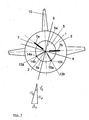
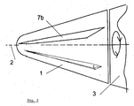
- Structural part 3 the front fuselage segment of an aircraft ( Figures 1 and 2), see above that the probe carrier 1a or its probe surface 5 in this case Forms part of the radome tip of the aircraft.
- the probe 1 is balanced in terms of mass and rotatable about its longitudinal axis 2 on the structural part 3 by means of a bearing arranged largely smoothly. The mass balance does not make them flowed probe 1 is in balance in every rotational position.
- a reference plane 4 is given in FIG. 1, through which an upper probe half 5a and a lower probe half 5b are defined.
- An even number of strakes 7 and in particular two strakes 7a and 7b are preferably arranged on the probe carrier 1a.
- any number of strakes and in particular only one strake can also be provided, wherein if only one strake is used, this is arranged on the plane of symmetry 9.
- the strakes 7 and 7a, 7b are attached symmetrically to the plane of symmetry 9 of the probe carrier 1a running perpendicular to the reference plane 4.
- the probe 1 assumes an equilibrium position depending on the direction of the inflow, with the inflow angle ⁇ S lying in the plane of symmetry 9.
- the probe inflow angle ⁇ S , the angle of attack ⁇ F , the sliding angle ⁇ F and the direction of the associated probe rotation angle ⁇ S are entered to explain an assumed flow state.
- the first flow rib 13a has a first 14a and a second 14b flank, and the second flow rib 13b also a first 15a and a second 15b flank.
- Ribs can also perform other functions, e.g. the generation of local flow conditions at the probe 1, with which the desired pressure conditions at the pressure measuring holes explained below.
- the strips make a larger one compared to a smooth probe surface Pressure difference reached, whereby the measurement signals assume larger values. This results in better resolution and increased accuracy of the measured values.
- an angle of rotation ⁇ S of the probe 1 is established relative to the plane of symmetry 10 of the aircraft.
- the angle of rotation ⁇ S is measured by means of a measuring sensor according to the prior art, for example by means of an incremental angle sensor.
- the strakes 7, 7a, 7b are arranged on the upper probe half 5a. Since the probe 1 is aerodynamically stable when the strakes 7 and 7a, 7b are located on the lee side of the probe 1, the probe 1 according to the invention is provided for measuring positive angles of attack.
- Differential pressure transducers provided, of which three are essential Pressure measuring bores two each with respect to the probe plane of symmetry 9 non-symmetrical and at least one pressure measuring hole spaced from the probe symmetry plane 9 may lie.
- three pressure measuring holes on the plane of symmetry 9 and the third pressure measuring bore can be arranged at a distance therefrom.
- two Pressure measuring holes spaced and asymmetrical with respect to the plane of symmetry 9 lie and a third pressure measuring hole on the plane of symmetry 9th be arranged.
- a fourth measuring hole can also be used to check the position of the probe on the Probe 1 may be arranged, this fourth measuring bore symmetrical to a spaced from the symmetry plane 9 of the probe 1 arranged measuring bore is provided.
- FIG. 3 shows a constellation of four measuring bores 21, 22, 23, 24, which are embedded in probe 1.
- a first measuring bore 21 preferably a second measuring bore 22, eccentrically to the tip of the probe 1 below it on the symmetry level 9 as well as a third 23 and a fourth 24 measuring bore each spaced from the plane of symmetry 9.
- the first measuring bore 21 can also be on the Tip or be arranged in the center of the probe 1.
- the third 23 and fourth 24 The measuring bore is arranged symmetrically to the plane of symmetry 9 of the probe 1, to control or monitor the symmetrical flow of the probe 1. If this control is not required, i.e. the measurement according to the invention the air data is sufficient without control, can go to the third 23 or the fourth 24 measuring bore can be dispensed with.
- differential pressure transducer 26 becomes the differential pressure (P1 - P2), below and in the figure 3 labeled P12, determined.
- a differential pressure converter 27 is over Pressure lines 27a, 27b connected between the measuring bores 21 and 23, to measure a pressure difference (P1 - P3) or P13.
- Even between the Measuring bores 33 and 34 is a differential pressure converter via pressure lines 28a, 28b 28 connected to a pressure difference (P3 - P4) or P34 too measure up.
- pressure measuring holes of the embodiment according to the Figure 3 can optionally or alternatively also other differential pressure measurements be provided, e.g. between the measuring bores 22 and 24 or between the measuring bores 21 and 23.
- the differential pressure transducers 26, 27 28 can increase the measuring accuracy the angle of attack and thus the sliding angle with a relatively large Sensitivity can be provided. This results in a relative limited pressure measuring range, which increases the functional range of the air data probe 1 is restricted to low flight speeds. This corresponds to the partial Use of the aircraft with large angles of attack, as these are only possible with limited angles Speeds can be flown.
- those with the differential pressure transducers 26, 27 connected bores 21, 22 and 21, 23 electrically or pneumatically Short-circuited via respective lines 26c, 27c with one pressure valve 26d, 27d become.
- the pressure difference between symmetrical to the plane of symmetry 9 arranged measuring holes in the embodiment of Figure 3, the holes 23, 24, always zero, since the rotatable probe 1 can be moved by means of the strakes 7a, 7b in the direction of the wind direction.
- Pressure measuring bores are therefore not for the minimal configuration Determination of the air data required, but can be provided for monitoring his. If still in flight between two symmetrically arranged measuring holes a differential pressure occurs, this can be an indicator of an error in the Serve measuring system. This can relate to a system-immanent or one external errors, e.g. due to icing or blockage of a measuring hole, Respectively.
- the measuring bores can therefore 23 and 24 or the measurement of the pressure difference (P3 - P4) or P34 for Error detection or to check the probe position.
- the absolute pressure converter 29b can also be connected to another of the measuring bores 22, 23, 24.
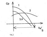
- FIG. 1 An example of the course of the coefficients CP1 ( ⁇ S ), CP2 ( ⁇ S ), CP3 ( ⁇ S ), CP4 ( ⁇ S ) as a function of the probe angle of attack ⁇ S is shown in FIG.
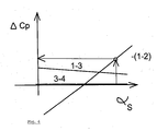
- An example of the course of the coefficients ⁇ Cp1.2 ( ⁇ S ), ⁇ Cp1.3 ( ⁇ S ), ⁇ Cp3.4 ( ⁇ S ) as a function of the probe angle of attack ⁇ S can be seen in FIG.
- the calibration functions are largely determined experimentally when setting the system before the flight, for example in a wind tunnel or in a flight test.
- the pressure measuring holes provided according to the invention and the respectively connected pressure transducers are used to set up the calibration functions of the pressure coefficient Cp, the differential pressure coefficients ⁇ Cp and a differential pressure ratio R as a function of the angle of attack of the probe 1 in the flow.
- the dynamic pressure is determined.
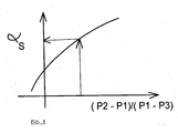
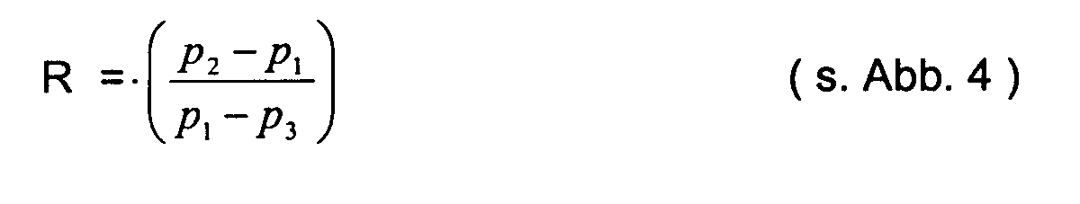
- the probe angle of attack ⁇ S (FIG. 4) and the corresponding pressure coefficient (FIG. 5) are determined on the basis of a measured differential pressure ratio.
- the determination of the static pressure P ⁇ ie the static pressure of the surroundings, is carried out using the measured absolute pressure P1, the dynamic pressure Q ⁇ determined at a current ⁇ S and the pressure coefficient, for example CP1 ( ⁇ S ), for example in accordance with the figure 5 shown calibration function.
- the probe 1 with its strakes 7a, 7b always adjusts to the direction of flight without sliding, as a result of which the rotatable probe 1 assumes a finite angle of rotation ⁇ S relative to the plane of symmetry 10 of the aircraft.
- the probe sliding angle ⁇ S is minimized, ie its value is negligible, since the probe 1 is always aligned symmetrically in the wind direction plane.
- a specific pressure distribution on the surface of the probe 1, which can be measured via the differential pressures and the absolute pressure, is created and is used to determine the angle of attack of the probe ⁇ S.
- the differential pressure ratio R enables a determination of ⁇ S independently of the height and the dynamic pressure.
- ⁇ F arctan (tan ⁇ S , cos ⁇ S )
- ⁇ F arcsin (sin ⁇ S , sin ⁇ S )
- Mach number in particular can be determined according to the status functions known in the art into the functions described above be included.
- FIG. 8 shows a further embodiment of the probe 1 according to the invention shown, wherein two pairs of holes arranged on a flow rib 13a and 13b be used, e.g. the holes 31 and 32 or alternatively the Bores 33 or 34. In both cases, the one located in the central area Hole 35 required.
- the arrangement of the pressure measuring bores 31, 32, 33, 34 next to the flanks 14a, 14b, 15a, 15b is advantageous in terms of production technology. Pressure measuring bores arranged in this way detect the generated by the flow fins 13a, 13b Flight state dependent disturbances of the flow.
- the differential pressure sensor 25 can optionally be arranged in the position.
- the differential pressure sensor 27 is via pressure lines on the one hand with the pressure measuring bore 35 in the central area of the probe and on the other hand with the pressure measuring bore 32 of the first rib 13a connected.
- a bypass valve 27d in the corresponding Pipes can be used for safety purposes in the differential pressure transducers occurring pressures can be provided.
- the differential pressure sensor 26 via pressure lines on the one hand with the pressure measuring bore 33 and the other with the pressure measuring bore 34, which are each are located on the second rib 13b.
- a bypass valve 26d in the corresponding Pipes can be used for safety purposes in the differential pressure transducers occurring pressures can be provided.
- the absolute pressure sensor 29b By means of the absolute pressure sensor 29b, the pressure lines with the measuring holes 32 on the first rib 13a and the measuring bore 33 connected to the second rib 13b is. The calculation of air data from those recorded by means of the pressure sensor Pressing takes place according to the inventive method described above.
- differential pressures determined according to the invention can also be used instead of the differential pressure transducers by means of appropriately interconnected absolute pressure transducers take place, then using appropriate functions from the determined Absolute pressures to determine the differential pressures required according to the invention are.
- measuring systems of this type can also be provided.
- a multiplication of measuring systems can cause a failure or a degradation of a Measuring systems are recognized and compensated for according to the prior art.
Landscapes
- Engineering & Computer Science (AREA)
- Aviation & Aerospace Engineering (AREA)
- Physics & Mathematics (AREA)
- General Physics & Mathematics (AREA)
- Measuring Fluid Pressure (AREA)
- Arrangements For Transmission Of Measured Signals (AREA)
Abstract
Description

- die Anordnung der Sonde ist im Rumpfspitzenbereich oder gegebenenfalls auch an einem in die Strömung hineinragenden Strukturteil angeordnet, so daß eine ungestörte Anströmung der Sonde sowie deren Radarverträglichkeit gegeben ist, wobei die Radom-Achse bzw. die Achse des Strukturteils als Windfahnenachse verwendet werden kann, wenn die Sonde zumindest in ihrem vorderen Bereich einen rotations-symmetrischen Körper bildet;
- der Aufwand zur Erstellung und Implementierung der Kalibrierfunktionen ist wegen der aerodynamischen Ausrichtung der Sonde in der Strömung verhältnismäßig gering, da ein schiebefreies Messen des Sondenanstellwinkels vorliegt und die aerodynamische Kalibrierung des Schiebewinkeleinflusses entfällt;
- die Kalibrierung des Sonden-Anstellwinkels erfolgt durch ein Höhen- und Geschwindigkeits-unabhängiges Differenzdruckverhältnis, das auf der Basis der Messung von zumindest zwei Differenzdrücken mit zumindest drei Druck-Meßbohrungen ermittelt wird;
- eine Steigerung der Meßgenauigkeit des Anstellwinkels ist durch die Verwendung von entsprechenden Differenzdruck-Aufnehmern mit reduziertem Druckbereich für den relevanten Flugbereich und entsprechenden Bypass-Leitungen auf einfache Weise ohne Änderung des Systemkonzepts möglich;
- die Bestimmung der Flughöhe erfolgt durch Messung des Absolutdrucks an einer Messbohrung sowie eines Differenzdrucks zwischen zwei Druck-Messbohrungen an der Sonden-Oberfläche, wodurch Geschwindigkeits-Unabhängigkeit des Meßparameters, also des statischen Drucks der ungestörten Anströmung, erreicht wird.
- Figur 1 eine schematische Darstellung einer Ausführungsform der erfindungsgemäßen Luftdatensonde von vorne gesehen, bei der die Anordnung der Druck-Meßbohrungen nicht dargestellt ist,
- Figur 2 eine schematische Darstellung der Ausführungsform der Figur 1 in der Seitenansicht mit einem Teil des vorderen Rumpfsegments eines Flugzeugs von der Seite gesehen,
- Figur 3 eine funktionelle Darstellung einer ersten Ausführungsform des erfindungsgemäßen Luftdatensystems, wobei eine beispielhafte Anordnung von Druck-Meßbohrungen mit einem Schaltplan für die Druck-Messung dargestellt ist,
- Figur 4 eine beispielhafte Darstellung des Verlaufs einer Kalibrier-Funktion zur Bestimmung des Sonden-Anstellwinkels αS in Abhängigkeit des gemessenen Differenzdruck-Verhältnisses mit den Druck-Meßbohrungen wie in der Konfiguration nach der Figur 3 angegeben,
- Figur 5 eine beispielhafte Darstellung des Verlaufs von Kalibrier-Funktionen zur Bestimmung der Druck-Beiwerte in Abhängigkeit des Sonden-Anstellwinkels α S für Drücke, die mit den Druck-Meßbohrungen in der Konfiguration nach der Figur 3 gemessen werden,
- Figur 6 eine beispielhafte Darstellung des Verlaufs einer Kalibrier-Funktion zur Bestimmung der Differenzdruck-Beiwerte in Abhängigkeit des Sonden-Anstellwinkels αS für Differenzdrücke, die mit den Druck-Meßbohrungen in der Konfiguration nach der Figur 3 gemessen werden,
- Figur 7 eine funktionale Darstellung der als Meßgrößen verwendeten Sondenwinkel α S und ϕ S als Funktion des Anstell- und Schiebewinkels αF bzw. βF des Flugzeugs,
- Figur 8 eine funktionelle Darstellung einer zweiten Ausführungsform des erfindungsgemäßen Luftdatensystems, wobei eine beispielhafte Anordnung von Druck-Meßbohrungen mit einem Schaltplan für die Druck-Messung dargestellt ist.
- zur Ermittlung des Sonden-Anstellwinkels α S in Abhängigkeit gemessener Differenzdruck-Verhältnisse (beispielhaft in Figur 4),
- zur Ermittlung entsprechender Beiwerte von an jeweils einer Druck-Meßbohrung anliegenden Drücken (beispielhaft in Figur 5) zur Ermittlung von Beiwerten an jeweils zwei entsprechenden Druck-Meßbohrungen anliegenden Differenzdrücken (beispielhaft in Figur 6) jeweils in Abhängigkeit vom Sonden-Anstellwinkel αS .
- die Bestimmung des Staudruckes bzw. der Flug-Geschwindigkeit aufgrund eines gemessenen Differenzdruck-Verhältnisses, wodurch α S (Figur 4) und daraus der entsprechende Differenzdruck-Beiwert (Figur 6) ermittelt wird; über eine Formel und den entsprechenden Differenzdruck wird daraus der Staudruck bestimmt;
- die Bestimmung der Flughöhe aufgrund eines gemessenen Differenzdruck-Verhältnisses, wodurch αS (Figur 4) und daraus der entsprechende Druck-Beiwert (Figur 5) ermittelt wird; über eine Formel wird aus diesem Druck-Beiwert, dem jeweiligen Staudruck und dem entsprechenden an einer Druck-Meßbohrung anliegenden absoluten Druck der herrschende statische Druck der Flughöhe bestimmt;
- die Bestimmung des Flugzeug-Anstellwinkels αF und des Flugzeug-Schiebewinkels βF aufgrund eines gemessenen Differenzdruck-Verhältnisses, wodurch α S (Figur 4) bestimmt wird, und aufgrund des Sonden-Drehwinkels ϕS ; über trigonometrische Zusammenhänge, die graphisch beispielhaft in der Figur 7 dargestellt sind, wird aus α S und ϕ S der Flugzeug-Anstellwinkel αF und der Flugzeug-Schiebewinkel βF ermittelt;
- weitere aus den vorgenannten Luftdaten ableitbare Größen.

Claims (4)
- Luftdaten-Messvorrichtung für Fluggeräte zur Messung von Flugzuständen mit einem an einem Strukturteil (3) angeordneten, zumindest an der Übergangsstelle rotations-symmetrischen Sonden-Träger (1a), der durch ein Lager um seine Längsachse (2) drehbar an dem Strukturteil (3) gelagert und massenmäßig um dessen Längsachse (2) ausgeglichen ist, wobei der Drehwinkel ( ϕ S ) der Sonde (1) über einen Mess-Aufnehmer messbar ist,
dadurch gekennzeichnet,dass auf der Sonde (1) zumindest zwei Strakes (7a, 7b) symmetrisch zur Sonden-Symmetrieebene (9) angeordnet sind, so dass der Sondenschiebewinkel β S bei jedem Anströmzustand minimiert wird,dass zur Erfassung von Differenzdrücken und eines Absolutdrucks an der Sonden-Oberfläche (5) zumindest drei Druck-Messbohrungen (21, 22, 23, 24; 31, 32, 33, 34, 35) mit diesen zugeordneten Differenzdruck-Aufnehmern (26, 27, 28, 29b) vorgesehen sind, wobei von den Druck-Messbohrungen die erste im Zentrum (2) oder in einem radialen Abstand zum Zentrum (2) liegt, der kleiner ist als der radiale Abstand zum Zentrum, den die zweite Druck-Messbohrung hat und der radiale Abstand zum Zentrum der dritten Bohrung gleich oder größer ist als der radiale Abstand der zweiten Druck-Messbohrung zum Zentrum (2), während eine der Druck-Messbohrungen in der Sonden-Symmetrieebene (9) liegt und die beiden anderen Druck-Messbohrungen in Bezug auf die Symmetrieebene (9) zueinander unsymmetrisch sind, um mittels Kalibrierfunktionen die Luftdaten der ungestörten Strömung zu bestimmen und die Ausrichtung der Sonde zu überprüfen. - Luftdaten-Messvorrichtung für Fluggeräte zur Messung von Flugzuständen nach dem Anspruch 1, dadurch gekennzeichnet, dass zwei Druck-Messbohrungen (21, 22) auf der Sonden-Symmetrieebene (9) angeordnet sind und die dritte Druck-Messbohrung (23; 24) beabstandet dazu angeordnet ist.
- Luftdaten-Messvorrichtung für Fluggeräte zur Messung von Flugzuständen nach dem Anspruch 1, dadurch gekennzeichnet, dass zumindest eine vierte Druckmess-Bohrung bezüglich einer der drei weiteren Druckmess-Bohrungen symmetrisch zur Symmetrie-Ebene liegt und daß die Druckdifferenz zwischen den symmetrischen Druck-Messbohrungen zur Fehlererkennung verwendet wird.
- Luftdaten-Messvorrichtung für Fluggeräte zur Messung von Flugzuständen nach einem der voranstehenden Ansprüche, dadurch gekennzeichnet, dass die Differenzdrucksensoren durch Bypass-Leitungen und Druckventile, wenn nötig vor zu großen Druckdifferenzen bei großen Geschwindigkeiten vor Beschädigung geschützt werden.
Applications Claiming Priority (2)
| Application Number | Priority Date | Filing Date | Title |
|---|---|---|---|
| DE10157074A DE10157074C2 (de) | 2001-11-21 | 2001-11-21 | Luftdaten-Meßvorrichtung für Fluggeräte |
| DE10157074 | 2001-11-21 |
Publications (2)
| Publication Number | Publication Date |
|---|---|
| EP1314985A1 true EP1314985A1 (de) | 2003-05-28 |
| EP1314985B1 EP1314985B1 (de) | 2010-09-01 |
Family
ID=7706422
Family Applications (1)
| Application Number | Title | Priority Date | Filing Date |
|---|---|---|---|
| EP02025446A Expired - Lifetime EP1314985B1 (de) | 2001-11-21 | 2002-11-15 | Luftdaten-Messvorrichtung und Luftdaten-Messsystem für Fluggeräte |
Country Status (5)
| Country | Link |
|---|---|
| US (1) | US6644112B2 (de) |
| EP (1) | EP1314985B1 (de) |
| AT (1) | ATE479902T1 (de) |
| CA (1) | CA2412271C (de) |
| DE (2) | DE10157074C2 (de) |
Cited By (5)
| Publication number | Priority date | Publication date | Assignee | Title |
|---|---|---|---|---|
| FR2905461A1 (fr) * | 2006-08-31 | 2008-03-07 | Peuvedic Jean Marc Le | Dispositif de mesure des differences de pression dans des fluides. |
| EP3553533A1 (de) * | 2018-04-12 | 2019-10-16 | Technische Universität Berlin | Grenzschichtsonde, messanordnung sowie verfahren zum bestimmen eines fluidstroms |
| WO2020181371A1 (en) * | 2019-03-12 | 2020-09-17 | Motus Design Group Ltd. | Airspeed sensor, system and airspeed monitoring process digitally implemented thereby or in relation thereto |
| CN112697380A (zh) * | 2020-12-10 | 2021-04-23 | 中国航空工业集团公司沈阳飞机设计研究所 | 一种标准空速管位置误差的标校结构 |
| CN112729752A (zh) * | 2021-01-26 | 2021-04-30 | 中国空气动力研究与发展中心超高速空气动力研究所 | 一种基于k形管压差测量的航天摩阻传感器 |
Families Citing this family (13)
| Publication number | Priority date | Publication date | Assignee | Title |
|---|---|---|---|---|
| US7073386B2 (en) * | 2004-06-14 | 2006-07-11 | General Electric Company | Multi-bore pressure sensing probe |
| US7284420B2 (en) * | 2004-07-13 | 2007-10-23 | Honeywell International Inc. | Air data system and method for rotary aircraft |
| US8786117B2 (en) * | 2008-06-13 | 2014-07-22 | General Electric Company | Wind turbine sensor assembly and method of assembling the same |
| US8171770B2 (en) * | 2008-09-17 | 2012-05-08 | The Boeing Company | Calibration tool for air data measurement devices |
| FR2988851B1 (fr) | 2012-03-28 | 2014-04-25 | Dassault Aviat | Procede de determination d'un etat de credibilite de mesures d'un capteur d'incidence d'un aeronef et systeme correspondant |
| FR3008073B1 (fr) * | 2013-07-04 | 2015-08-07 | Thales Sa | Aeronef comprenant une sonde de mesure et procede de determination de parametres de vol d un tel aeronef |
| FR3021116B1 (fr) * | 2014-05-13 | 2018-12-07 | Airbus Operations | Systeme de mesure destine a mesurer la vitesse d'un aeronef |
| US10921343B2 (en) | 2019-03-07 | 2021-02-16 | Bnsf Railway Company | Systems and methods for converting wind pressure to wind velocity |
| US11061048B2 (en) * | 2019-03-07 | 2021-07-13 | Bnsf Railway Company | Systems and methods for communicating information associated with wind pressures |
| CN115790737B (zh) * | 2022-11-22 | 2025-06-24 | 京仪股份有限公司 | 一种多点式风量测量装置 |
| CN116164876B (zh) * | 2023-04-26 | 2023-08-22 | 南京天晴航空航天科技有限公司 | 一种适用于尖前缘外形飞行器的嵌入式大气测量装置 |
| CN119574910B (zh) * | 2024-12-18 | 2025-09-23 | 珠海市吉大华普仪器有限公司 | 一种风速测量装置 |
| CN119738587B (zh) * | 2024-12-24 | 2026-02-10 | 太原航空仪表有限公司 | 一种固态气动角度探头 |
Citations (2)
| Publication number | Priority date | Publication date | Assignee | Title |
|---|---|---|---|---|
| US3079758A (en) * | 1960-02-23 | 1963-03-05 | Northrop Corp | Flow direction sensor |
| US5207397A (en) * | 1990-06-08 | 1993-05-04 | Eidetics International, Inc. | Rotatable nose and nose boom strakes and methods for aircraft stability and control |
Family Cites Families (4)
| Publication number | Priority date | Publication date | Assignee | Title |
|---|---|---|---|---|
| US4184149A (en) * | 1978-05-30 | 1980-01-15 | The United States Of America As Represented By The United States National Aeronautics And Space Administration | Air speed and attitude probe |
| DE3634005A1 (de) * | 1986-10-06 | 1988-04-14 | Roland Sommer | Verfahren und vorrichtung zur messung der stroemungsgeschwindigkeit einer freien stroemung im raum |
| US5369993A (en) * | 1993-06-30 | 1994-12-06 | The B. F. Goodrich Company | Three axis air data system for air vehicles |
| GB9320678D0 (en) * | 1993-10-07 | 1993-12-08 | Westland Helicopters | Static vent units |
-
2001
- 2001-11-21 DE DE10157074A patent/DE10157074C2/de not_active Expired - Fee Related
-
2002
- 2002-11-15 AT AT02025446T patent/ATE479902T1/de not_active IP Right Cessation
- 2002-11-15 EP EP02025446A patent/EP1314985B1/de not_active Expired - Lifetime
- 2002-11-15 DE DE50214623T patent/DE50214623D1/de not_active Expired - Lifetime
- 2002-11-20 CA CA002412271A patent/CA2412271C/en not_active Expired - Fee Related
- 2002-11-21 US US10/300,919 patent/US6644112B2/en not_active Expired - Lifetime
Patent Citations (2)
| Publication number | Priority date | Publication date | Assignee | Title |
|---|---|---|---|---|
| US3079758A (en) * | 1960-02-23 | 1963-03-05 | Northrop Corp | Flow direction sensor |
| US5207397A (en) * | 1990-06-08 | 1993-05-04 | Eidetics International, Inc. | Rotatable nose and nose boom strakes and methods for aircraft stability and control |
Cited By (9)
| Publication number | Priority date | Publication date | Assignee | Title |
|---|---|---|---|---|
| FR2905461A1 (fr) * | 2006-08-31 | 2008-03-07 | Peuvedic Jean Marc Le | Dispositif de mesure des differences de pression dans des fluides. |
| WO2008025931A3 (fr) * | 2006-08-31 | 2008-04-24 | Dassault Aviat | Methode et dispositif anemo-baro-clinometrique, application au positionnement d'un aeronef |
| EP3553533A1 (de) * | 2018-04-12 | 2019-10-16 | Technische Universität Berlin | Grenzschichtsonde, messanordnung sowie verfahren zum bestimmen eines fluidstroms |
| WO2019197614A1 (de) * | 2018-04-12 | 2019-10-17 | Technische Universität Berlin | Grenzschichtsonde, messanordnung sowie verfahren zum bestimmen eines fluidstroms |
| US12061211B2 (en) | 2018-04-12 | 2024-08-13 | Technische Universität Berlin | Boundary layer probe, measuring assembly, and method for determining a fluid flow |
| WO2020181371A1 (en) * | 2019-03-12 | 2020-09-17 | Motus Design Group Ltd. | Airspeed sensor, system and airspeed monitoring process digitally implemented thereby or in relation thereto |
| CN112697380A (zh) * | 2020-12-10 | 2021-04-23 | 中国航空工业集团公司沈阳飞机设计研究所 | 一种标准空速管位置误差的标校结构 |
| CN112697380B (zh) * | 2020-12-10 | 2023-04-07 | 中国航空工业集团公司沈阳飞机设计研究所 | 一种标准空速管位置误差的标校结构 |
| CN112729752A (zh) * | 2021-01-26 | 2021-04-30 | 中国空气动力研究与发展中心超高速空气动力研究所 | 一种基于k形管压差测量的航天摩阻传感器 |
Also Published As
| Publication number | Publication date |
|---|---|
| EP1314985B1 (de) | 2010-09-01 |
| ATE479902T1 (de) | 2010-09-15 |
| DE10157074C2 (de) | 2003-11-13 |
| US20030126923A1 (en) | 2003-07-10 |
| CA2412271C (en) | 2010-01-19 |
| DE10157074A1 (de) | 2003-06-05 |
| DE50214623D1 (de) | 2010-10-14 |
| US6644112B2 (en) | 2003-11-11 |
| CA2412271A1 (en) | 2003-05-21 |
Similar Documents
| Publication | Publication Date | Title |
|---|---|---|
| EP1314985B1 (de) | Luftdaten-Messvorrichtung und Luftdaten-Messsystem für Fluggeräte | |
| DE60018728T2 (de) | Feste multifunktionssonde für luftfahrzeug | |
| DE69222172T2 (de) | Anstellwinkelsensor basierend auf dem umgekehrten verhältnis von druckunterschieden | |
| DE60225502T2 (de) | Multifunktions-Luftdatenmessfühler mit neuronalem Netzwerk zur Schiebewinkelkompensation | |
| DE3124082C2 (de) | ||
| EP0851233B1 (de) | Anordnung zur dreiachsigen Messung von Beschleunigungen | |
| DE10001813C2 (de) | Meßsystem zur Ermittlung von Luftdaten eines Luftfahrzeuges sowie ein Verfahren zur Bestimmung der Luftdaten | |
| DE2254013A1 (de) | Anordnung zur pruefung eines in einem luftfahrzeug installierten traegheitsgeraets | |
| DE2046192B2 (de) | Vorrichtung zur Messung der Strömungsgeschwindigkeit | |
| EP2665930B1 (de) | Verfahren zum bestimmen der neigung eines turmes | |
| DE3407051C2 (de) | Gewichtsmeßeinrichtung für Hubschrauber | |
| DE69931790T2 (de) | Luftdrucksensor | |
| DE10112352A1 (de) | Anordnung zur Winkelmessung | |
| DE3823449A1 (de) | Messeinrichtung zur erfassung des drucks und der temperatur | |
| DE3139707A1 (de) | Nicklagerechner | |
| EP0236569B1 (de) | Verfahren und Vorrichtung zur Ermittlung eines Anströmwinkels und/oder der Windgeschwindigkeit an einer ortsfesten oder bewegten Messstelle | |
| EP2041523B1 (de) | Messanordnung zur strömungsmessung in einem kanal | |
| DE2326046C2 (de) | Verfahren und Vorrichtung zur Qualitätsprüfung von Reifen, insbesondere von Kraftfahrzeugreifen | |
| DE69717170T2 (de) | Pitot-statische sonde | |
| WO2018177736A1 (de) | Messanordnung und verfahren zum erzeugen eines ausgangsmesssignals mit zumindest einem beschleunigungssensor | |
| DE102006010219A1 (de) | Verfahren und Vorrichtung zur Erweiterung des Nutzbereichs der Luftdatenparameterberechnung in bündig eingebauten Luftdatensystemen | |
| EP0457200A2 (de) | Verfahren zur Messung von Winkeln und Winkelkennlinien mit Hilfe eines Kreisels | |
| DE19906955C1 (de) | Verfahren zur Bestimmung des Windvektors | |
| DE19752439A1 (de) | Mikromechanischer Neigungssensor, insbesondere für Kraftfahrzeuge | |
| EP0249848B1 (de) | System zur Bestimmung der Fluggeschwindigkeit von Hubschraubern |
Legal Events
| Date | Code | Title | Description |
|---|---|---|---|
| PUAI | Public reference made under article 153(3) epc to a published international application that has entered the european phase |
Free format text: ORIGINAL CODE: 0009012 |
|
| AK | Designated contracting states |
Designated state(s): AT BE BG CH CY CZ DE DK EE ES FI FR GB GR IE IT LI LU MC NL PT SE SK TR |
|
| AX | Request for extension of the european patent |
Extension state: AL LT LV MK RO SI |
|
| 17P | Request for examination filed |
Effective date: 20030514 |
|
| AKX | Designation fees paid |
Designated state(s): AT BE BG CH CY CZ DE DK EE ES FI FR GB GR IE IT LI LU MC NL PT SE SK TR |
|
| GRAP | Despatch of communication of intention to grant a patent |
Free format text: ORIGINAL CODE: EPIDOSNIGR1 |
|
| GRAS | Grant fee paid |
Free format text: ORIGINAL CODE: EPIDOSNIGR3 |
|
| GRAA | (expected) grant |
Free format text: ORIGINAL CODE: 0009210 |
|
| AK | Designated contracting states |
Kind code of ref document: B1 Designated state(s): AT BE BG CH CY CZ DE DK EE ES FI FR GB GR IE IT LI LU MC NL PT SE SK TR |
|
| REG | Reference to a national code |
Ref country code: GB Ref legal event code: FG4D Free format text: NOT ENGLISH |
|
| REG | Reference to a national code |
Ref country code: CH Ref legal event code: EP |
|
| REG | Reference to a national code |
Ref country code: IE Ref legal event code: FG4D Free format text: LANGUAGE OF EP DOCUMENT: GERMAN |
|
| REF | Corresponds to: |
Ref document number: 50214623 Country of ref document: DE Date of ref document: 20101014 Kind code of ref document: P |
|
| REG | Reference to a national code |
Ref country code: SE Ref legal event code: TRGR |
|
| REG | Reference to a national code |
Ref country code: NL Ref legal event code: VDEP Effective date: 20100901 |
|
| PG25 | Lapsed in a contracting state [announced via postgrant information from national office to epo] |
Ref country code: FI Free format text: LAPSE BECAUSE OF FAILURE TO SUBMIT A TRANSLATION OF THE DESCRIPTION OR TO PAY THE FEE WITHIN THE PRESCRIBED TIME-LIMIT Effective date: 20100901 |
|
| PGFP | Annual fee paid to national office [announced via postgrant information from national office to epo] |
Ref country code: FR Payment date: 20101130 Year of fee payment: 9 |
|
| PG25 | Lapsed in a contracting state [announced via postgrant information from national office to epo] |
Ref country code: CY Free format text: LAPSE BECAUSE OF FAILURE TO SUBMIT A TRANSLATION OF THE DESCRIPTION OR TO PAY THE FEE WITHIN THE PRESCRIBED TIME-LIMIT Effective date: 20100901 |
|
| PGFP | Annual fee paid to national office [announced via postgrant information from national office to epo] |
Ref country code: CH Payment date: 20101123 Year of fee payment: 9 |
|
| REG | Reference to a national code |
Ref country code: IE Ref legal event code: FD4D |
|
| PG25 | Lapsed in a contracting state [announced via postgrant information from national office to epo] |
Ref country code: GR Free format text: LAPSE BECAUSE OF FAILURE TO SUBMIT A TRANSLATION OF THE DESCRIPTION OR TO PAY THE FEE WITHIN THE PRESCRIBED TIME-LIMIT Effective date: 20101202 Ref country code: NL Free format text: LAPSE BECAUSE OF FAILURE TO SUBMIT A TRANSLATION OF THE DESCRIPTION OR TO PAY THE FEE WITHIN THE PRESCRIBED TIME-LIMIT Effective date: 20100901 |
|
| PGFP | Annual fee paid to national office [announced via postgrant information from national office to epo] |
Ref country code: SE Payment date: 20101112 Year of fee payment: 9 Ref country code: GB Payment date: 20101118 Year of fee payment: 9 |
|
| PG25 | Lapsed in a contracting state [announced via postgrant information from national office to epo] |
Ref country code: IE Free format text: LAPSE BECAUSE OF FAILURE TO SUBMIT A TRANSLATION OF THE DESCRIPTION OR TO PAY THE FEE WITHIN THE PRESCRIBED TIME-LIMIT Effective date: 20100901 |
|
| BERE | Be: lapsed |
Owner name: EADS DEUTSCHLAND G.M.B.H. Effective date: 20101130 |
|
| PG25 | Lapsed in a contracting state [announced via postgrant information from national office to epo] |
Ref country code: EE Free format text: LAPSE BECAUSE OF FAILURE TO SUBMIT A TRANSLATION OF THE DESCRIPTION OR TO PAY THE FEE WITHIN THE PRESCRIBED TIME-LIMIT Effective date: 20100901 Ref country code: IT Free format text: LAPSE BECAUSE OF FAILURE TO SUBMIT A TRANSLATION OF THE DESCRIPTION OR TO PAY THE FEE WITHIN THE PRESCRIBED TIME-LIMIT Effective date: 20100901 Ref country code: SK Free format text: LAPSE BECAUSE OF FAILURE TO SUBMIT A TRANSLATION OF THE DESCRIPTION OR TO PAY THE FEE WITHIN THE PRESCRIBED TIME-LIMIT Effective date: 20100901 Ref country code: CZ Free format text: LAPSE BECAUSE OF FAILURE TO SUBMIT A TRANSLATION OF THE DESCRIPTION OR TO PAY THE FEE WITHIN THE PRESCRIBED TIME-LIMIT Effective date: 20100901 Ref country code: PT Free format text: LAPSE BECAUSE OF FAILURE TO SUBMIT A TRANSLATION OF THE DESCRIPTION OR TO PAY THE FEE WITHIN THE PRESCRIBED TIME-LIMIT Effective date: 20110103 |
|
| PG25 | Lapsed in a contracting state [announced via postgrant information from national office to epo] |
Ref country code: MC Free format text: LAPSE BECAUSE OF NON-PAYMENT OF DUE FEES Effective date: 20101130 Ref country code: ES Free format text: LAPSE BECAUSE OF FAILURE TO SUBMIT A TRANSLATION OF THE DESCRIPTION OR TO PAY THE FEE WITHIN THE PRESCRIBED TIME-LIMIT Effective date: 20101212 |
|
| PLBE | No opposition filed within time limit |
Free format text: ORIGINAL CODE: 0009261 |
|
| STAA | Information on the status of an ep patent application or granted ep patent |
Free format text: STATUS: NO OPPOSITION FILED WITHIN TIME LIMIT |
|
| 26N | No opposition filed |
Effective date: 20110606 |
|
| PG25 | Lapsed in a contracting state [announced via postgrant information from national office to epo] |
Ref country code: DK Free format text: LAPSE BECAUSE OF FAILURE TO SUBMIT A TRANSLATION OF THE DESCRIPTION OR TO PAY THE FEE WITHIN THE PRESCRIBED TIME-LIMIT Effective date: 20100901 Ref country code: BE Free format text: LAPSE BECAUSE OF NON-PAYMENT OF DUE FEES Effective date: 20101130 |
|
| REG | Reference to a national code |
Ref country code: DE Ref legal event code: R097 Ref document number: 50214623 Country of ref document: DE Effective date: 20110606 |
|
| REG | Reference to a national code |
Ref country code: AT Ref legal event code: MM01 Ref document number: 479902 Country of ref document: AT Kind code of ref document: T Effective date: 20101115 |
|
| PG25 | Lapsed in a contracting state [announced via postgrant information from national office to epo] |
Ref country code: AT Free format text: LAPSE BECAUSE OF NON-PAYMENT OF DUE FEES Effective date: 20101115 |
|
| REG | Reference to a national code |
Ref country code: CH Ref legal event code: PL |
|
| REG | Reference to a national code |
Ref country code: SE Ref legal event code: EUG |
|
| GBPC | Gb: european patent ceased through non-payment of renewal fee |
Effective date: 20111115 |
|
| PG25 | Lapsed in a contracting state [announced via postgrant information from national office to epo] |
Ref country code: LI Free format text: LAPSE BECAUSE OF NON-PAYMENT OF DUE FEES Effective date: 20111130 Ref country code: CH Free format text: LAPSE BECAUSE OF NON-PAYMENT OF DUE FEES Effective date: 20111130 |
|
| REG | Reference to a national code |
Ref country code: FR Ref legal event code: ST Effective date: 20120731 |
|
| PG25 | Lapsed in a contracting state [announced via postgrant information from national office to epo] |
Ref country code: LU Free format text: LAPSE BECAUSE OF NON-PAYMENT OF DUE FEES Effective date: 20101115 Ref country code: BG Free format text: LAPSE BECAUSE OF FAILURE TO SUBMIT A TRANSLATION OF THE DESCRIPTION OR TO PAY THE FEE WITHIN THE PRESCRIBED TIME-LIMIT Effective date: 20100901 |
|
| PG25 | Lapsed in a contracting state [announced via postgrant information from national office to epo] |
Ref country code: SE Free format text: LAPSE BECAUSE OF NON-PAYMENT OF DUE FEES Effective date: 20111116 Ref country code: GB Free format text: LAPSE BECAUSE OF NON-PAYMENT OF DUE FEES Effective date: 20111115 |
|
| PG25 | Lapsed in a contracting state [announced via postgrant information from national office to epo] |
Ref country code: FR Free format text: LAPSE BECAUSE OF NON-PAYMENT OF DUE FEES Effective date: 20111130 |
|
| PGFP | Annual fee paid to national office [announced via postgrant information from national office to epo] |
Ref country code: TR Payment date: 20101115 Year of fee payment: 9 |
|
| PG25 | Lapsed in a contracting state [announced via postgrant information from national office to epo] |
Ref country code: BG Free format text: LAPSE BECAUSE OF FAILURE TO SUBMIT A TRANSLATION OF THE DESCRIPTION OR TO PAY THE FEE WITHIN THE PRESCRIBED TIME-LIMIT Effective date: 20101201 |
|
| PG25 | Lapsed in a contracting state [announced via postgrant information from national office to epo] |
Ref country code: TR Free format text: LAPSE BECAUSE OF NON-PAYMENT OF DUE FEES Effective date: 20121115 |
|
| REG | Reference to a national code |
Ref country code: DE Ref legal event code: R081 Ref document number: 50214623 Country of ref document: DE Owner name: AIRBUS DEFENCE AND SPACE GMBH, DE Free format text: FORMER OWNER: EADS DEUTSCHLAND GMBH, 85521 OTTOBRUNN, DE Effective date: 20140819 |
|
| PGFP | Annual fee paid to national office [announced via postgrant information from national office to epo] |
Ref country code: DE Payment date: 20151119 Year of fee payment: 14 |
|
| REG | Reference to a national code |
Ref country code: DE Ref legal event code: R119 Ref document number: 50214623 Country of ref document: DE |
|
| PG25 | Lapsed in a contracting state [announced via postgrant information from national office to epo] |
Ref country code: DE Free format text: LAPSE BECAUSE OF NON-PAYMENT OF DUE FEES Effective date: 20170601 |