EP1314864A1 - Injector for engine exhaust gas purifying apparatus - Google Patents
Injector for engine exhaust gas purifying apparatus Download PDFInfo
- Publication number
- EP1314864A1 EP1314864A1 EP01128129A EP01128129A EP1314864A1 EP 1314864 A1 EP1314864 A1 EP 1314864A1 EP 01128129 A EP01128129 A EP 01128129A EP 01128129 A EP01128129 A EP 01128129A EP 1314864 A1 EP1314864 A1 EP 1314864A1
- Authority
- EP
- European Patent Office
- Prior art keywords
- injector
- exhaust gas
- protector
- injection nozzle
- reducing agent
- Prior art date
- Legal status (The legal status is an assumption and is not a legal conclusion. Google has not performed a legal analysis and makes no representation as to the accuracy of the status listed.)
- Granted
Links
Images


Classifications
-
- F—MECHANICAL ENGINEERING; LIGHTING; HEATING; WEAPONS; BLASTING
- F01—MACHINES OR ENGINES IN GENERAL; ENGINE PLANTS IN GENERAL; STEAM ENGINES
- F01N—GAS-FLOW SILENCERS OR EXHAUST APPARATUS FOR MACHINES OR ENGINES IN GENERAL; GAS-FLOW SILENCERS OR EXHAUST APPARATUS FOR INTERNAL-COMBUSTION ENGINES
- F01N3/00—Exhaust or silencing apparatus having means for purifying, rendering innocuous, or otherwise treating exhaust
- F01N3/08—Exhaust or silencing apparatus having means for purifying, rendering innocuous, or otherwise treating exhaust for rendering innocuous
- F01N3/10—Exhaust or silencing apparatus having means for purifying, rendering innocuous, or otherwise treating exhaust for rendering innocuous by thermal or catalytic conversion of noxious components of exhaust
- F01N3/24—Exhaust or silencing apparatus having means for purifying, rendering innocuous, or otherwise treating exhaust for rendering innocuous by thermal or catalytic conversion of noxious components of exhaust characterised by constructional aspects of converting apparatus
- F01N3/36—Arrangements for supply of additional fuel
-
- B—PERFORMING OPERATIONS; TRANSPORTING
- B01—PHYSICAL OR CHEMICAL PROCESSES OR APPARATUS IN GENERAL
- B01D—SEPARATION
- B01D53/00—Separation of gases or vapours; Recovering vapours of volatile solvents from gases; Chemical or biological purification of waste gases, e.g. engine exhaust gases, smoke, fumes, flue gases, aerosols
- B01D53/34—Chemical or biological purification of waste gases
- B01D53/92—Chemical or biological purification of waste gases of engine exhaust gases
- B01D53/94—Chemical or biological purification of waste gases of engine exhaust gases by catalytic processes
- B01D53/9404—Removing only nitrogen compounds
- B01D53/9409—Nitrogen oxides
- B01D53/9431—Processes characterised by a specific device
-
- F—MECHANICAL ENGINEERING; LIGHTING; HEATING; WEAPONS; BLASTING
- F01—MACHINES OR ENGINES IN GENERAL; ENGINE PLANTS IN GENERAL; STEAM ENGINES
- F01N—GAS-FLOW SILENCERS OR EXHAUST APPARATUS FOR MACHINES OR ENGINES IN GENERAL; GAS-FLOW SILENCERS OR EXHAUST APPARATUS FOR INTERNAL-COMBUSTION ENGINES
- F01N3/00—Exhaust or silencing apparatus having means for purifying, rendering innocuous, or otherwise treating exhaust
- F01N3/08—Exhaust or silencing apparatus having means for purifying, rendering innocuous, or otherwise treating exhaust for rendering innocuous
- F01N3/10—Exhaust or silencing apparatus having means for purifying, rendering innocuous, or otherwise treating exhaust for rendering innocuous by thermal or catalytic conversion of noxious components of exhaust
- F01N3/18—Exhaust or silencing apparatus having means for purifying, rendering innocuous, or otherwise treating exhaust for rendering innocuous by thermal or catalytic conversion of noxious components of exhaust characterised by methods of operation; Control
- F01N3/20—Exhaust or silencing apparatus having means for purifying, rendering innocuous, or otherwise treating exhaust for rendering innocuous by thermal or catalytic conversion of noxious components of exhaust characterised by methods of operation; Control specially adapted for catalytic conversion
- F01N3/206—Adding periodically or continuously substances to exhaust gases for promoting purification, e.g. catalytic material in liquid form, NOx reducing agents
- F01N3/2066—Selective catalytic reduction [SCR]
-
- F—MECHANICAL ENGINEERING; LIGHTING; HEATING; WEAPONS; BLASTING
- F01—MACHINES OR ENGINES IN GENERAL; ENGINE PLANTS IN GENERAL; STEAM ENGINES
- F01N—GAS-FLOW SILENCERS OR EXHAUST APPARATUS FOR MACHINES OR ENGINES IN GENERAL; GAS-FLOW SILENCERS OR EXHAUST APPARATUS FOR INTERNAL-COMBUSTION ENGINES
- F01N2610/00—Adding substances to exhaust gases
- F01N2610/03—Adding substances to exhaust gases the substance being hydrocarbons, e.g. engine fuel
-
- F—MECHANICAL ENGINEERING; LIGHTING; HEATING; WEAPONS; BLASTING
- F01—MACHINES OR ENGINES IN GENERAL; ENGINE PLANTS IN GENERAL; STEAM ENGINES
- F01N—GAS-FLOW SILENCERS OR EXHAUST APPARATUS FOR MACHINES OR ENGINES IN GENERAL; GAS-FLOW SILENCERS OR EXHAUST APPARATUS FOR INTERNAL-COMBUSTION ENGINES
- F01N2610/00—Adding substances to exhaust gases
- F01N2610/14—Arrangements for the supply of substances, e.g. conduits
- F01N2610/1453—Sprayers or atomisers; Arrangement thereof in the exhaust apparatus
-
- F—MECHANICAL ENGINEERING; LIGHTING; HEATING; WEAPONS; BLASTING
- F01—MACHINES OR ENGINES IN GENERAL; ENGINE PLANTS IN GENERAL; STEAM ENGINES
- F01N—GAS-FLOW SILENCERS OR EXHAUST APPARATUS FOR MACHINES OR ENGINES IN GENERAL; GAS-FLOW SILENCERS OR EXHAUST APPARATUS FOR INTERNAL-COMBUSTION ENGINES
- F01N2610/00—Adding substances to exhaust gases
- F01N2610/14—Arrangements for the supply of substances, e.g. conduits
- F01N2610/1493—Purging the reducing agent out of the conduits or nozzle
-
- Y—GENERAL TAGGING OF NEW TECHNOLOGICAL DEVELOPMENTS; GENERAL TAGGING OF CROSS-SECTIONAL TECHNOLOGIES SPANNING OVER SEVERAL SECTIONS OF THE IPC; TECHNICAL SUBJECTS COVERED BY FORMER USPC CROSS-REFERENCE ART COLLECTIONS [XRACs] AND DIGESTS
- Y02—TECHNOLOGIES OR APPLICATIONS FOR MITIGATION OR ADAPTATION AGAINST CLIMATE CHANGE
- Y02T—CLIMATE CHANGE MITIGATION TECHNOLOGIES RELATED TO TRANSPORTATION
- Y02T10/00—Road transport of goods or passengers
- Y02T10/10—Internal combustion engine [ICE] based vehicles
- Y02T10/12—Improving ICE efficiencies
Definitions
- the invention generally relates to an injector for an engine exhaust gas purifying apparatus. More particularly, the invention relates to art for preventing a material such as soot from adhering to an injection nozzle of the injector.
- the exhaust gas discharged directly from an engine includes nitrogen oxides (hereinafter, simply referred to as NOx). Since NOx pollutes the atmosphere, the exhaust gas must be purified before being discharged into the atmosphere. Removing NOx with a catalytic converter using hydrocarbon (hereinafter, simply referred to as HC) as a reducing agent is known as a technique of removing NOx in the exhaust gas. HC is also included in the engine exhaust gas, but the amount thereof is small (particularly small in a diesel engine), resulting in poor reduction efficiency of the catalytic converter. In view of this, art for improving the reduction efficiency of the catalytic converter is described in, e.g., Japanese Patent Laid-Open Publication No. 4-358716. In this art, a reducing agent (e.g., engine fuel, alcohol or the like) is introduced into the engine exhaust gas so as to increase the amount of HC, thereby improving the reduction efficiency of the catalytic converter.
- a reducing agent e.g., engine fuel, alcohol or the
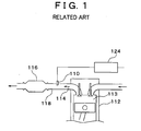
- FIG. 1 is an illustration of an engine exhaust gas purifying apparatus.
- Fig. 2 is a cross-sectional view of an injector and an exhaust passage (a wall on the opposite side of the exhaust passage 118 is omitted in the illustration of Fig. 2. The same applies to the following figures).
- Engine exhaust gas 114 flows from right to left in Fig. 2.
- the injector 110 the right side of the injector 110 corresponds to upstream, and the left side thereof corresponds to downstream in Fig. 2.
- the engine exhaust gas 114 resulting from combustion in a combustion chamber 113 of an engine 112 is discharged into an exhaust passage 118.
- the injector 110 is mounted to the exhaust passage 118.
- a seat 125 is mounted at the tip end of the injector 110 (at the bottom of Fig. 2), and an injection nozzle 125a is formed in the seat 125.
- a communicating passage is formed between a fuel supply port 126 and the seat 125, and compressed fuel is supplied from a fuel pump 124 into the fuel supply port 126.
- the fuel thus injected in a spray form from the injector 110 into the engine exhaust gas 114 flowing through the exhaust passage 118 is mixed with the engine exhaust gas 114, increasing the amount of HC in the exhaust gas 114.
- the engine exhaust gas 114 including the increased amount of HC then passes through a catalytic converter 116, in which NOx is removed from the engine exhaust gas 114 by reduction.
- the engine exhaust gas 114 thus purified is discharged into the atmosphere.
- the injection nozzle 125a formed at the tip of the injector 110 of the conventional engine exhaust gas purifying apparatus is exposed directly to the flow of the engine exhaust gas 114 including fine soot particles. Therefore, during continuous operation of the engine, the soot included in the engine exhaust gas 114 progressively adheres to the injection nozzle 125a, resulting in clogging of the injection nozzle 125a.
- an injector injects a reducing agent into an exhaust passage formed between an engine and a catalytic converter in an engine exhaust gas purifying apparatus for purifying engine exhaust gas by the catalytic converter mounted in the engine exhaust passage.
- the injector includes at a tip end thereof a protector for preventing an injection nozzle of the injector from being directly exposed to an engine exhaust gas flow.
- the protector is provided at the tip end of the injector. Therefore, the injection nozzle is not directly exposed to the engine exhaust gas flow, preventing soot included in the engine exhaust gas from adhering to the injection nozzle.
- This structure is thus capable of preventing clogging of the injection nozzle of the injector resulting from adhesion of the soot.
- the "protector” may be provided in any form as long as it serves to prevent the injection nozzle from being directly exposed to the engine exhaust gas flow.
- the protector may be a means for changing the flowing direction of the exhaust gas around the injection nozzle so that the exhaust gas flow may not directly contact the injection nozzle.
- a flow direction changing means may be a wall provided near the injection nozzle. In this case, the only requirement for the wall is to prevent the injection nozzle from being directly exposed to the engine exhaust gas flow. Therefore, the wall need only be provided at least upstream of the injection nozzle, and does not necessarily entirely surround the injection nozzle.
- the protector in the first aspect, includes an impingement wall on which the reducing agent injected from the injection nozzle impinges.
- the impingement wall on which the reducing agent injected from the injection nozzle impinges is formed in the protector.
- the reducing agent injected from the injection nozzle in a spray form is atomized into finer particles upon impinging on the impingement wall. As a result, the reducing agent is mixed with the engine exhaust gas more uniformly.
- the protector in the first aspect, includes a swirl portion for swirling the reducing agent injected from the injection nozzle.
- the swirl portion for swirling the reducing agent injected from the injection nozzle is formed in the protector.
- the reducing agent injected from the injection nozzle in a spray form thus flows into the engine exhaust gas while being swirled in the swirl portion of the protector. As a result, the reducing agent is mixed with the engine exhaust gas more uniformly.
- the protector may include a wall entirely surrounding the injection nozzle of the injector. Since the injection nozzle is entirely surrounded by the wall, the engine exhaust gas can be prevented from reaching the injection nozzle from the downstream side of the protector. As a result, adhesion of the soot to the injection nozzle can be prevented more reliably.
- a projecting length and an inner diameter of the cylindrical wall of the protector may be set such that the reducing agent injected from the injection nozzle may not contact an inner peripheral surface of the cylindrical wall.
- the injection nozzle may be provided outside an inner wall surface of the exhaust passage so that only the protector projects into the exhaust passage. This prevents the injector body from being exposed to the engine exhaust gas, whereby temperature rise in the injector body can be prevented.
- a wall surface of the impingement wall may be formed such that the reducing agent flows toward the downstream side of the engine exhaust passage after impinging on the impingement wall.
- the injected reducing agent is mixed with the engine exhaust gas without impinging on (adhering to) the wall surface of the exhaust passage (the wall surface facing the injector), enabling efficient reduction of NOx.
- the swirl portion includes a flow path of the reducing agent formed in the protector, the flow path includes an opening formed at one end thereof, and the injection nozzle is connected to the flow path at the other end so that the reducing agent flows into the flow path from a tangential direction thereof.
- the reducing agent introduced into the flow path flows along the wall surface of the flow path, whereby a flow velocity in the swirling direction is applied to the reducing agent.
- the reducing agent is discharged from the opening at the other end of the flow path into the engine exhaust passage. This simplifies the structure of the swirl portion for applying a swirling component.
- the flow path may be tilted with respect to an axial direction of the injector so that the reducing agent discharged from the opening of the swirl portion is directed toward a center of the exhaust passage.
- the flow path may be shaped such that a cross-sectional area thereof is reduced toward its tip end. This increases the flow velocity of the reducing agent discharged from the flow path in the protector, so that the reducing agent is mixed with the engine exhaust gas more uniformly.
- the flow path may be shaped such that a cross-sectional area thereof is increased toward its tip end. This allows the reducing agent to be discharged from the flow path in the protector while diffusing, so that the reducing agent is mixed with the engine exhaust gas more uniformly.
- the protector may be detachably mounted to the injector. This makes it possible to deal with various characteristics of the engine exhaust gas (e.g., flow velocity of the exhaust gas, disturbance of the exhaust gas flow, and the like) by merely replacing the protector. Even if the protector is damaged, the injector does not need to be replaced. Only the protector needs to be replaced.
- various characteristics of the engine exhaust gas e.g., flow velocity of the exhaust gas, disturbance of the exhaust gas flow, and the like
- the protector may include a wall entirely surrounding the injection nozzle of the injector, and the wall may be formed such that a downstream portion thereof is lower in height than an upstream portion thereof with respect to the exhaust gas flow.
- the exhaust gas flows over the upstream portion of the wall. The reducing agent is caught in this flow, and therefore is mixed with the engine exhaust gas more uniformly.
- Fig. 3 is a cross-sectional view of an injector and an exhaust passage.
- Fig. 4 is an enlarged cross-sectional view taken along line IV-IV in Fig. 3, showing a cross section of a protector portion.
- the injector 10 is mounted to an exhaust passage 18 at right angles with the flow of engine exhaust gas 14.
- the exhaust passage 18 provides communication between an engine (not shown) and a catalytic converter (not shown).
- the injector 10 includes a housing 22, a body 36, a valve mechanism (spring 27, valve 32, seat 38 and adjuster 42) mounted within the body 36, a solenoid 34, and the like.
- a cylinder 44 is welded within the housing 22.
- a fuel passage 44a extending in the axial direction thereof.
- the cylindrical adjuster 42 is press-fitted within the passage 44a.
- a non-magnetic member 37 and the body 36 are welded at the tip end of the housing 22 (on the lower side of Fig 3; the opposite side is herein defined as the rear end) .
- the seat 38 is welded to the body 36.
- An injection nozzle 38a is formed in the seat 38.
- the seat 38 has a conical hollow at its rear end.
- a cylindrical protector 38b is formed at the tip end of the seat 38.
- the protector 38b is formed of a cylindrical wall entirely surrounding the injection nozzle 38a, and the tip end thereof is opened to the exhaust passage 18.
- the length from the opening 38c at the tip end to the injection nozzle 38a is determined in view of a fuel injection angle from the injection nozzle 38a. More specifically, this length is determined such that the protector 38b may not prevent diffusion of the fuel injected from the injection nozzle 38a (i.e., such that the diffusing fuel may not contact the inner wall surface of the protector 38b).
- the inner space (fuel flow path) of the protector 38b has a diameter large enough as compared to the cross-sectional area of the injection nozzle 38a (at least twice the diameter of the injection nozzle 38a). This prevents clogging of the opening 38c at the tip end of the protector 38b even when a material such as soot adheres to the tip of the protector 38b.
- the valve 32 is accommodated in the body 36.
- the valve 32 is formed by integrally combining a ball 32a and a shaft 32b.
- the outer peripheral surface of the shaft 32b slides along the inner peripheral surface of the body 36, so that the valve 32 is axially movable within the body 36 (Note that the axial moving distance of the valve 32 is small. Therefore, although not shown in Fig. 3, there is a gap between the rear end face of the shaft 32b and the tip end face of the cylinder 44 while the valve 32 is pressed against the seat 38).
- a fuel passage 32c is formed in the shaft 32b.
- the shaft 32b is formed from a magnetic material, and a fuel passage hole 32d is formed so that the fuel can flow from the inside to the outside of the shaft 32b.
- the spring 27 for providing spring force is inserted between the shaft 32b of the valve 32 and the adjuster 42.
- the spring 27 presses the shaft 32b toward the tip end of the injector the ball 32a is forced into the conical hollow of the seat 38, closing the injection nozzle 38a.
- the force of pressing the ball 32a against the seat 38 can be varied by adjusting the axial position of the adjuster 42 press-fitted within the cylinder 44.
- a fuel supply port 46 is formed in the rear end of the cylinder 44.
- a mesh strainer 48 for capturing foreign matters in the fuel is mounted in the fuel supply port 46. Accordingly, the fuel supplied from the fuel supply port 46 sequentially flows through the strainer 48, passage 44a in the cylinder, passage 42a in the adjuster, passage 32c in the shaft, and fuel passage hole 32d into the seat 38.
- the solenoid 34 is mounted on the outer periphery of the cylinder 44, and a connector 49 for supplying electric power to the solenoid 34 is provided in the housing 22.
- the connector 49 is connected to an electric control circuit (not shown) that controls the fuel injection timing of the injector 10.
- the solenoid 34 When the electric power is supplied through the connector 49, the solenoid 34 is excited, whereby magnetic power is generated.
- the magnetic power thus generated moves the shaft 32b of the valve 32 toward the rear end of the injector.
- the ball 32a integrally formed with the shaft 32b also moves in the same direction, producing a gap between the ball 32a and the seat 38.
- the fuel passes through the gap and is injected from the injection nozzle 38a.
- the fuel 52 thus injected from the injection nozzle 38a diffuses within the protector portion 38b in a spray form, and flows into the exhaust passage 18 from the opening 38c. As a result, the fuel 52 is mixed with the engine exhaust gas 14.
- the injection nozzle 38a is surrounded by the cylindrical protector 38b. Therefore, the engine exhaust gas 14 flowing toward the injection nozzle 38a impinges on the outer wall surface of the protector 38b (i.e., on a portion of the outer wall surface located upstream of the engine exhaust gas 14). As a result, the flow direction of the engine exhaust gas 14 is changed so that the engine exhaust gas 14 flows downstream along the outer wall of the protector 38b. Accordingly, the injection nozzle 38a is not directly exposed to the engine exhaust gas 14, preventing clogging of the injection nozzle 38a resulting from adhesion of the soot included in the engine exhaust gas 14.
- FIG. 5 is a cross-sectional view of the tip end portion of the injector and the exhaust passage. Note that, in Fig. 5, the members having the same function as those in Fig. 3 are denoted with the same reference numerals and characters as those in Fig. 3, and description thereof is omitted (the same applies to the third embodiment described below).
- a protector 53b has a cylindrical shape with its tip end closed.
- An impingement wall 53c is formed at the tip end of the protector 53b (i.e., at the location facing an injection nozzle 53a) so that injected fuel 55 impinges thereon.
- the impingement wall 53c is tilted with respect to the axial direction of the injector 10a.
- the tilt angle of the impingement wall 53c is determined such that the fuel impinging on the impingement wall 53c is directed toward the downstream side of the engine exhaust gas 14 and toward the center of the exhaust passage 18.
- an opening 53d for discharging the fuel from the protector 53b into the exhaust passage 18 is formed in the tip end portion of the downstream sidewall (located downstream of the engine exhaust gas 14) of the protector 53b.
- the opening 53d is sized so that the fuel flow may not impinge on the inner wall of the protector 53b after impinging on the impingement wall 53c.
- the fuel 55 injected from the injection nozzle 53a in a spray form is atomized into finer particles when impinging on the impingement wall 53c.
- the fuel 55 is directed toward the downstream side of the engine exhaust gas 14 and toward the center of the exhaust passage 18.
- the fuel 55 is thus discharged from the opening 53d formed in the tip end portion of the sidewall of the protector 53b into the exhaust passage 18, and is mixed with the engine exhaust gas 14. Since the fuel flow is discharged from the protector 53b into the exhaust passage 18 as finer particles after impinging on the impingement wall 53c, the fuel is mixed with the engine exhaust gas 14 more uniformly.
- the fuel discharged from the protector 53b flows in the same direction as that of the engine exhaust gas 14 toward the center of the exhaust passage, it is efficiently mixed with the engine exhaust gas 14 without-adhering to the inner wall surface of the exhaust passage 18.
- Fig. 6 is a cross-sectional view of the tip end portion of the injector and the exhaust passage.
- Fig. 7 is an enlarged cross-sectional view taken along line VII-VII in Fig. 6, showing a cross section of a swirl portion.
- a swirl portion 56c for swirling fuel 58 injected from an injection nozzle 56a is formed in a protector 56b.
- the swirl portion 56c is a cylindrical fuel flow path.
- the injection nozzle 56a is provided at one end (upstream end) of the fuel flow path such that the fuel is introduced into the fuel flow path from the tangential direction thereof (the tangential direction of the fuel flow path) .
- the other end (downstream end) of the fuel flow path is opened to the exhaust passage 18.
- the swirl portion 56c (fuel flow path) is tilted with respect to the axial direction of the injector 10b.
- the tilt angle is determined such that the fuel discharged from an opening 56d of the swirl portion 56c flows toward the downstream side of the engine exhaust gas 14 and toward the center of the exhaust passage 18.
- the fuel 58 injected from the injection nozzle 56a swirls along the inner periphery of the cylindrical swirl portion 56c.
- the swirling fuel 58 is then discharged from the opening 56d of the swirl portion 56c into the engine exhaust gas 14.
- the swirling fuel 58 is thus vigorously mixed with the engine exhaust gas 14. As a result, the fuel is mixed with the engine fuel 14 more uniformly.
- the impingement wall 53c of the injector 10a in the second embodiment does not necessarily have a flat surface.
- the impingement wall 53c may have a curved surface or combination of any of various curved surfaces and various flat surfaces in order to facilitate atomization of the fuel, to adjust the flow direction thereof, and the like.
- the swirl portion 56c of the injector 10b in the third embodiment may have a narrowed opening 56e as shown in Fig. 8. Such a narrowed opening 56e allows the fuel injected from the injection nozzle 56a to be vigorously mixed with the exhaust gas.
- the swirl portion 56c may have an enlarged opening 56f as shown in Fig. 9. Such an enlarged opening 56f allows the fuel injected from the injection nozzle 56a to be mixed with the exhaust gas while diffusing.
- the structure of the swirl portion formed in the injector is not limited to that described in the third embodiment.
- the swirl portion may have any structure as long as it applies a velocity component of the swirling direction to the fuel flow discharged from the opening of the protector.
- a swirl vane may be provided at the opening of the protector so as to apply a velocity component of the swirling direction to the fuel flow discharged from the opening of the protector.
- an injection nozzle 62a of a seat 62 may be oriented toward the downstream side of the engine exhaust gas 14 so that an opening of a protector portion 62b is opened downstream.
- the injection nozzle 62a is oriented toward the downstream side of the engine exhaust gas 14, and also surrounded by the protector portion 62b. Accordingly, adhesion of the soot to the injection nozzle 62a can be prevented more reliably.
- an injection nozzle 72a of a seat 72 may be formed outside the exhaust passage 18 so that only a protector 72b projects into the exhaust passage 18. In this structure, the injector body is not exposed to the engine exhaust gas 14, whereby temperature rise in the injector body can be prevented.
- the wall of a protector 82b entirely surrounding an injection nozzle 82a may be formed such that a downstream portion 82c of the wall is lower in height than an upstream portion 82d thereof.
- the exhaust gas flows over the upstream portion 82d of the wall. The reducing agent is caught in this flow, and therefore is mixed with the engine exhaust gas more uniformly.
- the protector described in the first to third embodiments surrounds the injection nozzle, it does not necessarily have such a structure. Adhesion of the soot to the injection nozzle can be prevented as long as a protector (wall) is provided at least on the upstream side of the injection nozzle.
- An injector (10) injects a reducing agent (52) into an exhaust passage (18) formed between an engine and a catalytic converter in an engine exhaust gas purifying apparatus for purifying engine exhaust gas using the catalytic converter mounted in the exhaust passage (18) of the engine.
- the injector (10) includes at a tip end thereof a protector (38b) for preventing an injection nozzle (38a) of the injector from being directly exposed to an engine exhaust gas flow (14).
Landscapes
- Chemical & Material Sciences (AREA)
- Engineering & Computer Science (AREA)
- Chemical Kinetics & Catalysis (AREA)
- Health & Medical Sciences (AREA)
- Combustion & Propulsion (AREA)
- Toxicology (AREA)
- Mechanical Engineering (AREA)
- General Engineering & Computer Science (AREA)
- Biomedical Technology (AREA)
- Environmental & Geological Engineering (AREA)
- Analytical Chemistry (AREA)
- General Chemical & Material Sciences (AREA)
- Oil, Petroleum & Natural Gas (AREA)
- Exhaust Gas After Treatment (AREA)
Abstract
Description
- The invention generally relates to an injector for an engine exhaust gas purifying apparatus. More particularly, the invention relates to art for preventing a material such as soot from adhering to an injection nozzle of the injector.
- The exhaust gas discharged directly from an engine includes nitrogen oxides (hereinafter, simply referred to as NOx). Since NOx pollutes the atmosphere, the exhaust gas must be purified before being discharged into the atmosphere. Removing NOx with a catalytic converter using hydrocarbon (hereinafter, simply referred to as HC) as a reducing agent is known as a technique of removing NOx in the exhaust gas. HC is also included in the engine exhaust gas, but the amount thereof is small (particularly small in a diesel engine), resulting in poor reduction efficiency of the catalytic converter. In view of this, art for improving the reduction efficiency of the catalytic converter is described in, e.g., Japanese Patent Laid-Open Publication No. 4-358716. In this art, a reducing agent (e.g., engine fuel, alcohol or the like) is introduced into the engine exhaust gas so as to increase the amount of HC, thereby improving the reduction efficiency of the catalytic converter.
- An exemplary engine exhaust gas purifying apparatus regarding the above related art will now be described with reference to Figs. 1 and 2. Fig. 1 is an illustration of an engine exhaust gas purifying apparatus. Fig. 2 is a cross-sectional view of an injector and an exhaust passage (a wall on the opposite side of the
exhaust passage 118 is omitted in the illustration of Fig. 2. The same applies to the following figures).Engine exhaust gas 114 flows from right to left in Fig. 2. For theinjector 110, the right side of theinjector 110 corresponds to upstream, and the left side thereof corresponds to downstream in Fig. 2. - As shown in Fig. 1, the
engine exhaust gas 114 resulting from combustion in acombustion chamber 113 of anengine 112 is discharged into anexhaust passage 118. Theinjector 110 is mounted to theexhaust passage 118. As shown in Fig. 2, aseat 125 is mounted at the tip end of the injector 110 (at the bottom of Fig. 2), and aninjection nozzle 125a is formed in theseat 125. A communicating passage is formed between afuel supply port 126 and theseat 125, and compressed fuel is supplied from afuel pump 124 into thefuel supply port 126. While asolenoid 134 is not excited, aball 132a mounted at the tip end of avalve 132 is pressed against theseat 125 by aspring 127, closing theinjection nozzle 125a. When thesolenoid 134 is excited by electric power supplied from an electric control circuit (not shown) controlling the engine exhaust gas purifying apparatus, magnetic force is generated, whereby thevalve 132 is moved upward in Fig. 2. As a result, a gap is produced between theball 132a of thevalve 132 and theseat 125, and the fuel is injected from theinjection nozzle 125a into theexhaust passage 118. - The fuel thus injected in a spray form from the
injector 110 into theengine exhaust gas 114 flowing through theexhaust passage 118 is mixed with theengine exhaust gas 114, increasing the amount of HC in theexhaust gas 114. Theengine exhaust gas 114 including the increased amount of HC then passes through acatalytic converter 116, in which NOx is removed from theengine exhaust gas 114 by reduction. Theengine exhaust gas 114 thus purified is discharged into the atmosphere. - The
injection nozzle 125a formed at the tip of theinjector 110 of the conventional engine exhaust gas purifying apparatus is exposed directly to the flow of theengine exhaust gas 114 including fine soot particles. Therefore, during continuous operation of the engine, the soot included in theengine exhaust gas 114 progressively adheres to theinjection nozzle 125a, resulting in clogging of theinjection nozzle 125a. - It is an object of the invention to provide an injector capable of preventing clogging of an injection nozzle resulting from adhesion of soot.
- According to a first aspect of the invention, an injector injects a reducing agent into an exhaust passage formed between an engine and a catalytic converter in an engine exhaust gas purifying apparatus for purifying engine exhaust gas by the catalytic converter mounted in the engine exhaust passage. The injector includes at a tip end thereof a protector for preventing an injection nozzle of the injector from being directly exposed to an engine exhaust gas flow.
- According to the injector, the protector is provided at the tip end of the injector. Therefore, the injection nozzle is not directly exposed to the engine exhaust gas flow, preventing soot included in the engine exhaust gas from adhering to the injection nozzle. This structure is thus capable of preventing clogging of the injection nozzle of the injector resulting from adhesion of the soot.
- The "protector" may be provided in any form as long as it serves to prevent the injection nozzle from being directly exposed to the engine exhaust gas flow. For example, the protector may be a means for changing the flowing direction of the exhaust gas around the injection nozzle so that the exhaust gas flow may not directly contact the injection nozzle. Typically, such a flow direction changing means may be a wall provided near the injection nozzle. In this case, the only requirement for the wall is to prevent the injection nozzle from being directly exposed to the engine exhaust gas flow. Therefore, the wall need only be provided at least upstream of the injection nozzle, and does not necessarily entirely surround the injection nozzle.
- According to a second aspect of the invention, in the first aspect, the protector includes an impingement wall on which the reducing agent injected from the injection nozzle impinges.
- In the injector, the impingement wall on which the reducing agent injected from the injection nozzle impinges is formed in the protector. The reducing agent injected from the injection nozzle in a spray form is atomized into finer particles upon impinging on the impingement wall. As a result, the reducing agent is mixed with the engine exhaust gas more uniformly.
- According to a third aspect of the invention, in the first aspect, the protector includes a swirl portion for swirling the reducing agent injected from the injection nozzle.
- In the injector, the swirl portion for swirling the reducing agent injected from the injection nozzle is formed in the protector. The reducing agent injected from the injection nozzle in a spray form thus flows into the engine exhaust gas while being swirled in the swirl portion of the protector. As a result, the reducing agent is mixed with the engine exhaust gas more uniformly.
- In any one of the first to third aspects, the protector may include a wall entirely surrounding the injection nozzle of the injector. Since the injection nozzle is entirely surrounded by the wall, the engine exhaust gas can be prevented from reaching the injection nozzle from the downstream side of the protector. As a result, adhesion of the soot to the injection nozzle can be prevented more reliably. A projecting length and an inner diameter of the cylindrical wall of the protector may be set such that the reducing agent injected from the injection nozzle may not contact an inner peripheral surface of the cylindrical wall.
- In the injector according to any one of the first to third aspects, the injection nozzle may be provided outside an inner wall surface of the exhaust passage so that only the protector projects into the exhaust passage. This prevents the injector body from being exposed to the engine exhaust gas, whereby temperature rise in the injector body can be prevented.
- In the second aspect, a wall surface of the impingement wall may be formed such that the reducing agent flows toward the downstream side of the engine exhaust passage after impinging on the impingement wall. In this case, the injected reducing agent is mixed with the engine exhaust gas without impinging on (adhering to) the wall surface of the exhaust passage (the wall surface facing the injector), enabling efficient reduction of NOx.
- According to a fourth aspect of the invention, in the third aspect, the swirl portion includes a flow path of the reducing agent formed in the protector, the flow path includes an opening formed at one end thereof, and the injection nozzle is connected to the flow path at the other end so that the reducing agent flows into the flow path from a tangential direction thereof. In this case, the reducing agent introduced into the flow path flows along the wall surface of the flow path, whereby a flow velocity in the swirling direction is applied to the reducing agent. As a result, the reducing agent is discharged from the opening at the other end of the flow path into the engine exhaust passage. This simplifies the structure of the swirl portion for applying a swirling component.
- In the fourth aspect, the flow path may be tilted with respect to an axial direction of the injector so that the reducing agent discharged from the opening of the swirl portion is directed toward a center of the exhaust passage.
- In the fourth aspect, the flow path may be shaped such that a cross-sectional area thereof is reduced toward its tip end. This increases the flow velocity of the reducing agent discharged from the flow path in the protector, so that the reducing agent is mixed with the engine exhaust gas more uniformly.
- In the fourth aspect, the flow path may be shaped such that a cross-sectional area thereof is increased toward its tip end. This allows the reducing agent to be discharged from the flow path in the protector while diffusing, so that the reducing agent is mixed with the engine exhaust gas more uniformly.
- In any one of the first to third aspects, the protector may be detachably mounted to the injector. This makes it possible to deal with various characteristics of the engine exhaust gas (e.g., flow velocity of the exhaust gas, disturbance of the exhaust gas flow, and the like) by merely replacing the protector. Even if the protector is damaged, the injector does not need to be replaced. Only the protector needs to be replaced.
- In the first aspect, the protector may include a wall entirely surrounding the injection nozzle of the injector, and the wall may be formed such that a downstream portion thereof is lower in height than an upstream portion thereof with respect to the exhaust gas flow. In this case, the exhaust gas flows over the upstream portion of the wall. The reducing agent is caught in this flow, and therefore is mixed with the engine exhaust gas more uniformly.
-
- Fig. 1 is an illustration of a conventional engine exhaust gas purifying apparatus;
- Fig. 2 is a cross-sectional view of a conventional injector and an exhaust passage;
- Fig. 3 is a cross-sectional view of an injector according to a first embodiment of the invention and an exhaust passage;
- Fig. 4 is an enlarged cross-sectional view taken along line IV-IV in Fig. 3, showing a cross section of a protector portion;
- Fig. 5 is a cross-sectional view of the tip end portion of an injector according to a second embodiment of the invention and an exhaust passage;
- Fig. 6 is a cross-sectional view of the tip end portion of an injector according to a third embodiment of the invention and an exhaust passage;
- Fig. 7 is an enlarged cross-sectional view taken along line VII-VII in Fig. 6, showing a cross section of a swirl portion;
- Fig. 8 shows a narrowed opening of the swirl portion in a modification of the third embodiment;
- Fig. 9 shows an enlarged opening of the swirl portion in a modification of the third embodiment;
- Fig. 10 shows a modification of an embodiment of the invention, in which an injection nozzle is oriented downstream;
- Fig. 11 shows a modification of an embodiment of the invention, in which an injection nozzle is formed outside the exhaust passage; and
- Fig. 12 shows a modification of an embodiment of the invention, in which the height of a protector wall is lower on the downstream side than on the upstream side.
-
- Hereinafter, an injector according to the first embodiment of the invention will be described with reference to Figs. 3 and 4. Fig. 3 is a cross-sectional view of an injector and an exhaust passage. Fig. 4 is an enlarged cross-sectional view taken along line IV-IV in Fig. 3, showing a cross section of a protector portion.
- As shown in Fig. 3, the
injector 10 is mounted to anexhaust passage 18 at right angles with the flow ofengine exhaust gas 14. Theexhaust passage 18 provides communication between an engine (not shown) and a catalytic converter (not shown). - The
injector 10 includes ahousing 22, abody 36, a valve mechanism (spring 27,valve 32,seat 38 and adjuster 42) mounted within thebody 36, asolenoid 34, and the like. - As shown in Fig. 3, a
cylinder 44 is welded within thehousing 22. In thecylinder 44 is formed afuel passage 44a extending in the axial direction thereof. Thecylindrical adjuster 42 is press-fitted within thepassage 44a. Anon-magnetic member 37 and thebody 36 are welded at the tip end of the housing 22 (on the lower side of Fig 3; the opposite side is herein defined as the rear end) . Theseat 38 is welded to thebody 36. Aninjection nozzle 38a is formed in theseat 38. Theseat 38 has a conical hollow at its rear end. Acylindrical protector 38b is formed at the tip end of theseat 38. - The
protector 38b is formed of a cylindrical wall entirely surrounding theinjection nozzle 38a, and the tip end thereof is opened to theexhaust passage 18. The length from theopening 38c at the tip end to theinjection nozzle 38a is determined in view of a fuel injection angle from theinjection nozzle 38a. More specifically, this length is determined such that theprotector 38b may not prevent diffusion of the fuel injected from theinjection nozzle 38a (i.e., such that the diffusing fuel may not contact the inner wall surface of theprotector 38b). The inner space (fuel flow path) of theprotector 38b has a diameter large enough as compared to the cross-sectional area of theinjection nozzle 38a (at least twice the diameter of theinjection nozzle 38a). This prevents clogging of theopening 38c at the tip end of theprotector 38b even when a material such as soot adheres to the tip of theprotector 38b. - The
valve 32 is accommodated in thebody 36. Thevalve 32 is formed by integrally combining aball 32a and ashaft 32b. The outer peripheral surface of theshaft 32b slides along the inner peripheral surface of thebody 36, so that thevalve 32 is axially movable within the body 36 (Note that the axial moving distance of thevalve 32 is small. Therefore, although not shown in Fig. 3, there is a gap between the rear end face of theshaft 32b and the tip end face of thecylinder 44 while thevalve 32 is pressed against the seat 38). Afuel passage 32c is formed in theshaft 32b. Theshaft 32b is formed from a magnetic material, and afuel passage hole 32d is formed so that the fuel can flow from the inside to the outside of theshaft 32b. Thespring 27 for providing spring force is inserted between theshaft 32b of thevalve 32 and theadjuster 42. When thespring 27 presses theshaft 32b toward the tip end of the injector, theball 32a is forced into the conical hollow of theseat 38, closing theinjection nozzle 38a. The force of pressing theball 32a against theseat 38 can be varied by adjusting the axial position of theadjuster 42 press-fitted within thecylinder 44. - A
fuel supply port 46 is formed in the rear end of thecylinder 44. Amesh strainer 48 for capturing foreign matters in the fuel is mounted in thefuel supply port 46. Accordingly, the fuel supplied from thefuel supply port 46 sequentially flows through thestrainer 48,passage 44a in the cylinder,passage 42a in the adjuster,passage 32c in the shaft, andfuel passage hole 32d into theseat 38. - The
solenoid 34 is mounted on the outer periphery of thecylinder 44, and aconnector 49 for supplying electric power to thesolenoid 34 is provided in thehousing 22. Theconnector 49 is connected to an electric control circuit (not shown) that controls the fuel injection timing of theinjector 10. - Hereinafter, operation of the
injector 10 will be described. - While the electric power is not supplied through the
connector 49 and thus thesolenoid 34 is not excited, thespring 27 presses theball 32a of thevalve 32 against theseat 38. In this state, theinjection nozzle 38a is closed, and the compressed fuel already supplied from a fuel pump down to theseat 38 through thefuel supply port 46 is not injected. - When the electric power is supplied through the
connector 49, thesolenoid 34 is excited, whereby magnetic power is generated. The magnetic power thus generated moves theshaft 32b of thevalve 32 toward the rear end of the injector. As a result, theball 32a integrally formed with theshaft 32b also moves in the same direction, producing a gap between theball 32a and theseat 38. The fuel passes through the gap and is injected from theinjection nozzle 38a. - The
fuel 52 thus injected from theinjection nozzle 38a diffuses within theprotector portion 38b in a spray form, and flows into theexhaust passage 18 from theopening 38c. As a result, thefuel 52 is mixed with theengine exhaust gas 14. - The fuel thus injected from the
injection nozzle 38a does not impinge on the inner wall surface of theprotector portion 38b (since the length of theprotector portion 38 is adjusted as such). Therefore, the fuel discharged from theopening 38c of theprotector portion 38b is efficiently diffused within theexhaust passage 18, and is mixed with theengine exhaust gas 14. As shown in Figs. 3 and 4, theinjection nozzle 38a is surrounded by thecylindrical protector 38b. Therefore, theengine exhaust gas 14 flowing toward theinjection nozzle 38a impinges on the outer wall surface of theprotector 38b (i.e., on a portion of the outer wall surface located upstream of the engine exhaust gas 14). As a result, the flow direction of theengine exhaust gas 14 is changed so that theengine exhaust gas 14 flows downstream along the outer wall of theprotector 38b. Accordingly, theinjection nozzle 38a is not directly exposed to theengine exhaust gas 14, preventing clogging of theinjection nozzle 38a resulting from adhesion of the soot included in theengine exhaust gas 14. - Hereinafter, an injector according to the second embodiment of the invention will be described with reference to Fig. 5. Fig. 5 is a cross-sectional view of the tip end portion of the injector and the exhaust passage. Note that, in Fig. 5, the members having the same function as those in Fig. 3 are denoted with the same reference numerals and characters as those in Fig. 3, and description thereof is omitted (the same applies to the third embodiment described below).
- As shown in Fig. 5, in the
injector 10a of the second embodiment, aprotector 53b has a cylindrical shape with its tip end closed. Animpingement wall 53c is formed at the tip end of theprotector 53b (i.e., at the location facing aninjection nozzle 53a) so that injectedfuel 55 impinges thereon. Theimpingement wall 53c is tilted with respect to the axial direction of theinjector 10a. The tilt angle of theimpingement wall 53c is determined such that the fuel impinging on theimpingement wall 53c is directed toward the downstream side of theengine exhaust gas 14 and toward the center of theexhaust passage 18. - Corresponding to the
impingement wall 53c, anopening 53d for discharging the fuel from theprotector 53b into theexhaust passage 18 is formed in the tip end portion of the downstream sidewall (located downstream of the engine exhaust gas 14) of theprotector 53b. Theopening 53d is sized so that the fuel flow may not impinge on the inner wall of theprotector 53b after impinging on theimpingement wall 53c. - In the
injector 10a having such a structure, thefuel 55 injected from theinjection nozzle 53a in a spray form is atomized into finer particles when impinging on theimpingement wall 53c. As a result, thefuel 55 is directed toward the downstream side of theengine exhaust gas 14 and toward the center of theexhaust passage 18. Thefuel 55 is thus discharged from theopening 53d formed in the tip end portion of the sidewall of theprotector 53b into theexhaust passage 18, and is mixed with theengine exhaust gas 14. Since the fuel flow is discharged from theprotector 53b into theexhaust passage 18 as finer particles after impinging on theimpingement wall 53c, the fuel is mixed with theengine exhaust gas 14 more uniformly. Moreover, since the fuel discharged from theprotector 53b flows in the same direction as that of theengine exhaust gas 14 toward the center of the exhaust passage, it is efficiently mixed with theengine exhaust gas 14 without-adhering to the inner wall surface of theexhaust passage 18. - Hereinafter, an injector according to the third embodiment of the invention will now be described with reference to Figs. 6 and 7. Fig. 6 is a cross-sectional view of the tip end portion of the injector and the exhaust passage.
- Fig. 7 is an enlarged cross-sectional view taken along line VII-VII in Fig. 6, showing a cross section of a swirl portion.
- In the
injector 10b according to the third embodiment, aswirl portion 56c for swirlingfuel 58 injected from aninjection nozzle 56a is formed in aprotector 56b. As shown in Figs. 6 and 7, theswirl portion 56c is a cylindrical fuel flow path. Theinjection nozzle 56a is provided at one end (upstream end) of the fuel flow path such that the fuel is introduced into the fuel flow path from the tangential direction thereof (the tangential direction of the fuel flow path) . The other end (downstream end) of the fuel flow path is opened to theexhaust passage 18. Theswirl portion 56c (fuel flow path) is tilted with respect to the axial direction of theinjector 10b. Like the second embodiment, the tilt angle is determined such that the fuel discharged from anopening 56d of theswirl portion 56c flows toward the downstream side of theengine exhaust gas 14 and toward the center of theexhaust passage 18. - In such an
injector 10b, thefuel 58 injected from theinjection nozzle 56a swirls along the inner periphery of thecylindrical swirl portion 56c. The swirlingfuel 58 is then discharged from theopening 56d of theswirl portion 56c into theengine exhaust gas 14. The swirlingfuel 58 is thus vigorously mixed with theengine exhaust gas 14. As a result, the fuel is mixed with theengine fuel 14 more uniformly. - Although the injector according to some embodiments of the invention has been described, the invention is not limited to the above embodiments and can be embodied in numerous modified and improved forms based on the knowledge of those skilled in the art.
- For example, the
impingement wall 53c of theinjector 10a in the second embodiment does not necessarily have a flat surface. Theimpingement wall 53c may have a curved surface or combination of any of various curved surfaces and various flat surfaces in order to facilitate atomization of the fuel, to adjust the flow direction thereof, and the like. - The
swirl portion 56c of theinjector 10b in the third embodiment may have a narrowed opening 56e as shown in Fig. 8. Such a narrowed opening 56e allows the fuel injected from theinjection nozzle 56a to be vigorously mixed with the exhaust gas. Alternatively, theswirl portion 56c may have anenlarged opening 56f as shown in Fig. 9. Such anenlarged opening 56f allows the fuel injected from theinjection nozzle 56a to be mixed with the exhaust gas while diffusing. The structure of the swirl portion formed in the injector is not limited to that described in the third embodiment. The swirl portion may have any structure as long as it applies a velocity component of the swirling direction to the fuel flow discharged from the opening of the protector. For example, a swirl vane may be provided at the opening of the protector so as to apply a velocity component of the swirling direction to the fuel flow discharged from the opening of the protector. - Like an
injector 10c shown in Fig. 10, aninjection nozzle 62a of aseat 62 may be oriented toward the downstream side of theengine exhaust gas 14 so that an opening of aprotector portion 62b is opened downstream. In this structure, theinjection nozzle 62a is oriented toward the downstream side of theengine exhaust gas 14, and also surrounded by theprotector portion 62b.
Accordingly, adhesion of the soot to theinjection nozzle 62a can be prevented more reliably. - Alternatively, like an
injector 10d shown in Fig. 11, aninjection nozzle 72a of aseat 72 may be formed outside theexhaust passage 18 so that only aprotector 72b projects into theexhaust passage 18. In this structure, the injector body is not exposed to theengine exhaust gas 14, whereby temperature rise in the injector body can be prevented. - Alternatively, like an
injector 10e shown in Fig. 12, the wall of aprotector 82b entirely surrounding aninjection nozzle 82a may be formed such that adownstream portion 82c of the wall is lower in height than anupstream portion 82d thereof. In this structure, the exhaust gas flows over theupstream portion 82d of the wall. The reducing agent is caught in this flow, and therefore is mixed with the engine exhaust gas more uniformly. - Although the protector described in the first to third embodiments surrounds the injection nozzle, it does not necessarily have such a structure. Adhesion of the soot to the injection nozzle can be prevented as long as a protector (wall) is provided at least on the upstream side of the injection nozzle.
- An injector (10) injects a reducing agent (52) into an exhaust passage (18) formed between an engine and a catalytic converter in an engine exhaust gas purifying apparatus for purifying engine exhaust gas using the catalytic converter mounted in the exhaust passage (18) of the engine. The injector (10) includes at a tip end thereof a protector (38b) for preventing an injection nozzle (38a) of the injector from being directly exposed to an engine exhaust gas flow (14).
Claims (13)
- An injector (10, 10a, 10b, 10c, 10d, 10e) for injecting a reducing agent into an exhaust passage (18) formed between an engine and a catalytic converter in an engine exhaust gas purifying apparatus for purifying engine exhaust gas by the catalytic converter mounted in the engine exhaust passage (18), wherein the reducing agent injected from the injector (10, 10a, 10b, 10c, 10d, 10e) flows into the engine exhaust gas and is mixed with the engine exhaust gas,
wherein the injector (10, 10a, 10b, 10c, 10d, 10e) includes at a tip end thereof a protector (38b, 53b, 56b, 62b, 72b, 82b) for preventing an injection nozzle (38a, 53a, 56a, 62a, 72a, 82a) of the injector (10, 10a, 10b, 10c, 10d, 10e) from being directly exposed to an engine exhaust gas flow. - The injector according to claim 1, characterized in that the protector (53b) includes an impingement wall (53c)on which the reducing agent injected from the injection nozzle (53a) impinges.
- The injector according to claim 1, characterized in that the protector (56b) includes a swirl portion (56c) for swirling the reducing agent injected from the injection nozzle (56a).
- The injector according to any one of claims 1 to 3, characterized in that the protector (38b) includes a cylindrical wall projecting along an axis of the injector (10) so as to entirely surround the injection nozzle (38a) of the injector (10).
- The injector according to claim 4, characterized in that a projecting length and an inner diameter of the cylindrical wall of the protector (38b) are set such that the reducing agent injected from the injection nozzle (38a) may not contact an inner peripheral surface of the cylindrical wall.
- The injector according to any one of claims 1 to 3, characterized in that the injection nozzle (72a) is provided outside an inner wall surface of the exhaust passage so that only the protector (72b) projects into the exhaust passage (18).
- The injector according to claim 2, characterized in that a wall surface of the impingement wall (53c) is formed such that the reducing agent flows toward a downstream side of the engine exhaust passage (18) after impinging on the impingement wall (53c).
- The injector according to claim 7, characterized in that the impingement wall (53c) is tilted with respect to an axial direction of the injector (10a) so that the reducing agent atomized by impingement on the impingement wall (53c) is directed toward a downstream side of the exhaust gas and toward a center of the exhaust passage (18).
- The injector according to claim 3, characterized in that the swirl portion (56c) includes a flow path of the reducing agent formed in the protector (56b), the flow path includes an opening (56d) at one end thereof, and the injection nozzle (56a) is connected to the flow path at the other end so that the reducing agent flows into the flow path from a tangential direction thereof.
- The injector according to claim 9, characterized in that the flow path is tilted with respect to an axial direction of the injector (10b) so that the reducing agent discharged from the opening (56d) of the swirl portion (56c) is directed toward a center of the exhaust passage (18).
- The injector according to claim 9, characterized in that the flow path is shaped such that a cross-sectional area thereof is reduced toward its tip end.
- The injector according to claim 9, characterized in that the flow path is shaped such that a cross-sectional area thereof is increased toward its tip end.
- The injector according to any one of claims 1 to 3, characterized in that the protector (38b, 53b, 56b, 62b, 72b, 82b) is detachably mounted to the injector (10, 10a, 10b, 10c, 10d, 10e).
Priority Applications (3)
| Application Number | Priority Date | Filing Date | Title |
|---|---|---|---|
| EP01128129A EP1314864B1 (en) | 2001-11-27 | 2001-11-27 | Injector for engine exhaust gas purifying apparatus |
| DE60125786T DE60125786T2 (en) | 2001-11-27 | 2001-11-27 | Injection valve for an exhaust gas purification device |
| ES01128129T ES2278677T3 (en) | 2001-11-27 | 2001-11-27 | INJECTOR FOR PURIFICATION APPLIANCE OF EXHAUST GASES OF AN ENGINE. |
Applications Claiming Priority (1)
| Application Number | Priority Date | Filing Date | Title |
|---|---|---|---|
| EP01128129A EP1314864B1 (en) | 2001-11-27 | 2001-11-27 | Injector for engine exhaust gas purifying apparatus |
Publications (2)
| Publication Number | Publication Date |
|---|---|
| EP1314864A1 true EP1314864A1 (en) | 2003-05-28 |
| EP1314864B1 EP1314864B1 (en) | 2007-01-03 |
Family
ID=8179355
Family Applications (1)
| Application Number | Title | Priority Date | Filing Date |
|---|---|---|---|
| EP01128129A Expired - Lifetime EP1314864B1 (en) | 2001-11-27 | 2001-11-27 | Injector for engine exhaust gas purifying apparatus |
Country Status (3)
| Country | Link |
|---|---|
| EP (1) | EP1314864B1 (en) |
| DE (1) | DE60125786T2 (en) |
| ES (1) | ES2278677T3 (en) |
Cited By (16)
| Publication number | Priority date | Publication date | Assignee | Title |
|---|---|---|---|---|
| EP1698768A1 (en) * | 2005-03-02 | 2006-09-06 | Hydraulik-Ring Gmbh | Injection device for the treatment of exhaust fumes motor vehicles |
| FR2897644A1 (en) * | 2006-02-20 | 2007-08-24 | Renault Sas | DEVICE FOR DEPOLLUTING THE EXHAUST GASES OF AN INTERNAL COMBUSTION ENGINE |
| FR2900439A3 (en) | 2006-04-27 | 2007-11-02 | Renault Sas | INJECTION DEVICE WITH A MIXER OBSTACLE IN THE EXHAUST PIPE |
| FR2900962A1 (en) | 2006-05-15 | 2007-11-16 | Renault Sas | EXHAUST LINE COMPRISING A FUEL INJECTOR AND A PLATE SUITABLE FOR VAPORIZING THE FUEL INJECTED ON SAID PLATE |
| EP2282028A1 (en) * | 2009-06-30 | 2011-02-09 | Kabushiki Kaisha Toyota Jidoshokki | Exhaust gas purification apparatus |
| EP2492465A1 (en) * | 2011-02-25 | 2012-08-29 | Peugeot Citroën Automobiles SA | Device for protecting a reducer injector |
| JP2013002398A (en) * | 2011-06-17 | 2013-01-07 | Mitsubishi Motors Corp | Exhaust emission control device |
| WO2013113881A1 (en) * | 2012-02-03 | 2013-08-08 | Emitec Gesellschaft Für Emissionstechnologie Mbh | Dosing valve for additives at risk of freezing |
| US9657624B2 (en) | 2007-07-24 | 2017-05-23 | Faurecia Emissions Control Technologies, Germany Gmbh | Assembly and method for introducing a reducing agent into the exhaust pipe of an exhaust system of an internal combustion engine |
| US9714598B2 (en) | 2015-04-30 | 2017-07-25 | Faurecia Emissions Control Technologies, Usa, Llc | Mixer with integrated doser cone |
| US9719397B2 (en) | 2015-04-30 | 2017-08-01 | Faurecia Emissions Control Technologies Usa, Llc | Mixer with integrated doser cone |
| US9726064B2 (en) | 2015-04-30 | 2017-08-08 | Faurecia Emissions Control Technologies, Usa, Llc | Mixer for use in a vehicle exhaust system |
| US9828897B2 (en) | 2015-04-30 | 2017-11-28 | Faurecia Emissions Control Technologies Usa, Llc | Mixer for a vehicle exhaust system |
| US10787946B2 (en) | 2018-09-19 | 2020-09-29 | Faurecia Emissions Control Technologies, Usa, Llc | Heated dosing mixer |
| US10920635B2 (en) | 2019-04-23 | 2021-02-16 | Faurecia Emissions Control Technologies, Usa, Llc | Exhaust gas aftertreatment system with a reducing agent mixer having an injector tip protector |
| US10933387B2 (en) | 2016-10-21 | 2021-03-02 | Faurecia Emissions Control Technologies, Usa, Llc | Reducing agent mixer |
Families Citing this family (6)
| Publication number | Priority date | Publication date | Assignee | Title |
|---|---|---|---|---|
| DE102004025062B4 (en) | 2004-05-18 | 2006-09-14 | Hydraulik-Ring Gmbh | Freezer-compatible metering valve |
| DE102007004687B4 (en) | 2007-01-25 | 2012-03-01 | Hydraulik-Ring Gmbh | Volume quantity dispensing unit and method for calibrating the pressure output signal volume quantity characteristic |
| DE102008012780B4 (en) | 2008-03-05 | 2012-10-04 | Hydraulik-Ring Gmbh | exhaust treatment device |
| DE102009035940C5 (en) | 2009-08-03 | 2017-04-20 | Cummins Ltd. | SCR exhaust treatment device |
| DE102010061222B4 (en) | 2010-12-14 | 2015-05-07 | Cummins Ltd. | SCR exhaust treatment device |
| KR101921920B1 (en) | 2014-06-03 | 2018-11-27 | 포레시아 이미션스 컨트롤 테크놀로지스, 유에스에이, 엘엘씨 | Mixer and doser cone assembly |
Citations (5)
| Publication number | Priority date | Publication date | Assignee | Title |
|---|---|---|---|---|
| EP0101822A1 (en) * | 1982-08-05 | 1984-03-07 | Robert Bosch Gmbh | Fuel injector for an internal-combustion engine |
| JPH04358716A (en) | 1991-06-05 | 1992-12-11 | Isuzu Motors Ltd | Nox decreasing device |
| DE19806265C1 (en) * | 1998-02-16 | 1999-07-22 | Siemens Ag | Low-maintenance system dosing urea solution into exhaust or effluent gases, for selective catalytic reduction |
| US6203770B1 (en) * | 1997-05-12 | 2001-03-20 | Clean Diesel Technologies, Inc. | Urea pyrolysis chamber and process for reducing lean-burn engine NOx emissions by selective catalytic reduction |
| EP1138891A2 (en) * | 2000-03-31 | 2001-10-04 | Toyota Jidosha Kabushiki Kaisha | Exhaust emission control system of internal combustion engine |
Family Cites Families (1)
| Publication number | Priority date | Publication date | Assignee | Title |
|---|---|---|---|---|
| GB8611950D0 (en) * | 1986-05-16 | 1986-06-25 | Lucas Ind Plc | Gasoline injector |
-
2001
- 2001-11-27 EP EP01128129A patent/EP1314864B1/en not_active Expired - Lifetime
- 2001-11-27 ES ES01128129T patent/ES2278677T3/en not_active Expired - Lifetime
- 2001-11-27 DE DE60125786T patent/DE60125786T2/en not_active Expired - Lifetime
Patent Citations (5)
| Publication number | Priority date | Publication date | Assignee | Title |
|---|---|---|---|---|
| EP0101822A1 (en) * | 1982-08-05 | 1984-03-07 | Robert Bosch Gmbh | Fuel injector for an internal-combustion engine |
| JPH04358716A (en) | 1991-06-05 | 1992-12-11 | Isuzu Motors Ltd | Nox decreasing device |
| US6203770B1 (en) * | 1997-05-12 | 2001-03-20 | Clean Diesel Technologies, Inc. | Urea pyrolysis chamber and process for reducing lean-burn engine NOx emissions by selective catalytic reduction |
| DE19806265C1 (en) * | 1998-02-16 | 1999-07-22 | Siemens Ag | Low-maintenance system dosing urea solution into exhaust or effluent gases, for selective catalytic reduction |
| EP1138891A2 (en) * | 2000-03-31 | 2001-10-04 | Toyota Jidosha Kabushiki Kaisha | Exhaust emission control system of internal combustion engine |
Cited By (20)
| Publication number | Priority date | Publication date | Assignee | Title |
|---|---|---|---|---|
| EP1698768A1 (en) * | 2005-03-02 | 2006-09-06 | Hydraulik-Ring Gmbh | Injection device for the treatment of exhaust fumes motor vehicles |
| FR2897644A1 (en) * | 2006-02-20 | 2007-08-24 | Renault Sas | DEVICE FOR DEPOLLUTING THE EXHAUST GASES OF AN INTERNAL COMBUSTION ENGINE |
| EP1837501A3 (en) * | 2006-02-20 | 2008-04-23 | Renault SAS | Device for pollution control of the exhaust gases from an internal combustion engine |
| FR2900439A3 (en) | 2006-04-27 | 2007-11-02 | Renault Sas | INJECTION DEVICE WITH A MIXER OBSTACLE IN THE EXHAUST PIPE |
| FR2900962A1 (en) | 2006-05-15 | 2007-11-16 | Renault Sas | EXHAUST LINE COMPRISING A FUEL INJECTOR AND A PLATE SUITABLE FOR VAPORIZING THE FUEL INJECTED ON SAID PLATE |
| US9657624B2 (en) | 2007-07-24 | 2017-05-23 | Faurecia Emissions Control Technologies, Germany Gmbh | Assembly and method for introducing a reducing agent into the exhaust pipe of an exhaust system of an internal combustion engine |
| US9664081B2 (en) | 2007-07-24 | 2017-05-30 | Faurecia Emissions Control Technologies, Germany Gmbh | Assembly and method for introducing a reducing agent into the exhaust pipe of an exhaust system of an internal combustion engine |
| EP2282028A1 (en) * | 2009-06-30 | 2011-02-09 | Kabushiki Kaisha Toyota Jidoshokki | Exhaust gas purification apparatus |
| FR2972021A1 (en) * | 2011-02-25 | 2012-08-31 | Peugeot Citroen Automobiles Sa | DEVICE FOR PROTECTING A REDUCER INJECTOR |
| EP2492465A1 (en) * | 2011-02-25 | 2012-08-29 | Peugeot Citroën Automobiles SA | Device for protecting a reducer injector |
| JP2013002398A (en) * | 2011-06-17 | 2013-01-07 | Mitsubishi Motors Corp | Exhaust emission control device |
| WO2013113881A1 (en) * | 2012-02-03 | 2013-08-08 | Emitec Gesellschaft Für Emissionstechnologie Mbh | Dosing valve for additives at risk of freezing |
| US9982583B2 (en) | 2012-02-03 | 2018-05-29 | Emitec Gesellschaft Fuer Emissionstechnologie Mbh | Dosing valve for additives at risk of freezing, method for producing a dosing valve and motor vehicle |
| US9714598B2 (en) | 2015-04-30 | 2017-07-25 | Faurecia Emissions Control Technologies, Usa, Llc | Mixer with integrated doser cone |
| US9719397B2 (en) | 2015-04-30 | 2017-08-01 | Faurecia Emissions Control Technologies Usa, Llc | Mixer with integrated doser cone |
| US9726064B2 (en) | 2015-04-30 | 2017-08-08 | Faurecia Emissions Control Technologies, Usa, Llc | Mixer for use in a vehicle exhaust system |
| US9828897B2 (en) | 2015-04-30 | 2017-11-28 | Faurecia Emissions Control Technologies Usa, Llc | Mixer for a vehicle exhaust system |
| US10933387B2 (en) | 2016-10-21 | 2021-03-02 | Faurecia Emissions Control Technologies, Usa, Llc | Reducing agent mixer |
| US10787946B2 (en) | 2018-09-19 | 2020-09-29 | Faurecia Emissions Control Technologies, Usa, Llc | Heated dosing mixer |
| US10920635B2 (en) | 2019-04-23 | 2021-02-16 | Faurecia Emissions Control Technologies, Usa, Llc | Exhaust gas aftertreatment system with a reducing agent mixer having an injector tip protector |
Also Published As
| Publication number | Publication date |
|---|---|
| EP1314864B1 (en) | 2007-01-03 |
| ES2278677T3 (en) | 2007-08-16 |
| DE60125786D1 (en) | 2007-02-15 |
| DE60125786T2 (en) | 2007-10-11 |
Similar Documents
| Publication | Publication Date | Title |
|---|---|---|
| EP1314864B1 (en) | Injector for engine exhaust gas purifying apparatus | |
| US6644565B2 (en) | Fuel injection nozzle for self-igniting internal combustion engines | |
| JP2002004983A (en) | Injection valve that forms turbulence by one disk | |
| EP0359737A1 (en) | HIGH PRESSURE SPIRAL INJECTOR. | |
| CN101205862B (en) | Fuel injector | |
| EP0678667A2 (en) | Solenoid type fuel injection valve | |
| JP3933545B2 (en) | Fuel injection nozzle and fuel injection apparatus using the same | |
| JP3693904B2 (en) | Injector for engine exhaust purification system | |
| CN100447401C (en) | fuel injection valve | |
| JPH05209572A (en) | Electromagnetically operated injection valve | |
| JPH08158989A (en) | Fuel injection nozzle | |
| JP2000038974A (en) | Fluid injection nozzle | |
| JP2004517267A (en) | Fuel injection valve | |
| KR100477411B1 (en) | An exhaust system comprising an injector for engine exhaust gas purifying apparatus | |
| US6609665B2 (en) | Fuel injection valve | |
| CN1109816C (en) | Fuel injection valve | |
| US10344725B2 (en) | Fluid injector spray disc having offset channel architecture, and methods for constructing and utilizing same | |
| JP3748116B2 (en) | Fuel injection device | |
| JP2850035B2 (en) | Fuel injection valve | |
| JP4276955B2 (en) | Fuel injection system | |
| JP2000320429A (en) | Fuel injection nozzle | |
| JP2008121531A (en) | Fluid ejection device | |
| JP2008101555A (en) | Fuel injection valve and internal combustion engine equipped with the same | |
| JPH08296532A (en) | Fluid injection nozzle | |
| WO2007043820A1 (en) | The injection nozzle structure of injector |
Legal Events
| Date | Code | Title | Description |
|---|---|---|---|
| PUAI | Public reference made under article 153(3) epc to a published international application that has entered the european phase |
Free format text: ORIGINAL CODE: 0009012 |
|
| 17P | Request for examination filed |
Effective date: 20011127 |
|
| AK | Designated contracting states |
Designated state(s): AT BE CH CY DE DK ES FI FR GB GR IE IT LI LU MC NL PT SE TR |
|
| AX | Request for extension of the european patent |
Extension state: AL LT LV MK RO SI |
|
| 17Q | First examination report despatched |
Effective date: 20030513 |
|
| AKX | Designation fees paid |
Designated state(s): DE ES FR GB IT |
|
| GRAP | Despatch of communication of intention to grant a patent |
Free format text: ORIGINAL CODE: EPIDOSNIGR1 |
|
| GRAS | Grant fee paid |
Free format text: ORIGINAL CODE: EPIDOSNIGR3 |
|
| GRAA | (expected) grant |
Free format text: ORIGINAL CODE: 0009210 |
|
| AK | Designated contracting states |
Kind code of ref document: B1 Designated state(s): DE ES FR GB IT |
|
| REG | Reference to a national code |
Ref country code: GB Ref legal event code: FG4D |
|
| REF | Corresponds to: |
Ref document number: 60125786 Country of ref document: DE Date of ref document: 20070215 Kind code of ref document: P |
|
| ET | Fr: translation filed | ||
| REG | Reference to a national code |
Ref country code: ES Ref legal event code: FG2A Ref document number: 2278677 Country of ref document: ES Kind code of ref document: T3 |
|
| PLBE | No opposition filed within time limit |
Free format text: ORIGINAL CODE: 0009261 |
|
| STAA | Information on the status of an ep patent application or granted ep patent |
Free format text: STATUS: NO OPPOSITION FILED WITHIN TIME LIMIT |
|
| 26N | No opposition filed |
Effective date: 20071005 |
|
| PGFP | Annual fee paid to national office [announced via postgrant information from national office to epo] |
Ref country code: DE Payment date: 20091119 Year of fee payment: 9 Ref country code: ES Payment date: 20091125 Year of fee payment: 9 |
|
| PGFP | Annual fee paid to national office [announced via postgrant information from national office to epo] |
Ref country code: FR Payment date: 20091123 Year of fee payment: 9 Ref country code: GB Payment date: 20091125 Year of fee payment: 9 Ref country code: IT Payment date: 20091119 Year of fee payment: 9 |
|
| GBPC | Gb: european patent ceased through non-payment of renewal fee |
Effective date: 20101127 |
|
| REG | Reference to a national code |
Ref country code: FR Ref legal event code: ST Effective date: 20110801 |
|
| REG | Reference to a national code |
Ref country code: DE Ref legal event code: R119 Ref document number: 60125786 Country of ref document: DE Effective date: 20110601 Ref country code: DE Ref legal event code: R119 Ref document number: 60125786 Country of ref document: DE Effective date: 20110531 |
|
| PG25 | Lapsed in a contracting state [announced via postgrant information from national office to epo] |
Ref country code: FR Free format text: LAPSE BECAUSE OF NON-PAYMENT OF DUE FEES Effective date: 20101130 |
|
| PG25 | Lapsed in a contracting state [announced via postgrant information from national office to epo] |
Ref country code: GB Free format text: LAPSE BECAUSE OF NON-PAYMENT OF DUE FEES Effective date: 20101127 |
|
| PG25 | Lapsed in a contracting state [announced via postgrant information from national office to epo] |
Ref country code: IT Free format text: LAPSE BECAUSE OF NON-PAYMENT OF DUE FEES Effective date: 20101127 |
|
| REG | Reference to a national code |
Ref country code: ES Ref legal event code: FD2A Effective date: 20120305 |
|
| PG25 | Lapsed in a contracting state [announced via postgrant information from national office to epo] |
Ref country code: ES Free format text: LAPSE BECAUSE OF NON-PAYMENT OF DUE FEES Effective date: 20101128 |
|
| PG25 | Lapsed in a contracting state [announced via postgrant information from national office to epo] |
Ref country code: DE Free format text: LAPSE BECAUSE OF NON-PAYMENT OF DUE FEES Effective date: 20110531 |